EP3635467B1 - Stellvorrichtung - Google Patents
Stellvorrichtung Download PDFInfo
- Publication number
- EP3635467B1 EP3635467B1 EP18736787.5A EP18736787A EP3635467B1 EP 3635467 B1 EP3635467 B1 EP 3635467B1 EP 18736787 A EP18736787 A EP 18736787A EP 3635467 B1 EP3635467 B1 EP 3635467B1
- Authority
- EP
- European Patent Office
- Prior art keywords
- platform
- adjusting device
- motion
- tilting
- lever
- Prior art date
- Legal status (The legal status is an assumption and is not a legal conclusion. Google has not performed a legal analysis and makes no representation as to the accuracy of the status listed.)
- Active
Links
Images



Classifications
-
- G—PHYSICS
- G02—OPTICS
- G02B—OPTICAL ELEMENTS, SYSTEMS OR APPARATUS
- G02B7/00—Mountings, adjusting means, or light-tight connections, for optical elements
- G02B7/18—Mountings, adjusting means, or light-tight connections, for optical elements for prisms; for mirrors
- G02B7/182—Mountings, adjusting means, or light-tight connections, for optical elements for prisms; for mirrors for mirrors
- G02B7/1822—Mountings, adjusting means, or light-tight connections, for optical elements for prisms; for mirrors for mirrors comprising means for aligning the optical axis
-
- G—PHYSICS
- G02—OPTICS
- G02B—OPTICAL ELEMENTS, SYSTEMS OR APPARATUS
- G02B26/00—Optical devices or arrangements for the control of light using movable or deformable optical elements
- G02B26/08—Optical devices or arrangements for the control of light using movable or deformable optical elements for controlling the direction of light
- G02B26/0816—Optical devices or arrangements for the control of light using movable or deformable optical elements for controlling the direction of light by means of one or more reflecting elements
- G02B26/0833—Optical devices or arrangements for the control of light using movable or deformable optical elements for controlling the direction of light by means of one or more reflecting elements the reflecting element being a micromechanical device, e.g. a MEMS mirror, DMD
- G02B26/0858—Optical devices or arrangements for the control of light using movable or deformable optical elements for controlling the direction of light by means of one or more reflecting elements the reflecting element being a micromechanical device, e.g. a MEMS mirror, DMD the reflecting means being moved or deformed by piezoelectric means
-
- G—PHYSICS
- G02—OPTICS
- G02B—OPTICAL ELEMENTS, SYSTEMS OR APPARATUS
- G02B7/00—Mountings, adjusting means, or light-tight connections, for optical elements
- G02B7/18—Mountings, adjusting means, or light-tight connections, for optical elements for prisms; for mirrors
- G02B7/182—Mountings, adjusting means, or light-tight connections, for optical elements for prisms; for mirrors for mirrors
- G02B7/1822—Mountings, adjusting means, or light-tight connections, for optical elements for prisms; for mirrors for mirrors comprising means for aligning the optical axis
- G02B7/1827—Motorised alignment
Definitions
- the invention relates to an adjusting device according to claims 1 to 16 and the use of such an adjusting device in a tilting mirror unit.
- a positioning device for an optical element wherein the optical element is mounted on a base body via a manipulator unit.
- the manipulator unit has a linear positioning element and a movable manipulator part, wherein the linear positioning element and the movable manipulator part are connected to one another via a solid-state joint arrangement.
- the movable manipulator part itself is connected via a further solid-state joint to the manipulator head, on which the optical element is arranged via a mounting ring.
- the solid-state joint arrangement is designed in such a way that it functions as a lever reduction, whereby the already small positioning movements of the linear actuator can be converted into even smaller and highly precise positioning movements of the optical element.
- Further related prior art is known from the WO 2006/000352 A1 and US 2008/007702 A1 known, whereby the WO 2006/000352 A1 the preamble of claim 1.
- the main disadvantage of the DE 103 44 178 B4 known adjusting device is the very limited adjustment range.
- the actuating device has a base body and a platform that is movable relative to the base body, wherein an element to be moved or positioned, preferably an optical element, can be attached to the platform.
- the movement of the platform or the element to be positioned is realized by at least two drive elements, wherein each of the at least two drive elements acts on a lever transmission device that is unique to it and assigned to it.
- the lever transmission device makes it possible to convert the very small drive movements of the drive elements commonly used - e.g. drive elements in the form of piezo actuators - into a comparatively large resulting movement.
- the drive movement of an associated drive element, translated by means of the respective lever transmission device, is smoothly transmitted to the platform via a joint element connected to the lever transmission device and the platform, so that the platform can carry out a defined positioning movement relative to the base body in the form of a tilting movement about an axis running through the platform and/or in the form of a translational movement parallel to an axis which is arranged perpendicular to a platform plane spanned by the platform.
- the joint elements here allow a tilting movement of the platform exclusively about the at least one tilting axis.
- a spring element which serves to guide the adjustment movement and which is also connected to the base body and which counteracts a parasitic translational movement in the platform plane and/or a parasitic rotational movement of the platform about a rotation axis arranged perpendicular to the platform plane, whereby said parasitic movements result from the adjustment movement.
- the spring element allows a translational movement in a direction perpendicular to the rotation axis. parallel axis.
- the spring element is a flat spring or a membrane made of a metallic material, in particular spring steel.
- the platform can be in two parts and to have an upper platform part, to which an element to be moved by the actuating device can be attached, and a lower platform part, and the spring element is arranged in a recess in the lower platform part that corresponds to its shape and is preferably glued to the lower part.
- This makes it possible to arrange the spring element close to the joint elements or close to the pivot point of the platform, which results in, among other things, low mechanical stresses in the deformable components.
- the center of gravity of the moving mass coincides with the pivot point of the platform, so that an undesirable parasitic pendulum movement of the platform is avoided or largely avoided.
- the arrangement of the spring element in a recess in the lower platform part also results in a small and reduced installation space, and fastening via an adhesive process saves the use of additional components and thus reduces the assembly effort.
- other types of connection such as soldering or welding are conceivable.
- a purely mechanical fastening is also conceivable, in which, for example, the spring element lies or is mounted in recesses, e.g. slots, in the platform base.
- the spring element can also be advantageous for the spring element to comprise a central section and at least two arm sections extending from the central section. This makes it possible to achieve a high level of guidance accuracy in a simple manner, with a corresponding spring element simultaneously allowing a comparatively large adjustment range with low mechanical load on the adjusting device.
- the joint elements are designed as solid joints.
- Solid joints work friction-free and their deformation is subject to only a very small hysteresis.
- solid-state joints allow for a high dynamic of the corresponding adjustment movement and their efficiency is high. The use of solid-state joints is therefore particularly advantageous when there are high demands on the accuracy and speed of the adjustment device according to the invention.
- the joint elements can also be designed as a pair of leaf springs arranged essentially perpendicular to one another.
- Leaf springs arranged essentially perpendicular to one another ensure low mechanical loads or stresses in the actuating device when complex forces are applied.
- leaf springs arranged perpendicular to one another or crossing one another can meet the requirement for comparable dynamics and comparable actuating movements per respective adjustment or tilting axis.
- the platform can also be advantageous for the platform to be detachably connected to the base body. This is advantageous with regard to simpler and therefore more cost-effective production of the adjusting device according to the invention. This also makes it possible to easily replace the platform or the element to be positioned connected to it. Replacement is particularly advantageous if the joint elements are permanently or integrally connected to the platform, because the joint elements are subject to high mechanical stress and a corresponding failure during operation is possible.
- the lever transmission device has at least two interacting lever sections. This makes it possible to achieve the desired transmission ratio. It is particularly advantageous if the total lever transmission of the lever transmission device is between 5 and 7 and is particularly preferably 6.25.
- lever sections are connected to one another via at least one solid-state joint. This creates a friction-free and highly dynamic lever transmission device.
- lever transmission device it can be advantageous for the lever transmission device to be designed as one piece with the base body. This allows a more compact design of the actuating device while maintaining very low manufacturing tolerances.
- the platform can also be advantageous for the platform to be tiltable about two tilt axes that intersect at a right angle and run through the platform, and for the adjusting device to have four drive elements and four joint elements in the form of solid joints attached to the platform. This expands the range of applications of the adjusting device according to the invention.
- the spring element can have a ring-shaped central section and four arm sections extending from it in a star shape. This makes it easy to achieve a high level of guidance accuracy, while a corresponding spring element also allows a comparatively large adjustment range with little mechanical stress on the adjusting device.
- a spring element with three or more than four arm sections extending from the central section in a star shape is also conceivable.
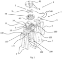
- Fig.1 shows an actuating device 1 according to the invention in a perspective exploded view.
- a base body 2 made of titanium Ti6Al4V (Grade 5) has a total of four base body recesses 100 for the respective accommodation of a drive element 3 in the form of a piezoelectric linear actuator.
- the piezoelectric linear actuators are subjected to a compressive stress in the direction of their longitudinal extension via a prestressing device 120, which comprises a substantially T-shaped prestressing element 121, two compression springs 122 and bearing sections 123.
- the spring element 7 is in the assembled state by means of a Fig.1 not shown fastening element, preferably a screw, to the base body.
- the fastening element cooperates with the fastening part 160 of the base body 2.
- the joint elements 6 protrude through the corresponding openings in the platform base 42 and protrude into corresponding recesses in the respectively facing lever section 10, where they are each connected to the corresponding lever section 10 by a fastening element 140.
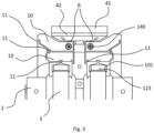
- Fig.2 shows the adjusting device according to the invention according to Fig.1 in assembled state in a side view.
- the Fig.2 The head of the screw 150, which cannot be seen, rests on the spring element 7, while the screw or threaded shaft protrudes through the annular opening 8 of the spring element 7.
- the upper distal end of the respective linear actuator rests against or engages the bearing portion 123 of the pretensioning device 120, wherein the bearing portion 123 is formed in one piece or integrally with the bearing portion 101 of the lever transmission device.
- the first lever section extends over a length of approximately 8 mm, wherein this longitudinal extension direction is arranged substantially perpendicular to the extension direction of the respectively associated linear actuator.
- All solid joints of the lever transmission device have a length of 1 mm and a width of 0.4 mm.
- the fastening element 140 in the form of a screw creates a connection between the second, longer lever section and the respective joint element 6, which is made in one piece with the platform base 42.
- each of the two joint elements 6 shown is formed from a pair of leaf springs 61 and 62, wherein the two leaf springs are arranged substantially perpendicular to each other in order to thereby enable the required degrees of freedom in the corresponding substantially perpendicular movement or tilting directions.
- each of the joint elements is secured by means of a fastening element 140 which is Fig.4 omitted for reasons of clarity, is connected or coupled to the respective associated lever transmission device so that the lever-transmitted deflection of the linear actuator can be transferred to the platform 4.
- a fastening element 140 which is Fig.4 omitted for reasons of clarity, is connected or coupled to the respective associated lever transmission device so that the lever-transmitted deflection of the linear actuator can be transferred to the platform 4.
- the fastening elements 140 are designed as grub screws.
- Fig.6 is a perspective detail of the upper section of the adjusting device according to the Figures 1 to 5 with a section through the platform base 42, whereby the section runs parallel to the platform plane. This allows the arrangement of the spring element 7 in the recess 43 of the platform base 42 to be seen in detail.
- the cross-shaped spring element 7 has an annular central section 8 and four arm sections 9 extending therefrom, wherein adjacent arm sections each enclose an angle of substantially 90 degrees between them.
- the spring element is made of spring sheet or spring steel and has a thickness or material strength of 0.15mm.
- the length of each arm section is 7.5mm, measured from the center of the circular central section, and the width of each arm section is 1.5mm at the narrowest point, i.e. the point with a constant width.
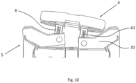
- Fig.7 shows a section perpendicular to the platform plane on an adjusting device according to the Figures 1 to 6
- the arrangement of the spring element 7 between the upper platform part 41 and the lower platform part 42 can again be clearly seen, with the annular central section 8 of the spring element resting on the fastening part 160.
- Fig.8 corresponds in large parts Fig.7 , however, here on the one hand the fastening element 150 is shown in the form of a screw, and on the other hand the fastening elements 170, also designed as screws, which connect the fastening part 160 to the base body 2.
- Fig.9 shows in a perspective view a deflection or positioning situation of the actuating device simulated by calculation according to the Figures 1 to 8 , in which the Fig.9 Leverage device shown at the front left and the Fig.9 not visible diagonally opposite lever transmission device at the rear right. While the linear actuator assigned to the lever transmission device arranged at the front left performs an expansion movement, the diagonally opposite linear actuator performs a contraction movement. Overall, this results in a defined tilting about two tilting axes.
Landscapes
- Physics & Mathematics (AREA)
- General Physics & Mathematics (AREA)
- Optics & Photonics (AREA)
- Mounting And Adjusting Of Optical Elements (AREA)
- Transmission Devices (AREA)
- Details Of Measuring And Other Instruments (AREA)
Applications Claiming Priority (2)
| Application Number | Priority Date | Filing Date | Title |
|---|---|---|---|
| DE102017112517.5A DE102017112517B3 (de) | 2017-06-07 | 2017-06-07 | Stellvorrichtung |
| PCT/DE2018/100536 WO2018224094A1 (de) | 2017-06-07 | 2018-06-05 | Stellvorrichtung |
Publications (2)
| Publication Number | Publication Date |
|---|---|
| EP3635467A1 EP3635467A1 (de) | 2020-04-15 |
| EP3635467B1 true EP3635467B1 (de) | 2024-09-04 |
Family
ID=62814762
Family Applications (1)
| Application Number | Title | Priority Date | Filing Date |
|---|---|---|---|
| EP18736787.5A Active EP3635467B1 (de) | 2017-06-07 | 2018-06-05 | Stellvorrichtung |
Country Status (8)
| Country | Link |
|---|---|
| US (1) | US11275236B2 (he) |
| EP (1) | EP3635467B1 (he) |
| JP (1) | JP7075948B2 (he) |
| KR (1) | KR102371622B1 (he) |
| CN (1) | CN110730918B (he) |
| DE (1) | DE102017112517B3 (he) |
| IL (1) | IL271033B (he) |
| WO (1) | WO2018224094A1 (he) |
Families Citing this family (6)
| Publication number | Priority date | Publication date | Assignee | Title |
|---|---|---|---|---|
| US11448854B2 (en) | 2019-02-21 | 2022-09-20 | Alcon, Inc. | Angle adjustment system |
| KR102413742B1 (ko) * | 2020-06-15 | 2022-06-28 | 고등기술연구원연구조합 | 변위증폭구조를 이용한 초소형 광학용 미러의 팁틸트 메커니즘 |
| CN114942502B (zh) * | 2021-02-09 | 2024-03-26 | 长春长光华大智造测序设备有限公司 | 调节装置及其使用方法 |
| CN113791493B (zh) * | 2021-06-03 | 2022-09-20 | 北京航空航天大学 | 一种基于宏微两级复合作动的快速反射镜 |
| CN114161445A (zh) * | 2021-12-17 | 2022-03-11 | 上海杭和智能科技有限公司 | 机器人打磨通用平台 |
| KR102805130B1 (ko) * | 2024-07-29 | 2025-05-13 | 엘아이지넥스원 주식회사 | 구동 장치 및 이를 포함하는 압전형 조종거울 시스템 |
Family Cites Families (15)
| Publication number | Priority date | Publication date | Assignee | Title |
|---|---|---|---|---|
| JPH05346498A (ja) * | 1992-06-16 | 1993-12-27 | Nkk Corp | ミラ−装置 |
| JP2000338430A (ja) * | 1999-05-28 | 2000-12-08 | Mitsubishi Electric Corp | ミラー傾動機構 |
| FR2822525B1 (fr) | 2001-03-21 | 2003-08-29 | Sagem | Dispositif de fixation et de reglage d'un organe a supporter |
| DE10344178B4 (de) | 2003-09-24 | 2006-08-10 | Carl Zeiss Smt Ag | Halte- und Positioniervorrichtung für ein optisches Element |
| US7738193B2 (en) | 2004-06-29 | 2010-06-15 | Carl Zeiss Smt Ag | Positioning unit and alignment device for an optical element |
| TWI311681B (en) * | 2006-07-04 | 2009-07-01 | Coretronic Corporatio | Reflective mirror module and projection apparatus using the same |
| GB2458146B (en) * | 2008-03-06 | 2013-02-13 | Nanomotion Ltd | Ball-mounted mirror moved by piezoelectric motor |
| JP5196582B2 (ja) | 2009-04-28 | 2013-05-15 | 独立行政法人情報通信研究機構 | 可動鏡機構 |
| DE102009025309B4 (de) * | 2009-06-15 | 2016-12-22 | Toptica Photonics Ag | Kinematischer Halter |
| DE102009037135B4 (de) | 2009-07-31 | 2013-07-04 | Carl Zeiss Laser Optics Gmbh | Haltevorrichtung für ein optisches Element |
| CN102508360A (zh) * | 2011-11-03 | 2012-06-20 | 中国科学院光电技术研究所 | 一种动镜平面微调机构装置 |
| US9052511B1 (en) * | 2012-08-10 | 2015-06-09 | Jeffrey Knirck | Method and apparatus for resonant rotational oscillator |
| US20140061420A1 (en) | 2012-08-20 | 2014-03-06 | National Security Technologies, Llc | Slit Diaphragm Flexure |
| CN106226899B (zh) * | 2016-09-12 | 2019-04-09 | 苏州迈客荣自动化技术有限公司 | 一种偏转镜的微振动平台 |
| DE102018106012B3 (de) * | 2018-03-15 | 2019-03-07 | Jenoptik Optical Systems Gmbh | Justierbare Spiegelbaugruppe mit Blattfederelement |
-
2017
- 2017-06-07 DE DE102017112517.5A patent/DE102017112517B3/de active Active
-
2018
- 2018-06-05 EP EP18736787.5A patent/EP3635467B1/de active Active
- 2018-06-05 JP JP2019567734A patent/JP7075948B2/ja active Active
- 2018-06-05 KR KR1020197038748A patent/KR102371622B1/ko active Active
- 2018-06-05 US US16/620,194 patent/US11275236B2/en active Active
- 2018-06-05 CN CN201880037424.1A patent/CN110730918B/zh active Active
- 2018-06-05 WO PCT/DE2018/100536 patent/WO2018224094A1/de not_active Ceased
-
2019
- 2019-11-28 IL IL271033A patent/IL271033B/he unknown
Also Published As
| Publication number | Publication date |
|---|---|
| JP7075948B2 (ja) | 2022-05-26 |
| US20200088993A1 (en) | 2020-03-19 |
| CN110730918A (zh) | 2020-01-24 |
| US11275236B2 (en) | 2022-03-15 |
| IL271033B (he) | 2022-04-01 |
| DE102017112517B3 (de) | 2018-12-06 |
| KR20200012959A (ko) | 2020-02-05 |
| EP3635467A1 (de) | 2020-04-15 |
| WO2018224094A1 (de) | 2018-12-13 |
| IL271033A (he) | 2020-01-30 |
| KR102371622B1 (ko) | 2022-03-07 |
| CN110730918B (zh) | 2022-02-11 |
| JP2020522758A (ja) | 2020-07-30 |
Similar Documents
| Publication | Publication Date | Title |
|---|---|---|
| EP3635467B1 (de) | Stellvorrichtung | |
| EP1182485B1 (de) | Vorrichtung zum Verstellen der Lage zweier Bauelemente zueinander | |
| DE69924659T2 (de) | Positioniermechanismus | |
| DE19962247A1 (de) | Bewegungsübertragungsvorrichtung | |
| EP2469373B1 (de) | Mehrachsiges Handsteuergerät | |
| DE10026119A1 (de) | Elastische Anordnung | |
| WO2010145803A1 (de) | Kinematischer halter | |
| DE60213570T2 (de) | Vorrichtung zur halterung und justierung eines bauteils | |
| EP3649356B1 (de) | Gelenk | |
| EP1126114B1 (de) | Verstellbares Scharnier | |
| EP3633679A1 (de) | Verstellbarer mechanischer halter zur feinjustage der position eines elements wie einer linse | |
| EP1894258A1 (de) | Positionierer mit festkörpergelenk | |
| DE102004059844B4 (de) | Linearführungsanordnung | |
| DE102018217709B4 (de) | Linearantrieb | |
| EP3072635A2 (de) | Vorrichtung zum abstützen eines zu bearbeitenden werkstücks | |
| EP3856113B1 (de) | Tischsäule für einen operationstisch mit versteifungsmechanismus für eine zylindrische führung | |
| EP4229745B1 (de) | Stellvorrichtung und verfahren zu deren montage | |
| DE3236480A1 (de) | Steuerhebel-zentriervorrichtung | |
| EP4487024B1 (de) | Montageanordnung, positioniervorrichtung mit einer solchen montageanordnung und vorrichtung zur herstellung einer solchen montageanordnung | |
| EP1308818B1 (de) | Bedienungsanordnung zur Betätigung von Steuerorganen durch einen gemeinsamen Bedienhebel | |
| EP3768982B1 (de) | Gelenk | |
| DE102011012388B3 (de) | Justiervorrichtung | |
| WO2012055877A2 (de) | Arbeitsspindel mit festkörpergelenk | |
| EP1805541A1 (de) | Vorrichtung zur justage einer optischen faser oder eines optischen faserbündels | |
| DE10156836B4 (de) | Vorrichtung zur Erzeugung einer rotatorischen Bewegung und Verwendung derselben |
Legal Events
| Date | Code | Title | Description |
|---|---|---|---|
| STAA | Information on the status of an ep patent application or granted ep patent |
Free format text: STATUS: UNKNOWN |
|
| STAA | Information on the status of an ep patent application or granted ep patent |
Free format text: STATUS: THE INTERNATIONAL PUBLICATION HAS BEEN MADE |
|
| PUAI | Public reference made under article 153(3) epc to a published international application that has entered the european phase |
Free format text: ORIGINAL CODE: 0009012 |
|
| STAA | Information on the status of an ep patent application or granted ep patent |
Free format text: STATUS: REQUEST FOR EXAMINATION WAS MADE |
|
| 17P | Request for examination filed |
Effective date: 20191105 |
|
| AK | Designated contracting states |
Kind code of ref document: A1 Designated state(s): AL AT BE BG CH CY CZ DE DK EE ES FI FR GB GR HR HU IE IS IT LI LT LU LV MC MK MT NL NO PL PT RO RS SE SI SK SM TR |
|
| AX | Request for extension of the european patent |
Extension state: BA ME |
|
| DAV | Request for validation of the european patent (deleted) | ||
| DAX | Request for extension of the european patent (deleted) | ||
| STAA | Information on the status of an ep patent application or granted ep patent |
Free format text: STATUS: EXAMINATION IS IN PROGRESS |
|
| 17Q | First examination report despatched |
Effective date: 20220729 |
|
| P01 | Opt-out of the competence of the unified patent court (upc) registered |
Effective date: 20230404 |
|
| GRAP | Despatch of communication of intention to grant a patent |
Free format text: ORIGINAL CODE: EPIDOSNIGR1 |
|
| STAA | Information on the status of an ep patent application or granted ep patent |
Free format text: STATUS: GRANT OF PATENT IS INTENDED |
|
| INTG | Intention to grant announced |
Effective date: 20240507 |
|
| GRAS | Grant fee paid |
Free format text: ORIGINAL CODE: EPIDOSNIGR3 |
|
| RIN1 | Information on inventor provided before grant (corrected) |
Inventor name: TROLL, DANIELA Inventor name: MARTH, HARRY Inventor name: BRAMIGK, ARNE Inventor name: MATHUNI, STEFAN |
|
| GRAA | (expected) grant |
Free format text: ORIGINAL CODE: 0009210 |
|
| STAA | Information on the status of an ep patent application or granted ep patent |
Free format text: STATUS: THE PATENT HAS BEEN GRANTED |
|
| AK | Designated contracting states |
Kind code of ref document: B1 Designated state(s): AL AT BE BG CH CY CZ DE DK EE ES FI FR GB GR HR HU IE IS IT LI LT LU LV MC MK MT NL NO PL PT RO RS SE SI SK SM TR |
|
| REG | Reference to a national code |
Ref country code: GB Ref legal event code: FG4D Free format text: NOT ENGLISH |
|
| REG | Reference to a national code |
Ref country code: CH Ref legal event code: EP |
|
| REG | Reference to a national code |
Ref country code: IE Ref legal event code: FG4D Free format text: LANGUAGE OF EP DOCUMENT: GERMAN Ref country code: NL Ref legal event code: FP |
|
| REG | Reference to a national code |
Ref country code: DE Ref legal event code: R096 Ref document number: 502018015090 Country of ref document: DE |
|
| REG | Reference to a national code |
Ref country code: LT Ref legal event code: MG9D |
|
| PG25 | Lapsed in a contracting state [announced via postgrant information from national office to epo] |
Ref country code: NO Free format text: LAPSE BECAUSE OF FAILURE TO SUBMIT A TRANSLATION OF THE DESCRIPTION OR TO PAY THE FEE WITHIN THE PRESCRIBED TIME-LIMIT Effective date: 20241204 |
|
| PG25 | Lapsed in a contracting state [announced via postgrant information from national office to epo] |
Ref country code: PL Free format text: LAPSE BECAUSE OF FAILURE TO SUBMIT A TRANSLATION OF THE DESCRIPTION OR TO PAY THE FEE WITHIN THE PRESCRIBED TIME-LIMIT Effective date: 20240904 Ref country code: FI Free format text: LAPSE BECAUSE OF FAILURE TO SUBMIT A TRANSLATION OF THE DESCRIPTION OR TO PAY THE FEE WITHIN THE PRESCRIBED TIME-LIMIT Effective date: 20240904 Ref country code: GR Free format text: LAPSE BECAUSE OF FAILURE TO SUBMIT A TRANSLATION OF THE DESCRIPTION OR TO PAY THE FEE WITHIN THE PRESCRIBED TIME-LIMIT Effective date: 20241205 |
|
| PG25 | Lapsed in a contracting state [announced via postgrant information from national office to epo] |
Ref country code: BG Free format text: LAPSE BECAUSE OF FAILURE TO SUBMIT A TRANSLATION OF THE DESCRIPTION OR TO PAY THE FEE WITHIN THE PRESCRIBED TIME-LIMIT Effective date: 20240904 |
|
| PG25 | Lapsed in a contracting state [announced via postgrant information from national office to epo] |
Ref country code: LV Free format text: LAPSE BECAUSE OF FAILURE TO SUBMIT A TRANSLATION OF THE DESCRIPTION OR TO PAY THE FEE WITHIN THE PRESCRIBED TIME-LIMIT Effective date: 20240904 |
|
| PG25 | Lapsed in a contracting state [announced via postgrant information from national office to epo] |
Ref country code: HR Free format text: LAPSE BECAUSE OF FAILURE TO SUBMIT A TRANSLATION OF THE DESCRIPTION OR TO PAY THE FEE WITHIN THE PRESCRIBED TIME-LIMIT Effective date: 20240904 |
|
| PG25 | Lapsed in a contracting state [announced via postgrant information from national office to epo] |
Ref country code: ES Free format text: LAPSE BECAUSE OF FAILURE TO SUBMIT A TRANSLATION OF THE DESCRIPTION OR TO PAY THE FEE WITHIN THE PRESCRIBED TIME-LIMIT Effective date: 20240904 Ref country code: RS Free format text: LAPSE BECAUSE OF FAILURE TO SUBMIT A TRANSLATION OF THE DESCRIPTION OR TO PAY THE FEE WITHIN THE PRESCRIBED TIME-LIMIT Effective date: 20241204 |
|
| PG25 | Lapsed in a contracting state [announced via postgrant information from national office to epo] |
Ref country code: RS Free format text: LAPSE BECAUSE OF FAILURE TO SUBMIT A TRANSLATION OF THE DESCRIPTION OR TO PAY THE FEE WITHIN THE PRESCRIBED TIME-LIMIT Effective date: 20241204 Ref country code: PL Free format text: LAPSE BECAUSE OF FAILURE TO SUBMIT A TRANSLATION OF THE DESCRIPTION OR TO PAY THE FEE WITHIN THE PRESCRIBED TIME-LIMIT Effective date: 20240904 Ref country code: NO Free format text: LAPSE BECAUSE OF FAILURE TO SUBMIT A TRANSLATION OF THE DESCRIPTION OR TO PAY THE FEE WITHIN THE PRESCRIBED TIME-LIMIT Effective date: 20241204 Ref country code: LV Free format text: LAPSE BECAUSE OF FAILURE TO SUBMIT A TRANSLATION OF THE DESCRIPTION OR TO PAY THE FEE WITHIN THE PRESCRIBED TIME-LIMIT Effective date: 20240904 Ref country code: HR Free format text: LAPSE BECAUSE OF FAILURE TO SUBMIT A TRANSLATION OF THE DESCRIPTION OR TO PAY THE FEE WITHIN THE PRESCRIBED TIME-LIMIT Effective date: 20240904 Ref country code: GR Free format text: LAPSE BECAUSE OF FAILURE TO SUBMIT A TRANSLATION OF THE DESCRIPTION OR TO PAY THE FEE WITHIN THE PRESCRIBED TIME-LIMIT Effective date: 20241205 Ref country code: FI Free format text: LAPSE BECAUSE OF FAILURE TO SUBMIT A TRANSLATION OF THE DESCRIPTION OR TO PAY THE FEE WITHIN THE PRESCRIBED TIME-LIMIT Effective date: 20240904 Ref country code: ES Free format text: LAPSE BECAUSE OF FAILURE TO SUBMIT A TRANSLATION OF THE DESCRIPTION OR TO PAY THE FEE WITHIN THE PRESCRIBED TIME-LIMIT Effective date: 20240904 Ref country code: BG Free format text: LAPSE BECAUSE OF FAILURE TO SUBMIT A TRANSLATION OF THE DESCRIPTION OR TO PAY THE FEE WITHIN THE PRESCRIBED TIME-LIMIT Effective date: 20240904 |
|
| PG25 | Lapsed in a contracting state [announced via postgrant information from national office to epo] |
Ref country code: PT Free format text: LAPSE BECAUSE OF FAILURE TO SUBMIT A TRANSLATION OF THE DESCRIPTION OR TO PAY THE FEE WITHIN THE PRESCRIBED TIME-LIMIT Effective date: 20250106 Ref country code: IS Free format text: LAPSE BECAUSE OF FAILURE TO SUBMIT A TRANSLATION OF THE DESCRIPTION OR TO PAY THE FEE WITHIN THE PRESCRIBED TIME-LIMIT Effective date: 20250104 |
|
| PG25 | Lapsed in a contracting state [announced via postgrant information from national office to epo] |
Ref country code: RO Free format text: LAPSE BECAUSE OF FAILURE TO SUBMIT A TRANSLATION OF THE DESCRIPTION OR TO PAY THE FEE WITHIN THE PRESCRIBED TIME-LIMIT Effective date: 20240904 Ref country code: SM Free format text: LAPSE BECAUSE OF FAILURE TO SUBMIT A TRANSLATION OF THE DESCRIPTION OR TO PAY THE FEE WITHIN THE PRESCRIBED TIME-LIMIT Effective date: 20240904 |
|
| PG25 | Lapsed in a contracting state [announced via postgrant information from national office to epo] |
Ref country code: EE Free format text: LAPSE BECAUSE OF FAILURE TO SUBMIT A TRANSLATION OF THE DESCRIPTION OR TO PAY THE FEE WITHIN THE PRESCRIBED TIME-LIMIT Effective date: 20240904 |
|
| PG25 | Lapsed in a contracting state [announced via postgrant information from national office to epo] |
Ref country code: CZ Free format text: LAPSE BECAUSE OF FAILURE TO SUBMIT A TRANSLATION OF THE DESCRIPTION OR TO PAY THE FEE WITHIN THE PRESCRIBED TIME-LIMIT Effective date: 20240904 |
|
| PG25 | Lapsed in a contracting state [announced via postgrant information from national office to epo] |
Ref country code: SK Free format text: LAPSE BECAUSE OF FAILURE TO SUBMIT A TRANSLATION OF THE DESCRIPTION OR TO PAY THE FEE WITHIN THE PRESCRIBED TIME-LIMIT Effective date: 20240904 |
|
| REG | Reference to a national code |
Ref country code: DE Ref legal event code: R097 Ref document number: 502018015090 Country of ref document: DE |
|
| PGFP | Annual fee paid to national office [announced via postgrant information from national office to epo] |
Ref country code: DE Payment date: 20250618 Year of fee payment: 8 |
|
| PG25 | Lapsed in a contracting state [announced via postgrant information from national office to epo] |
Ref country code: DK Free format text: LAPSE BECAUSE OF FAILURE TO SUBMIT A TRANSLATION OF THE DESCRIPTION OR TO PAY THE FEE WITHIN THE PRESCRIBED TIME-LIMIT Effective date: 20240904 |
|
| PGFP | Annual fee paid to national office [announced via postgrant information from national office to epo] |
Ref country code: GB Payment date: 20250620 Year of fee payment: 8 |
|
| PLBE | No opposition filed within time limit |
Free format text: ORIGINAL CODE: 0009261 |
|
| STAA | Information on the status of an ep patent application or granted ep patent |
Free format text: STATUS: NO OPPOSITION FILED WITHIN TIME LIMIT |
|
| PGFP | Annual fee paid to national office [announced via postgrant information from national office to epo] |
Ref country code: NL Payment date: 20250618 Year of fee payment: 8 |
|
| PGFP | Annual fee paid to national office [announced via postgrant information from national office to epo] |
Ref country code: FR Payment date: 20250626 Year of fee payment: 8 |
|
| 26N | No opposition filed |
Effective date: 20250605 |
|
| PG25 | Lapsed in a contracting state [announced via postgrant information from national office to epo] |
Ref country code: SE Free format text: LAPSE BECAUSE OF FAILURE TO SUBMIT A TRANSLATION OF THE DESCRIPTION OR TO PAY THE FEE WITHIN THE PRESCRIBED TIME-LIMIT Effective date: 20240904 |
|
| PGFP | Annual fee paid to national office [announced via postgrant information from national office to epo] |
Ref country code: IT Payment date: 20250630 Year of fee payment: 8 |
|
| PGFP | Annual fee paid to national office [announced via postgrant information from national office to epo] |
Ref country code: CH Payment date: 20250701 Year of fee payment: 8 |
|
| PG25 | Lapsed in a contracting state [announced via postgrant information from national office to epo] |
Ref country code: MC Free format text: LAPSE BECAUSE OF FAILURE TO SUBMIT A TRANSLATION OF THE DESCRIPTION OR TO PAY THE FEE WITHIN THE PRESCRIBED TIME-LIMIT Effective date: 20240904 |
|
| PG25 | Lapsed in a contracting state [announced via postgrant information from national office to epo] |
Ref country code: LU Free format text: LAPSE BECAUSE OF NON-PAYMENT OF DUE FEES Effective date: 20250605 |
|
| REG | Reference to a national code |
Ref country code: BE Ref legal event code: MM Effective date: 20250630 |
|
| PG25 | Lapsed in a contracting state [announced via postgrant information from national office to epo] |
Ref country code: IE Free format text: LAPSE BECAUSE OF NON-PAYMENT OF DUE FEES Effective date: 20250605 |
|
| PG25 | Lapsed in a contracting state [announced via postgrant information from national office to epo] |
Ref country code: BE Free format text: LAPSE BECAUSE OF NON-PAYMENT OF DUE FEES Effective date: 20250630 |