EP3634782B1 - Fahrzeugreifen - Google Patents
Fahrzeugreifen Download PDFInfo
- Publication number
- EP3634782B1 EP3634782B1 EP18714457.1A EP18714457A EP3634782B1 EP 3634782 B1 EP3634782 B1 EP 3634782B1 EP 18714457 A EP18714457 A EP 18714457A EP 3634782 B1 EP3634782 B1 EP 3634782B1
- Authority
- EP
- European Patent Office
- Prior art keywords
- transponder
- tyre
- vehicle tyre
- bead
- tire
- Prior art date
- Legal status (The legal status is an assumption and is not a legal conclusion. Google has not performed a legal analysis and makes no representation as to the accuracy of the status listed.)
- Active
Links
Images

Classifications
-
- B—PERFORMING OPERATIONS; TRANSPORTING
- B60—VEHICLES IN GENERAL
- B60C—VEHICLE TYRES; TYRE INFLATION; TYRE CHANGING; CONNECTING VALVES TO INFLATABLE ELASTIC BODIES IN GENERAL; DEVICES OR ARRANGEMENTS RELATED TO TYRES
- B60C23/00—Devices for measuring, signalling, controlling, or distributing tyre pressure or temperature, specially adapted for mounting on vehicles; Arrangement of tyre inflating devices on vehicles, e.g. of pumps or of tanks; Tyre cooling arrangements
- B60C23/02—Signalling devices actuated by tyre pressure
- B60C23/04—Signalling devices actuated by tyre pressure mounted on the wheel or tyre
- B60C23/0491—Constructional details of means for attaching the control device
- B60C23/0493—Constructional details of means for attaching the control device for attachment on the tyre
-
- G—PHYSICS
- G06—COMPUTING OR CALCULATING; COUNTING
- G06K—GRAPHICAL DATA READING; PRESENTATION OF DATA; RECORD CARRIERS; HANDLING RECORD CARRIERS
- G06K19/00—Record carriers for use with machines and with at least a part designed to carry digital markings
- G06K19/06—Record carriers for use with machines and with at least a part designed to carry digital markings characterised by the kind of the digital marking, e.g. shape, nature, code
- G06K19/067—Record carriers with conductive marks, printed circuits or semiconductor circuit elements, e.g. credit or identity cards also with resonating or responding marks without active components
- G06K19/07—Record carriers with conductive marks, printed circuits or semiconductor circuit elements, e.g. credit or identity cards also with resonating or responding marks without active components with integrated circuit chips
- G06K19/077—Constructional details, e.g. mounting of circuits in the carrier
- G06K19/07749—Constructional details, e.g. mounting of circuits in the carrier the record carrier being capable of non-contact communication, e.g. constructional details of the antenna of a non-contact smart card
- G06K19/07758—Constructional details, e.g. mounting of circuits in the carrier the record carrier being capable of non-contact communication, e.g. constructional details of the antenna of a non-contact smart card arrangements for adhering the record carrier to further objects or living beings, functioning as an identification tag
- G06K19/07764—Constructional details, e.g. mounting of circuits in the carrier the record carrier being capable of non-contact communication, e.g. constructional details of the antenna of a non-contact smart card arrangements for adhering the record carrier to further objects or living beings, functioning as an identification tag the adhering arrangement making the record carrier attachable to a tyre
-
- H—ELECTRICITY
- H01—ELECTRIC ELEMENTS
- H01Q—ANTENNAS, i.e. RADIO AERIALS
- H01Q1/00—Details of, or arrangements associated with, antennas
- H01Q1/12—Supports; Mounting means
- H01Q1/22—Supports; Mounting means by structural association with other equipment or articles
- H01Q1/2208—Supports; Mounting means by structural association with other equipment or articles associated with components used in interrogation type services, i.e. in systems for information exchange between an interrogator/reader and a tag/transponder, e.g. in Radio Frequency Identification [RFID] systems
- H01Q1/2241—Supports; Mounting means by structural association with other equipment or articles associated with components used in interrogation type services, i.e. in systems for information exchange between an interrogator/reader and a tag/transponder, e.g. in Radio Frequency Identification [RFID] systems used in or for vehicle tyres
-
- B—PERFORMING OPERATIONS; TRANSPORTING
- B60—VEHICLES IN GENERAL
- B60C—VEHICLE TYRES; TYRE INFLATION; TYRE CHANGING; CONNECTING VALVES TO INFLATABLE ELASTIC BODIES IN GENERAL; DEVICES OR ARRANGEMENTS RELATED TO TYRES
- B60C19/00—Tyre parts or constructions not otherwise provided for
- B60C2019/004—Tyre sensors other than for detecting tyre pressure
-
- H—ELECTRICITY
- H01—ELECTRIC ELEMENTS
- H01Q—ANTENNAS, i.e. RADIO AERIALS
- H01Q9/00—Electrically-short antennas having dimensions not more than twice the operating wavelength and consisting of conductive active radiating elements
- H01Q9/04—Resonant antennas
- H01Q9/16—Resonant antennas with feed intermediate between the extremities of the antenna, e.g. centre-fed dipole
- H01Q9/26—Resonant antennas with feed intermediate between the extremities of the antenna, e.g. centre-fed dipole with folded element or elements, the folded parts being spaced apart a small fraction of operating wavelength
Definitions
- the invention relates to a vehicle tire.
- Transponders can be used in the tire for various tasks. This includes, in particular, a tire identification with which an automobile manufacturer, inter alia. can quickly and automatically determine from which tire plant a certain tire was delivered or whether the delivered tire corresponds to the desired dimension or specification.
- Modern transponders consist of an electronic component or chip, in which sensor elements can be arranged, as well as an antenna connected to this electronic component.
- the transponder must be integrated into the manufacturing process for vehicle tires. If the material is used up, the transponders can be destroyed.
- the invention is based on the object of providing a vehicle tire with a transponder in which the transponder can be easily integrated in the vehicle tire.
- the new arrangement of the transponder in the tire bead permanently protects the transponder from high material stresses.
- the transponder is placed in an area of the tire bead that is exposed to very little material stress when the vehicle tire rolls off.
- the tire core with the core wires has a high rigidity and can only deform very little.
- the transponder is protected from material stress by the apex.
- Another advantage is that the transponder is arranged in a special height area on the outside of the apex. This enables a simple radio link with a high signal quality to be implemented to the transponder.
- the transponder is arranged in the tire bead between the second carcass ply and a flap.
- the transponder is particularly well protected from external material stresses by the bulge tape.
- the transponder is arranged in the tire bead between a bead band and a bead reinforcement.
- An embodiment according to the invention shows Figure 2 .
- the transponder is particularly well protected from external material stresses due to the arrangement behind the bead reinforcement.
- the height dimension in the radial direction of the vehicle tire between the transponder and the upper tip of the apex is at least 5 mm.
- the transponder is arranged in an area of the tire bead in which the mechanical stress on the vehicle tire when the vehicle is being driven is relatively low.
- the core and the apex is covered with a rubber layer.
- the rubber layer is a rubberized textile or steel cord layer and is referred to as a "flipper component" and contributes to the stability of the tire bead.
- the rubber layer improves the protection of the transponder against mechanical loads.
- the transponder is aligned with its two antenna parts in the circumferential direction to the tire core. This means that the transponder is optimally aligned in the tire bead in order to ensure optimal transmission and reception performance.
- the transponder is a film-shaped RFID transponder, wherein the transponder chip and the antennas are embedded in a carrier film.
- Foil-shaped RFID transponders have a very low material thickness. The high flexibility of these transponders makes them particularly suitable for use between tire components.
- the carrier film has a material thickness of less than 1 mm. With this material thickness, the film-shaped RFID transponder has a particularly high degree of flexibility.
- the flexible plastic material can be easily connected to the rubber material of the surrounding tire components.
- the carrier film consists of a flexible plastic.
- the film-shaped transponder has an additional material coating.
- the material coating improves the connection to the adjacent tire components.
- the material coating comprises a rubber material.
- the material coating comprises an adhesion promoter system, whereby the bonding to the surrounding tire components is improved with the adhesion promoter system.
- the adhesion promoter system could, for example, be a chemical solution that is applied to the film-shaped RFID transponder in order to improve the connection to the adjacent tire components. It could also be a chemical solution that is only activated when the tire is vulcanized.
- the transponder has a width between 3 and 20 mm and a length between 30 and 100 mm. Given these dimensions of the transponder, it can be arranged in a simple manner between the tire components.
- the transponder is a transponder with two spiral antennas. This type of transponder has a long service life and is therefore suitable for use between tire components.
- the transponder with the two spiral antennas is embedded between two layers of rubber material. This significantly improves the durability of the transponder.
- the transponder is applied during the pre-assembly of the tire component group from the tire core and apex.
- the transponder can simply be placed on the outside of the apex when this tire component group is pre-assembled.
- the transponder in the vehicle tire is used in connection with a device for indirect monitoring of tire pressure, wherein the device for the indirect monitoring receives information on a tire change from the transponder.
- the transponder has an individual tire identification.
- the vehicle has, for example, a reader in the wheel arch for reading out the tire identification.
- the device for indirect monitoring recognizes that a new tire has been fitted and then automatically performs a system reset.
- the device for indirect monitoring of tire pressure is also referred to as a deflation detection system (DDS).
- DDS deflation detection system
- the driver With conventional devices for indirect monitoring of the tire pressure, the driver always has to perform the system reset manually after a tire change.
- further information is stored on the transponder, by means of which the device for indirect monitoring can work with a higher degree of accuracy. This information includes details of the manufacturer, the tire dimensions, the exact tire circumference and the tire construction.
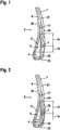
- the Figure 1 schematically shows the cross section of a tire bead 8.
- the transponder 1 is arranged in the tire bead 8 between a second carcass ply 21 and the outside 24 of the tire. It is especially a tire bead construction for commercial vehicle tires.
- the transponder 1 is arranged between the second carcass ply 21 and the flap 22, which is also referred to as chafer.
- the first carcass ply 6 forms a ply envelope 17 in the tire bead 8, which is guided around the apex 5 and the tire core 4.
- the tire core 4 comprises a large number of wire cores and therefore has a very high material rigidity.
- the transponder is arranged in a particularly calmed material zone of the vehicle tire that is only exposed to low material loads.
- An additional rubber layer 9, which is also referred to as a "flipper component" can optionally be arranged around the apex 5 and the apex core 4.
- the rubber layer is a rubberized textile or steel cord layer.
- the height 18 between the transponder 1 and the underside of the apex 5 is at least 3 mm, preferably at least 5 mm or at least 7 mm. By the higher Positioning the transponder 1 enables the signal transmission to the receiving device to be implemented better.
- the height 19 between the transponder 1 and the tip of the apex 5 is at least 5 mm, preferably at least 7 mm or at least 9 mm. The data of the transponder can thus be read out very easily with an external reader.
- the Figure 2 shows a further embodiment.
- the transponder 1 is arranged in the tire bead 8 between a second carcass ply 21 and the outside 24 of the tire. It is especially a tire bead construction for commercial vehicle tires.
- the transponder 1 is arranged between the flap 22 and a bead reinforcement 25, which can have steel cord strength supports.
- the other tire components correspond to those in Fig. 1 illustrated tire components.
- the Figure 3 shows a plan view of the film-shaped RFID transponder.
- the transponder essentially comprises the transponder chip 6 and the two connected antennas 2 and 3 in the middle. All components are embedded in a carrier film 11, which consists of plastic and has a high flexibility.
- the material thickness of the foil-shaped RFID transponder is less than 1 mm.
- the length 16 of the transponder is between 30 and 100 mm.
- the width 15 of the transponder is between 3 and 20 mm.
- the Figure 4 shows an embodiment for a transponder with two spiral antennas 13 and 14, which are connected to the transponder chip 6.
- the antennas 13 and 14 are made of a metal and have a high fatigue strength.
- the transponder 13 can optionally be embedded between two strips of rubber material before it is placed between the tire core and the apex during pre-assembly.
Landscapes
- Engineering & Computer Science (AREA)
- Mechanical Engineering (AREA)
- Computer Hardware Design (AREA)
- Microelectronics & Electronic Packaging (AREA)
- Physics & Mathematics (AREA)
- General Physics & Mathematics (AREA)
- Theoretical Computer Science (AREA)
- Tires In General (AREA)
Description
- Die Erfindung betrifft einen Fahrzeugreifen.
- Transponder können im Reifen für verschiedene Aufgaben eingesetzt werden. Hierzu zählt insbesondere eine Reifenidentifikation mit der ein Automobilhersteller u. a. schnell sowie automatisiert feststellen kann, aus welchem Reifenwerk ein bestimmter Reifen geliefert wurde oder ob der gelieferte Reifen der gewünschten Dimension oder Spezifikation entspricht. Moderne Transponder bestehen aus einem Elektronikbauteil bzw. -Chip, in dem Sensorelemente angeordnet sein können sowie aus einer an dieses Elektronikbauteil angeschlossenen Antenne.
- Der Transponder muss in den Herstellungsprozess für Fahrzeugreifen integriert werden. Bei einer bestimmten Materialanspruchung können die Transponder zerstört werden.
- Aus dem Stand der Technik sind unterschiedliche Konzepte bekannt, den Transponder im oder am Reifen anzuordnen. Alle herkömmlichen Konzepte besitzen unterschiedliche Nachteile.
- Die
US 2010/122757 A 1,EP 1 978 345 A2 ,US 2008/303674 A1 ,DE 10209580 A1 ,EP 1310 386A2 ,JP 2016 049920 A WO 2015/088890 A1 offenbaren unterschiedliche Fahrzeugreifen mit Transpondern. - Der Erfindung liegt die Aufgabe zugrunde, einen Fahrzeugreifen mit einem Transponder bereitzustellen, bei dem der Transponder auf einfache Weise im Fahrzeugreifen integriert werden kann.
- Gelöst wird die Aufgabe gemäß Anspruch 1.
- Ein Vorteil der Erfindung ist insbesondere darin zu sehen, dass durch die neuartige Anordnung des Transponders im Reifenwulst der Transponder dauerhaft vor hohen Materialbeanspruchungen geschützt ist. Der Transponder ist in einem Bereich des Reifenwulstes platziert, der beim Abrollen des Fahrzeugreifens nur sehr geringen Materialbelastungen ausgesetzt ist. Der Reifenkern mit den Kerndrähten besitzt eine hohe Steifigkeit und kann sich nur sehr wenig verformen. Außerdem wird der Transponder durch den Kernreiter zusätzlich vor Materialbeanspruchungen geschützt.
Ein weiterer Vorteil besteht darin, dass der Transponder in einem besonderen Höhenbereich der Außenseite des Kernreiters angeordnet ist. Dadurch läßt sich eine einfache Funkverbindung mit einer hohen Signalqualität zum Transponder realisieren. - In dem Beispiel gemäß
Figur 1 ist der Transponder im Reifenwulst zwischen der zweiten Karkasslage und einem Wulstband angeordnet . Der Transponder ist durch das Wulstband besonders gut vor äußeren Materialbeanspruchungen geschützt. - Erfindungsgemäβ ist vorgesehen, dass der Transponder im Reifenwulst zwischen einem Wulstband und einem Wulstverstärker angeordnet ist.
Ein erfindungsgemäßes Ausführungsbeispiel zeigt dieFigur 2 . Der Transponder ist durch die Anordnung hinter dem Wulstverstärker besonders gut vor äußeren Materialbeanspruchungen geschützt. - In einer weiteren vorteilhaften Weiterbildung der Erfindung ist vorgesehen, dass die Höhenabmessung in radialer Richtung des Fahrzeugreifens zwischen dem Transponder und der oberen Spitze des Kernreiters mindestens 5 mm beträgt.
Dadurch ist der Transponder in einem Bereich des Reifenwulstes angeordnet in dem die mechanische Beanspruchung im Fahrbetrieb des Fahrzeugreifens relativ gering ist. - In einer weiteren vorteilhaften Weiterbildung der Erfindung ist vorgesehen, dass der Kern und der Kernreiter mit einer Gummilage überdeckt ist.
- Die Gummilage ist eine gummierte Textil- oder Stahlcordlage und wird als "Flipper-Bauteil" bezeichnet und trägt zur Stabilität des Reifenwulstes bei.
Die Gummilage verbessert den Schutz des Transponders vor mechanischen Belastungen. - In einer vorteilhaften Weiterbildung der Erfindung ist vorgesehen, dass der Transponder mit seinen beiden Antennenteilen in Umfangsrichtung zum Reifenkern ausgerichtet ist. Dadurch besitzt der Transponder eine optimale Ausrichtung im Reifenwulst, um eine optimale Sende- und Empfangsleistung zu gewährleisten.
- In einer weiteren vorteilhaften Weiterbildung der Erfindung ist vorgesehen, dass der Transponder ein folienförmiger RFID-Transponder ist,
wobei der Transponder-Chip und die Antennen in einer Trägerfolie eingebettet sind. Folienförmige RFID-Transponder besitzen eine sehr geringe Materialdicke. Durch die hohe Biegsamkeit dieser Transponder sind sie besonders für den Einsatz zwischen Reifenbauteilen geeignet. - In einer weiteren vorteilhaften Weiterbildung der Erfindung ist vorgesehen, dass die Trägerfolie eine Materialdicke von kleiner als 1mm besitzt.
Bei dieser Materialdicke besitzt der folienförmige RFID-Transponder eine besonders hohe Flexibilität. Das flexible Kunststoffmaterial lässt sich gut mit dem Gummimaterial der umgebenden Reifenbauteile verbinden. - In einer weiteren vorteilhaften Weiterbildung der Erfindung ist vorgesehen, dass die Trägerfolie aus einem flexiblen Kunststoff besteht.
In einer weiteren vorteilhaften Weiterbildung der Erfindung ist vorgesehen, dass der folienförmige Transponder eine zusätzliche Materialbeschichtung aufweist. - Durch diese Materialbeschichtung lässt sich die Verbindung zu den angrenzenden Reifenbauteilen verbessern.
In einer weiteren vorteilhaften Weiterbildung der Erfindung ist vorgesehen, dass die Materialbeschichtung ein Gummimaterial umfasst. - In einer weiteren vorteilhaften Weiterbildung der Erfindung ist vorgesehen, dass die Materialbeschichtung ein Haftvermittlersystem umfasst,
wobei mit dem Haftvermittlersystem die Anbindung an die umgebenden Reifenbauteile verbessert wird.
Das Haftvermittlersystem könnte beispielsweise eine chemische Lösung sein, die auf den folienförmigen RFID-Transponder aufgetragen wird, um die Anbindung zu den angrenzenden Reifenbauteilen zu verbessern. Es könnte sich dabei auch um eine chemische Lösung handeln, die erst bei der Reifenvulkanisation aktiviert wird. - In einer weiteren vorteilhaften Weiterbildung der Erfindung ist vorgesehen, dass der Transponder eine Breite zwischen 3 und 20 mm sowie eine Länge zwischen 30 und 100 mm aufweist.
Bei diesen Abmessungen des Transponders lässt sich dieser auf einfache Weise zwischen den Reifenbauteilen anordnen. - In einer weiteren vorteilhaften Weiterbildung der Erfindung ist vorgesehen, dass der Transponder ein Transponder mit zwei spiralförmigen Antennen ist.
Diese Art von Transpondern weisen eine hohe Dauerhaltbarkeit auf und eigenen sich daher für den Einsatz zwischen Reifenbauteilen. - In einer weiteren vorteilhaften Weiterbildung der Erfindung ist vorgesehen, dass der Transponder mit den zwei spiralförmigen Antennen zwischen zwei Materialagen aus Gummimaterial eingebettet ist.
Dadurch wird die Dauerhaltbarkeit des Transponders wesentlich verbessert. - In einer weiteren vorteilhaften Weiterbildung der Erfindung ist vorgesehen, dass der Transponder bei der Vorkonfektionierung der Reifenbauteilgruppe aus Reifenkern und Kernreiter aufgebracht wird.
Der Transponder lässt sich bei der Vorkonfektionierung dieser Reifenbauteilgruppe einfach auf der Außenseite des Kernreiters platzieren. - In einer weiteren vorteilhaften Weiterbildung der Erfindung ist vorgesehen, dass der Transponder im Fahrzeugreifen in Verbindung mit einer Vorrichtung zur indirekten Überwachung eines Reifendruckes genutzt wird,
wobei die Vorrichtung für die indirekte Überwachung eine Information zu einem Reifenwechsel von dem Transponder erhält. - Der Transponder besitzt eine individuelle Reifenidentifikation. Das Fahrzeug besitzt z.B. im Radhaus eine Lesegerät zum Auslesen der Reifenidentifikation. Bei einem Reifenwechsel erkennt die Vorrichtung für die indirekte Überwachung, dass ein neuer Reifen montiert worden ist und führt anschließend automatisch ein Systemreset durch. Die Vorrichtung für die indirekte Überwachung des Reifendruckes werden ebenfalls als Deflation Detection System (DDS) bezeichnet.
Bei herkömmlichen Vorrichtung für eine indirekte Überwachung des Reifendruckes muss der Fahrer immer nach einem Reifenwechsel den Systemreset manuell durchführen. Außerdem sind auf dem Transponder weitere Informationen gespeichert, durch die die Vorrichtung für die indirekte Überwachung mit einer höheren Genauigkeit arbeiten kann. Diese Informationen umfassen Angaben zum Hersteller, zur Reifendimension, zum exakten Reifenumfang und zur Reifenkonstruktion. - Anhand mehrerer Ausführungsbeispiele soll die Erfindung näher erläutert werden. Es zeigen:
-
Fig. 1 : einen Reifenwulst -
Fig. 2 : einen Reifenwulst -
Fig. 3 : eine Aufsicht auf den folienförmige RFID-Transponder -
Fig. 4 : eine Aufsicht auf den Transponder mit spiralförmigen Antennen - Die
Figur 1 zeigt schematisch den Querschnitt eines Reifenwulstes 8.
Der Transponder 1 ist im Reifenwulst 8 zwischen einer zweiten Karkasslage 21 und der Reifenaußenseite 24 angeordnet. Es handelt sich insb. um eine Reifenwulstkonstruktion für NFZ-Reifen. - Bei dieser nicht erfindungsgemäßen Ausführung ist der Transponder 1 zwischen der zweiten Karkasslage 21 und dem Wulstband 22 angeordnet, welches ebenfalls als Chafer bezeichnet wird. Die erste Karkasslage 6 bildet im Reifenwulst 8 einen Lagenumschlag 17, der um den Kernreiter 5 und den Reifenkern 4 herumgeführt ist. Der Reifenkern 4 umfasst eine Vielzahl von Drahtkernen und hat daher eine sehr hohe Materialsteifigkeit. Durch diese Materialsteifigkeit des Reifenkerns ist der Transponder in einer besonders beruhigten Materialzone des Fahrzeugreifens angeordnet, die nur geringen Materialbelastungen ausgesetzt ist.
Um den Kernreiter 5 und den Reifernkern 4 kann optional eine zusätzliche Gummilage 9 angeordnet sein, die ebenfalls als "Flipper-Bauteil" bezeichnet wird.
Bei der Gummilage handelt es sich um eine gummierte Textil- oder Stahlcordlage.
Die Höhe 18 zwischen Transponder 1 und Unterseite des Kernreiters 5 beträgt mindestens 3 mm, vorzugsweise mindestens 5 mm oder mindestens 7 mm. Durch die höhere
Positionierung des Transponders 1 läßt sich die Signalübertragung zum Empfangsgerät besser realisieren.
Außerdem beträgt die Höhe 19 zwischen Transponder 1 und der Spitze des Kernreiters 5 mindestens 5 mm, vorzugsweise mindestens 7 mm oder mindestens 9 mm.
Die Daten des Transponders lassen sich dadurch sehr gut mit einem externen Lesegerät auslesen. - Die
Figur 2 zeigt ein weiteres Ausführungsbeispiel.
Der Transponder 1 ist im Reifenwulst 8 zwischen einer zweiten Karkasslage 21 und der Reifenaußenseite 24 angeordnet. Es handelt sich insb. um eine Reifenwulstkonstruktion für NFZ-Reifen.
Bei dieser erfindungsgemäßen Ausführung ist der Transponder 1 zwischen dem Wulstband 22 und einem Wulstverstärker 25 angeordnet, der Stahlcordfestigkeitsträger aufweisen kann. Die anderen Reifenbauteile entsprechen den in derFig. 1 dargestellten Reifenbauteilen. - Die
Figur 3 zeigt eine Aufsicht auf den folienförmigen RFID-Transponder. Der Transponder umfasst im Wesentlichen in der Mitte den Transponder-Chip 6 und die beiden angebundenen Antennen 2 und 3. Alle Bauteile sind in eine Trägerfolie 11 eingebettet, die aus Kunststoff besteht und eine hohe Flexibilität besitzt. Die Materialdicke des folienförmigen RFID-Transponders beträgt weniger als 1 mm. Die Länge 16 des Transponders beträgt zwischen 30 und 100 mm. Die Breite 15 des Transponders beträgt zwischen 3 und 20 mm. - Die
Figur 4 zeigt ein Ausführungsbeispiel für einen Transponder mit zwei spiralförmigen Antennen 13 und 14, die an den Transponder-Chip 6 angebunden sind.
Die Antennen 13 und 14 bestehen aus einem Metall und besitzen eine hohe Dauerfestigkeit.
Der Transponder 13 kann optional zwischen zwei Materialstreifen aus Gummi eingebettet sein, bevor er bei der Vorkonfektionierung zwischen dem Reifenkern und dem Kernreiter platziert wird. -
- 1
- Transponder
- 2
- linke Antenne
- 3
- rechte Antenne
- 4
- Reifenkern
- 5
- Kernreiter bzw. Apex
- 6
- Erste Karkasslage
- 7
- Seitenwand
- 8
- Reifenwulst
- 9
- Gummibauteil
- 10
- Folienförmiger RFID-Transponder
- 11
- Trägerfolie
- 12
- Länge des Folienförmigen RFID-Transponders
- 13
- Transponder mit zwei spiralförmigen Antennen
- 14
- Linke spiralförmige Antenne
- 15
- Rechte spiralförmige Antenne
- 16
- Länge des Transponders
- 17
- Äußere Lagenumschlag der Karkasslage
- 18
- Höhe zwischen Transponder und Unterseite des Kernreiters
- 19
- Höhe zwischen Transponder und Spitze des Kernreiters
- 20
- Reifeninnenseele
- 21
- Zweite Karkasslage mit Stahlcordfestigkeitsträgern
- 22
- Wulstband bzw. Chafer
- 23
- Äußeres Gummibauteil bzw. Rimstrip
- 24
- Reifenaußenseite
- 25
- Wulstverstärker
Claims (13)
- Fahrzeugreifen mit einem Laufstreifen, einem Reifengürtel, einer Reifenkarkasse mit mindestens einer Karkasslage (6), Seitenwänden (7) und einem Reifenwulst (8) mit einem Reifenkern (4) sowie einem Kernreiter (5),
wobei der Reifenkern (4) im Querschnitt eine Vielzahl von Festigkeitsträgern umfasst und der Kernreiter (5) auf seiner Unterseite an der Oberseite des Reifenkerns (4) angebunden ist,
wobei der Fahrzeugreifen ferner einen Transponder (1) mit einen Transponderchip (6) und eine an den Transponderchip (6) angebundende Antenne (2, 3, 14, 15) aufweist,
wobei die Höhenabmessung (18) in radialer Richtung des Fahrzeugreifens zwischen dem Transponder (1) und der Unterseite des Kernreiters (5) mindestens 3 mm beträgt.
dadurch gekennzeichnet, dass
der Transponder (1) im Reifenwulst (8) zwischen einer zweiten Karkasslage (21) und der Reifenaußenseite (24) angeordnet ist und wobei der Transponder (1) im Reifenwulst außerdem zwischen einem Wulstband (22) und einem Wulstverstärker (25) angeordnet ist. - Fahrzeugreifen nach Anspruch 1,
dadurch gekennzeichnet, dass
die Höhenabmessung (19) in radialer Richtung des Fahrzeugreifens zwischen dem Transponder (1) und der oberen Spitze des Kernreiters (5) mindestens 5 mm beträgt. - Fahrzeugreifen nach einem der vorhergehenden Ansprüche,
dadurch gekennzeichnet, dass
der Kern (4) und der Kernreiter (5) mit einer Gummilage (9) überdeckt ist. - Fahrzeugreifen nach einem der vorhergehenden Ansprüche,
dadurch gekennzeichnet, dass
der Transponder (1) mit seiner Antenne (2, 3, 14, 15) in Umfangsrichtung zum Reifenkern (4) ausgerichtet ist. - Fahrzeugreifen nach einem der vorhergehenden Ansprüche,
dadurch gekennzeichnet, dass
der Transponder (1) ein folienförmiger RFID-Transponder (10) ist,
wobei der Transponder-Chip (6) und die Antenne (2, 3) in einer Trägerfolie (16) eingebettet sind. - Fahrzeugreifen nach Anspruch 5,
dadurch gekennzeichnet, dass
die Trägerfolie (16) eine Materialdicke von kleiner als 1mm besitzt. - Fahrzeugreifen nach Anspruch 5,
dadurch gekennzeichnet, dass
die Trägerfolie (16) aus einem flexiblen Kunststoff besteht. - Fahrzeugreifen nach Anspruch 5,
dadurch gekennzeichnet, dass
der folienförmige Transponder (10) eine zusätzliche Materialbeschichtung aufweist. - Fahrzeugreifen nach Anspruch 8,
dadurch gekennzeichnet, dass
die Materialbeschichtung ein Gummimaterial umfasst. - Fahrzeugreifen nach Anspruch 8,
dadurch gekennzeichnet, dass
die Materialbeschichtung ein Haftvermittlersystem umfasst,
wobei mit dem Haftvermittlersystem die Anbindung an die umgebenden Reifenbauteile verbessert wird. - Fahrzeugreifen nach einem der vorhergehenden Ansprüche,
dadurch gekennzeichnet, dass
der Transponder (1, 10, 13) eine Breite zwischen 3 und 20 mm sowie eine Länge (16) zwischen 30 und 100 mm aufweist. - Fahrzeugreifen nach einem der vorhergehenden Ansprüche,
dadurch gekennzeichnet, dass
der Transponder (1) ein Transponder (13) mit zwei spiralförmigen Antennen ist. - Fahrzeugreifen nach Anspruch 12,
dadurch gekennzeichnet, dass
der Transponder (13) mit den zwei spiralförmigen Antennen zwischen zwei Materialagen aus Gummimaterial eingebettet ist.
Applications Claiming Priority (2)
| Application Number | Priority Date | Filing Date | Title |
|---|---|---|---|
| DE102017209541.5A DE102017209541A1 (de) | 2017-06-07 | 2017-06-07 | Fahrzeugreifen |
| PCT/EP2018/056530 WO2018224194A1 (de) | 2017-06-07 | 2018-03-15 | Fahrzeugreifen |
Publications (2)
| Publication Number | Publication Date |
|---|---|
| EP3634782A1 EP3634782A1 (de) | 2020-04-15 |
| EP3634782B1 true EP3634782B1 (de) | 2021-06-23 |
Family
ID=61832477
Family Applications (1)
| Application Number | Title | Priority Date | Filing Date |
|---|---|---|---|
| EP18714457.1A Active EP3634782B1 (de) | 2017-06-07 | 2018-03-15 | Fahrzeugreifen |
Country Status (3)
| Country | Link |
|---|---|
| EP (1) | EP3634782B1 (de) |
| DE (1) | DE102017209541A1 (de) |
| WO (1) | WO2018224194A1 (de) |
Families Citing this family (9)
| Publication number | Priority date | Publication date | Assignee | Title |
|---|---|---|---|---|
| JP7227847B2 (ja) * | 2019-05-17 | 2023-02-22 | Toyo Tire株式会社 | タイヤ |
| JP7345290B2 (ja) * | 2019-06-19 | 2023-09-15 | Toyo Tire株式会社 | タイヤ |
| FR3101171B1 (fr) | 2019-09-25 | 2022-08-05 | Michelin & Cie | pneumatique EQUIPE d’un Transpondeur radiofréquence |
| FR3101170B1 (fr) * | 2019-09-25 | 2022-08-05 | Michelin & Cie | pneumatique EQUIPE d’un Transpondeur radiofréquence |
| FR3101019B1 (fr) * | 2019-09-25 | 2022-12-16 | Michelin & Cie | pneumatique EQUIPE d’un Transpondeur radiofréquence |
| DE112021000321B4 (de) * | 2020-02-17 | 2023-11-09 | The Yokohama Rubber Co., Ltd. | Luftreifen |
| JP7599903B2 (ja) * | 2020-10-27 | 2024-12-16 | Toyo Tire株式会社 | タイヤ |
| JP7545046B2 (ja) * | 2020-10-29 | 2024-09-04 | 横浜ゴム株式会社 | 空気入りタイヤ |
| DE102024207563A1 (de) * | 2024-08-08 | 2026-02-12 | Continental Reifen Deutschland Gmbh | Fahrzeugreifen |
Family Cites Families (11)
| Publication number | Priority date | Publication date | Assignee | Title |
|---|---|---|---|---|
| DE10154494A1 (de) * | 2001-11-08 | 2003-05-22 | Continental Ag | Sende- und/oder Empfangseinrichtung zum Einbau in elastische Strukturen sowie Antennen hierfür |
| DE10209580B4 (de) * | 2002-03-05 | 2014-01-30 | Goodyear Dunlop Tires Germany Gmbh | Fahrzeugreifen mit integriertem Transponder |
| JPWO2005095127A1 (ja) * | 2004-03-31 | 2008-02-21 | 株式会社ブリヂストン | 無線icタグ取付ホルダー、及び無線icタグ付きタイヤ |
| FR2914585B1 (fr) * | 2007-04-03 | 2009-07-03 | Michelin Soc Tech | Pneumatique comprenant un organe electronique et procede de fabrication d'un tel pneumatique |
| EP1978345B1 (de) * | 2007-04-06 | 2014-05-07 | Sumitomo Rubber Industries, Ltd. | Verfahren zur Schätzung der Größe einer Kraft, die auf einen rollenden Reifen einwirkt |
| FR2936185B1 (fr) * | 2008-09-25 | 2011-09-23 | Michelin Soc Tech | Pneumatique muni d'un organe a antenne deportee |
| US20100122757A1 (en) * | 2008-11-18 | 2010-05-20 | Robert Edward Lionetti | Tire and electronic device assembly |
| JP2013126838A (ja) * | 2011-12-19 | 2013-06-27 | Toppan Forms Co Ltd | タイヤ |
| JP6276859B2 (ja) * | 2013-12-13 | 2018-02-07 | ブリヂストン アメリカズ タイヤ オペレーションズ、 エルエルシー | 下部サイドウォール内に電子デバイスを有するタイヤ |
| JP6423644B2 (ja) * | 2014-08-08 | 2018-11-14 | 株式会社ブリヂストン | タイヤ |
| JP6423653B2 (ja) * | 2014-09-01 | 2018-11-14 | 株式会社ブリヂストン | タイヤ |
-
2017
- 2017-06-07 DE DE102017209541.5A patent/DE102017209541A1/de not_active Withdrawn
-
2018
- 2018-03-15 WO PCT/EP2018/056530 patent/WO2018224194A1/de not_active Ceased
- 2018-03-15 EP EP18714457.1A patent/EP3634782B1/de active Active
Non-Patent Citations (1)
| Title |
|---|
| None * |
Also Published As
| Publication number | Publication date |
|---|---|
| WO2018224194A1 (de) | 2018-12-13 |
| DE102017209541A1 (de) | 2018-12-13 |
| EP3634782A1 (de) | 2020-04-15 |
Similar Documents
| Publication | Publication Date | Title |
|---|---|---|
| EP3634782B1 (de) | Fahrzeugreifen | |
| EP3634784B1 (de) | Fahrzeugreifen | |
| EP3634783B1 (de) | Fahrzeugreifen | |
| DE102020003646B4 (de) | Reifen | |
| EP3887176B1 (de) | Fahrzeugreifen | |
| EP3413243B1 (de) | Fahrzeugreifen | |
| DE102007030238B4 (de) | Fahrzeugluftreifen mit einem Elektronikmodul | |
| EP3740387B1 (de) | Verfahren zur herstellung eines transponders für einen fahrzeugreifen | |
| DE602004012627T2 (de) | Luftreifen mit antenne für fahrzeugräder und herstellungsverfahren dafür | |
| DE102017209551A1 (de) | Fahrzeugreifen | |
| DE102017209539A1 (de) | Fahrzeugreifen | |
| DE102017209536A1 (de) | Elektromagnetische Sende- und Empfangsvorrichtung für einen Reifen | |
| DE10217215B4 (de) | Einrichtung zur Überwachung und Identifizierung von Luftreifen | |
| DE102004011237B4 (de) | Fahrzeugreifen mit Antenne | |
| EP3735356A1 (de) | Reifenbauteil für einen reifenrohling | |
| EP2298579B1 (de) | Fahrzeugluftreifen mit einem Reifenwulst mit mindestens einem Kern und mit mindestens einem Kernprofil und Produktionsverfahren | |
| DE102014207193A1 (de) | Fahrzeugluftreifen | |
| DE102017209535A1 (de) | Reifen | |
| EP3676108B1 (de) | Mit einem rfid angeordneter fahrzeugreifen | |
| DE102004059772B4 (de) | Fahrzeugluftreifen | |
| EP1688276A2 (de) | Fahrzeugreifen | |
| EP1718481B1 (de) | Fahrzeugreifen mit stahlgürteldrähten sowie mit einer im bereich der lauffläche angeordneten dipol-antenne | |
| EP2918425B1 (de) | Fahrzeugluftreifen | |
| EP4574458A1 (de) | Landwirtschaftsreifen | |
| DE102006043606A1 (de) | Fahrzeugreifen mit einem Festigkeitsträger aufweisenden Laufstreifen |
Legal Events
| Date | Code | Title | Description |
|---|---|---|---|
| STAA | Information on the status of an ep patent application or granted ep patent |
Free format text: STATUS: UNKNOWN |
|
| STAA | Information on the status of an ep patent application or granted ep patent |
Free format text: STATUS: THE INTERNATIONAL PUBLICATION HAS BEEN MADE |
|
| PUAI | Public reference made under article 153(3) epc to a published international application that has entered the european phase |
Free format text: ORIGINAL CODE: 0009012 |
|
| STAA | Information on the status of an ep patent application or granted ep patent |
Free format text: STATUS: REQUEST FOR EXAMINATION WAS MADE |
|
| 17P | Request for examination filed |
Effective date: 20200107 |
|
| AK | Designated contracting states |
Kind code of ref document: A1 Designated state(s): AL AT BE BG CH CY CZ DE DK EE ES FI FR GB GR HR HU IE IS IT LI LT LU LV MC MK MT NL NO PL PT RO RS SE SI SK SM TR |
|
| AX | Request for extension of the european patent |
Extension state: BA ME |
|
| DAV | Request for validation of the european patent (deleted) | ||
| DAX | Request for extension of the european patent (deleted) | ||
| RAP1 | Party data changed (applicant data changed or rights of an application transferred) |
Owner name: CONTINENTAL REIFEN DEUTSCHLAND GMBH |
|
| GRAP | Despatch of communication of intention to grant a patent |
Free format text: ORIGINAL CODE: EPIDOSNIGR1 |
|
| STAA | Information on the status of an ep patent application or granted ep patent |
Free format text: STATUS: GRANT OF PATENT IS INTENDED |
|
| INTG | Intention to grant announced |
Effective date: 20210127 |
|
| GRAS | Grant fee paid |
Free format text: ORIGINAL CODE: EPIDOSNIGR3 |
|
| GRAA | (expected) grant |
Free format text: ORIGINAL CODE: 0009210 |
|
| STAA | Information on the status of an ep patent application or granted ep patent |
Free format text: STATUS: THE PATENT HAS BEEN GRANTED |
|
| AK | Designated contracting states |
Kind code of ref document: B1 Designated state(s): AL AT BE BG CH CY CZ DE DK EE ES FI FR GB GR HR HU IE IS IT LI LT LU LV MC MK MT NL NO PL PT RO RS SE SI SK SM TR |
|
| REG | Reference to a national code |
Ref country code: GB Ref legal event code: FG4D Free format text: NOT ENGLISH |
|
| REG | Reference to a national code |
Ref country code: CH Ref legal event code: EP |
|
| REG | Reference to a national code |
Ref country code: DE Ref legal event code: R096 Ref document number: 502018005817 Country of ref document: DE Ref country code: AT Ref legal event code: REF Ref document number: 1404009 Country of ref document: AT Kind code of ref document: T Effective date: 20210715 |
|
| REG | Reference to a national code |
Ref country code: IE Ref legal event code: FG4D Free format text: LANGUAGE OF EP DOCUMENT: GERMAN |
|
| REG | Reference to a national code |
Ref country code: LT Ref legal event code: MG9D |
|
| PG25 | Lapsed in a contracting state [announced via postgrant information from national office to epo] |
Ref country code: LT Free format text: LAPSE BECAUSE OF FAILURE TO SUBMIT A TRANSLATION OF THE DESCRIPTION OR TO PAY THE FEE WITHIN THE PRESCRIBED TIME-LIMIT Effective date: 20210623 Ref country code: HR Free format text: LAPSE BECAUSE OF FAILURE TO SUBMIT A TRANSLATION OF THE DESCRIPTION OR TO PAY THE FEE WITHIN THE PRESCRIBED TIME-LIMIT Effective date: 20210623 Ref country code: FI Free format text: LAPSE BECAUSE OF FAILURE TO SUBMIT A TRANSLATION OF THE DESCRIPTION OR TO PAY THE FEE WITHIN THE PRESCRIBED TIME-LIMIT Effective date: 20210623 Ref country code: BG Free format text: LAPSE BECAUSE OF FAILURE TO SUBMIT A TRANSLATION OF THE DESCRIPTION OR TO PAY THE FEE WITHIN THE PRESCRIBED TIME-LIMIT Effective date: 20210923 |
|
| PG25 | Lapsed in a contracting state [announced via postgrant information from national office to epo] |
Ref country code: SE Free format text: LAPSE BECAUSE OF FAILURE TO SUBMIT A TRANSLATION OF THE DESCRIPTION OR TO PAY THE FEE WITHIN THE PRESCRIBED TIME-LIMIT Effective date: 20210623 Ref country code: RS Free format text: LAPSE BECAUSE OF FAILURE TO SUBMIT A TRANSLATION OF THE DESCRIPTION OR TO PAY THE FEE WITHIN THE PRESCRIBED TIME-LIMIT Effective date: 20210623 Ref country code: NO Free format text: LAPSE BECAUSE OF FAILURE TO SUBMIT A TRANSLATION OF THE DESCRIPTION OR TO PAY THE FEE WITHIN THE PRESCRIBED TIME-LIMIT Effective date: 20210923 Ref country code: LV Free format text: LAPSE BECAUSE OF FAILURE TO SUBMIT A TRANSLATION OF THE DESCRIPTION OR TO PAY THE FEE WITHIN THE PRESCRIBED TIME-LIMIT Effective date: 20210623 Ref country code: GR Free format text: LAPSE BECAUSE OF FAILURE TO SUBMIT A TRANSLATION OF THE DESCRIPTION OR TO PAY THE FEE WITHIN THE PRESCRIBED TIME-LIMIT Effective date: 20210924 |
|
| REG | Reference to a national code |
Ref country code: NL Ref legal event code: MP Effective date: 20210623 |
|
| PG25 | Lapsed in a contracting state [announced via postgrant information from national office to epo] |
Ref country code: CZ Free format text: LAPSE BECAUSE OF FAILURE TO SUBMIT A TRANSLATION OF THE DESCRIPTION OR TO PAY THE FEE WITHIN THE PRESCRIBED TIME-LIMIT Effective date: 20210623 Ref country code: NL Free format text: LAPSE BECAUSE OF FAILURE TO SUBMIT A TRANSLATION OF THE DESCRIPTION OR TO PAY THE FEE WITHIN THE PRESCRIBED TIME-LIMIT Effective date: 20210623 Ref country code: RO Free format text: LAPSE BECAUSE OF FAILURE TO SUBMIT A TRANSLATION OF THE DESCRIPTION OR TO PAY THE FEE WITHIN THE PRESCRIBED TIME-LIMIT Effective date: 20210623 Ref country code: PT Free format text: LAPSE BECAUSE OF FAILURE TO SUBMIT A TRANSLATION OF THE DESCRIPTION OR TO PAY THE FEE WITHIN THE PRESCRIBED TIME-LIMIT Effective date: 20211025 Ref country code: EE Free format text: LAPSE BECAUSE OF FAILURE TO SUBMIT A TRANSLATION OF THE DESCRIPTION OR TO PAY THE FEE WITHIN THE PRESCRIBED TIME-LIMIT Effective date: 20210623 Ref country code: ES Free format text: LAPSE BECAUSE OF FAILURE TO SUBMIT A TRANSLATION OF THE DESCRIPTION OR TO PAY THE FEE WITHIN THE PRESCRIBED TIME-LIMIT Effective date: 20210623 Ref country code: SM Free format text: LAPSE BECAUSE OF FAILURE TO SUBMIT A TRANSLATION OF THE DESCRIPTION OR TO PAY THE FEE WITHIN THE PRESCRIBED TIME-LIMIT Effective date: 20210623 Ref country code: SK Free format text: LAPSE BECAUSE OF FAILURE TO SUBMIT A TRANSLATION OF THE DESCRIPTION OR TO PAY THE FEE WITHIN THE PRESCRIBED TIME-LIMIT Effective date: 20210623 |
|
| PG25 | Lapsed in a contracting state [announced via postgrant information from national office to epo] |
Ref country code: PL Free format text: LAPSE BECAUSE OF FAILURE TO SUBMIT A TRANSLATION OF THE DESCRIPTION OR TO PAY THE FEE WITHIN THE PRESCRIBED TIME-LIMIT Effective date: 20210623 |
|
| REG | Reference to a national code |
Ref country code: DE Ref legal event code: R097 Ref document number: 502018005817 Country of ref document: DE |
|
| PG25 | Lapsed in a contracting state [announced via postgrant information from national office to epo] |
Ref country code: DK Free format text: LAPSE BECAUSE OF FAILURE TO SUBMIT A TRANSLATION OF THE DESCRIPTION OR TO PAY THE FEE WITHIN THE PRESCRIBED TIME-LIMIT Effective date: 20210623 |
|
| PLBE | No opposition filed within time limit |
Free format text: ORIGINAL CODE: 0009261 |
|
| STAA | Information on the status of an ep patent application or granted ep patent |
Free format text: STATUS: NO OPPOSITION FILED WITHIN TIME LIMIT |
|
| 26N | No opposition filed |
Effective date: 20220324 |
|
| PG25 | Lapsed in a contracting state [announced via postgrant information from national office to epo] |
Ref country code: AL Free format text: LAPSE BECAUSE OF FAILURE TO SUBMIT A TRANSLATION OF THE DESCRIPTION OR TO PAY THE FEE WITHIN THE PRESCRIBED TIME-LIMIT Effective date: 20210623 |
|
| PG25 | Lapsed in a contracting state [announced via postgrant information from national office to epo] |
Ref country code: MC Free format text: LAPSE BECAUSE OF FAILURE TO SUBMIT A TRANSLATION OF THE DESCRIPTION OR TO PAY THE FEE WITHIN THE PRESCRIBED TIME-LIMIT Effective date: 20210623 |
|
| REG | Reference to a national code |
Ref country code: CH Ref legal event code: PL |
|
| GBPC | Gb: european patent ceased through non-payment of renewal fee |
Effective date: 20220315 |
|
| REG | Reference to a national code |
Ref country code: BE Ref legal event code: MM Effective date: 20220331 |
|
| PG25 | Lapsed in a contracting state [announced via postgrant information from national office to epo] |
Ref country code: LU Free format text: LAPSE BECAUSE OF NON-PAYMENT OF DUE FEES Effective date: 20220315 Ref country code: LI Free format text: LAPSE BECAUSE OF NON-PAYMENT OF DUE FEES Effective date: 20220331 Ref country code: IE Free format text: LAPSE BECAUSE OF NON-PAYMENT OF DUE FEES Effective date: 20220315 Ref country code: GB Free format text: LAPSE BECAUSE OF NON-PAYMENT OF DUE FEES Effective date: 20220315 Ref country code: CH Free format text: LAPSE BECAUSE OF NON-PAYMENT OF DUE FEES Effective date: 20220331 |
|
| PG25 | Lapsed in a contracting state [announced via postgrant information from national office to epo] |
Ref country code: BE Free format text: LAPSE BECAUSE OF NON-PAYMENT OF DUE FEES Effective date: 20220331 |
|
| P01 | Opt-out of the competence of the unified patent court (upc) registered |
Effective date: 20230602 |
|
| REG | Reference to a national code |
Ref country code: DE Ref legal event code: R081 Ref document number: 502018005817 Country of ref document: DE Owner name: CONTINENTAL REIFEN DEUTSCHLAND GMBH, DE Free format text: FORMER OWNER: CONTINENTAL REIFEN DEUTSCHLAND GMBH, 30165 HANNOVER, DE |
|
| PG25 | Lapsed in a contracting state [announced via postgrant information from national office to epo] |
Ref country code: MK Free format text: LAPSE BECAUSE OF FAILURE TO SUBMIT A TRANSLATION OF THE DESCRIPTION OR TO PAY THE FEE WITHIN THE PRESCRIBED TIME-LIMIT Effective date: 20210623 Ref country code: CY Free format text: LAPSE BECAUSE OF FAILURE TO SUBMIT A TRANSLATION OF THE DESCRIPTION OR TO PAY THE FEE WITHIN THE PRESCRIBED TIME-LIMIT Effective date: 20210623 |
|
| REG | Reference to a national code |
Ref country code: AT Ref legal event code: MM01 Ref document number: 1404009 Country of ref document: AT Kind code of ref document: T Effective date: 20230315 |
|
| PG25 | Lapsed in a contracting state [announced via postgrant information from national office to epo] |
Ref country code: HU Free format text: LAPSE BECAUSE OF FAILURE TO SUBMIT A TRANSLATION OF THE DESCRIPTION OR TO PAY THE FEE WITHIN THE PRESCRIBED TIME-LIMIT; INVALID AB INITIO Effective date: 20180315 |
|
| PG25 | Lapsed in a contracting state [announced via postgrant information from national office to epo] |
Ref country code: TR Free format text: LAPSE BECAUSE OF FAILURE TO SUBMIT A TRANSLATION OF THE DESCRIPTION OR TO PAY THE FEE WITHIN THE PRESCRIBED TIME-LIMIT Effective date: 20210623 |
|
| PG25 | Lapsed in a contracting state [announced via postgrant information from national office to epo] |
Ref country code: AT Free format text: LAPSE BECAUSE OF NON-PAYMENT OF DUE FEES Effective date: 20230315 |
|
| PG25 | Lapsed in a contracting state [announced via postgrant information from national office to epo] |
Ref country code: AT Free format text: LAPSE BECAUSE OF NON-PAYMENT OF DUE FEES Effective date: 20230315 |
|
| PG25 | Lapsed in a contracting state [announced via postgrant information from national office to epo] |
Ref country code: MT Free format text: LAPSE BECAUSE OF FAILURE TO SUBMIT A TRANSLATION OF THE DESCRIPTION OR TO PAY THE FEE WITHIN THE PRESCRIBED TIME-LIMIT Effective date: 20210623 |
|
| PGFP | Annual fee paid to national office [announced via postgrant information from national office to epo] |
Ref country code: DE Payment date: 20260331 Year of fee payment: 9 |
|
| PGFP | Annual fee paid to national office [announced via postgrant information from national office to epo] |
Ref country code: AT Payment date: 20260410 Year of fee payment: 5 |
|
| PGFP | Annual fee paid to national office [announced via postgrant information from national office to epo] |
Ref country code: IT Payment date: 20260324 Year of fee payment: 9 |
|
| PGFP | Annual fee paid to national office [announced via postgrant information from national office to epo] |
Ref country code: FR Payment date: 20260320 Year of fee payment: 9 |