EP3633692A1 - Kabel für roboter - Google Patents
Kabel für roboter Download PDFInfo
- Publication number
- EP3633692A1 EP3633692A1 EP17911707.2A EP17911707A EP3633692A1 EP 3633692 A1 EP3633692 A1 EP 3633692A1 EP 17911707 A EP17911707 A EP 17911707A EP 3633692 A1 EP3633692 A1 EP 3633692A1
- Authority
- EP
- European Patent Office
- Prior art keywords
- insert
- binding tape
- cable
- core
- pitch
- Prior art date
- Legal status (The legal status is an assumption and is not a legal conclusion. Google has not performed a legal analysis and makes no representation as to the accuracy of the status listed.)
- Granted
Links
Images


Classifications
-
- H—ELECTRICITY
- H01—ELECTRIC ELEMENTS
- H01B—CABLES; CONDUCTORS; INSULATORS; SELECTION OF MATERIALS FOR THEIR CONDUCTIVE, INSULATING OR DIELECTRIC PROPERTIES
- H01B7/00—Insulated conductors or cables characterised by their form
- H01B7/17—Protection against damage caused by external factors, e.g. sheaths or armouring
- H01B7/18—Protection against damage caused by wear, mechanical force or pressure; Sheaths; Armouring
- H01B7/182—Protection against damage caused by wear, mechanical force or pressure; Sheaths; Armouring comprising synthetic filaments
- H01B7/1825—Protection against damage caused by wear, mechanical force or pressure; Sheaths; Armouring comprising synthetic filaments forming part of a high tensile strength core
-
- H—ELECTRICITY
- H01—ELECTRIC ELEMENTS
- H01B—CABLES; CONDUCTORS; INSULATORS; SELECTION OF MATERIALS FOR THEIR CONDUCTIVE, INSULATING OR DIELECTRIC PROPERTIES
- H01B7/00—Insulated conductors or cables characterised by their form
- H01B7/02—Disposition of insulation
-
- H—ELECTRICITY
- H01—ELECTRIC ELEMENTS
- H01B—CABLES; CONDUCTORS; INSULATORS; SELECTION OF MATERIALS FOR THEIR CONDUCTIVE, INSULATING OR DIELECTRIC PROPERTIES
- H01B7/00—Insulated conductors or cables characterised by their form
- H01B7/17—Protection against damage caused by external factors, e.g. sheaths or armouring
-
- H—ELECTRICITY
- H01—ELECTRIC ELEMENTS
- H01B—CABLES; CONDUCTORS; INSULATORS; SELECTION OF MATERIALS FOR THEIR CONDUCTIVE, INSULATING OR DIELECTRIC PROPERTIES
- H01B9/00—Power cables
-
- H—ELECTRICITY
- H01—ELECTRIC ELEMENTS
- H01B—CABLES; CONDUCTORS; INSULATORS; SELECTION OF MATERIALS FOR THEIR CONDUCTIVE, INSULATING OR DIELECTRIC PROPERTIES
- H01B9/00—Power cables
- H01B9/006—Constructional features relating to the conductors
-
- H—ELECTRICITY
- H01—ELECTRIC ELEMENTS
- H01B—CABLES; CONDUCTORS; INSULATORS; SELECTION OF MATERIALS FOR THEIR CONDUCTIVE, INSULATING OR DIELECTRIC PROPERTIES
- H01B9/00—Power cables
- H01B9/02—Power cables with screens or conductive layers, e.g. for avoiding large potential gradients
Definitions
- the present invention relates to a cable for a robot, and more particularly, to a cable, for a robot, which has significantly improved durability against repeated torsion and a long bending life and thus is applicable as an industrial robot.
- an industrial robot performs various tasks such as welding, painting, and conveying in a machine part production line.
- Such an industrial robot is connected to a central control unit or the like via a cable for a robot, and is supplied with necessary power and transmit or receive information necessary for various tasks via the cable.
- the industrial robot is continuously moving or making actions and thus fatigue load such as tension, torsion, bending or the like is repeatedly applied to the cable, for a robot, connected to the industrial robot.
- the present invention is directed to providing a cable for a robot, which is capable of significantly increasing durability and a fatigue life even when used in an environment where torsion or bending frequently occurs.
- a cable for a robot comprising: a center insert; at least one inner core surrounding the center insert; at least one first insert surrounding the center insert and disposed between the at least one inner core; an inner binding tape surrounding the inner core and the first insert to bind the inner core and the first insert, the inner binding tape being formed of an unsintered fluororesin; at least one outer core surrounding an outer side of the inner binding tape; at least one second insert on an outer side of the inner binding tape; an outer binding tape for binding the outer core and the second insert, the outer binding tape being formed of an unsintered fluororesin; a shielding layer on an outer side of the outer binding tape; and a sheath on an outer side of the shielding layer.
- the inner core may comprise a first conductor with a plurality of first wire rods twisted at a predetermined first pitch; and a first insulating layer on an outer side of the first conductor, wherein the first pitch is 15 to 30 times an outer diameter of the first conductor.
- the outer core may comprise a second conductor with a plurality of second wire rods twisted at a predetermined second pitch; a core part with a plurality of second conductors twisted at a predetermined third pitch; and a second insulating layer on an outer side of the core part, wherein the second pitch is 15 to 50 times an outer diameter of the second conductor, and the third pitch is 10 to 30 times an outer diameter of the core part.
- an increase rate of yield strength of the first wire rods of the inner core and the second wire rods of the outer core may be in a range of 1% to 30%.
- the unsintered fluororesin may comprise an unsintered polytetrafluoroethylene (PTFE) resin.
- PTFE polytetrafluoroethylene
- a coefficient of friction of each of the inner binding tape and the outer binding tape may be in a range of 0.05 to 0.2.
- an outer diameter of the first insert and an outer diameter of the second insert respectively correspond to an outer diameter of the inner core and an outer diameter of the outer core.
- the outer diameter of the first insert may be 80% to 120% of that of the inner core
- the outer diameter of the second insert may be 80% to 120% of that of the outer core
- At least one of the center insert, the first insert, or the second insert may be formed by twisting elastic yarn.
- the elastic yarn may comprise polyester yarn.
- the cable may further comprise an additional binding tape between the shielding layer and the sheath.
- the additional binding tape may comprise an unsintered polytetrafluoroethylene (PTFE) resin.
- PTFE polytetrafluoroethylene
- sheath may be formed by tube type extrusion.
- a cable for a robot, which is formed of an unsintered fluororesin, comprising: a plurality of inner cores on an outer circumferential surface of a center insert having a round cross-section; an inner binding tape for binding outsides of the inner cores; a plurality of outer cores on an outer circumferential surface of the inner binding tape; an outer binding tape for binding outsides of the outer cores; a shielding layer on an outer side of the outer binding tape; and a sheath on an outer side of the shielding layer, wherein a coefficient of friction of each of the inner binding tape and the outer binding tape is in a range of 0.05 to 0.2.
- the durability and fatigue life thereof can be remarkably increased even when used in an environment in which torsion or bending frequently occurs.
- the durability thereof is improved to minimize process interruptions at an industrial site, thereby minimizing losses due to the process interruptions.
- FIG. 1 is a cross-sectional view of an inner structure of a cable 100 for a robot according to an embodiment of the present invention.
- the cable 100 for a robot includes a center insert 20, at least one inner core 10 surrounding the center insert 20, at least one first insert 22 surrounding the center insert 20 and disposed between the at least one inner core 10, an inner binding tape 30 surrounding the at least one inner core 10 and the at least one first insert 22 to bind them, and formed of an unsintered fluororesin, at least one outer core 40 surrounding an outer side of the inner binding tape 30, at least one second insert 50 disposed on an outer side of the inner binding tape 30, an outer binding tape 32 for binding the outer core 40 and the second insert 50 and formed of an unsintered fluororesin, a shielding layer 60 disposed on an outer side of the outer binding tape 32, and a sheath 70 disposed on an outer side of the shielding layer 60.
- the inner core 10 may be configured for communication to exchange information with the outside, and the outer core 40 may be configured for power supply.
- the inner core 10 may include a first conductor 13 with a plurality of first wire rods 12 twisted at a predetermined first pitch, and a first insulating layer 14 provided on an outer side of the first conductor.
- the first wire rod 12 may be formed of a material such as copper, and the first insulating layer 14 covering the first conductor 13 with the first wire rods 12 may be formed of polyethylene (PE), high-density polyethylene (HDPE), or the like.
- PE polyethylene
- HDPE high-density polyethylene
- tensile stress may remain in the first wire rods 12.
- the tensile stress remaining in the first wire rods 12 after the formation of the inner core 10 indicates that tensile pre-strain is high.
- yield strength of the first wire rods 12 may be increased, for example, by 30% or more.
- the damage caused to the first wire rods 12 may be represented by a resistance change rate (%) which changes a resistance.
- FIG. 2 is a graph showing resistance change rates according to the number of times of torsion of an example of the present invention and a comparative example.
- the example refers to a wire rod, an increase rate of yield strength of which was in a range 1% to 30% after the formation of the inner core 10.
- the comparative example refers to a wire rod, an increase rate of yield strength of which was greater than 30% after the formation of the inner core 10.
- the horizontal axis represents the number of times of torsion (x1000 times) and the vertical axis represents a resistance change rate (%).
- the resistance change rate of the example was approximately 7%, i.e., it was very low.
- damage such as cracks occurred to a relatively very small degree, and an increase rate of yield strength was 30% or less, i.e., in a range of 1% to 30%, due to relatively low tensile pre-strain.
- a fatigue life increases as tensile pre-strain is relatively smaller after processing of a wire rod and may be predicted indirectly by an increase rate of yield strength or a resistance change rate after the processing of the wire rod.
- the fatigue life may be increased by determining the increase rate of yield strength or the resistance change rate according to a predetermined threshold after the processing of the wire rod.
- a predetermined threshold For example, in the present invention, an increase rate of yield strength of 1% to 30%, i.e., 30% or less, or a resistance change rate of 1% to 25%, i.e., 25% or less, after the processing of the wire rod may be set as a threshold.
- the present inventors conducted an experiment to identify factors affecting a resistance change rate of a wire rod.
- the result of the experiment is illustrated in FIG. 3 .
- FIG. 3 is a graph showing resistance change rates according to the number of times of torsion of an example of the present invention and comparative examples.
- the example refers to wire rods obtained by forming each of conductors by twisting a plurality of wire rods at a predetermined pitch ('aggregate type') and forming a core part by twisting the conductors at a predetermined pitch ('composite type').
- the comparative examples were each obtained by forming each conductor by twisting a plurality of wire rods at a predetermined pitch ('aggregate type').
- the total outer diameters of the example and the comparative examples were the same.
- the pitch of the wire rods of comparative example 1 was greater than that of the wire rods of comparative example 2.
- the pitch of the wire rods of comparative example 1 was approximately 18 mm
- the pitch of the wire rods of comparative example 2 was approximately 12 mm.
- the horizontal axis represents the number of times of torsion (x1000 times) and the vertical axis represents a resistance change rate (%).
- the resistance change rate (%) of the wire rods of the example, which was obtained by aggregate type and composite type processings, versus an increase in the number of times or torsion is remarkably greater than those of the comparative examples.
- the resistance change rate (%) exceeded about 25% when the number of times of torsion exceeded 2,000.
- the first conductor 13 of the inner core 10 may be formed by the aggregate type processing.
- the first pitch of the first wire rod 12 may be 15 to 30 times the outer diameter of the first conductor 13.
- a resistance change rate of the first wire rod 12 is greater than 25% or an increase rate of yield strength is greater than 30%.
- the first pitch of the first wire rod 12 is greater than 30 times the outer diameter of the first conductor 13 the first pitch is extremely long and prevents the first conductor 13 from being appropriately formed in a round shape.
- the increase rate of the yield strength of the first wire 12 of the inner core 10 is in a range of 1% to 30% and thus the resistance change rate (%) is in a range of 1% to 25%.
- the center insert 20 is provided in a center of the inner core 10.
- the center insert 20 maintains a round shape of the cable 100 for a robot, together with the first insert 22 and the second insert 50 to be described later.
- An insert of a cable of a related art is formed of a PVC string, polyethylene (PE), ethylene propylene diene monomer (EPDM), or the like.
- Table 1 below shows a result of measuring a resistance of the inner core 10 after a torsion test was conducted 500,000 times on an example and a comparative example having the same structure.
- the center insert 20, the first insert 22, and the second insert 50 of the example were each manufactured by twisting elastic yarn, i.e.., polyester yarn, and those of the comparative example were each formed of an EPDM.
- Inner cores 1 to 5 represent the at least one inner core 10 of FIG. 1 , to which arbitrary numbers are assigned.
- resistance (m ⁇ ) of comparative example resistance (m ⁇ ) of example inner core 1 18.27 7.1 inner core 2 18.05 7.6 inner core 3 37.5 8.2 inner core 4 16.06 7.1 inner core 5 28.07 7.5
- a threshold may vary depending on a place where a cable was installed, a work process, a customer request, or the like but was set to about 8.25 m ⁇ .
- resistance values of all the inner cores of the comparative example were greater than or equal to the threshold and thus did not satisfy a reference value.
- a maximum resistance value of the example was 8.2 m ⁇ and thus all resistance values satisfied the reference value.
- the inserts were formed of highly elastic yarn to deliver only relatively low stress to the inner cores even when torsion or the like was applied, thereby preventing an increase of a resistance value due to internal stress damage.
- At least one of the center insert 20, the first insert 22, or the second insert 50 may be formed by twisting elastic yarn.
- the elastic yarn may be polyester yarn.
- the center insert 20 was located at a center, and at least one inner core 10 and the first insert 22 were disposed along the outer side of the center insert 20.
- the first insert 22 preferably has an outer diameter corresponding to that of the inner core 10.
- the outer diameter of the inner core 10 may be determined according to a working environment to which the cable 100 for a robot is applied, the outer diameter of the first insert 22 is preferably determined to correspond to that of the inner core 10.
- the outer diameter of the first insert 22 may be 80% to 120% of that of the inner core 10.
- the outer diameter of the first insert 22 When the outer diameter of the first insert 22 is relatively extremely large, pressure may be applied to the inner core 10 when torsion is applied thereto and thus the first conductor 13 of the inner core 10 may be damaged, e.g., broken. When the outer diameter of the first insert 22 is relatively extremely small, the round shape may not be achieved.
- the inner binding tape 30 surrounds the inner core 10 and the first insert 22 to bind them and maintains the round shape.
- nonwoven fabric or a sintered fluororesin is used as a binding tape.
- the strength and coefficient of friction of the sintered fluororesin are relatively high and thus stress cannot be absorbed and is transferred to an inner core when torsion or the like is applied to the cable.
- the inner core may be damaged by friction between the binding tape and the inner core.
- the inner binding tape 30 may be formed of an unsintered fluorine resin having a relatively low coefficient of friction and strong lubricity.
- the unsintered fluororesin may be an unsintered polytetrafluoroethylene (PTFE) resin.
- PTFE polytetrafluoroethylene
- the inner binding tape 30 may be configured to have a coefficient of friction between 0.05 and 0.2. The binding tape 30 of the coefficient of friction may slip softly when torsion is applied to the cable and thus frictional damage between the binding tape 30 and the outer core 40 may be minimized, thereby greatly improving the durability of the cable.
- FIG. 4 is a graph showing the difference between a coefficient of friction when a binding tape B according to the present invention was applied and a coefficient of friction when a binding tape A of a related art was applied,
- the binding tape B of the present invention was formed of an unsintered polytetrafluoroethylene (PTFE) resin, and the binding tape A of the related art was formed of a sintered fluororesin.
- PTFE polytetrafluoroethylene
- a coefficient of friction was approximately 0.146 ⁇ when the binding tape A of the related art was applied, whereas a coefficient of friction was approximately 0.092 ⁇ and decreased by about 37% when the binding tape B of the present invention was applied.
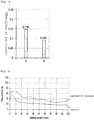
- FIG. 5 is a graph comparing a change of a pull-out force of an example of the present invention with that of a pull-out force of a comparative example.
- an example represents a case in which the inner binding tape 30 was formed of an unsintered polytetrafluoroethylene (PTFE) resin
- a comparative example represents a case in which a sintered fluororesin was used as a binding tape.
- a pull-out force is defined as a force N required due to friction with an outer core when an inner core was pulled out. That is, a friction force between an inner core and the outer core due to the inner binding tape 30 increases as the pull-out force is relatively large but decreases as the pull-out force decreases as the pull-out force is relatively small.
- the horizontal axis represents a length (mm) by which the inner core was pulled out
- the vertical axis represents a required force N.
- a required force decreases as a length by which the inner core is pulled out increases.
- the required force was 30 to 35 N when the length by which the inner core was pulled out was about 100 mm.
- the required force was lower than that of the comparative example.
- the required force was about 15 N and decreased to about 50% to 57% of that of the comparative example.
- At least one outer core 40 and at least one second insert 50 are provided on an outer side of the inner binding tape 30.
- the outer core 40 may be formed by the aggregate type and complex type processings.
- the outer core 40 may include a second conductor 43 with a plurality of second wire rods 42 twisted at a predetermined second pitch, a core part 45 with a plurality of second conductors 43 twisted at a predetermined third pitch, and a second insulating layer 44 provided on an outer side of the core part 45.
- the second pitch is 15 to 50 times an outer diameter of the second conductor 43
- the third pitch is 10 to 30 times an outer diameter of the core part 45.
- an increase rate of the yield strength of the second wire 42 of the outer core 40 is in a range of 1% to 30% and a resistance change rate (%) is in a range of 1% to 25%.
- the second insert 50 has an outer diameter corresponding to that of the outer core 40.
- the outer diameter of the second insert 50 may be 80 to 120% of that of the outer core 40.
- the second insert 50 may be formed by twisting elastic yarn, and the elastic yarn may be polyester yarn.
- the second insert 50 is substantially the same as the first insert 22 described above and thus a redundant description thereof will be omitted.
- outer cores 40 and one second insert 50 are illustrated in the drawing, the numbers of outer cores 40 and second inserts 50 are merely examples and may be appropriately changed.
- the outer binding tape 32 binds the outer core 40 and the second insert 50 and is formed of an unsintered fluororesin.
- the unsintered fluororesin may an unsintered polytetrafluoroethylene (PTFE) resin, and a coefficient of friction of the outer binding tape 32 may be in a range of 0.05 and 0.2.
- the outer binding tape 32 is substantially the same as the inner binding tape 30 described above and thus a redundant description thereof will be omitted.
- the shielding layer 60 is provided on an outer side of the outer binding tape 32.
- the shielding layer 60 may be in the form of a metal tape or braid formed of a material such as copper, aluminum, a copper alloy, or an aluminum alloy.
- the shielding layer 60 maintains communication characteristics of a communication cable by electromagnetic shielding or protects the cable from external impacts.
- the sheath 70 is provided on an outer side of the shielding layer 60.
- the sheath 70 may be an outermost layer of the cable 100 for a robot, and prevents the above-described inner components from being exposed to the outside and protects the inner components from external impacts.
- a sheath is molded by fully filled type extrusion but in this case, pressure marks may be caused on an inner conductor or a shielding layer due to the sheath after the extrusion.
- the sheath 70 is extrusion molded by tube type extrusion.
- the tube type extrusion is a process of inserting the inner components into the sheath 70 prepared in advance in the form of a tube and thus pressure marks may be prevented from occurring on the inner conductor or the shielding layer due to the sheath 70 after extrusion.
- an additional binding tape 34 may be further provided between the shielding layer 60 and the sheath 70.
- an internal frictional force may be further reduced when torsion, bending, or the like is applied to the cable 100 for a robot.
- the additional binding tape 34 is formed of an unsintered polytetrafluoroethylene (PTFE) resin and has a coefficient of friction between 0.05 and 0.2.
- PTFE polytetrafluoroethylene
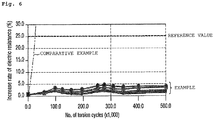
- FIG. 6 is a graph showing resistance change rates (%) according to the number of times of torsion of an example of the present invention and a comparative example.
- the example refers to a cable having the same configuration as that of FIG. 1 described above
- the comparative example refers to a cable in which high-density polyethylene (HDPE) or an EPDM was applied as an insert, a sintered fluororesin was applied as a binding tape, and a sheath was formed by fully filled type extrusion.
- the horizontal axis represents the number of times of torsion (x1000 times) and the vertical axis represents a resistance change rate (%).
- the resistance change rate exceeded 25% which was a reference value when the number of times of torsion reached approximately 20,000 to 25,000.
- the resistance change rate did not exceed 5.0% and was far less than 25% which was the reference value even when the number of times of torsion was greater than 50,000.
Landscapes
- Insulated Conductors (AREA)
- Yarns And Mechanical Finishing Of Yarns Or Ropes (AREA)
Applications Claiming Priority (2)
| Application Number | Priority Date | Filing Date | Title |
|---|---|---|---|
| KR1020170067918A KR102348281B1 (ko) | 2017-05-31 | 2017-05-31 | 로봇용 케이블 |
| PCT/KR2017/011830 WO2018221793A1 (ko) | 2017-05-31 | 2017-10-25 | 로봇용 케이블 |
Publications (3)
| Publication Number | Publication Date |
|---|---|
| EP3633692A1 true EP3633692A1 (de) | 2020-04-08 |
| EP3633692A4 EP3633692A4 (de) | 2021-02-24 |
| EP3633692B1 EP3633692B1 (de) | 2023-07-26 |
Family
ID=64454804
Family Applications (1)
| Application Number | Title | Priority Date | Filing Date |
|---|---|---|---|
| EP17911707.2A Active EP3633692B1 (de) | 2017-05-31 | 2017-10-25 | Kabel für roboter |
Country Status (5)
| Country | Link |
|---|---|
| EP (1) | EP3633692B1 (de) |
| JP (1) | JP2020520068A (de) |
| KR (1) | KR102348281B1 (de) |
| CN (1) | CN110663092B (de) |
| WO (1) | WO2018221793A1 (de) |
Families Citing this family (2)
| Publication number | Priority date | Publication date | Assignee | Title |
|---|---|---|---|---|
| KR20230140848A (ko) * | 2022-03-30 | 2023-10-10 | 엘에스전선 주식회사 | 음향 케이블용 도체 및 이를 포함하는 음향 케이블 |
| KR20250154716A (ko) | 2024-04-22 | 2025-10-29 | 엘에스전선 주식회사 | 우수한 비틀림 내구성을 갖는 로봇용 케이블 |
Family Cites Families (27)
| Publication number | Priority date | Publication date | Assignee | Title |
|---|---|---|---|---|
| JPS5692314U (de) * | 1979-12-18 | 1981-07-23 | ||
| JPS5864012U (ja) * | 1981-10-23 | 1983-04-30 | 日立電線株式会社 | 可撓性シ−ルド編組付多心ケ−ブル |
| DE3151235A1 (de) * | 1981-12-21 | 1983-06-30 | Siemens AG, 1000 Berlin und 8000 München | Flexible elektrische leitung |
| JPS63125312U (de) * | 1987-02-09 | 1988-08-16 | ||
| DE4004802A1 (de) * | 1990-02-13 | 1991-08-14 | Siemens Ag | Elektrisches kabel mit tragorgan und zwei konzentrisch angeordneten leitern |
| JPH05298943A (ja) * | 1992-04-17 | 1993-11-12 | Furukawa Electric Co Ltd:The | 複合ケーブル |
| US5408560A (en) * | 1993-02-26 | 1995-04-18 | N.V. Bekaert S.A. | Tensile member for communication cables |
| US6117083A (en) * | 1996-02-21 | 2000-09-12 | The Whitaker Corporation | Ultrasound imaging probe assembly |
| JP2003007145A (ja) * | 2001-06-20 | 2003-01-10 | Mitsubishi Cable Ind Ltd | 同軸ケーブル |
| JP4143087B2 (ja) * | 2005-12-20 | 2008-09-03 | 日立電線株式会社 | 極細絶縁線と同軸ケーブル及びその製造方法並びにこれを用いた多芯ケーブル |
| JP2007179985A (ja) * | 2005-12-28 | 2007-07-12 | Junkosha Co Ltd | 同軸ケーブル |
| CN101667473A (zh) * | 2008-09-04 | 2010-03-10 | 尼克桑斯公司 | 柔性电线 |
| JP5322755B2 (ja) * | 2009-04-23 | 2013-10-23 | 日立電線株式会社 | ケーブル |
| JP2012146591A (ja) * | 2011-01-14 | 2012-08-02 | Sumitomo Electric Ind Ltd | 多心ケーブル及びその製造方法 |
| KR101261320B1 (ko) * | 2011-05-03 | 2013-05-07 | 에쓰이에이치에프코리아 (주) | 광전 복합 케이블 |
| CN102568680A (zh) * | 2012-03-14 | 2012-07-11 | 四川川东电缆有限责任公司 | 一种风能电缆及制造方法 |
| JP6207142B2 (ja) * | 2012-10-01 | 2017-10-04 | 矢崎総業株式会社 | 電線 |
| JP2014191883A (ja) * | 2013-03-26 | 2014-10-06 | Hitachi Metals Ltd | Lanケーブル |
| CN203536074U (zh) * | 2013-11-11 | 2014-04-09 | 安徽金光神特种电缆有限公司 | 一种医疗用光电复合电缆 |
| CN104036874B (zh) * | 2014-05-22 | 2017-01-11 | 江苏亨通线缆科技有限公司 | 机器人用屏蔽型软电缆 |
| CN104036869B (zh) * | 2014-05-22 | 2017-05-31 | 江苏亨通线缆科技有限公司 | 抗拉伸耐疲劳型屏蔽软数据缆 |
| JP6245082B2 (ja) * | 2014-06-05 | 2017-12-13 | 日立金属株式会社 | 多対ケーブル |
| KR102244221B1 (ko) * | 2014-06-05 | 2021-04-26 | 엘에스전선 주식회사 | 이동용 광전력 신호 케이블 |
| CN104240818B (zh) * | 2014-09-03 | 2016-07-06 | 苏州科宝光电科技有限公司 | 断层扫描成像医疗器械用的高柔电缆 |
| WO2016084112A1 (ja) * | 2014-11-25 | 2016-06-02 | 昭和電線ケーブルシステム株式会社 | 複合ケーブル |
| JP6114331B2 (ja) * | 2015-04-06 | 2017-04-12 | 矢崎総業株式会社 | 耐屈曲電線及びワイヤハーネス |
| US10043599B2 (en) * | 2015-04-24 | 2018-08-07 | Sumitomo Electric Industries, Ltd. | Multi-core cable |
-
2017
- 2017-05-31 KR KR1020170067918A patent/KR102348281B1/ko active Active
- 2017-10-25 JP JP2019562583A patent/JP2020520068A/ja active Pending
- 2017-10-25 CN CN201780090794.7A patent/CN110663092B/zh active Active
- 2017-10-25 EP EP17911707.2A patent/EP3633692B1/de active Active
- 2017-10-25 WO PCT/KR2017/011830 patent/WO2018221793A1/ko not_active Ceased
Also Published As
| Publication number | Publication date |
|---|---|
| EP3633692B1 (de) | 2023-07-26 |
| KR102348281B1 (ko) | 2022-01-06 |
| EP3633692A4 (de) | 2021-02-24 |
| KR20180131219A (ko) | 2018-12-10 |
| CN110663092A (zh) | 2020-01-07 |
| JP2020520068A (ja) | 2020-07-02 |
| CN110663092B (zh) | 2021-04-23 |
| WO2018221793A1 (ko) | 2018-12-06 |
Similar Documents
| Publication | Publication Date | Title |
|---|---|---|
| US10217548B2 (en) | Coaxial cable | |
| CN109841314B (zh) | 带有编织屏蔽的电缆 | |
| EP2021407B1 (de) | Kabel und herstellungsverfahren dafür | |
| US7164078B2 (en) | Abrasion-resistant jacket | |
| JP6893496B2 (ja) | 同軸ケーブル | |
| US20130126209A1 (en) | Forward twisted profiled insulation for lan cables | |
| EP3633692B1 (de) | Kabel für roboter | |
| JP7640216B2 (ja) | 通信ケーブル | |
| US10269468B1 (en) | Cable with braided shield | |
| CN102810356B (zh) | 使用二氧化钛降低数据通信线缆中时滞的氟化乙烯丙烯共聚物(fep)改性 | |
| WO2018043392A1 (ja) | ケーブル | |
| KR102735852B1 (ko) | 우수한 내구성을 갖는 로봇용 케이블 | |
| EP3282454A1 (de) | Starkstromkabel mit flexiblen sektoralen leitern | |
| CN204946567U (zh) | 一种机器人本体用信号电缆 | |
| JP2024086662A (ja) | 通信用電線 | |
| CN214588110U (zh) | 电缆 | |
| KR102579741B1 (ko) | 절연전선 및 다심 케이블 | |
| KR102722675B1 (ko) | 우수한 유연성을 갖는 케이블 | |
| CN223501575U (zh) | 一种新型耐磨耐压拖链电缆 | |
| US20240274317A1 (en) | Flat cable | |
| JP2013235704A (ja) | 移動機械用の平型ケーブル | |
| US10864550B2 (en) | Subsea umbilical | |
| DE112023006284T5 (de) | Kabel | |
| KR20230159659A (ko) | 무빙 케이블 유닛 | |
| KR20250168117A (ko) | 유연한 섹터 케이블 및 그 제조 방법 |
Legal Events
| Date | Code | Title | Description |
|---|---|---|---|
| STAA | Information on the status of an ep patent application or granted ep patent |
Free format text: STATUS: THE INTERNATIONAL PUBLICATION HAS BEEN MADE |
|
| PUAI | Public reference made under article 153(3) epc to a published international application that has entered the european phase |
Free format text: ORIGINAL CODE: 0009012 |
|
| STAA | Information on the status of an ep patent application or granted ep patent |
Free format text: STATUS: REQUEST FOR EXAMINATION WAS MADE |
|
| 17P | Request for examination filed |
Effective date: 20191113 |
|
| AK | Designated contracting states |
Kind code of ref document: A1 Designated state(s): AL AT BE BG CH CY CZ DE DK EE ES FI FR GB GR HR HU IE IS IT LI LT LU LV MC MK MT NL NO PL PT RO RS SE SI SK SM TR |
|
| AX | Request for extension of the european patent |
Extension state: BA ME |
|
| DAV | Request for validation of the european patent (deleted) | ||
| DAX | Request for extension of the european patent (deleted) | ||
| A4 | Supplementary search report drawn up and despatched |
Effective date: 20210121 |
|
| RIC1 | Information provided on ipc code assigned before grant |
Ipc: H01B 7/18 20060101ALI20210115BHEP Ipc: H01B 7/02 20060101ALI20210115BHEP Ipc: H01B 9/00 20060101ALI20210115BHEP Ipc: H01B 9/02 20060101AFI20210115BHEP Ipc: H01B 7/17 20060101ALI20210115BHEP |
|
| STAA | Information on the status of an ep patent application or granted ep patent |
Free format text: STATUS: EXAMINATION IS IN PROGRESS |
|
| 17Q | First examination report despatched |
Effective date: 20220120 |
|
| GRAP | Despatch of communication of intention to grant a patent |
Free format text: ORIGINAL CODE: EPIDOSNIGR1 |
|
| STAA | Information on the status of an ep patent application or granted ep patent |
Free format text: STATUS: GRANT OF PATENT IS INTENDED |
|
| INTG | Intention to grant announced |
Effective date: 20230222 |
|
| GRAS | Grant fee paid |
Free format text: ORIGINAL CODE: EPIDOSNIGR3 |
|
| GRAA | (expected) grant |
Free format text: ORIGINAL CODE: 0009210 |
|
| STAA | Information on the status of an ep patent application or granted ep patent |
Free format text: STATUS: THE PATENT HAS BEEN GRANTED |
|
| AK | Designated contracting states |
Kind code of ref document: B1 Designated state(s): AL AT BE BG CH CY CZ DE DK EE ES FI FR GB GR HR HU IE IS IT LI LT LU LV MC MK MT NL NO PL PT RO RS SE SI SK SM TR |
|
| REG | Reference to a national code |
Ref country code: CH Ref legal event code: EP |
|
| REG | Reference to a national code |
Ref country code: DE Ref legal event code: R096 Ref document number: 602017071978 Country of ref document: DE |
|
| REG | Reference to a national code |
Ref country code: IE Ref legal event code: FG4D |
|
| REG | Reference to a national code |
Ref country code: LT Ref legal event code: MG9D |
|
| REG | Reference to a national code |
Ref country code: NL Ref legal event code: MP Effective date: 20230726 |
|
| REG | Reference to a national code |
Ref country code: AT Ref legal event code: MK05 Ref document number: 1592926 Country of ref document: AT Kind code of ref document: T Effective date: 20230726 |
|
| PG25 | Lapsed in a contracting state [announced via postgrant information from national office to epo] |
Ref country code: NL Free format text: LAPSE BECAUSE OF FAILURE TO SUBMIT A TRANSLATION OF THE DESCRIPTION OR TO PAY THE FEE WITHIN THE PRESCRIBED TIME-LIMIT Effective date: 20230726 |
|
| PG25 | Lapsed in a contracting state [announced via postgrant information from national office to epo] |
Ref country code: GR Free format text: LAPSE BECAUSE OF FAILURE TO SUBMIT A TRANSLATION OF THE DESCRIPTION OR TO PAY THE FEE WITHIN THE PRESCRIBED TIME-LIMIT Effective date: 20231027 |
|
| PG25 | Lapsed in a contracting state [announced via postgrant information from national office to epo] |
Ref country code: IS Free format text: LAPSE BECAUSE OF FAILURE TO SUBMIT A TRANSLATION OF THE DESCRIPTION OR TO PAY THE FEE WITHIN THE PRESCRIBED TIME-LIMIT Effective date: 20231126 |
|
| PG25 | Lapsed in a contracting state [announced via postgrant information from national office to epo] |
Ref country code: SE Free format text: LAPSE BECAUSE OF FAILURE TO SUBMIT A TRANSLATION OF THE DESCRIPTION OR TO PAY THE FEE WITHIN THE PRESCRIBED TIME-LIMIT Effective date: 20230726 Ref country code: RS Free format text: LAPSE BECAUSE OF FAILURE TO SUBMIT A TRANSLATION OF THE DESCRIPTION OR TO PAY THE FEE WITHIN THE PRESCRIBED TIME-LIMIT Effective date: 20230726 Ref country code: PT Free format text: LAPSE BECAUSE OF FAILURE TO SUBMIT A TRANSLATION OF THE DESCRIPTION OR TO PAY THE FEE WITHIN THE PRESCRIBED TIME-LIMIT Effective date: 20231127 Ref country code: NO Free format text: LAPSE BECAUSE OF FAILURE TO SUBMIT A TRANSLATION OF THE DESCRIPTION OR TO PAY THE FEE WITHIN THE PRESCRIBED TIME-LIMIT Effective date: 20231026 Ref country code: LV Free format text: LAPSE BECAUSE OF FAILURE TO SUBMIT A TRANSLATION OF THE DESCRIPTION OR TO PAY THE FEE WITHIN THE PRESCRIBED TIME-LIMIT Effective date: 20230726 Ref country code: LT Free format text: LAPSE BECAUSE OF FAILURE TO SUBMIT A TRANSLATION OF THE DESCRIPTION OR TO PAY THE FEE WITHIN THE PRESCRIBED TIME-LIMIT Effective date: 20230726 Ref country code: IS Free format text: LAPSE BECAUSE OF FAILURE TO SUBMIT A TRANSLATION OF THE DESCRIPTION OR TO PAY THE FEE WITHIN THE PRESCRIBED TIME-LIMIT Effective date: 20231126 Ref country code: HR Free format text: LAPSE BECAUSE OF FAILURE TO SUBMIT A TRANSLATION OF THE DESCRIPTION OR TO PAY THE FEE WITHIN THE PRESCRIBED TIME-LIMIT Effective date: 20230726 Ref country code: GR Free format text: LAPSE BECAUSE OF FAILURE TO SUBMIT A TRANSLATION OF THE DESCRIPTION OR TO PAY THE FEE WITHIN THE PRESCRIBED TIME-LIMIT Effective date: 20231027 Ref country code: FI Free format text: LAPSE BECAUSE OF FAILURE TO SUBMIT A TRANSLATION OF THE DESCRIPTION OR TO PAY THE FEE WITHIN THE PRESCRIBED TIME-LIMIT Effective date: 20230726 Ref country code: AT Free format text: LAPSE BECAUSE OF FAILURE TO SUBMIT A TRANSLATION OF THE DESCRIPTION OR TO PAY THE FEE WITHIN THE PRESCRIBED TIME-LIMIT Effective date: 20230726 |
|
| PG25 | Lapsed in a contracting state [announced via postgrant information from national office to epo] |
Ref country code: PL Free format text: LAPSE BECAUSE OF FAILURE TO SUBMIT A TRANSLATION OF THE DESCRIPTION OR TO PAY THE FEE WITHIN THE PRESCRIBED TIME-LIMIT Effective date: 20230726 |
|
| PG25 | Lapsed in a contracting state [announced via postgrant information from national office to epo] |
Ref country code: ES Free format text: LAPSE BECAUSE OF FAILURE TO SUBMIT A TRANSLATION OF THE DESCRIPTION OR TO PAY THE FEE WITHIN THE PRESCRIBED TIME-LIMIT Effective date: 20230726 |
|
| REG | Reference to a national code |
Ref country code: DE Ref legal event code: R097 Ref document number: 602017071978 Country of ref document: DE |
|
| PG25 | Lapsed in a contracting state [announced via postgrant information from national office to epo] |
Ref country code: SM Free format text: LAPSE BECAUSE OF FAILURE TO SUBMIT A TRANSLATION OF THE DESCRIPTION OR TO PAY THE FEE WITHIN THE PRESCRIBED TIME-LIMIT Effective date: 20230726 Ref country code: RO Free format text: LAPSE BECAUSE OF FAILURE TO SUBMIT A TRANSLATION OF THE DESCRIPTION OR TO PAY THE FEE WITHIN THE PRESCRIBED TIME-LIMIT Effective date: 20230726 Ref country code: ES Free format text: LAPSE BECAUSE OF FAILURE TO SUBMIT A TRANSLATION OF THE DESCRIPTION OR TO PAY THE FEE WITHIN THE PRESCRIBED TIME-LIMIT Effective date: 20230726 Ref country code: EE Free format text: LAPSE BECAUSE OF FAILURE TO SUBMIT A TRANSLATION OF THE DESCRIPTION OR TO PAY THE FEE WITHIN THE PRESCRIBED TIME-LIMIT Effective date: 20230726 Ref country code: DK Free format text: LAPSE BECAUSE OF FAILURE TO SUBMIT A TRANSLATION OF THE DESCRIPTION OR TO PAY THE FEE WITHIN THE PRESCRIBED TIME-LIMIT Effective date: 20230726 Ref country code: CZ Free format text: LAPSE BECAUSE OF FAILURE TO SUBMIT A TRANSLATION OF THE DESCRIPTION OR TO PAY THE FEE WITHIN THE PRESCRIBED TIME-LIMIT Effective date: 20230726 Ref country code: SK Free format text: LAPSE BECAUSE OF FAILURE TO SUBMIT A TRANSLATION OF THE DESCRIPTION OR TO PAY THE FEE WITHIN THE PRESCRIBED TIME-LIMIT Effective date: 20230726 |
|
| PG25 | Lapsed in a contracting state [announced via postgrant information from national office to epo] |
Ref country code: IT Free format text: LAPSE BECAUSE OF FAILURE TO SUBMIT A TRANSLATION OF THE DESCRIPTION OR TO PAY THE FEE WITHIN THE PRESCRIBED TIME-LIMIT Effective date: 20230726 Ref country code: MC Free format text: LAPSE BECAUSE OF FAILURE TO SUBMIT A TRANSLATION OF THE DESCRIPTION OR TO PAY THE FEE WITHIN THE PRESCRIBED TIME-LIMIT Effective date: 20230726 |
|
| PLBE | No opposition filed within time limit |
Free format text: ORIGINAL CODE: 0009261 |
|
| REG | Reference to a national code |
Ref country code: CH Ref legal event code: PL |
|
| STAA | Information on the status of an ep patent application or granted ep patent |
Free format text: STATUS: NO OPPOSITION FILED WITHIN TIME LIMIT |
|
| REG | Reference to a national code |
Ref country code: BE Ref legal event code: MM Effective date: 20231031 |
|
| PG25 | Lapsed in a contracting state [announced via postgrant information from national office to epo] |
Ref country code: LU Free format text: LAPSE BECAUSE OF NON-PAYMENT OF DUE FEES Effective date: 20231025 |
|
| GBPC | Gb: european patent ceased through non-payment of renewal fee |
Effective date: 20231026 |
|
| PG25 | Lapsed in a contracting state [announced via postgrant information from national office to epo] |
Ref country code: LU Free format text: LAPSE BECAUSE OF NON-PAYMENT OF DUE FEES Effective date: 20231025 |
|
| 26N | No opposition filed |
Effective date: 20240429 |
|
| PG25 | Lapsed in a contracting state [announced via postgrant information from national office to epo] |
Ref country code: GB Free format text: LAPSE BECAUSE OF NON-PAYMENT OF DUE FEES Effective date: 20231026 |
|
| PG25 | Lapsed in a contracting state [announced via postgrant information from national office to epo] |
Ref country code: CH Free format text: LAPSE BECAUSE OF NON-PAYMENT OF DUE FEES Effective date: 20231031 |
|
| PG25 | Lapsed in a contracting state [announced via postgrant information from national office to epo] |
Ref country code: GB Free format text: LAPSE BECAUSE OF NON-PAYMENT OF DUE FEES Effective date: 20231026 Ref country code: FR Free format text: LAPSE BECAUSE OF NON-PAYMENT OF DUE FEES Effective date: 20231031 Ref country code: CH Free format text: LAPSE BECAUSE OF NON-PAYMENT OF DUE FEES Effective date: 20231031 Ref country code: SI Free format text: LAPSE BECAUSE OF FAILURE TO SUBMIT A TRANSLATION OF THE DESCRIPTION OR TO PAY THE FEE WITHIN THE PRESCRIBED TIME-LIMIT Effective date: 20230726 |
|
| PG25 | Lapsed in a contracting state [announced via postgrant information from national office to epo] |
Ref country code: BE Free format text: LAPSE BECAUSE OF NON-PAYMENT OF DUE FEES Effective date: 20231031 |
|
| PG25 | Lapsed in a contracting state [announced via postgrant information from national office to epo] |
Ref country code: IE Free format text: LAPSE BECAUSE OF NON-PAYMENT OF DUE FEES Effective date: 20231025 |
|
| PG25 | Lapsed in a contracting state [announced via postgrant information from national office to epo] |
Ref country code: IE Free format text: LAPSE BECAUSE OF NON-PAYMENT OF DUE FEES Effective date: 20231025 |
|
| PG25 | Lapsed in a contracting state [announced via postgrant information from national office to epo] |
Ref country code: BG Free format text: LAPSE BECAUSE OF FAILURE TO SUBMIT A TRANSLATION OF THE DESCRIPTION OR TO PAY THE FEE WITHIN THE PRESCRIBED TIME-LIMIT Effective date: 20230726 |
|
| PG25 | Lapsed in a contracting state [announced via postgrant information from national office to epo] |
Ref country code: BG Free format text: LAPSE BECAUSE OF FAILURE TO SUBMIT A TRANSLATION OF THE DESCRIPTION OR TO PAY THE FEE WITHIN THE PRESCRIBED TIME-LIMIT Effective date: 20230726 |
|
| PG25 | Lapsed in a contracting state [announced via postgrant information from national office to epo] |
Ref country code: CY Free format text: LAPSE BECAUSE OF FAILURE TO SUBMIT A TRANSLATION OF THE DESCRIPTION OR TO PAY THE FEE WITHIN THE PRESCRIBED TIME-LIMIT; INVALID AB INITIO Effective date: 20171025 |
|
| PG25 | Lapsed in a contracting state [announced via postgrant information from national office to epo] |
Ref country code: HU Free format text: LAPSE BECAUSE OF FAILURE TO SUBMIT A TRANSLATION OF THE DESCRIPTION OR TO PAY THE FEE WITHIN THE PRESCRIBED TIME-LIMIT; INVALID AB INITIO Effective date: 20171025 |
|
| PG25 | Lapsed in a contracting state [announced via postgrant information from national office to epo] |
Ref country code: TR Free format text: LAPSE BECAUSE OF FAILURE TO SUBMIT A TRANSLATION OF THE DESCRIPTION OR TO PAY THE FEE WITHIN THE PRESCRIBED TIME-LIMIT Effective date: 20230726 |
|
| PGFP | Annual fee paid to national office [announced via postgrant information from national office to epo] |
Ref country code: DE Payment date: 20251021 Year of fee payment: 9 |