EP3633283B1 - Klimaanlage und steuerungsverfahren dafür - Google Patents
Klimaanlage und steuerungsverfahren dafür Download PDFInfo
- Publication number
- EP3633283B1 EP3633283B1 EP18824350.5A EP18824350A EP3633283B1 EP 3633283 B1 EP3633283 B1 EP 3633283B1 EP 18824350 A EP18824350 A EP 18824350A EP 3633283 B1 EP3633283 B1 EP 3633283B1
- Authority
- EP
- European Patent Office
- Prior art keywords
- temperature
- compressor
- heat exchanger
- frequency
- indoor heat
- Prior art date
- Legal status (The legal status is an assumption and is not a legal conclusion. Google has not performed a legal analysis and makes no representation as to the accuracy of the status listed.)
- Active
Links
Images



Classifications
-
- F—MECHANICAL ENGINEERING; LIGHTING; HEATING; WEAPONS; BLASTING
- F25—REFRIGERATION OR COOLING; COMBINED HEATING AND REFRIGERATION SYSTEMS; HEAT PUMP SYSTEMS; MANUFACTURE OR STORAGE OF ICE; LIQUEFACTION SOLIDIFICATION OF GASES
- F25B—REFRIGERATION MACHINES, PLANTS OR SYSTEMS; COMBINED HEATING AND REFRIGERATION SYSTEMS; HEAT PUMP SYSTEMS
- F25B49/00—Arrangement or mounting of control or safety devices
- F25B49/02—Arrangement or mounting of control or safety devices for compression type machines, plants or systems
-
- F—MECHANICAL ENGINEERING; LIGHTING; HEATING; WEAPONS; BLASTING
- F24—HEATING; RANGES; VENTILATING
- F24F—AIR-CONDITIONING; AIR-HUMIDIFICATION; VENTILATION; USE OF AIR CURRENTS FOR SCREENING
- F24F3/00—Air-conditioning systems in which conditioned primary air is supplied from one or more central stations to distributing units in the rooms or spaces where it may receive secondary treatment; Apparatus specially designed for such systems
- F24F3/06—Air-conditioning systems in which conditioned primary air is supplied from one or more central stations to distributing units in the rooms or spaces where it may receive secondary treatment; Apparatus specially designed for such systems characterised by the arrangements for the supply of heat-exchange fluid for the subsequent treatment of primary air in the room units
-
- F—MECHANICAL ENGINEERING; LIGHTING; HEATING; WEAPONS; BLASTING
- F24—HEATING; RANGES; VENTILATING
- F24F—AIR-CONDITIONING; AIR-HUMIDIFICATION; VENTILATION; USE OF AIR CURRENTS FOR SCREENING
- F24F11/00—Control or safety arrangements
- F24F11/0008—Control or safety arrangements for air-humidification
-
- F—MECHANICAL ENGINEERING; LIGHTING; HEATING; WEAPONS; BLASTING
- F24—HEATING; RANGES; VENTILATING
- F24F—AIR-CONDITIONING; AIR-HUMIDIFICATION; VENTILATION; USE OF AIR CURRENTS FOR SCREENING
- F24F1/00—Room units for air-conditioning, e.g. separate or self-contained units or units receiving primary air from a central station
- F24F1/0007—Indoor units, e.g. fan coil units
- F24F1/00075—Indoor units, e.g. fan coil units receiving air from a central station
-
- F—MECHANICAL ENGINEERING; LIGHTING; HEATING; WEAPONS; BLASTING
- F24—HEATING; RANGES; VENTILATING
- F24F—AIR-CONDITIONING; AIR-HUMIDIFICATION; VENTILATION; USE OF AIR CURRENTS FOR SCREENING
- F24F1/00—Room units for air-conditioning, e.g. separate or self-contained units or units receiving primary air from a central station
- F24F1/0007—Indoor units, e.g. fan coil units
- F24F1/0087—Indoor units, e.g. fan coil units with humidification means
-
- F—MECHANICAL ENGINEERING; LIGHTING; HEATING; WEAPONS; BLASTING
- F24—HEATING; RANGES; VENTILATING
- F24F—AIR-CONDITIONING; AIR-HUMIDIFICATION; VENTILATION; USE OF AIR CURRENTS FOR SCREENING
- F24F11/00—Control or safety arrangements
- F24F11/30—Control or safety arrangements for purposes related to the operation of the system, e.g. for safety or monitoring
-
- F—MECHANICAL ENGINEERING; LIGHTING; HEATING; WEAPONS; BLASTING
- F24—HEATING; RANGES; VENTILATING
- F24F—AIR-CONDITIONING; AIR-HUMIDIFICATION; VENTILATION; USE OF AIR CURRENTS FOR SCREENING
- F24F11/00—Control or safety arrangements
- F24F11/30—Control or safety arrangements for purposes related to the operation of the system, e.g. for safety or monitoring
- F24F11/49—Control or safety arrangements for purposes related to the operation of the system, e.g. for safety or monitoring ensuring correct operation, e.g. by trial operation or configuration checks
-
- F—MECHANICAL ENGINEERING; LIGHTING; HEATING; WEAPONS; BLASTING
- F24—HEATING; RANGES; VENTILATING
- F24F—AIR-CONDITIONING; AIR-HUMIDIFICATION; VENTILATION; USE OF AIR CURRENTS FOR SCREENING
- F24F11/00—Control or safety arrangements
- F24F11/62—Control or safety arrangements characterised by the type of control or by internal processing, e.g. using fuzzy logic, adaptive control or estimation of values
-
- F—MECHANICAL ENGINEERING; LIGHTING; HEATING; WEAPONS; BLASTING
- F24—HEATING; RANGES; VENTILATING
- F24F—AIR-CONDITIONING; AIR-HUMIDIFICATION; VENTILATION; USE OF AIR CURRENTS FOR SCREENING
- F24F11/00—Control or safety arrangements
- F24F11/62—Control or safety arrangements characterised by the type of control or by internal processing, e.g. using fuzzy logic, adaptive control or estimation of values
- F24F11/63—Electronic processing
-
- F—MECHANICAL ENGINEERING; LIGHTING; HEATING; WEAPONS; BLASTING
- F24—HEATING; RANGES; VENTILATING
- F24F—AIR-CONDITIONING; AIR-HUMIDIFICATION; VENTILATION; USE OF AIR CURRENTS FOR SCREENING
- F24F11/00—Control or safety arrangements
- F24F11/70—Control systems characterised by their outputs; Constructional details thereof
- F24F11/80—Control systems characterised by their outputs; Constructional details thereof for controlling the temperature of the supplied air
- F24F11/83—Control systems characterised by their outputs; Constructional details thereof for controlling the temperature of the supplied air by controlling the supply of heat-exchange fluids to heat-exchangers
- F24F11/84—Control systems characterised by their outputs; Constructional details thereof for controlling the temperature of the supplied air by controlling the supply of heat-exchange fluids to heat-exchangers using valves
-
- F—MECHANICAL ENGINEERING; LIGHTING; HEATING; WEAPONS; BLASTING
- F24—HEATING; RANGES; VENTILATING
- F24F—AIR-CONDITIONING; AIR-HUMIDIFICATION; VENTILATION; USE OF AIR CURRENTS FOR SCREENING
- F24F11/00—Control or safety arrangements
- F24F11/70—Control systems characterised by their outputs; Constructional details thereof
- F24F11/80—Control systems characterised by their outputs; Constructional details thereof for controlling the temperature of the supplied air
- F24F11/86—Control systems characterised by their outputs; Constructional details thereof for controlling the temperature of the supplied air by controlling compressors within refrigeration or heat pump circuits
-
- F—MECHANICAL ENGINEERING; LIGHTING; HEATING; WEAPONS; BLASTING
- F25—REFRIGERATION OR COOLING; COMBINED HEATING AND REFRIGERATION SYSTEMS; HEAT PUMP SYSTEMS; MANUFACTURE OR STORAGE OF ICE; LIQUEFACTION SOLIDIFICATION OF GASES
- F25B—REFRIGERATION MACHINES, PLANTS OR SYSTEMS; COMBINED HEATING AND REFRIGERATION SYSTEMS; HEAT PUMP SYSTEMS
- F25B49/00—Arrangement or mounting of control or safety devices
- F25B49/02—Arrangement or mounting of control or safety devices for compression type machines, plants or systems
- F25B49/022—Compressor control arrangements
-
- F—MECHANICAL ENGINEERING; LIGHTING; HEATING; WEAPONS; BLASTING
- F24—HEATING; RANGES; VENTILATING
- F24F—AIR-CONDITIONING; AIR-HUMIDIFICATION; VENTILATION; USE OF AIR CURRENTS FOR SCREENING
- F24F2110/00—Control inputs relating to air properties
- F24F2110/10—Temperature
-
- F—MECHANICAL ENGINEERING; LIGHTING; HEATING; WEAPONS; BLASTING
- F24—HEATING; RANGES; VENTILATING
- F24F—AIR-CONDITIONING; AIR-HUMIDIFICATION; VENTILATION; USE OF AIR CURRENTS FOR SCREENING
- F24F2110/00—Control inputs relating to air properties
- F24F2110/10—Temperature
- F24F2110/12—Temperature of the outside air
-
- F—MECHANICAL ENGINEERING; LIGHTING; HEATING; WEAPONS; BLASTING
- F24—HEATING; RANGES; VENTILATING
- F24F—AIR-CONDITIONING; AIR-HUMIDIFICATION; VENTILATION; USE OF AIR CURRENTS FOR SCREENING
- F24F2110/00—Control inputs relating to air properties
- F24F2110/20—Humidity
-
- F—MECHANICAL ENGINEERING; LIGHTING; HEATING; WEAPONS; BLASTING
- F25—REFRIGERATION OR COOLING; COMBINED HEATING AND REFRIGERATION SYSTEMS; HEAT PUMP SYSTEMS; MANUFACTURE OR STORAGE OF ICE; LIQUEFACTION SOLIDIFICATION OF GASES
- F25B—REFRIGERATION MACHINES, PLANTS OR SYSTEMS; COMBINED HEATING AND REFRIGERATION SYSTEMS; HEAT PUMP SYSTEMS
- F25B13/00—Compression machines, plants or systems, with reversible cycle
-
- F—MECHANICAL ENGINEERING; LIGHTING; HEATING; WEAPONS; BLASTING
- F25—REFRIGERATION OR COOLING; COMBINED HEATING AND REFRIGERATION SYSTEMS; HEAT PUMP SYSTEMS; MANUFACTURE OR STORAGE OF ICE; LIQUEFACTION SOLIDIFICATION OF GASES
- F25B—REFRIGERATION MACHINES, PLANTS OR SYSTEMS; COMBINED HEATING AND REFRIGERATION SYSTEMS; HEAT PUMP SYSTEMS
- F25B2313/00—Compression machines, plants or systems with reversible cycle not otherwise provided for
- F25B2313/029—Control issues
- F25B2313/0294—Control issues related to the outdoor fan, e.g. controlling speed
-
- F—MECHANICAL ENGINEERING; LIGHTING; HEATING; WEAPONS; BLASTING
- F25—REFRIGERATION OR COOLING; COMBINED HEATING AND REFRIGERATION SYSTEMS; HEAT PUMP SYSTEMS; MANUFACTURE OR STORAGE OF ICE; LIQUEFACTION SOLIDIFICATION OF GASES
- F25B—REFRIGERATION MACHINES, PLANTS OR SYSTEMS; COMBINED HEATING AND REFRIGERATION SYSTEMS; HEAT PUMP SYSTEMS
- F25B2500/00—Problems to be solved
- F25B2500/19—Calculation of parameters
-
- F—MECHANICAL ENGINEERING; LIGHTING; HEATING; WEAPONS; BLASTING
- F25—REFRIGERATION OR COOLING; COMBINED HEATING AND REFRIGERATION SYSTEMS; HEAT PUMP SYSTEMS; MANUFACTURE OR STORAGE OF ICE; LIQUEFACTION SOLIDIFICATION OF GASES
- F25B—REFRIGERATION MACHINES, PLANTS OR SYSTEMS; COMBINED HEATING AND REFRIGERATION SYSTEMS; HEAT PUMP SYSTEMS
- F25B2600/00—Control issues
- F25B2600/02—Compressor control
- F25B2600/025—Compressor control by controlling speed
- F25B2600/0253—Compressor control by controlling speed with variable speed
-
- F—MECHANICAL ENGINEERING; LIGHTING; HEATING; WEAPONS; BLASTING
- F25—REFRIGERATION OR COOLING; COMBINED HEATING AND REFRIGERATION SYSTEMS; HEAT PUMP SYSTEMS; MANUFACTURE OR STORAGE OF ICE; LIQUEFACTION SOLIDIFICATION OF GASES
- F25B—REFRIGERATION MACHINES, PLANTS OR SYSTEMS; COMBINED HEATING AND REFRIGERATION SYSTEMS; HEAT PUMP SYSTEMS
- F25B2600/00—Control issues
- F25B2600/25—Control of valves
- F25B2600/2513—Expansion valves
-
- F—MECHANICAL ENGINEERING; LIGHTING; HEATING; WEAPONS; BLASTING
- F25—REFRIGERATION OR COOLING; COMBINED HEATING AND REFRIGERATION SYSTEMS; HEAT PUMP SYSTEMS; MANUFACTURE OR STORAGE OF ICE; LIQUEFACTION SOLIDIFICATION OF GASES
- F25B—REFRIGERATION MACHINES, PLANTS OR SYSTEMS; COMBINED HEATING AND REFRIGERATION SYSTEMS; HEAT PUMP SYSTEMS
- F25B2700/00—Sensing or detecting of parameters; Sensors therefor
- F25B2700/02—Humidity
-
- F—MECHANICAL ENGINEERING; LIGHTING; HEATING; WEAPONS; BLASTING
- F25—REFRIGERATION OR COOLING; COMBINED HEATING AND REFRIGERATION SYSTEMS; HEAT PUMP SYSTEMS; MANUFACTURE OR STORAGE OF ICE; LIQUEFACTION SOLIDIFICATION OF GASES
- F25B—REFRIGERATION MACHINES, PLANTS OR SYSTEMS; COMBINED HEATING AND REFRIGERATION SYSTEMS; HEAT PUMP SYSTEMS
- F25B2700/00—Sensing or detecting of parameters; Sensors therefor
- F25B2700/21—Temperatures
- F25B2700/2104—Temperatures of an indoor room or compartment
-
- F—MECHANICAL ENGINEERING; LIGHTING; HEATING; WEAPONS; BLASTING
- F25—REFRIGERATION OR COOLING; COMBINED HEATING AND REFRIGERATION SYSTEMS; HEAT PUMP SYSTEMS; MANUFACTURE OR STORAGE OF ICE; LIQUEFACTION SOLIDIFICATION OF GASES
- F25B—REFRIGERATION MACHINES, PLANTS OR SYSTEMS; COMBINED HEATING AND REFRIGERATION SYSTEMS; HEAT PUMP SYSTEMS
- F25B2700/00—Sensing or detecting of parameters; Sensors therefor
- F25B2700/21—Temperatures
- F25B2700/2106—Temperatures of fresh outdoor air
-
- Y—GENERAL TAGGING OF NEW TECHNOLOGICAL DEVELOPMENTS; GENERAL TAGGING OF CROSS-SECTIONAL TECHNOLOGIES SPANNING OVER SEVERAL SECTIONS OF THE IPC; TECHNICAL SUBJECTS COVERED BY FORMER USPC CROSS-REFERENCE ART COLLECTIONS [XRACs] AND DIGESTS
- Y02—TECHNOLOGIES OR APPLICATIONS FOR MITIGATION OR ADAPTATION AGAINST CLIMATE CHANGE
- Y02B—CLIMATE CHANGE MITIGATION TECHNOLOGIES RELATED TO BUILDINGS, e.g. HOUSING, HOUSE APPLIANCES OR RELATED END-USER APPLICATIONS
- Y02B30/00—Energy efficient heating, ventilation or air conditioning [HVAC]
- Y02B30/70—Efficient control or regulation technologies, e.g. for control of refrigerant flow, motor or heating
Definitions
- Embodiments of the disclosure relate to an air conditioner and a method of controlling the air conditioner.
- An air conditioner is an apparatus that cools or heats indoor air.
- the air conditioner performs cooling by using the characteristic of absorbing the surrounding heat when a liquid refrigerant vaporizes, and performs heating by using the characteristic of releasing heat when a gaseous refrigerant liquefies.
- a typical air conditioner generally connects a single indoor unit to a single outdoor unit.
- demand for a system air conditioner which connects a plurality of the indoor units having various types and capacities to the single outdoor unit is increasing.
- the dehumidification is controlled using a fixed constant compressor frequency that is obtained by calculating a temperature difference between the indoor set temperature and the indoor suction temperature and a threshold value by the indoor and outdoor temperatures.
- the humidity control of the air conditioner is an indirect control, which removes only sensible heat and does not remove latent heat (humidity), and thus the relative humidity may be high to a user even after reaching a requested set temperature.
- JP 5975937 discloses an air conditioning apparatus.
- JP 2002286275 discloses an air conditioner.
- US 5345776 discloses an air conditioner.
- JP 2004101164 discloses an air conditioner.
- One aspect provides an air conditioner and a method of controlling the air conditioner to directly control indoor temperature and humidity to provide an optimal temperature and humidity for a user to feel comfortable.
- an air conditioner as set out in claim 1.
- the controller may calculate a frequency change amount of the compressor by applying the temperature difference between the dew point temperature and the indoor heat exchanger temperature and the change amount of the indoor heat exchanger temperature to a compressor fuzzy table.
- the compressor fuzzy table may be configured to decrease the compressor frequency when the indoor heat exchanger temperature is gradually lowered or falls below the dew point temperature, and increase the compressor frequency when the indoor heat exchanger is gradually increased or exceeds the dew point temperature.
- the controller may calculate the current compressor frequency based on a previous compressor frequency and the frequency change amount of the compressor, and may control a rotation speed of an outdoor fan using the calculated current compressor frequency and an outdoor temperature.
- the controller may calculate the current compressor frequency based on a previous compressor frequency and the change amount in the frequency of the compressor, and may control an electronic expansion valve using the calculated current compressor frequency and room temperature and outdoor temperature.
- the controller may control to maintain the indoor heat exchanger temperature to be lower than the dew point temperature.
- a method of controlling an air conditioner may comprise calculating a dew point temperature using a humidity value detected by an indoor humidity sensor and an indoor set temperature when a cooling or dehumidification operation is driven; calculating a temperature difference between the dew point temperature and an indoor heat exchanger temperature, and a temperature change amount of an indoor heat exchanger; calculating a frequency change amount of a compressor based on the temperature difference between the dew point temperature and the indoor heat exchanger temperature and the temperature change amount of the indoor heat exchanger; calculating a current compressor frequency based on the frequency change amount of the compressor and a previous compressor frequency; and controlling the compressor using the current compressor frequency.
- the calculating of the frequency change amount of the compressor may comprise applying the temperature difference between the dew point temperature and the indoor heat exchanger temperature and the change amount of the indoor heat exchanger temperature to a compressor fuzzy table, to calculate the frequency change amount of the compressor.
- the compressor fuzzy table may be configured to decrease the compressor frequency when the indoor heat exchanger temperature is gradually lowered or falls below the dew point temperature, and increase the compressor frequency when the indoor heat exchanger is gradually increased or exceeds the dew point temperature.
- the calculating of the frequency change amount of the compressor may comprise applying the temperature difference between the dew point temperature and the indoor heat exchanger temperature and the change amount of the indoor heat exchanger temperature to a compressor fuzzy table, to calculate the frequency change amount of the compressor.
- the method comprise calculating a dew point temperature using a humidity value detected by an indoor humidity sensor and an indoor set temperature when a cooling or dehumidification operation is driven; calculating a temperature difference between the dew point temperature and an indoor heat exchanger temperature, and a temperature change amount of an indoor heat exchanger; calculating a frequency change amount of a compressor using the temperature difference between the dew point temperature and the indoor heat exchanger temperature and the temperature change amount of the indoor heat exchanger temperature; calculating a current compressor frequency based on the frequency change amount of the compressor and a previous compressor frequency; and controlling an electronic expansion valve using the calculated current compressor frequency and indoor and outdoor temperatures.
- the calculating of the frequency change amount of the compressor may comprise applying the temperature difference between the dew point temperature and the indoor heat exchanger temperature and the change amount of the indoor heat exchanger temperature to a compressor fuzzy table, to calculate the frequency change amount of the compressor.
- the humidity is directly controlled by the air conditioner to remove sensible heat and latent heat at the same time, an effect of maintaining the optimum temperature and humidity can be expected.
- the disclosed embodiment can maximize the dehumidification effect by always keeping the indoor heat exchanger temperature lower than the dew point temperature. It is possible to prevent a humidification phenomenon occurring during the minimum operation of the compressor.
- the disclosed embodiment enables the gradual control of the compressor frequency, it can be easy to follow the target frequency value by reducing the frequency control vibration compared to conventional dehumidification.
- 'unit, module, member, and block' used herein may be implemented using a software or hardware component. According to an embodiment, a plurality of 'units, modules, members, or blocks' may also be implemented using an element and one 'unit, module, member, or block' may include a plurality of elements.
- FIG. 1 is a diagram illustrating a configuration of an air conditioner.
- an air conditioner 1 may include an outdoor unit 10 and an indoor unit 20. Although not shown, the outdoor unit 10 and the indoor unit 20 may be provided with a communicator to transmit and receive power and communication signals between each other.
- the communicator may include one or more components that enable communication with an external device, and may include, for example, at least one of a near field communication module, a wired communication module, and a wireless communication module.
- the near field communication module includes a Bluetooth module, an infrared communication module, a radio frequency identification (RFID) communication module, a wireless local access network (WLAN) communication module, an NFC communication module, a Zigbee communication module, etc., for transmitting and receiving signals using a wireless communication network in a local area.
- RFID radio frequency identification
- WLAN wireless local access network
- NFC NFC communication
- Zigbee communication module etc.
- the wired communication module includes a variety of wired communication modules, such as local area network (LAN) modules, wide area network (WAN) modules, or value added network (VAN) modules, and also includes a variety of cable communication modules, such Universal Serial Bus (USB), High Definition Multimedia Interface (HDMI), Digital Visual Interface (DVI), returned standard 232 (RS-232), power line communication, or plain old telephone service (POTS).
- LAN local area network
- WAN wide area network
- VAN value added network
- cable communication modules such Universal Serial Bus (USB), High Definition Multimedia Interface (HDMI), Digital Visual Interface (DVI), returned standard 232 (RS-232), power line communication, or plain old telephone service (POTS).
- USB Universal Serial Bus
- HDMI High Definition Multimedia Interface
- DVI Digital Visual Interface
- RS-232 returned standard 232
- POTS plain old telephone service
- the wireless communication module includes a wireless communication module that supports various wireless communication schemes, such as Wi-Fi modules and Wireless broadband modules, global system for mobile communication (GSM), code division multiple access (CDMA), wideband code division multiple access (WCDMA), universal mobile telecommunications system (UMTS), Time Division Multiple Access (TDMA), and Long Term Evolution (LTE).
- GSM global system for mobile communication
- CDMA code division multiple access
- WCDMA wideband code division multiple access
- UMTS universal mobile telecommunications system
- TDMA Time Division Multiple Access
- LTE Long Term Evolution
- the outdoor unit 10 includes a compressor 11 for compressing a refrigerant into a gas state of high temperature and high pressure, a four-way valve 12 for adjusting the flow direction of the high temperature and high pressure gas refrigerant compressed by the compressor 11, an outdoor heat exchanger 13 which receives the compressed high temperature and high pressure gas refrigerant from the compressor 11 and heat exchanges with outdoor air; an outdoor fan 14 for forcibly blowing the outdoor air by an outdoor fan motor 15 so that the heat exchange is performed in the outdoor heat exchanger 13, and an electronic expansion valve 17 for decompressively expanding the heat exchanged refrigerant while adjusting the flow rate of the refrigerant.
- the electronic expansion valve (EEV) 17 may adjust the superheat degree and the supercooling degree of the refrigerant according to the opening degree thereof.
- an accumulator 16 for converting the refrigerant flowing into the compressor 11 into a gas in a completely gaseous state may be provided on the suction side of the compressor 11.
- the outdoor unit 10 may include an outdoor temperature sensor 18 for sensing the outdoor air temperature.
- the outdoor temperature sensor 18 can be installed at any position where it can sense the temperature of the outdoor air or where outdoor temperature measurement is required by an operator.
- the indoor unit 20 includes an indoor heat exchanger 21 for receiving heat and exchanging heat with indoor air; and an indoor fan 22 for forcibly blowing the indoor air by an indoor fan motor 23 so that the heat exchange is performed in the indoor heat exchanger 21.
- an electronic expansion valve 24 for expanding the refrigerant in an inlet pipe in which the refrigerant is sucked during the cooling operation connected to the indoor heat exchanger 21 and an indoor heat exchanger temperature sensor 26 for detecting an inlet pipe temperature of the indoor heat exchanger 21 may be installed.
- the indoor unit 20 may further include an indoor humidity sensor 27 for detecting indoor humidity.
- the indoor humidity sensor 27 detects relative humidity in the air flowing into the indoor unit 20, but the embodiment is not limited thereto and can be changed according to the needs of the operator. In this case, the indoor humidity sensor 27 may be installed at any position where it is possible to detect the indoor humidity or where indoor humidity measurement is required by the operator.
- the indoor unit 20 may further include an indoor temperature sensor 28 for sensing the indoor temperature.
- the indoor temperature sensor 28 may be installed at any position where the temperature of the indoor air can be detected or where temperature measurement of the indoor air is required by the operator.
- FIG. 2 is a diagram showing in detail a control block diagram of an air conditioner.
- an air conditioner 100 includes an indoor unit comprising an input 111, a display 112, an indoor heat exchanger temperature sensor 113, an indoor temperature sensor 114, an indoor humidity sensor 115, and an indoor fan 116.
- the air conditioner 100 includes an outdoor unit comprising an outdoor temperature sensor 131, an outdoor fan 132, a compressor 133, an electronic expansion valve 134, a storage 135, and a controller 136.
- an indoor unit 120 and an outdoor unit 130 may be provided with a communicator to transmit and receive power and communication signals between each other.
- the input 111 is configured to allow a user to generate a driving command or input a setting value for controlling the operation of the air conditioner 100.
- the input 111 may include hardware devices such as various buttons, switches, and keyboards for user input.
- the input 111 may include a graphical user interface (GUI) such as a touch pad or the like, for the user input.
- GUI graphical user interface
- the touch pad may be implemented as a touch screen panel (TSP) to form a mutual layer structure with the display 112.
- the display 112 may also be used as the input 111.
- the display 112 is a component for visually displaying information related to the operation of the air conditioner 100.
- the display 112 may display a set temperature, a current temperature, a current humidity, a cooling mode, a reservation time, and the like.
- the display 112 can be a Cathode Ray Tube (CRT), a Digital Light Processing (DLP) Panel, a Plasma Display Panel, a Liquid Crystal Display (LCD) Panel, an Electro Luminescence (EL) Panel, an Electrophoretic Display (EPD) panel, an Electrochromic Display (ECD) panel, a Light Emitting Diode (LED) panel, or an Organic Light Emitting Diode (OLED) panel, but it is not limited thereto.
- CTR Cathode Ray Tube
- DLP Digital Light Processing
- Plasma Display Panel a Liquid Crystal Display
- EL Electro Luminescence
- EPD Electrophoretic Display
- ECD Electrochromic Display
- LED Light Emitting Diode
- OLED Organic Light Emitting Diode
- the indoor heat exchanger temperature sensor 113 may be a component for detecting an indoor heat exchanger temperature. As shown in FIG. 1 , the indoor heat exchanger temperature sensor 26 may be installed at a position for detecting an inlet pipe temperature of the indoor heat exchanger 21. Not limited thereto, it may be possible to be installed at a position other than the inlet side of the indoor heat exchanger 21 according to the needs of the operator to measure the temperature of the indoor heat exchanger 21.
- the indoor temperature sensor 114 may be a component for sensing the indoor temperature.
- the indoor temperature sensor 114 may be installed anywhere to detect the temperature of the indoor air in which the air conditioner 100 is installed.
- the indoor humidity sensor 115 may be a component for sensing the indoor humidity.
- the indoor humidity sensor 115 may be installed anywhere to detect the humidity of a room where the air conditioner 100 is installed.
- the indoor fan 116 may be configured to forcibly blow indoor air by the indoor fan motor (23 of FIG. 1 ) so that the heat exchange is performed in the indoor heat exchanger (21 of FIG. 1 ).
- the indoor fan 116 may change the rotation speed of the indoor fan 116 according to a control signal transmitted from the controller 136.
- the outdoor temperature sensor 131 may be a component for sensing outdoor temperature.
- the outdoor temperature sensor 131 may be installed anywhere where the outdoor air temperature can be sensed.
- the outdoor fan 132 may be configured to forcibly blow outdoor air by the outdoor fan motor (15 of FIG. 1 ) so that the heat exchange is performed in the outdoor heat exchanger (13 of FIG. 1 ).
- the outdoor fan 132 may change the rotation speed of the outdoor fan 132 according to a control signal transmitted from the controller 136.
- the compressor 133 may be configured to compress the refrigerant into a gaseous state of high temperature and high pressure.
- the storage 135 may be configured to store various settings and control information related to the operation of the air conditioner 100.
- the storage 135 may store the indoor setting temperature, fuzzy table information, or the like inputted by the user or initially set.
- the storage 135 may be implemented by at least one of a nonvolatile memory device such as cache, read only memory (ROM), programmable ROM (PROM), erasable programmable ROM (EPROM), electrically erasable programmable ROM (EEPROM), and flash memory or a volatile memory device such as a memory, a storage medium such as a hard disk drive (HDD), a CD-ROM, or random access memory (RAM), but is not limited thereto.
- the storage may be a memory implemented as a chip separate from the processor described above with respect to the controller, or may be implemented as a single chip with the processor.
- the controller 136 calculates a dew point temperature by using the humidity value detected by the indoor humidity sensor 115 and the indoor set temperature.
- the frequency of the compressor 133 may be controlled based on the calculated dew point temperature and the indoor heat exchanger temperature.
- the controller 136 may calculate the frequency change amount of the compressor based on the temperature difference between the dew point temperature and the indoor heat exchanger temperature and the change amount of the indoor heat exchanger temperature.
- the controller 136 may calculate the frequency change amount of the compressor 133 by applying the temperature difference between the dew point temperature and the indoor heat exchanger temperature and the change amount of the indoor heat exchanger temperature to the compressor fuzzy table.
- the compressor fuzzy table decreases the compressor frequency when the indoor heat exchanger temperature gradually decreases or falls below the dew point temperature, and increases the compressor frequency when the indoor heat exchanger temperature is gradually increased or exceeds the dew point temperature.
- the disclosed embodiment applies the temperature difference between the dew point temperature and the indoor heat exchanger temperature and the amount of change in the indoor heat exchanger temperature to the compressor fuzzy table to sequentially control the frequency of the compressor, so that the compressor is based only on the current temperature and the set temperature.
- the frequency control vibration Heunting
- the conventional frequency band control consumes 100% of power for each frequency band because the control is performed in a fixed frequency band unit. Since the disclosed embodiment performs better frequency control in frequency control than in the related art, power consumption can be expected when cooling or dehumidifying an air conditioner without unnecessary power consumption.
- the controller 136 may calculate the current compressor frequency based on the previous compressor frequency and the amount of change in the compressor, and control the rotation speed of the outdoor fan by using the calculated current compressor frequency and the outdoor temperature.
- a factor required to control the rotation speed of the outdoor fan is to control the rotation speed of the outdoor fan by using the current compressor frequency and the outdoor temperature calculated by the above-described method with the current compressor frequency and the outdoor temperature.
- controller 136 may calculate the current compressor frequency based on the previous compressor frequency and the change amount of the compressor, and may also control the rotation speed of the indoor fan by using the calculated current compressor frequency and room temperature.
- the controller 136 calculates the current compressor frequency based on the previous compressor frequency and the frequency change amount of the compressor.
- the flow rate of the refrigerant may be adjusted by controlling the electronic expansion valve 134 using the calculated current compressor frequency, room temperature, and outdoor temperature.
- Factors required to control the electronic expansion valve 134 are the current compressor frequency, which is calculated from the outdoor temperature and room temperature, and adjusting the opening degree of the electronic expansion valve 134 by using the outdoor temperature and room temperature calculated in the above-described manner to adjust the refrigerant flow rate.
- the controller 136 may control the indoor heat exchanger temperature to be lower than the dew point temperature. Since the controller 136 controls the indoor heat exchanger temperature to be lower than the dew point temperature to control dehumidification at all times, the controller 136 may expect an effect of maintaining an appropriate humidity in a space where the air conditioner 100 is provided.
- the controller 136 performs the above-described operation using a memory (not shown) that stores data for an algorithm or a program that reproduces the algorithm for controlling the operation of the components in the air conditioner 100, and the data stored in the memory. It may be implemented by a processor (not shown). In this case, the memory and the processor may be implemented as separate chips or the memory and the processor may be implemented in a single chip.
- At least one component may be added or deleted to correspond to the performance of the components of the air conditioner 100 illustrated in FIG. 2 .
- the mutual position of the components may be changed corresponding to the performance or structure of the system.
- each component shown in the air conditioner 100 refers to a software component and/or a hardware component such as a Field Programmable Gate Array (FPGA) and an Application Specific integrated Circuit (ASIC).
- FPGA Field Programmable Gate Array
- ASIC Application Specific integrated Circuit
- FIG. 3 is a flowchart illustrating a cooling or dehumidifying operation method by an air conditioner.
- the air conditioner 100 may calculate the dew point temperature by using the humidity value detected by the indoor humidity sensor 115 and the indoor set temperature (210, 220).
- the indoor set temperature may be input by the user through the input 111 or may be preset in the air conditioner 100.
- the air conditioner 100 may calculate the dew point temperature through Equation 1.
- Z n F x + F y
- Z may represent the dew point temperature
- x may represent the room set temperature
- y may refer to the humidity
- the air conditioner 100 may calculate the temperature difference between the calculated dew point temperature and the indoor heat exchanger temperature and the change amount of the indoor heat exchanger temperature (230).
- the air conditioner 100 may calculate the temperature difference between the dew point temperature and the indoor heat exchanger temperature through Equation 2, and calculate the change amount of the indoor heat exchanger temperature through Equation 3.
- E n TE n ⁇ Z n ⁇
- E n TE n ⁇ TE n ⁇ 1
- TE may represent the indoor heat exchanger temperature
- Z is the dew point temperature
- E [n] may refer to the temperature difference between the dew point temperature and the indoor heat exchanger temperature
- ⁇ E [n] may refer to the amount of change in the indoor heat exchanger temperature.
- the air conditioner 100 may calculate the frequency change amount of the compressor by using the calculated temperature difference between the dew point temperature and the indoor heat exchanger temperature and the change amount of the indoor heat exchanger temperature (240).
- the air conditioner 100 may calculate the frequency change amount of the compressor by applying the temperature difference between the dew point temperature and the indoor heat exchanger temperature and the change amount of the indoor heat exchanger temperature to the compressor fuzzy table.
- the compressor fuzzy table decreases the compressor frequency when the indoor heat exchanger temperature gradually decreases or falls below the dew point temperature, and increases the compressor frequency when the indoor heat exchanger temperature is gradually increased or exceeds the dew point temperature.
- the air conditioner 100 may calculate the frequency change amount of the compressor through Equation 4.
- ⁇ Cf Fuzzy Table E ⁇ E
- ⁇ Cf may be the frequency change amount of the compressor
- E may be the temperature difference between the dew point temperature and the indoor heat exchanger temperature
- ⁇ E may refer to the amount of change in the indoor heat exchanger temperature.
- the air conditioner 100 may calculate the current compressor frequency based on the previous compressor frequency and the frequency change amount of the compressor (250).
- the air conditioner 100 may calculate the current compressor frequency through Equation 5.
- Cf n Cf n ⁇ 1 + ⁇ Cf
- Cf [n] may refer to the current compressor frequency
- Cf [n-1] may refer to the previous compressor frequency
- ⁇ Cf may refer to the frequency conversion amount of the compressor.
- the air conditioner 100 may control the compressor by using the current compressor frequency (260).
- the disclosed invention applies the temperature difference between the dew point temperature and the indoor heat exchanger temperature and the amount of change in the indoor heat exchanger temperature to the compressor fuzzy table so that the frequency of the compressor is gradually subdivided by increasing or decreasing.
- the frequency control vibration (Hunting) is reduced compared to the conventional control to control the compressor frequency based on the current temperature and the set temperature only when the frequency band changes suddenly, and accordingly, it can be easy to follow the target frequency value.
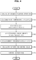
- FIG. 4 is a flowchart illustrating a method of controlling an outdoor fan during the cooling or dehumidification operation of FIG. 3 .
- the air conditioner 100 may calculate the dew point temperature by using the humidity value detected by the indoor humidity sensor 115 and the indoor set temperature (310 and 320).
- the indoor set temperature may be input by the user through the input 111 or may be preset in the air conditioner 100.
- the air conditioner 100 may calculate the temperature difference between the calculated dew point temperature and the indoor heat exchanger temperature and the change amount of the indoor heat exchanger temperature (330).
- the air conditioner 100 may calculate the frequency change amount of the compressor by using the calculated temperature difference between the dew point temperature and the indoor heat exchanger temperature and the change amount of the indoor heat exchanger temperature (340).
- the air conditioner 100 may calculate the frequency change amount of the compressor by applying the temperature difference between the dew point temperature and the indoor heat exchanger temperature and the change amount of the indoor heat exchanger temperature to the compressor fuzzy table.
- the compressor fuzzy table decreases the compressor frequency when the indoor heat exchanger temperature gradually decreases or falls below the dew point temperature, and increases the compressor frequency when the indoor heat exchanger temperature is gradually increased or exceeds the dew point temperature.
- the air conditioner 100 may calculate the current compressor frequency based on the previous compressor frequency and the frequency change amount of the compressor (350).
- the air conditioner 100 calculates a rotation speed control value of the outdoor fan (14 in FIG. 1 ) by using the current compressor frequency and the outdoor temperature, and controls the outdoor fan 14 by using the rotational speed control value of the outdoor fan 14 (360, 370).
- FIG. 5 is a flowchart illustrating a control method of an electromagnetic expansion valve in the cooling or dehumidifying operation of FIG. 3 .
- the air conditioner 100 may calculate the dew point temperature by using the humidity value detected by the indoor humidity sensor 115 and the indoor set temperature (410 and 420).
- the indoor set temperature may be input by the user through the input 111 or may be preset in the air conditioner 100.
- the air conditioner 100 may calculate the temperature difference between the calculated dew point temperature and the indoor heat exchanger temperature and the change amount of the indoor heat exchanger temperature (430).
- the air conditioner 100 may calculate the frequency change amount of the compressor by using the calculated temperature difference between the dew point temperature and the indoor heat exchanger temperature and the change amount of the indoor heat exchanger temperature (440).
- the air conditioner 100 may calculate the frequency change amount of the compressor by applying the temperature difference between the dew point temperature and the indoor heat exchanger temperature and the change amount of the indoor heat exchanger temperature to the compressor fuzzy table.
- the compressor fuzzy table decreases the compressor frequency when the indoor heat exchanger temperature gradually decreases or falls below the dew point temperature, and increases the compressor frequency when the indoor heat exchanger temperature is gradually increased or exceeds the dew point temperature.
- the air conditioner 100 may calculate the current compressor frequency based on the previous compressor frequency and the amount of change in the compressor (450).
- the air conditioner 100 calculates a control value of the electronic expansion valve (17 in FIG. 1 ) by using the current compressor frequency, room temperature, and outdoor temperature, and the electronic expansion valve may be controlled using the calculated control value of the electronic expansion valve (460, 470).
- the disclosed embodiments may be implemented in the form of a recording medium for storing instructions executable by a computer.
- the instructions may be stored in the form of a program code, and when executed by a processor, may generate a program module to perform the operations of the disclosed embodiments.
- the recording medium may be implemented as a computer-readable recording medium.
- the computer-readable recording medium includes all kinds of recording media having stored thereon instructions which can be read by a computer.
- ROM read only memory
- RAM random access memory
- magnetic tape a magnetic tape
- magnetic disk a magnetic disk
- flash memory an optical data storage device, and the like.
Landscapes
- Engineering & Computer Science (AREA)
- Mechanical Engineering (AREA)
- General Engineering & Computer Science (AREA)
- Chemical & Material Sciences (AREA)
- Combustion & Propulsion (AREA)
- Physics & Mathematics (AREA)
- Signal Processing (AREA)
- Fuzzy Systems (AREA)
- Mathematical Physics (AREA)
- Thermal Sciences (AREA)
- Air Conditioning Control Device (AREA)
Claims (13)
- Klimaanlage, die Folgendes umfasst:einen Kompressor (133);einen Innenraum-Wärmetauschertemperatursensor (113), der zum Erfassen einer Innenraum-Wärmetauschertemperatur konfiguriert ist;einen Innenraum-Feuchtigkeitssensor (115), der zum Erfassen von Innenraum-Feuchtigkeit konfiguriert ist; undeinen Regler (136), der zum Berechnen einer Taupunkttemperatur anhand eines vom Innenraum-Feuchtigkeitssensor (115) erfassten Feuchtigkeitswerts und einer Innenraum-Solltemperatur konfiguriert ist,dadurch gekennzeichnet, dassder Regler (136) einen Frequenzänderungsbetrag des Kompressors (133) auf der Basis einer Temperaturdifferenz zwischen der Taupunkttemperatur und der Innenraum-Wärmetauschertemperatur und eines Änderungsbetrags der Innenraum-Wärmetauschertemperatur berechnet, undwobei der Regler (136) eine aktuelle Kompressorfrequenz durch Reflektieren des Frequenzänderungsbetrags des Kompressors (133) auf einer vorherigen Kompressorfrequenz berechnet und eine Frequenz des Kompressors (133) auf der Basis der berechneten aktuellen Kompressorfrequenz regelt.
- Klimaanlage nach Anspruch 1, wobei der Regler einen Frequenzänderungsbetrag des Kompressors durch Anwenden der Temperaturdifferenz zwischen der Taupunkttemperatur und der Innenraum-Wärmetauschertemperatur und des Änderungsbetrags der Innenraum-Wärmetauschertemperatur auf eine Kompressor-Fuzzy-Tabelle berechnet.
- Klimaanlage nach Anspruch 2, wobei die Kompressor-Fuzzy-Tabelle zum Verringern der Kompressorfrequenz, wenn die Innenraum-Wärmetauschertemperatur allmählich abgesenkt wird oder unter die Taupunkttemperatur fällt, und zum Erhöhen der Kompressorfrequenz konfiguriert ist, wenn die Innenraum-Wärmetauschertemperatur allmählich erhöht wird oder die Taupunkttemperatur übersteigt.
- Klimaanlage nach Anspruch 1, wobei der Regler die aktuelle Kompressorfrequenz auf der Basis einer vorherigen Kompressorfrequenz und des Frequenzänderungsbetrags des Kompressors berechnet und eine Drehzahl eines Außenlüfters anhand der berechneten aktuellen Kompressorfrequenz und einer Außentemperatur regelt.
- Klimaanlage nach Anspruch 1, wobei der Regler die aktuelle Kompressorfrequenz auf der Basis einer vorherigen Kompressorfrequenz und des Frequenzänderungsbetrags des Kompressors berechnet und ein elektronisches Expansionsventil (134) anhand der berechneten aktuellen Kompressorfrequenz und der Innen- und Außentemperaturen regelt.
- Klimaanlage nach Anspruch 1, wobei der Regler so regelt, dass die Innenraum-Wärmetauschertemperatur niedriger als die Taupunkttemperatur ist.
- Verfahren zum Regeln einer Klimaanlage, wobei das Verfahren Folgendes beinhaltet:Berechnen einer Taupunkttemperatur anhand eines von einem Innenraum-Feuchtigkeitssensor (115) erfassten Feuchtigkeitswerts und einer Innenraum-Solltemperatur, wenn ein Kühl- oder Entfeuchtungsbetrieb gefahren wird;Berechnen einer Temperaturdifferenz zwischen der Taupunkttemperatur und einer Innenraum-Wärmetauschertemperatur und eines Temperaturänderungsbetrags eines Innenraum-Wärmetauschers (21) ;gekennzeichnet durch fernerBerechnen eines Frequenzänderungsbetrags eines Kompressors (133) auf der Basis der Temperaturdifferenz zwischen der Taupunkttemperatur und der Innenraum-Wärmetauschertemperatur und des Temperaturänderungsbetrags des Innenraum-Wärmetauschers (21);Berechnen einer aktuellen Kompressorfrequenz durch Reflektieren des Frequenzänderungsbetrags des Kompressors (133) auf einer vorherigen Kompressorfrequenz; undRegeln des Kompressors (133) anhand der aktuellen Kompressorfrequenz.
- Verfahren nach Anspruch 7, wobei das Berechnen des Frequenzänderungsbetrags des Kompressors das Anwenden der Temperaturdifferenz zwischen der Taupunkttemperatur und der Innenraum-Wärmetauschertemperatur und des Änderungsbetrags der Innenraum-Wärmetauschertemperatur auf eine Kompressor-Fuzzy-Tabelle beinhaltet, um den Frequenzänderungsbetrag des Kompressors zu berechnen.
- Regelverfahren nach Anspruch 8, wobei die Kompressor-Fuzzy-Tabelle zum Verringern der Kompressorfrequenz, wenn die Innenraum-Wärmetauschertemperatur allmählich abgesenkt wird oder unter die Taupunkttemperatur fällt, und zum Erhöhen der Kompressorfrequenz konfiguriert ist, wenn die Innenraum-Wärmetauschertemperatur allmählich erhöht wird oder die Taupunkttemperatur übersteigt.
- Verfahren nach Anspruch 7, das ferner Folgendes beinhaltet:
Regeln einer Drehzahl eines Außenlüfters (132) anhand der berechneten aktuellen Kompressorfrequenz und einer Außentemperatur. - Verfahren nach Anspruch 10, wobei das Berechnen des Frequenzänderungsbetrags des Kompressors das Anwenden der Temperaturdifferenz zwischen der Taupunkttemperatur und der Innenraum-Wärmetauschertemperatur und des Änderungsbetrags der Innenraum-Wärmetauschertemperatur auf eine Kompressor-Fuzzy-Tabelle umfasst, um den Frequenzänderungsbetrag des Kompressors zu berechnen.
- Verfahren nach Anspruch 7, das ferner Folgendes beinhaltet:
Regeln eines elektronischen Expansionsventils (134) anhand der berechneten aktuellen Kompressorfrequenz und der Innen- und Außentemperaturen. - Verfahren nach Anspruch 12, wobei das Berechnen des Frequenzänderungsbetrags des Kompressors das Anwenden der Temperaturdifferenz zwischen der Taupunkttemperatur und der Innenraum-Wärmetauschertemperatur und des Änderungsbetrags der Innenraum-Wärmetauschertemperatur auf eine Kompressor-Fuzzy-Tabelle beinhaltet, um den Frequenzänderungsbetrag des Kompressors zu berechnen.
Applications Claiming Priority (2)
| Application Number | Priority Date | Filing Date | Title |
|---|---|---|---|
| KR1020170082756A KR20190002790A (ko) | 2017-06-29 | 2017-06-29 | 공기 조화기 및 그 제어방법 |
| PCT/KR2018/004429 WO2019004578A1 (ko) | 2017-06-29 | 2018-04-17 | 공기 조화기 및 그 제어방법 |
Publications (3)
| Publication Number | Publication Date |
|---|---|
| EP3633283A1 EP3633283A1 (de) | 2020-04-08 |
| EP3633283A4 EP3633283A4 (de) | 2020-05-06 |
| EP3633283B1 true EP3633283B1 (de) | 2021-08-18 |
Family
ID=64742440
Family Applications (1)
| Application Number | Title | Priority Date | Filing Date |
|---|---|---|---|
| EP18824350.5A Active EP3633283B1 (de) | 2017-06-29 | 2018-04-17 | Klimaanlage und steuerungsverfahren dafür |
Country Status (4)
| Country | Link |
|---|---|
| US (1) | US11655991B2 (de) |
| EP (1) | EP3633283B1 (de) |
| KR (1) | KR20190002790A (de) |
| WO (1) | WO2019004578A1 (de) |
Families Citing this family (25)
| Publication number | Priority date | Publication date | Assignee | Title |
|---|---|---|---|---|
| US11193677B2 (en) * | 2015-07-21 | 2021-12-07 | Samsung Electronics Co., Ltd. | Air conditioner and control method thereof |
| CN110094856A (zh) * | 2019-04-15 | 2019-08-06 | 青岛海尔空调电子有限公司 | 空调器及其送风控制方法 |
| KR102809591B1 (ko) * | 2019-10-25 | 2025-05-20 | 삼성전자주식회사 | 공기조화기 및 그 제어방법 |
| CN110805990B (zh) * | 2019-11-21 | 2021-01-12 | 重庆大学 | 空调器及其防凝露控制方法、装置及计算机可读存储介质 |
| CN111520865A (zh) * | 2020-05-12 | 2020-08-11 | 宁波奥克斯电气股份有限公司 | 空调控制方法、装置及空调器 |
| CN111623467B (zh) * | 2020-05-12 | 2021-11-02 | 海信(广东)空调有限公司 | 一种空调器控制方法及空调器 |
| JP7462937B2 (ja) * | 2020-06-16 | 2024-04-08 | 伸和コントロールズ株式会社 | 流量制御装置及び方法、並びにチラー |
| KR102775671B1 (ko) * | 2020-08-24 | 2025-03-06 | 삼성전자주식회사 | 신발 관리기 및 그 제어 방법 |
| CN114253335A (zh) * | 2020-09-21 | 2022-03-29 | 英飞凌科技奥地利有限公司 | 控制电路、信号转换电路和控制方法 |
| CN112128922B (zh) * | 2020-09-23 | 2021-12-24 | 创新奇智(青岛)科技有限公司 | 多联机空调系统的温控方法及装置 |
| CN114151941B (zh) * | 2021-04-19 | 2023-04-21 | 海信空调有限公司 | 控制空调器湿度调节的方法、计算机存储介质和空调器 |
| CN113108439B (zh) * | 2021-05-20 | 2021-10-08 | 广东美的制冷设备有限公司 | 空调器的控制方法、装置、空调器及存储介质 |
| CN115523628A (zh) * | 2021-06-25 | 2022-12-27 | 美的集团股份有限公司 | 空气湿度控制方法、装置、存储介质及空调器 |
| CN117836569A (zh) * | 2021-08-17 | 2024-04-05 | 三菱电机株式会社 | 空调装置 |
| KR20230108925A (ko) * | 2022-01-12 | 2023-07-19 | 삼성전자주식회사 | 공기 조화기 및 그 제어 방법 |
| CN114777293B (zh) * | 2022-03-21 | 2024-05-24 | 青岛海尔空调器有限总公司 | 用于控制变频除湿机的方法及装置、电子设备、存储介质 |
| CN115183509B (zh) * | 2022-07-18 | 2023-05-16 | 四川虹美智能科技有限公司 | 变频压缩机的转速控制方法及装置、设备、介质 |
| CN115404283A (zh) * | 2022-07-22 | 2022-11-29 | 青岛海尔特种电冰柜有限公司 | 熟成柜的控湿方法 |
| CN117537437A (zh) * | 2022-08-01 | 2024-02-09 | 青岛海尔空调器有限总公司 | 用于空调除湿的控制方法及装置、空调 |
| KR20240032579A (ko) * | 2022-09-02 | 2024-03-12 | 삼성전자주식회사 | 공기 조화기 및 그 제어 방법 |
| KR102866080B1 (ko) * | 2022-09-23 | 2025-09-30 | 엘지전자 주식회사 | 공기조화기 |
| KR102817030B1 (ko) * | 2022-09-23 | 2025-06-05 | 엘지전자 주식회사 | 공기조화기 |
| KR102817029B1 (ko) * | 2022-09-23 | 2025-06-05 | 엘지전자 주식회사 | 공기조화기 |
| KR20240051745A (ko) * | 2022-10-13 | 2024-04-22 | 삼성전자주식회사 | 공기 조화기 및 그 제어 방법 |
| US12435900B2 (en) * | 2023-10-11 | 2025-10-07 | Haier Us Appliance Solutions, Inc. | Control of discharge dewpoint for packaged terminal air conditioner |
Family Cites Families (13)
| Publication number | Priority date | Publication date | Assignee | Title |
|---|---|---|---|---|
| US4107939A (en) * | 1977-04-01 | 1978-08-22 | Carrier Corporation | Apparatus for reducing exterior condensation in an air conditioner |
| JP3190139B2 (ja) | 1992-10-13 | 2001-07-23 | 東芝キヤリア株式会社 | 空気調和機 |
| JP2848292B2 (ja) | 1995-11-10 | 1999-01-20 | ダイキン工業株式会社 | 空気調和機 |
| JPH11218350A (ja) | 1998-02-03 | 1999-08-10 | Toshiba Corp | 空気調和機 |
| JP2002286275A (ja) | 2001-03-28 | 2002-10-03 | Sanyo Electric Co Ltd | 空気調和装置のドライ運転制御方法及び空気調和装置 |
| JP3754343B2 (ja) | 2001-10-30 | 2006-03-08 | 三洋電機株式会社 | 空気調和装置 |
| KR100512278B1 (ko) | 2002-09-10 | 2005-09-02 | 엘지전자 주식회사 | 냉난방기의 제습 절전 운전방법 |
| KR100785979B1 (ko) * | 2006-08-04 | 2007-12-14 | 주식회사 대우일렉트로닉스 | 공기 조화기의 전자 팽창 밸브 제어 방법 |
| CN101925784B (zh) * | 2008-03-21 | 2014-11-26 | 三菱电机株式会社 | 室内单元以及具备该室内单元的空气调节装置 |
| KR101987788B1 (ko) | 2012-10-04 | 2019-09-26 | 웅진코웨이 주식회사 | 제습 장치 |
| US20140345307A1 (en) * | 2013-05-23 | 2014-11-27 | Air To Water Technologies, Inc. | Energy efficient dehumidifying refrigeration system |
| JP5975937B2 (ja) | 2013-06-13 | 2016-08-23 | 三菱電機株式会社 | 空気調和機 |
| KR102010375B1 (ko) | 2013-11-29 | 2019-08-16 | 웅진코웨이 주식회사 | 제습장치 및 제습장치의 동작제어방법 |
-
2017
- 2017-06-29 KR KR1020170082756A patent/KR20190002790A/ko not_active Ceased
-
2018
- 2018-04-17 EP EP18824350.5A patent/EP3633283B1/de active Active
- 2018-04-17 WO PCT/KR2018/004429 patent/WO2019004578A1/ko not_active Ceased
- 2018-04-17 US US16/627,250 patent/US11655991B2/en active Active
Also Published As
| Publication number | Publication date |
|---|---|
| EP3633283A1 (de) | 2020-04-08 |
| EP3633283A4 (de) | 2020-05-06 |
| WO2019004578A1 (ko) | 2019-01-03 |
| KR20190002790A (ko) | 2019-01-09 |
| US11655991B2 (en) | 2023-05-23 |
| US20200132319A1 (en) | 2020-04-30 |
Similar Documents
| Publication | Publication Date | Title |
|---|---|---|
| US11655991B2 (en) | Air conditioner and method of controlling air conditioner | |
| EP3255352B1 (de) | Verfahren und system zur optimierung der geschwindigkeit von mindestens einem von einem verdichter mit variabler geschwindigkeit und einem umwalzgebläse mit variabler geschwindigkeit zur verbesserung der latenten kapazität | |
| JP5627620B2 (ja) | 空気調和機 | |
| US10655877B2 (en) | Evaporator coil protection for HVAC systems | |
| US10337755B2 (en) | Method and apparatus for reheat dehumidification with variable air volume | |
| EP3203166B1 (de) | Klimaanlage und verfahren zur steuerung davon | |
| US10371407B2 (en) | Air conditioning apparatus | |
| US9726408B2 (en) | Air conditioner | |
| EP3810996B1 (de) | Klimaanlage und steuerungsverfahren dafür | |
| EP3054229B1 (de) | Klimaanlage | |
| KR20140090323A (ko) | 공기조화기 및 그 제어 방법 | |
| KR20150125343A (ko) | 공기조화기 및 그 제어방법 | |
| KR102243828B1 (ko) | 공기조화기의 제어 방법 | |
| US10852031B2 (en) | Air conditioner and method for controlling the same | |
| EP3255353B1 (de) | Verfahren und vorrichtung zur optimierung der latenten leistung eines verdichtersystems mit variabler drehzahl | |
| JP6785867B2 (ja) | 空調システム | |
| CN115406072B (zh) | 多联机空调系统的控制方法及相关产品 | |
| KR20090041604A (ko) | 공기조화기 | |
| US10077929B2 (en) | Movement of electronic expansion valve | |
| JP6615371B2 (ja) | 冷凍サイクル装置 | |
| KR102035465B1 (ko) | 공기 조화기, 공기 조화기의 실내기, 및 실내기의 운전 모드 판단 방법 | |
| JP2016044833A (ja) | 熱媒体循環システム | |
| JP7635282B2 (ja) | 空気調和装置 | |
| WO2015045293A1 (ja) | 空気調和システム | |
| JPH04257644A (ja) | 空気調和機の制御方法 |
Legal Events
| Date | Code | Title | Description |
|---|---|---|---|
| STAA | Information on the status of an ep patent application or granted ep patent |
Free format text: STATUS: THE INTERNATIONAL PUBLICATION HAS BEEN MADE |
|
| PUAI | Public reference made under article 153(3) epc to a published international application that has entered the european phase |
Free format text: ORIGINAL CODE: 0009012 |
|
| STAA | Information on the status of an ep patent application or granted ep patent |
Free format text: STATUS: REQUEST FOR EXAMINATION WAS MADE |
|
| 17P | Request for examination filed |
Effective date: 20200103 |
|
| AK | Designated contracting states |
Kind code of ref document: A1 Designated state(s): AL AT BE BG CH CY CZ DE DK EE ES FI FR GB GR HR HU IE IS IT LI LT LU LV MC MK MT NL NO PL PT RO RS SE SI SK SM TR |
|
| AX | Request for extension of the european patent |
Extension state: BA ME |
|
| A4 | Supplementary search report drawn up and despatched |
Effective date: 20200403 |
|
| RIC1 | Information provided on ipc code assigned before grant |
Ipc: F24F 110/12 20180101ALI20200330BHEP Ipc: F24F 11/83 20180101AFI20200330BHEP Ipc: F24F 11/63 20180101ALI20200330BHEP Ipc: F24F 110/20 20180101ALI20200330BHEP Ipc: F24F 11/30 20180101ALI20200330BHEP Ipc: F24F 110/10 20180101ALI20200330BHEP Ipc: F25B 49/02 20060101ALI20200330BHEP Ipc: F24F 11/00 20180101ALI20200330BHEP |
|
| DAV | Request for validation of the european patent (deleted) | ||
| DAX | Request for extension of the european patent (deleted) | ||
| GRAP | Despatch of communication of intention to grant a patent |
Free format text: ORIGINAL CODE: EPIDOSNIGR1 |
|
| STAA | Information on the status of an ep patent application or granted ep patent |
Free format text: STATUS: GRANT OF PATENT IS INTENDED |
|
| RIC1 | Information provided on ipc code assigned before grant |
Ipc: F24F 110/10 20180101ALI20201214BHEP Ipc: F24F 110/12 20180101ALI20201214BHEP Ipc: F24F 11/83 20180101AFI20201214BHEP Ipc: F24F 11/63 20180101ALI20201214BHEP Ipc: F24F 110/20 20180101ALI20201214BHEP Ipc: F24F 11/00 20180101ALI20201214BHEP Ipc: F24F 11/30 20180101ALI20201214BHEP Ipc: F25B 49/02 20060101ALI20201214BHEP |
|
| INTG | Intention to grant announced |
Effective date: 20210113 |
|
| GRAJ | Information related to disapproval of communication of intention to grant by the applicant or resumption of examination proceedings by the epo deleted |
Free format text: ORIGINAL CODE: EPIDOSDIGR1 |
|
| STAA | Information on the status of an ep patent application or granted ep patent |
Free format text: STATUS: REQUEST FOR EXAMINATION WAS MADE |
|
| GRAS | Grant fee paid |
Free format text: ORIGINAL CODE: EPIDOSNIGR3 |
|
| STAA | Information on the status of an ep patent application or granted ep patent |
Free format text: STATUS: GRANT OF PATENT IS INTENDED |
|
| INTC | Intention to grant announced (deleted) | ||
| GRAP | Despatch of communication of intention to grant a patent |
Free format text: ORIGINAL CODE: EPIDOSNIGR1 |
|
| GRAA | (expected) grant |
Free format text: ORIGINAL CODE: 0009210 |
|
| STAA | Information on the status of an ep patent application or granted ep patent |
Free format text: STATUS: THE PATENT HAS BEEN GRANTED |
|
| INTG | Intention to grant announced |
Effective date: 20210629 |
|
| AK | Designated contracting states |
Kind code of ref document: B1 Designated state(s): AL AT BE BG CH CY CZ DE DK EE ES FI FR GB GR HR HU IE IS IT LI LT LU LV MC MK MT NL NO PL PT RO RS SE SI SK SM TR |
|
| REG | Reference to a national code |
Ref country code: GB Ref legal event code: FG4D |
|
| REG | Reference to a national code |
Ref country code: CH Ref legal event code: EP |
|
| REG | Reference to a national code |
Ref country code: DE Ref legal event code: R096 Ref document number: 602018022170 Country of ref document: DE |
|
| REG | Reference to a national code |
Ref country code: IE Ref legal event code: FG4D Ref country code: AT Ref legal event code: REF Ref document number: 1421975 Country of ref document: AT Kind code of ref document: T Effective date: 20210915 |
|
| REG | Reference to a national code |
Ref country code: LT Ref legal event code: MG9D |
|
| REG | Reference to a national code |
Ref country code: NL Ref legal event code: MP Effective date: 20210818 |
|
| REG | Reference to a national code |
Ref country code: AT Ref legal event code: MK05 Ref document number: 1421975 Country of ref document: AT Kind code of ref document: T Effective date: 20210818 |
|
| PG25 | Lapsed in a contracting state [announced via postgrant information from national office to epo] |
Ref country code: HR Free format text: LAPSE BECAUSE OF FAILURE TO SUBMIT A TRANSLATION OF THE DESCRIPTION OR TO PAY THE FEE WITHIN THE PRESCRIBED TIME-LIMIT Effective date: 20210818 Ref country code: PT Free format text: LAPSE BECAUSE OF FAILURE TO SUBMIT A TRANSLATION OF THE DESCRIPTION OR TO PAY THE FEE WITHIN THE PRESCRIBED TIME-LIMIT Effective date: 20211220 Ref country code: NO Free format text: LAPSE BECAUSE OF FAILURE TO SUBMIT A TRANSLATION OF THE DESCRIPTION OR TO PAY THE FEE WITHIN THE PRESCRIBED TIME-LIMIT Effective date: 20211118 Ref country code: BG Free format text: LAPSE BECAUSE OF FAILURE TO SUBMIT A TRANSLATION OF THE DESCRIPTION OR TO PAY THE FEE WITHIN THE PRESCRIBED TIME-LIMIT Effective date: 20211118 Ref country code: AT Free format text: LAPSE BECAUSE OF FAILURE TO SUBMIT A TRANSLATION OF THE DESCRIPTION OR TO PAY THE FEE WITHIN THE PRESCRIBED TIME-LIMIT Effective date: 20210818 Ref country code: LT Free format text: LAPSE BECAUSE OF FAILURE TO SUBMIT A TRANSLATION OF THE DESCRIPTION OR TO PAY THE FEE WITHIN THE PRESCRIBED TIME-LIMIT Effective date: 20210818 Ref country code: SE Free format text: LAPSE BECAUSE OF FAILURE TO SUBMIT A TRANSLATION OF THE DESCRIPTION OR TO PAY THE FEE WITHIN THE PRESCRIBED TIME-LIMIT Effective date: 20210818 Ref country code: RS Free format text: LAPSE BECAUSE OF FAILURE TO SUBMIT A TRANSLATION OF THE DESCRIPTION OR TO PAY THE FEE WITHIN THE PRESCRIBED TIME-LIMIT Effective date: 20210818 Ref country code: ES Free format text: LAPSE BECAUSE OF FAILURE TO SUBMIT A TRANSLATION OF THE DESCRIPTION OR TO PAY THE FEE WITHIN THE PRESCRIBED TIME-LIMIT Effective date: 20210818 Ref country code: FI Free format text: LAPSE BECAUSE OF FAILURE TO SUBMIT A TRANSLATION OF THE DESCRIPTION OR TO PAY THE FEE WITHIN THE PRESCRIBED TIME-LIMIT Effective date: 20210818 |
|
| PG25 | Lapsed in a contracting state [announced via postgrant information from national office to epo] |
Ref country code: PL Free format text: LAPSE BECAUSE OF FAILURE TO SUBMIT A TRANSLATION OF THE DESCRIPTION OR TO PAY THE FEE WITHIN THE PRESCRIBED TIME-LIMIT Effective date: 20210818 Ref country code: LV Free format text: LAPSE BECAUSE OF FAILURE TO SUBMIT A TRANSLATION OF THE DESCRIPTION OR TO PAY THE FEE WITHIN THE PRESCRIBED TIME-LIMIT Effective date: 20210818 Ref country code: GR Free format text: LAPSE BECAUSE OF FAILURE TO SUBMIT A TRANSLATION OF THE DESCRIPTION OR TO PAY THE FEE WITHIN THE PRESCRIBED TIME-LIMIT Effective date: 20211119 |
|
| PG25 | Lapsed in a contracting state [announced via postgrant information from national office to epo] |
Ref country code: NL Free format text: LAPSE BECAUSE OF FAILURE TO SUBMIT A TRANSLATION OF THE DESCRIPTION OR TO PAY THE FEE WITHIN THE PRESCRIBED TIME-LIMIT Effective date: 20210818 |
|
| PG25 | Lapsed in a contracting state [announced via postgrant information from national office to epo] |
Ref country code: DK Free format text: LAPSE BECAUSE OF FAILURE TO SUBMIT A TRANSLATION OF THE DESCRIPTION OR TO PAY THE FEE WITHIN THE PRESCRIBED TIME-LIMIT Effective date: 20210818 |
|
| REG | Reference to a national code |
Ref country code: DE Ref legal event code: R097 Ref document number: 602018022170 Country of ref document: DE |
|
| PG25 | Lapsed in a contracting state [announced via postgrant information from national office to epo] |
Ref country code: SM Free format text: LAPSE BECAUSE OF FAILURE TO SUBMIT A TRANSLATION OF THE DESCRIPTION OR TO PAY THE FEE WITHIN THE PRESCRIBED TIME-LIMIT Effective date: 20210818 Ref country code: SK Free format text: LAPSE BECAUSE OF FAILURE TO SUBMIT A TRANSLATION OF THE DESCRIPTION OR TO PAY THE FEE WITHIN THE PRESCRIBED TIME-LIMIT Effective date: 20210818 Ref country code: RO Free format text: LAPSE BECAUSE OF FAILURE TO SUBMIT A TRANSLATION OF THE DESCRIPTION OR TO PAY THE FEE WITHIN THE PRESCRIBED TIME-LIMIT Effective date: 20210818 Ref country code: EE Free format text: LAPSE BECAUSE OF FAILURE TO SUBMIT A TRANSLATION OF THE DESCRIPTION OR TO PAY THE FEE WITHIN THE PRESCRIBED TIME-LIMIT Effective date: 20210818 Ref country code: CZ Free format text: LAPSE BECAUSE OF FAILURE TO SUBMIT A TRANSLATION OF THE DESCRIPTION OR TO PAY THE FEE WITHIN THE PRESCRIBED TIME-LIMIT Effective date: 20210818 Ref country code: AL Free format text: LAPSE BECAUSE OF FAILURE TO SUBMIT A TRANSLATION OF THE DESCRIPTION OR TO PAY THE FEE WITHIN THE PRESCRIBED TIME-LIMIT Effective date: 20210818 |
|
| PLBE | No opposition filed within time limit |
Free format text: ORIGINAL CODE: 0009261 |
|
| STAA | Information on the status of an ep patent application or granted ep patent |
Free format text: STATUS: NO OPPOSITION FILED WITHIN TIME LIMIT |
|
| 26N | No opposition filed |
Effective date: 20220519 |
|
| PG25 | Lapsed in a contracting state [announced via postgrant information from national office to epo] |
Ref country code: SI Free format text: LAPSE BECAUSE OF FAILURE TO SUBMIT A TRANSLATION OF THE DESCRIPTION OR TO PAY THE FEE WITHIN THE PRESCRIBED TIME-LIMIT Effective date: 20210818 |
|
| REG | Reference to a national code |
Ref country code: DE Ref legal event code: R119 Ref document number: 602018022170 Country of ref document: DE |
|
| REG | Reference to a national code |
Ref country code: CH Ref legal event code: PL |
|
| REG | Reference to a national code |
Ref country code: BE Ref legal event code: MM Effective date: 20220430 |
|
| PG25 | Lapsed in a contracting state [announced via postgrant information from national office to epo] |
Ref country code: MC Free format text: LAPSE BECAUSE OF FAILURE TO SUBMIT A TRANSLATION OF THE DESCRIPTION OR TO PAY THE FEE WITHIN THE PRESCRIBED TIME-LIMIT Effective date: 20210818 Ref country code: LI Free format text: LAPSE BECAUSE OF NON-PAYMENT OF DUE FEES Effective date: 20220430 Ref country code: FR Free format text: LAPSE BECAUSE OF NON-PAYMENT OF DUE FEES Effective date: 20220430 Ref country code: DE Free format text: LAPSE BECAUSE OF NON-PAYMENT OF DUE FEES Effective date: 20221103 Ref country code: CH Free format text: LAPSE BECAUSE OF NON-PAYMENT OF DUE FEES Effective date: 20220430 Ref country code: LU Free format text: LAPSE BECAUSE OF NON-PAYMENT OF DUE FEES Effective date: 20220417 |
|
| PG25 | Lapsed in a contracting state [announced via postgrant information from national office to epo] |
Ref country code: BE Free format text: LAPSE BECAUSE OF NON-PAYMENT OF DUE FEES Effective date: 20220430 |
|
| PG25 | Lapsed in a contracting state [announced via postgrant information from national office to epo] |
Ref country code: IE Free format text: LAPSE BECAUSE OF NON-PAYMENT OF DUE FEES Effective date: 20220417 |
|
| PG25 | Lapsed in a contracting state [announced via postgrant information from national office to epo] |
Ref country code: MK Free format text: LAPSE BECAUSE OF FAILURE TO SUBMIT A TRANSLATION OF THE DESCRIPTION OR TO PAY THE FEE WITHIN THE PRESCRIBED TIME-LIMIT Effective date: 20210818 Ref country code: CY Free format text: LAPSE BECAUSE OF FAILURE TO SUBMIT A TRANSLATION OF THE DESCRIPTION OR TO PAY THE FEE WITHIN THE PRESCRIBED TIME-LIMIT Effective date: 20210818 |
|
| PG25 | Lapsed in a contracting state [announced via postgrant information from national office to epo] |
Ref country code: HU Free format text: LAPSE BECAUSE OF FAILURE TO SUBMIT A TRANSLATION OF THE DESCRIPTION OR TO PAY THE FEE WITHIN THE PRESCRIBED TIME-LIMIT; INVALID AB INITIO Effective date: 20180417 |
|
| PG25 | Lapsed in a contracting state [announced via postgrant information from national office to epo] |
Ref country code: TR Free format text: LAPSE BECAUSE OF FAILURE TO SUBMIT A TRANSLATION OF THE DESCRIPTION OR TO PAY THE FEE WITHIN THE PRESCRIBED TIME-LIMIT Effective date: 20210818 |
|
| PG25 | Lapsed in a contracting state [announced via postgrant information from national office to epo] |
Ref country code: MT Free format text: LAPSE BECAUSE OF FAILURE TO SUBMIT A TRANSLATION OF THE DESCRIPTION OR TO PAY THE FEE WITHIN THE PRESCRIBED TIME-LIMIT Effective date: 20210818 |
|
| PGFP | Annual fee paid to national office [announced via postgrant information from national office to epo] |
Ref country code: IT Payment date: 20250321 Year of fee payment: 8 |
|
| PGFP | Annual fee paid to national office [announced via postgrant information from national office to epo] |
Ref country code: GB Payment date: 20260324 Year of fee payment: 9 |