EP3631975B1 - Elektrische schaltung und verwendung der elektrischen schaltung - Google Patents
Elektrische schaltung und verwendung der elektrischen schaltung Download PDFInfo
- Publication number
- EP3631975B1 EP3631975B1 EP18729337.8A EP18729337A EP3631975B1 EP 3631975 B1 EP3631975 B1 EP 3631975B1 EP 18729337 A EP18729337 A EP 18729337A EP 3631975 B1 EP3631975 B1 EP 3631975B1
- Authority
- EP
- European Patent Office
- Prior art keywords
- energy
- electrical circuit
- energy store
- solid
- circuit according
- Prior art date
- Legal status (The legal status is an assumption and is not a legal conclusion. Google has not performed a legal analysis and makes no representation as to the accuracy of the status listed.)
- Active
Links
Images


Classifications
-
- H—ELECTRICITY
- H02—GENERATION; CONVERSION OR DISTRIBUTION OF ELECTRIC POWER
- H02J—ELECTRIC POWER NETWORKS; CIRCUIT ARRANGEMENTS OR SYSTEMS FOR SUPPLYING OR DISTRIBUTING ELECTRIC POWER; SYSTEMS FOR STORING ELECTRIC ENERGY
- H02J7/00—Circuit arrangements for charging or discharging batteries or for supplying loads from batteries
- H02J7/34—Parallel operation in networks using both storage and other DC sources, e.g. providing buffering
- H02J7/35—Parallel operation in networks using both storage and other DC sources, e.g. providing buffering with light sensitive cells
-
- H—ELECTRICITY
- H02—GENERATION; CONVERSION OR DISTRIBUTION OF ELECTRIC POWER
- H02S—GENERATION OF ELECTRIC POWER BY CONVERSION OF INFRARED RADIATION, VISIBLE LIGHT OR ULTRAVIOLET LIGHT, e.g. USING PHOTOVOLTAIC [PV] MODULES
- H02S40/00—Components or accessories in combination with PV modules, not provided for in groups H02S10/00 - H02S30/00
- H02S40/30—Electrical components
- H02S40/38—Energy storage means, e.g. batteries, structurally associated with PV modules
-
- H—ELECTRICITY
- H01—ELECTRIC ELEMENTS
- H01M—PROCESSES OR MEANS, e.g. BATTERIES, FOR THE DIRECT CONVERSION OF CHEMICAL ENERGY INTO ELECTRICAL ENERGY
- H01M10/00—Secondary cells; Manufacture thereof
- H01M10/42—Methods or arrangements for servicing or maintenance of secondary cells or secondary half-cells
- H01M10/46—Accumulators structurally combined with charging apparatus
- H01M10/465—Accumulators structurally combined with charging apparatus with solar battery as charging system
-
- H—ELECTRICITY
- H02—GENERATION; CONVERSION OR DISTRIBUTION OF ELECTRIC POWER
- H02J—ELECTRIC POWER NETWORKS; CIRCUIT ARRANGEMENTS OR SYSTEMS FOR SUPPLYING OR DISTRIBUTING ELECTRIC POWER; SYSTEMS FOR STORING ELECTRIC ENERGY
- H02J7/00—Circuit arrangements for charging or discharging batteries or for supplying loads from batteries
- H02J7/34—Parallel operation in networks using both storage and other DC sources, e.g. providing buffering
- H02J7/345—Parallel operation in networks using both storage and other DC sources, e.g. providing buffering using capacitors as storage or buffering devices
-
- H—ELECTRICITY
- H10—SEMICONDUCTOR DEVICES; ELECTRIC SOLID-STATE DEVICES NOT OTHERWISE PROVIDED FOR
- H10F—INORGANIC SEMICONDUCTOR DEVICES SENSITIVE TO INFRARED RADIATION, LIGHT, ELECTROMAGNETIC RADIATION OF SHORTER WAVELENGTH OR CORPUSCULAR RADIATION
- H10F77/00—Constructional details of devices covered by this subclass
- H10F77/90—Energy storage means directly associated or integrated with photovoltaic cells, e.g. capacitors integrated with photovoltaic cells
-
- Y—GENERAL TAGGING OF NEW TECHNOLOGICAL DEVELOPMENTS; GENERAL TAGGING OF CROSS-SECTIONAL TECHNOLOGIES SPANNING OVER SEVERAL SECTIONS OF THE IPC; TECHNICAL SUBJECTS COVERED BY FORMER USPC CROSS-REFERENCE ART COLLECTIONS [XRACs] AND DIGESTS
- Y02—TECHNOLOGIES OR APPLICATIONS FOR MITIGATION OR ADAPTATION AGAINST CLIMATE CHANGE
- Y02E—REDUCTION OF GREENHOUSE GAS [GHG] EMISSIONS, RELATED TO ENERGY GENERATION, TRANSMISSION OR DISTRIBUTION
- Y02E10/00—Energy generation through renewable energy sources
- Y02E10/50—Photovoltaic [PV] energy
-
- Y—GENERAL TAGGING OF NEW TECHNOLOGICAL DEVELOPMENTS; GENERAL TAGGING OF CROSS-SECTIONAL TECHNOLOGIES SPANNING OVER SEVERAL SECTIONS OF THE IPC; TECHNICAL SUBJECTS COVERED BY FORMER USPC CROSS-REFERENCE ART COLLECTIONS [XRACs] AND DIGESTS
- Y02—TECHNOLOGIES OR APPLICATIONS FOR MITIGATION OR ADAPTATION AGAINST CLIMATE CHANGE
- Y02E—REDUCTION OF GREENHOUSE GAS [GHG] EMISSIONS, RELATED TO ENERGY GENERATION, TRANSMISSION OR DISTRIBUTION
- Y02E60/00—Enabling technologies; Technologies with a potential or indirect contribution to GHG emissions mitigation
- Y02E60/10—Energy storage using batteries
-
- Y—GENERAL TAGGING OF NEW TECHNOLOGICAL DEVELOPMENTS; GENERAL TAGGING OF CROSS-SECTIONAL TECHNOLOGIES SPANNING OVER SEVERAL SECTIONS OF THE IPC; TECHNICAL SUBJECTS COVERED BY FORMER USPC CROSS-REFERENCE ART COLLECTIONS [XRACs] AND DIGESTS
- Y02—TECHNOLOGIES OR APPLICATIONS FOR MITIGATION OR ADAPTATION AGAINST CLIMATE CHANGE
- Y02E—REDUCTION OF GREENHOUSE GAS [GHG] EMISSIONS, RELATED TO ENERGY GENERATION, TRANSMISSION OR DISTRIBUTION
- Y02E70/00—Other energy conversion or management systems reducing GHG emissions
- Y02E70/30—Systems combining energy storage with energy generation of non-fossil origin
Definitions
- the invention relates to electrical circuits, e.g. B. for electrical systems that require a self-sufficient energy supply, and the use of such a circuit.
- a light switch with a radio module can be used, the radio module being supplied with electrical energy by a conventional battery.
- the electrical circuit has an energy converter, an energy store, a first connection and a second connection.
- the energy converter is electrically coupled to the first and to the second connection.
- the energy store is also electrically coupled to the first and second connection.
- the energy converter is suitable and intended to charge the energy store in discrete time segments.
- the energy store is suitable and intended to continuously provide energy.
- the energy converter comprises at least one solar cell.
- the energy store comprises at least one solid-state accumulator.
- the first and the second connection are essentially the two connections via which the electrical circuit supplies electrical energy to other circuit components can emit an external circuit environment.
- the energy converter with the solar cell is intended to convert electromagnetic energy, preferably in the visible spectrum, into electrical energy.
- the energy storage device with its solid-state accumulator is intended to be used by the energy converter at certain time intervals, e.g. B. when light falls on the solar cell, receive and store between them. That means that even then electrical energy is on the two connections is made available (continuously) when no light falls on the solar cell.
- the electrical circuit has an energy source that provides energy even in the dark.
- the solid-state accumulator of the energy store is a type of accumulator in which its electrodes and the electrolyte between the electrodes consist of a non-liquid material.
- Such a solid state storage battery can be made small in size and in a variety of different physical shapes.
- the advantage for the user is that batteries do not have to be replaced regularly. At the same time, there is no additional space requirement and the costs are not increased or even reduced compared to solutions with magnetic or piezoelectric harvesters.
- a familiar switching feeling when pressing a switch e.g. B. a light switch can be retained.
- a solid-state accumulator eliminates the risk of electrolyte leaking, which in conventional accumulators often has corrosive properties. In addition, the risk of self-ignition of the solid-state accumulator is reduced.
- the accumulator can be realized in practically any shape. The mechanical resistance is better than that of conventional, classic batteries or accumulators, at least if the accumulator is to have particularly small dimensions and, for this purpose, is designed without a stabilizing outer shell.
- the usual materials that are used in solid-state accumulators can be used as materials for the electrodes or for the electrolyte.
- the energy converter when incident light, load the energy storage.
- both the energy converter and the energy store can together deliver energy to other circuit components if energy is used and light falls on the solar cell of the energy converter at the same time.
- the electrical circuit also includes a diode.
- the diode can be connected between the energy store and the energy converter. It is possible for the diode to be connected in series between an electrode of the energy store and an electrode of the energy converter.
- the diode is used to prevent the energy storage device from self-discharging via the energy converter, e.g. B. to protect in the dark and a finite conductivity of the energy converter in the dark.
- the diode is preferably connected in such a way that its own resistance is as low as possible while the energy converter charges the energy store. The diode is then switched in the reverse direction for the opposite current direction.
- the electrical circuit also has a varistor.
- the varistor is connected in parallel to the energy store and parallel to the energy converter.
- the varistor is a component with a voltage-dependent resistor. The electrical resistance of the varistor decreases as the applied voltage increases.
- the varistor With a low applied voltage, the varistor preferably has a very high electrical resistance. At higher voltages, the varistor preferably has a very low electrical resistance.
- the energy storage device can be protected from overload when, for example, the energy converter, e.g. B. in strong light and filled energy storage, or other circuit components provide an excess of energy.
- the energy converter e.g. B. in strong light and filled energy storage, or other circuit components provide an excess of energy.
- the varistor thus serves as overvoltage protection, especially for the solar cells.
- the electrical circuit can additionally comprise a resistive element.
- the resistive element can be connected in series with the solid-state accumulator in the energy store.
- the resistive element e.g. B. an ohmic resistor
- the resistive element can thus represent a series resistor that prevents an excessive charging current.
- the electrical circuit may additionally include a capacitive element in the energy store.
- the capacitive element can be connected in parallel to the solid-state accumulator.
- the capacitive element e.g. B. a capacitor
- the capacitive element can represent a backup capacitor that the solid state accumulator when providing electrical energy with a relatively high electrical power, z. B. for a single switching operation is available.
- Solid-state accumulators have a comparatively high internal resistance, which is compensated for by the capacitor.
- the energy converter comprises three or six solar cells.
- the solar cells can be connected in series.
- the energy store can comprise one or two solid-state accumulators which are connected in series.
- a single solar cell can provide a voltage of around 0.5 V if it receives a corresponding amount of light.
- a solid state storage battery can provide a typical supply voltage of around 1.5 V when it is charged.
- a solid-state accumulator with a supply voltage of around 1.5 V can replace conventional batteries with a supply voltage of 1.5 V.
- Three solar cells which are connected in series and can each provide a single supply voltage of 0.5 V, can together provide a supply voltage of around 1.5 V and are therefore well suited to charging the solid-state battery with a supply voltage of 1.5 V.
- Six solar cells connected in series can charge a series connection of two accumulators.
- Two batteries connected in series can provide a supply voltage of 3 V.
- Such an electrical connection can represent a replacement for a voltage supply with two series-connected batteries.
- the electrical circuit can also include three, four, five, six, seven, eight, nine or ten solid-state accumulators and accordingly nine, twelve, fifteen, eighteen, 21, 24, 27 or thirty solar cells in energy storage.
- solid-state accumulator it is possible for the solid-state accumulator to be implemented as a reflow-solderable SMD component. In the case of conventional batteries or accumulators, this can otherwise not be achieved or only with a disproportionately high technical effort and corresponding costs.
- Reflow soldering is a soft soldering process for soldering SMD components.
- Solid-state accumulators are well suited for reflow soldering, since their components can withstand the temperatures occurring during reflow soldering, at least for the relatively short time of soldering, without the solid-state accumulator being damaged. That The same also applies to the other circuit components of the electrical circuit.
- SMD Surface-Mounted Device
- At least one circuit component is embedded in a ceramic multilayer substrate.
- a ceramic multilayer substrate has on the one hand a ceramic layer and a metallization layer.
- Passive circuit elements e.g. B. resistive elements, capacitive elements and / or inductive elements can be formed as metallized structures.
- the dielectric material of the ceramic layers between the metallization layers serves as an electrical insulator between the metallization layers and as a mechanical carrier that stabilizes the substrate.
- Different circuit elements in different metallization layers can be connected to one another and interconnected by so-called vias.
- Such a ceramic multilayer carrier substrate can have further circuit components on its upper side or on its underside, e.g. B. SMD components have.
- LTCC Low-Temperature Co-fired Ceramics
- HTTC High-Temperature Co-fired Ceramics
- Recesses can be provided in the ceramic carrier substrate in which at least one or more circuit components, e.g. B. a solar cell or a solid state accumulator, is embedded.
- circuit components e.g. B. a solar cell or a solid state accumulator
- circuit components e.g. B. a monolithic embedding of circuit components in the substrate, the overall height of the corresponding component in which the electrical circuit is implemented is reduced.
- More than two circuit components can also be combined in a single module.
- the circuit components can be monolithically integrated in the module.
- the module can be designed to be SMD-mountable. So z. B. the solid state accumulator, the solar cells and other passive circuit components can be combined in a single SMD-mountable module.
- At least one circuit element is arranged in a housing, the shape and size of which is modeled on the shape and size of a commercially available battery, so that the housing can be inserted into a socket for such a battery.
- a module in which two or more circuit components are combined, in the external geometry of a battery, e.g. B. a button cell designed is.
- a module can be a conventional battery, e.g. B. replace a conventional button cell or at least use its recording. No redesign is therefore necessary in existing circuits.
- the dimensioning of the capacity of the energy store and the power of the solar cell can be selected so that common requirements are met and yet low manufacturing costs and small dimensions can be maintained.
- the output power of the solar cell is around 0 , 7 ⁇ W.
- the electrical circuit is a radio light switch and a single switching process requires around 100 ⁇ J, the charging time for a single switching process is less than three minutes.
- the storage capacity of the solid state accumulator can be approx. 500 mJ. This means that a charged solid-state accumulator has energy for well over a thousand switching operations.
- An electrical circuit described above can accordingly be used as an energy supply in an autarkic circuit.
- the self-sufficient circuit is selected from a radio circuit, a light switch, an alarm system, a fire alarm, a clock, e.g. B. a wall clock or a grandfather clock, a remote control, a weather station and a motion detector.
- the self-sufficient circuit is a sensor, e.g. B. a radio sensor is.
- the senor prefferably be designed to detect radiation, pressure, temperature, humidity, the presence of a chemical substance, a gas or an acceleration. It is also possible that the sensor is designed to determine any combination of the measured variables associated with these parameters.
- a module in which the circuit is implemented can have dimensions (length x width) of approximately 0.305 cm x 0.254 cm. Such a module can therefore be built very compact.
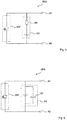
- Figure 1 shows an equivalent circuit diagram of an electrical circuit with a solar cell, that is to say a solar-powered electrical circuit SES.
- the circuit has a first connection A1 and a second connection A2.
- An energy converter EW is electrically coupled between the first connection A1 and the second connection A2.
- the energy converter EW has at least one solar cell SZ.
- An energy store ES is also electrically coupled between the first connection A1 and the second connection A2.
- the energy store ES has a solid-state accumulator FKA.
- the energy store EW and the solid-state accumulator FKA are connected in parallel to one another between the connections A1, A2.
- the energy store ES and the energy converter EW can be connected directly to the two connections A1 and A2.
- at least one circuit element e.g. B. the energy converter, is only electrically coupled to one of the connections via a further, optional circuit element.
- the two connections A1, A2 represent a port via which the energy converter EW and / or the energy store ES can be used further circuit components of the solar-powered electrical circuit SES can be connected.
- the energy store ES represents an energy source so that the in Figure 1 circuit components shown as an energy source for the in Figure 1 circuit elements, not shown, of the solar-powered electrical circuit can be used.
- the energy converter EW is provided to charge the energy store ES when the energy store ES is not fully charged and the energy converter can receive electromagnetic energy in the form of light via its solar cell. In the case of discrete time segments during which the electrical circuit SES is supplied with energy from an external environment, it is nevertheless possible to continuously provide a supply voltage and electrical energy at the connections A1, A2.
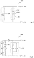
- FIG. 2 shows the possibility of connecting three solar cells in series in the energy converter EW.
- the solid-state accumulator FKA can have a working voltage that corresponds to three times the working voltage of a solar cell.
- a threefold series connection of solar cells adjusts the compatible voltages of energy converter EW and energy storage ES to one another.
- FIG 3 shows the use of a diode D, which is connected between the energy converter EW and the energy store ES.
- the diode D essentially serves to prevent the solid-state accumulator from being discharged via the solar cells in the dark.
- the diode D is connected in such a way that it has a has a low intrinsic resistance when charging the energy storage device and a high electrical resistance in the reverse current direction.
- FIG. 4 shows the possibility of connecting a varistor V parallel to the energy converter EW and parallel to the energy store ES.
- the varistor essentially serves as overvoltage protection for the solar cells or for the energy store ES.
- Figure 5 shows the possibility of using a resistive element RE, e.g. B. to connect an ohmic resistor in series with the solid state accumulator of the energy store ES.
- the resistive element essentially represents a series resistor that prevents excessive charging currents.
- FIG. 6 shows the possibility of connecting a capacitive element KE parallel to the solid-state accumulator in the energy store ES.
- the capacitive element e.g. B. a capacitor
- the capacitive element is essentially a backup capacitor that supports the solid state accumulator to provide energy for a single event.
- Solid-state accumulators are essentially characterized by a high energy density, but only by a low power density. A low power density can be compensated for by using the backup capacitor.
- the electrical circuit has the advantage of the high energy density of the solid state accumulator without having to directly accept the disadvantage of the low power density of the accumulator.
- Figure 7 shows the possibility of connecting two solid-state accumulators FKA1, FKA2 in series in the energy store ES.
- circuits shown above can be combined with one another in such a way that circuit properties suitable for a specific application are retained.
- FIG 8 shows a preferred embodiment with three series-connected solar cells in the energy converter and one resistive and one capacitive element in the energy store. Furthermore, the solar-powered electrical circuit SES has a varistor and a diode.
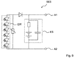
- Figure 9 shows a further embodiment in which six solar cells are connected in series in the energy converter EW to increase the voltage. Two accumulators are connected in series in the energy store ES.
- the electrical circuit can contain additional circuit components such as mechanical switches, sensors (e.g. for radiation, pressure, temperature, humidity, chemicals, gases and acceleration), radio modules for receiving or sending electromagnetic signals and other energy converters and energy stores and other passive and active (e.g. integrated electronic circuits for evaluating switching states or sensor measured values or for evaluating or creating received or transmitted radio signals).
- sensors e.g. for radiation, pressure, temperature, humidity, chemicals, gases and acceleration
- radio modules for receiving or sending electromagnetic signals and other energy converters and energy stores and other passive and active (e.g. integrated electronic circuits for evaluating switching states or sensor measured values or for evaluating or creating received or transmitted radio signals).
- passive and active e.g. integrated electronic circuits for evaluating switching states or sensor measured values or for evaluating or creating received or transmitted radio signals.
Landscapes
- Engineering & Computer Science (AREA)
- Power Engineering (AREA)
- Life Sciences & Earth Sciences (AREA)
- Sustainable Development (AREA)
- Sustainable Energy (AREA)
- Manufacturing & Machinery (AREA)
- Chemical & Material Sciences (AREA)
- Chemical Kinetics & Catalysis (AREA)
- Electrochemistry (AREA)
- General Chemical & Material Sciences (AREA)
- Charge And Discharge Circuits For Batteries Or The Like (AREA)
- Photovoltaic Devices (AREA)
Description
- Die Erfindung betrifft elektrische Schaltungen, z. B. für elektrische Systeme, die eine autarke Energieversorgung benötigen, und die Verwendung einer solchen Schaltung.
- Es gibt Situationen, in denen an bestimmten Positionen eine elektrische Schaltung mit elektrischer Energie versorgt werden muss, ohne dass an dieser Stelle ein Stromanschluss vorhanden ist. Werden beispielsweise Veränderungen nachträglich an Gebäuden vorgenommen, so können Stromkabel verlegt werden. Das Verlegen von Stromkabeln ist im Allgemeinen dabei kostenund arbeitsintensiv und kann das ästhetische Empfinden stören.
- Um beispielsweise einen Lichtschalter an einer Stelle ohne Stromversorgung anzuordnen und dort zu betreiben, kann ein Lichtschalter mit einem Funkmodul verwendet werden, wobei das Funkmodul durch eine übliche Batterie mit elektrischer Energie versorgt wird.
- Eine andere Möglichkeit besteht z. B. darin, einen Schalter mit einem magnetischen oder piezoelektrischen Energiekonverter zu verwenden, der Bewegungsenergie, z. B. Energie der Bewegung einer Betätigung des Schalters, in elektrische Energie wandelt (ein so genannter Harvester). Solche Harvester sind allerdings teuer in der Anschaffung und üblicherweise auch schwergängiger.
- Aus der
US 2008/001577 A1 sind elektrische Bauelemente mit Solarzelle zum Wiederaufladen eines Energiespeichers bekannt. - Aus den Dokumenten
CN 105553417 undCN101261047 sind ebenfalls elektrische Bauelemente mit Solarzelle und Energiespeicher bekannt. Aus derUS 5,631,535 A sind Steuerschaltungen zum Aufladen eines Energiespeichers, z. B. mittels Strom aus einer Solarzelle, bekannt. - Es besteht deshalb der Wunsch nach elektrischen Schaltungen, die sich in der Bedienung von konventionellen Schaltungen, z. B. Schaltern, nicht unterscheiden und bei denen nicht regelmäßig Batterien ersetzt werden müssen.
- Dazu gibt der unabhängige Anspruch eine entsprechende elektrische Schaltung an. Abhängige Ansprüche geben vorteilhafte Ausgestaltungen an.
- Die elektrische Schaltung hat einen Energiewandler, einen Energiespeicher, einen ersten Anschluss und einen zweiten Anschluss. Der Energiewandler ist mit dem ersten und mit dem zweiten Anschluss elektrisch gekoppelt. Der Energiespeicher ist ebenfalls mit dem ersten und zweiten Anschluss elektrisch gekoppelt. Der Energiewandler ist dazu geeignet und dazu bestimmt, den Energiespeicher in diskreten Zeitabschnitten aufzuladen. Der Energiespeicher ist dazu geeignet und bestimmt, kontinuierlich Energie bereitzustellen. Der Energiewandler umfasst zumindest eine Solarzelle. Der Energiespeicher umfasst zumindest einen Festkörperakkumulator.
- Der erste und der zweite Anschluss sind dabei im Wesentlichen die zwei Anschlüsse, über die die elektrische Schaltung elektrische Energie an weitere Schaltungskomponenten oder an eine externe Schaltungsumgebung abgeben kann. Der Energiewandler mit der Solarzelle ist dazu vorgesehen, elektromagnetische Energie, vorzugsweise im sichtbaren Spektrum, in elektrische Energie umzuwandeln. Der Energiespeicher mit seinem Festkörperakkumulator ist dazu vorgesehen, die vom Energiewandler zu bestimmten Zeitabschnitten, z. B. wenn Licht auf die Solarzelle fällt, entgegenzunehmen und zwischen zuspeichern. Das heißt, dass auch dann elektrische Energie an den beiden Anschlüssen (kontinuierlich) zur Verfügung gestellt wird, wenn kein Licht auf die Solarzelle fällt. Die elektrische Schaltung hat eine Energiequelle, die auch bei Dunkelheit Energie zur Verfügung stellt.
- Der Festkörperakkumulator des Energiespeichers ist eine Bauform von Akkumulatoren, bei der seine Elektroden und der Elektrolyt zwischen den Elektroden aus einem nicht flüssigen Material bestehen.
- Ein solcher Festkörperakkumulator kann mit kleinen Abmessungen und in einer Vielzahl unterschiedlicher physischer Formen hergestellt werden.
- Für den Anwender ergibt sich der Vorteil, dass nicht regelmäßig Batterien ersetzt werden müssen. Gleichzeitig entsteht kein zusätzlicher Platzbedarf und die Kosten sind im Vergleich zu Lösungen mit magnetischen oder piezoelektrischen Harvestern nicht erhöht bzw. sogar verringert.
- Ein gewohntes Schaltgefühl beim Betätigen eines Schalters, z. B. eines Lichtschalters, kann beibehalten werden.
- Durch die Verwendung eines Festkörperakkumulators entfällt die Gefahr eines auslaufenden Elektrolyten, der in konventionellen Akkumulatoren oft korrosive Eigenschaften hat. Im Übrigen ist die Gefahr von Selbstentzündungen des Festkörperackumulators verringert. Der Akkumulator kann in praktisch jeder beliebigen Form realisiert werden. Die mechanische Beständigkeit ist besser als bei konventionellen klassischen Batterien oder Akkumulatoren, zumindest wenn der Akkumulator besonders kleine Abmessungen haben soll und dazu ohne eine stabilisierende Außenhülle ausgestaltet ist.
- Als Materialien für die Elektroden oder für den Elektrolyten kommen die üblichen Materialien, die in Festkörperakkumulatoren Verwendung finden, in Frage.
- Es ist möglich, dass der Energiewandler und der Energiespeicher parallel verschaltet sind.
- In einer parallelen Verschaltung kann der Energiewandler, z. B. bei Lichteinfall, den Energiespeicher laden. Ferner können sowohl der Energiewandler als auch der Energiespeicher zusammen Energie an übrige Schaltungskomponenten abgeben, falls Energie beansprucht wird und gleichzeitig Licht auf die Solarzelle des Energiewandlers fällt.
- Es ist möglich, dass die elektrische Schaltung zusätzlich eine Diode umfasst. Die Diode kann zwischen dem Energiespeicher und dem Energiewandler verschaltet sein. Es ist möglich, dass die Diode in Serie zwischen einer Elektrode des Energiespeichers und einer Elektrode des Energiewandlers verschaltet ist.
- Die Diode dient dazu, den Energiespeicher vor einer Selbstentladung über den Energiewandler, z. B. bei Dunkelheit und einer endlichen Leitfähigkeit des Energiewandlers bei Dunkelheit, zu schützen.
- Die Diode ist dabei vorzugsweise so verschaltet, dass ihr eigener Widerstand möglichst gering ist, während der Energiewandler den Energiespeicher auflädt. Für die entgegengesetzte Stromrichtung ist die Diode dann in Sperrrichtung geschaltet.
- Die elektrische Schaltung weist ferner einen Varistor auf. Der Varistor ist parallel zum Energiespeicher und parallel zum Energiewandler verschaltet. Der Varistor ist ein Bauelement mit einem spannungsabhängigen Widerstand. Der elektrische Widerstand des Varistors nimmt dabei mit zunehmender angelegter Spannung ab.
- Bei einer niedrigen angelegten Spannung hat der Varistor vorzugsweise einen sehr hohen elektrischen Widerstand. Bei höheren Spannungen hat der Varistor vorzugsweise einen sehr niedrigen elektrischen Widerstand.
- Durch die Verwendung eines Varistors kann der Energiespeicher vor Überlastung geschützt werden, wenn beispielsweise der Energiewandler, z. B. bei starkem Lichteinfall und gefülltem Energiespeicher, oder übrige Schaltungskomponenten ein Übermaß an Energie bereitstellen.
- Der Varistor dient somit als Überspannungsschutz, insbesondere für die Solarzellen.
- Es ist möglich, dass die elektrische Schaltung zusätzlich ein resistives Element umfasst. Das resistive Element kann im Energiespeicher in Serie zum Festkörperakkumulator verschaltet sein.
- Das resistive Element, z. B. ein ohmscher Widerstand, kann somit einen Vorwiderstand darstellen, der einen zu hohen Ladestrom verhindert.
- Es ist möglich, dass die elektrische Schaltung zusätzlich ein kapazitives Element im Energiespeicher umfasst. Das kapazitive Element kann parallel zum Festkörperakkumulator verschaltet sein.
- Das kapazitive Element, z. B. ein Kondensator, kann einen Stützkondensator darstellen, der den Festkörperakkumulator beim Bereitstellen elektrischer Energie einer relativ hohen elektrischen Leistung, z. B. für einen einzelnen Schaltvorgang, zur Verfügung stellt.
- Festkörperakkumulatoren haben einen vergleichsweise hohen Innenwiderstand, der mit dem Kondensator kompensiert wird.
- Es ist möglich, dass der Energiewandler drei oder sechs Solarzellen umfasst. Die Solarzellen können dabei in Serie verschaltet sein. Zusätzlich kann der Energiespeicher einen oder zwei Festkörperakkumulatoren umfassen, die in Serie verschaltet sind.
- Eine einzelne Solarzelle kann eine Spannung von etwa 0,5 V zur Verfügung stellen, wenn sie entsprechend viel Licht empfängt.
- Ein Festkörperakkumulator kann eine übliche Versorgungsspannung in Höhe von etwa 1,5 V bereitstellen, wenn er geladen ist.
- Ein Festkörperakkumulator mit der Versorgungsspannung von etwa 1,5 V kann dabei übliche Batterien mit einer Versorgungsspannung von 1,5 V ersetzen.
- Drei Solarzellen, die in Serie verschaltet sind und jeweils eine einzelne Versorgungsspannung von 0,5 V bereitstellen können, können zusammen eine Versorgungsspannung von etwa 1,5 V bereitstellen und sind damit gut geeignet, den Festkörperakkumulator mit einer Versorgungsspannung von 1,5 V aufzuladen.
- Entsprechendes gilt für die zugehörigen Mehrfachen der Versorgungsspannungen. So können sechs in Serie verschaltete Solarzellen eine Serienverschaltung von zwei Akkumulatoren aufladen. Zwei in Serie verschaltete Akkumulatoren können dabei eine Versorgungsspannung von 3 V bereitstellen. Eine derartige elektrische Verschaltung kann einen Ersatz für eine Spannungsversorgung mit zwei in Serie geschalteten üblichen Batterien darstellen.
- Entsprechend kann die elektrische Schaltung auch drei, vier, fünf, sechs, sieben, acht, neun oder zehn Festkörperakkumulatoren und entsprechend neun, zwölf, fünfzehn, achtzehn, 21, 24, 27 oder dreißig Solarzellen in Energiespeicher umfassen.
- Es ist möglich, dass der Festkörperakkumulator als reflowlötbares SMD-Bauelement realisiert ist. Dies kann bei konventionellen Batterien oder Akkumulatoren sonst nicht oder nur mit einem unverhältnismäßig hohen technischen Aufwand und entsprechenden Kosten realisiert werden.
- Reflow-Löten (Wiederaufschmelzlöten) ist dabei ein Weichlötverfahren zum Löten von SMD-Bauelementen. Festkörperakkumulatoren eignen sich gut zum Reflow-Löten, da ihre Bestandteile die beim Reflow-Löten auftretenden Temperaturen zumindest für die relativ kurze Zeit des Lötens gut aushalten, ohne dass der Festkörperakkumulator beschädigt wird. Das Gleiche gilt auch für die übrigen Schaltungskomponenten der elektrischen Schaltung.
- Die Verwendung eines Festkörperakkumulators als SMD-Bauelement (SMD = Surface-Mounted Device (oberflächenmontiertes Bauelement)) hat den Vorteil, dass der Akkumulator leicht mit gängigen Verschaltungs- und Verbindungstechnologien zu seinen übrigen Schaltungskomponenten hinzugefügt werden kann und die elektrische Schaltung entsprechend relativ kostengünstig und mit einer geringen Ausschussquote hergestellt werden kann.
- Es ist möglich, dass zumindest eine Schaltungskomponente in einem keramischen Mehrlagensubstrat eingebettet ist.
- Ein keramisches Mehrlagensubstrat hat dabei zum eine keramische Lage und eine Metallisierungslage. In einer oder mehreren übereinander angeordneten Metallisierungslagen können passive Schaltungselemente, z. B. resistive Elemente, kapazitive Elemente und/oder induktive Elemente als metallisierte Strukturen gebildet sein. Das dielektrische Material der keramischen Lagen zwischen den Metallisierungslagen dient als elektrischer Isolator zwischen den Metallisierungslagen und als mechanischer Träger, der das Substrat stabilisiert. Unterschiedliche Schaltungselemente in unterschiedlichen Metallisierungslagen können durch so genannte Vias miteinander verbunden und verschaltet sein. Ein solches keramisches Mehrlagenträgersubstrat kann an seiner Oberseite oder an seiner Unterseite weitere Schaltungskomponenten, z. B. SMD-Bauelemente, aufweisen.
- Das keramische Mehrlagensubstrat kann z. B. ein LTCC-Substrat (LTCC = Low-Temperature Co-fired Ceramics) oder ein HTCC-Trägersubstrat (HTTC = High-Temperature Co-fired Ceramics) sein.
- Im keramischen Trägersubstrat können Ausnehmungen vorgesehen sein, in der zumindest eine oder mehrere Schaltungskomponenten, z. B. eine Solarzelle oder ein Festkörperakkumulator, eingebettet ist.
- Durch das Einbetten von Schaltungskomponenten, z. B. ein monolithisches Einbetten von Schaltungskomponenten im Substrat wird die Bauhöhe des entsprechenden Bauelements, in dem die elektrische Schaltung realisiert ist, verringert.
- Es ist möglich, dass zumindest zwei unterschiedliche Schaltungskomponenten in einem Modul baulich zusammengefasst sind.
- Auch mehr als zwei Schaltungskomponenten können in einem einzigen Modul zusammengefasst sein. Die Schaltungskomponenten können monolithisch im Modul integriert sein. Das Modul kann SMD-montierbar ausgestaltet sein. So können z. B. der Festkörperakkumulator, die Solarzellen und weitere passive Schaltungskomponenten in einem einzigen SMD-montierbaren Modul zusammengefasst sein.
- Es ist möglich, dass zumindest ein Schaltungselement in einem Gehäuse angeordnet ist, dessen Form und Größe der Form und Größe einer handelsüblichen Batterie nachempfunden ist, sodass das Gehäuse in eine Fassung für eine solche Batterie einlegbar ist.
- So ist es möglich, dass ein Modul, in dem zwei oder mehrere Schaltungskomponenten zusammengefasst sind, in der Außengeometrie einer Batterie, z. B. einer Knopfzelle, ausgestaltet ist. Ein solches Modul kann eine übliche Batterie, z. B. eine übliche Knopfzelle, ersetzen oder zumindest deren Aufnahme verwenden. In bestehenden Schaltungen ist damit kein Umdesign notwendig.
- Die Dimensionierung der Kapazität des Energiespeichers und der Leistung der Solarzelle können so gewählt sein, dass übliche Anforderungen erfüllt sind und dennoch geringe Herstellungskosten und geringe Abmessungen eingehalten werden können.
- Wird beispielsweise ein Raum mit einer LED-Lampe in drei Meter Entfernung beleuchtet und hat die LED-Lampe eine Leistung von 10 W und hat die Solarzelle eine Fläche von etwa 4 cm2 und einen Wirkungsgrad von 10 %, beträgt die Ausgangsleistung der Solarzelle etwa 0,7 µW. Ist die elektrische Schaltung ein Funk-Lichtschalter und benötigt ein einzelner Schaltvorgang etwa 100 µJ, beträgt die Ladezeit für einen einzelnen Schaltvorgang weniger als drei Minuten. Die Speicherkapazität des Festkörperakkumulators kann ca. 500 mJ betragen. Damit hat ein aufgeladener Festkörperakkumulator Energie für weit über tausend Schaltvorgänge.
- Eine oben beschriebene elektrische Schaltung kann entsprechend als Energieversorgung in einer autarken Schaltung Verwendung finden.
- Es ist möglich, dass die autarke Schaltung ausgewählt ist aus einer Funkschaltung, einem Lichtschalter, einer Alarmanlage, einem Brandmelder, einer Uhr, z. B. einer Wanduhr oder einer Standuhr, einer Fernbedienung, einer Wetterstation und eines Bewegungsmelders.
- Es ist möglich, dass die autarke Schaltung ein Sensor, z. B. ein Funksensor, ist.
- Es ist dann möglich, dass der Sensor dazu ausgestaltet ist, eine Strahlung, einen Druck, eine Temperatur, eine Feuchtigkeit, die Anwesenheit einer chemischen Substanz, ein Gas oder eine Beschleunigung zu detektieren. Es ist auch möglich, dass der Sensor dazu ausgestaltet ist, eine beliebige Kombination der diesen Paramtern zugehörigen Messgrößen zu bestimmen.
- Ein Modul, in dem die Schaltung realisiert ist, kann Abmessungen (Länge x Breite) von etwa 0,305 cm x 0,254 cm aufweisen. Ein solches Modul kann also sehr kompakt gebaut werden.
- Der vorliegenden elektrischen Schaltung zugrundeliegende Funktionsprinzipien und Wirkungsweisen und Details bevorzugter Ausführungsformen sind in den schematischen Figuren näher erläutert.
- Es zeigen:
- Figur 1:
- ein Ersatzschaltbild einer solarbetriebenen elektrischen Schaltung.
- Figur 2:
- eine elektrische Schaltung mit drei in Serie verschalteten Solarzellen.
- Figur 3:
- ein Ersatzschaltbild mit einer Diode.
- Figur 4:
- ein Ersatzschaltbild mit einem Varistor.
- Figur 5:
- ein Ersatzschaltbild mit einem resistiven Element.
- Figur 6:
- ein Ersatzschaltbild mit einem kapazitiven Element.
- Figur 7:
- ein Ersatzschaltbild mit zwei in Serie verschalteten Festkörperakkumulatoren.
- Figur 8:
- ein Ersatzschaltbild mit mehreren bevorzugten zusätzlichen Schaltungselementen.
- Figur 9:
- ein Ersatzschaltbild einer möglichen Ausgestaltung der solarbetriebenen elektrischen Schaltung.
-
Figur 1 zeigt ein Ersatzschaltbild einer elektrischen Schaltung mit einer Solarzelle, also einer solarbetriebenen elektrischen Schaltung SES. Die Schaltung hat einen ersten Anschluss A1 und einen zweiten Anschluss A2. Zwischen dem ersten Anschluss A1 und dem zweiten Anschluss A2 ist ein Energiewandler EW elektrisch gekoppelt. Der Energiewandler EW hat zumindest eine Solarzelle SZ. Ebenfalls zwischen dem ersten Anschluss A1 und dem zweiten Anschluss A2 ist ein Energiespeicher ES elektrisch gekoppelt. Der Energiespeicher ES hat einen Festkörperakkumulator FKA. Der Energiespeicher EW und der Festkörperakkumulator FKA sind parallel zueinander zwischen den Anschlüssen A1, A2 verschaltet. - Der Energiespeicher ES und der Energiewandler EW können direkt mit den beiden Anschlüssen A1 und A2 verschaltet sein. Es ist allerdings auch möglich, dass zumindest ein Schaltungselement, z. B. der Energiewandler, über ein weiteres, optionales Schaltungselement mit einem der Anschlüsse lediglich elektrisch gekoppelt ist.
- Die beiden Anschlüsse A1, A2 stellen einen Port dar, über den der Energiewandler EW und/oder der Energiespeicher ES mit weiteren Schaltungskomponenten der solarbetriebenen elektrischen Schaltung SES verschaltet sein können. Insbesondere der Energiespeicher ES stellt dabei eine Energiequelle dar, sodass die in
Figur 1 gezeigten Schaltungskomponenten als Energiequelle für die inFigur 1 nicht gezeigten Schaltungselemente der solarbetriebenen elektrischen Schaltung dienen können. - Der Energiewandler EW ist dazu vorgesehen, den Energiespeicher ES dann aufzuladen, wenn der Energiespeicher ES nicht vollständig geladen ist und der Energiewandler elektromagnetische Energie in Form von Licht über seine Solarzelle empfangen kann. Bei diskreten Zeitabschnitten, während der die elektrische Schaltung SES mit Energie einer externen Umgebung versorgt wird, ist es dennoch möglich, kontinuierlich an den Anschlüssen A1, A2 eine Versorgungsspannung und elektrische Energie bereitzustellen.
-
Figur 2 zeigt die Möglichkeit, drei Solarzellen in Serie im Energiewandler EW zu verschalten. Der Festkörperakkumulator FKA kann dabei eine Arbeitsspannung haben, die der dreifachen Arbeitsspannung einer Solarzelle entspricht. Entsprechend gleicht eine dreifache Serienverschaltung von Solarzellen die kompatiblen Spannungen von Energiewandler EW und Energiespeicher ES aneinander an. -
Figur 3 zeigt die Verwendung einer Diode D, die zwischen dem Energiewandler EW und dem Energiespeicher ES verschaltet ist. Die Diode D dient im Wesentlichen dazu, eine Entladung des Festkörperakkumulators bei Dunkelheit über die Solarzellen zu verhindern. Dazu ist die Diode D so geschaltet, dass sie einen geringen Eigenwiderstand beim Aufladen des Energiespeichers und einen hohen elektrischen Widerstand in der umgekehrten Stromrichtung hat. -
Figur 4 zeigt die Möglichkeit, einen Varistor V parallel zum Energiewandler EW und parallel zum Energiespeicher ES zu verschalten. Der Varistor dient dabei im Wesentlichen als Überspannungsschutz für die Solarzellen bzw. für den Energiespeicher ES. -
Figur 5 zeigt die Möglichkeit, ein resistives Element RE, z. B. einen ohmschen Widerstand, in Serie zum Festkörperakkumulator des Energiespeichers ES zu verschalten. Das resistive Element stellt dabei im Wesentlichen einen Vorwiderstand dar, der zu hohe Ladeströme verhindert. -
Figur 6 zeigt die Möglichkeit, ein kapazitives Element KE parallel zum Festkörperakkumulator im Energiespeicher ES zu verschalten. Das kapazitive Element, z. B. ein Kondensator, stellt dabei im Wesentlich einen Stützkondensator dar, der den Festkörperakkumulator unterstützt, um Energie für ein einzelnes Ereignis zur Verfügung zu stellen. Festkörperakkumulatoren sind im Wesentlichen durch eine hohe Energiedichte, aber durch eine lediglich niedrig Leistungsdichte gekennzeichnet. Eine niedrige Leistungsdichte kann dabei durch die Verwendung des Stützkondensators kompensiert werden. Dadurch hat die elektrische Schaltung den Vorteil der hohen Energiedichte des Festkörperakkumulators, ohne direkt den Nachteil der niedrigen Leistungsdichte des Akkumulators hinnehmen zu müssen. -
Figur 7 zeigt die Möglichkeit, zwei Festkörperakkumulatoren FKA1, FKA2 in Serie im Energiespeicher ES zu verschalten. Durch die Wahl des Grads der Kaskadierung einer entsprechenden Serien- oder Parallelverschaltung einzelner Festkörperackumulatoren im Energiespeicher ES ist es möglich, die elektrische Schaltung an eine Vielzahl unterschiedlicher Anforderungen bezüglich der Versorgungsspannung oder des Versorgungsstroms anzupassen. - Die oben gezeigten einzelnen Merkmale der Schaltungen können dabei so miteinander kombiniert werden, dass für einen konkreten Anwendungsfall geeignete Schaltungseigenschaften erhalten bleiben.
-
Figur 8 zeigt entsprechend eine bevorzugte Ausführungsform mit drei in Serie verschalteten Solarzellen im Energiewandler und einem resistiven und einem kapazitiven Element im Energiespeicher. Ferner hat die solarbetriebene elektrische Schaltung SES einen Varistor und eine Diode. -
Figur 9 zeigt eine weitere Ausgestaltung, bei der zur Erhöhung der Spannung sechs Solarzellen im Energiewandler EW in Serie geschaltet sind. Im Energiespeicher ES sind zwei Akkumulatoren in Serie geschaltet. - Die elektrische Schaltung kann zusätzliche Schaltungskomponenten wie mechanische Schalter, Sensoren (z. B. für Strahlung, Druck, Temperatur, Feuchtigkeit, Chemikalien, Gase und Beschleunigung), Funkmodule zum Empfangen oder Senden elektromagnetischer Signale und weitere Energiewandler und Energiespeicher und weitere passive und aktive (z. B. integrierte elektronische Schaltungen zum Auswerten von Schaltzuständen oder von Sensormesswerten oder zum Auswerten oder Erstellen von empfangenen oder zu sendenden Funksignalen) umfassen. Weiter kann die elektrische Schaltung Schaltungskomponenten, die über die Anschlüsse A1, A2 mit elektrischer Energie versorgt werden können, umfassen.
-
- A1, A2:
- erster, zweiter Anschluss
- D:
- Diode
- ES:
- Energiespeicher
- EW:
- Energiewandler
- FKA:
- Festkörperakkumulator
- KE:
- kapazitives Element
- RE:
- resistives Element
- SES:
- (solarbetriebene) elektrische Schaltung
- SZ:
- Solarzelle
- V:
- Varistor
Claims (14)
- Elektrische Schaltung (SES), umfassend- einen Energiewandler (EW),- einen Energiespeicher (ES),- einen ersten Anschluss (A1) und einen zweiten Anschluss (A2)wobei- der Energiewandler (EW) mit dem ersten (A1) und dem zweiten (A2) Anschluss elektrisch gekoppelt ist,- der Energiespeicher (ES) mit dem ersten (A1) und dem zweiten (A2) Anschluss elektrisch gekoppelt ist,- der Energiewandler (EW) dazu geeignet und bestimmt ist, den Energiespeicher (ES) in diskreten Zeitabschnitten aufzuladen,- der Energiewandler (EW) eine Solarzelle (SW) umfasst und- der Energiespeicher (ES) einen Festkörperakkumulator (FKA) umfasst,ferner umfassend einen Varistor (V), der parallel zum Energiespeicher (ES) und parallel zum Energiewandler (EW) verschaltet ist und dadurch gekennzeichnet ist, dass die elektrische Schaltung derart konfiguriert ist, eine kontinuierliche Energieabgabe an beiden Anschlüssen des Festköperakkumulators bereitzustellen.
- Elektrische Schaltung nach dem vorherigen Anspruch, wobei der Energiewandler (EW) und der Energiespeicher (ES) parallel verschaltet sind.
- Elektrische Schaltung nach einem der vorherigen Ansprüche, ferner umfassend eine Diode (D), die zwischen dem Energiespeicher (ES) und dem Energiewandler (EW) verschaltet ist.
- Elektrische Schaltung nach einem der vorherigen Ansprüche, ferner umfassend ein resistives Element (RE) im Energiespeicher (ES), das in Serie zum Festkörperakkumulator (FKA) verschaltet ist.
- Elektrische Schaltung nach einem der vorherigen Ansprüche, ferner umfassend ein kapazitives Element (KE) im Energiespeicher (ES), das parallel zum Festkörperakkumulator (FKA) verschaltet ist.
- Elektrische Schaltung nach einem der vorherigen Ansprüche, wobei- der Energiewandler (EW) drei oder sechs Solarzellen (SZ), die in Serie verschaltet sind, umfasst und- der Energiespeicher (ES) einen oder zwei Festkörperakkumulatoren (FKA), die in Serie verschaltet sind, umfasst.
- Elektrische Schaltung nach einem der vorherigen Ansprüche, wobei zumindest ein Festkörperakkumulator (FKA) als reflowlötbares SMD-Bauelement realisiert ist.
- Elektrische Schaltung nach einem der vorherigen Ansprüche, wobei zumindest eine Schaltungskomponente in einem keramischen Mehrlagensubstrat eingebettet ist.
- Elektrische Schaltung nach einem der vorherigen Ansprüche, wobei zumindest zwei unterschiedliche Schaltungskomponenten in einem Modul baulich zusammengefasst sind.
- Elektrische Schaltung nach einem der vorherigen Ansprüche, wobei zumindest ein Schaltungselement in einem Gehäuse angeordnet ist, dessen Form und Größe der Form und Größe einer handelsüblichen Batterie nachempfunden ist, so dass das Gehäuse in eine Fassung für eine solche Batterie einlegbar ist.
- Verwendung einer elektrischen Schaltung nach einem der vorherigen Ansprüche als Energieversorgung in einer autarken Schaltung.
- Verwendung nach dem vorherigen Anspruch, wobei die autarke Schaltung ausgewählt ist aus einer Funkschaltung, einem Lichtschalter, einer Alarmanlage, einem Brandmelder, einem einer Uhr, einer Fernbedienung, einer Wetterstation und eines Bewegungsmelders.
- Verwendung nach Anspruch 12, wobei die autarke Schaltung ausgewählt ist aus einem Sensor und einem Funksensor.
- Verwendung nach dem vorherigen Anspruch, wobei der Sensor dazu ausgestaltet ist, eine Strahlung, einen Druck, eine Temperatur, eine Feuchtigkeit, die Anwesenheit einer chemischen Substanz, ein Gas oder eine Beschleunigung oder eine beliebige Kombination hiervon zu detektieren.
Applications Claiming Priority (2)
| Application Number | Priority Date | Filing Date | Title |
|---|---|---|---|
| DE102017111946.9A DE102017111946A1 (de) | 2017-05-31 | 2017-05-31 | Elektrische Schaltung und Verwendung der elektrischen Schaltung |
| PCT/EP2018/062773 WO2018219653A1 (de) | 2017-05-31 | 2018-05-16 | Elektrische schaltung und verwendung der elektrischen schaltung |
Publications (2)
| Publication Number | Publication Date |
|---|---|
| EP3631975A1 EP3631975A1 (de) | 2020-04-08 |
| EP3631975B1 true EP3631975B1 (de) | 2021-10-06 |
Family
ID=62530181
Family Applications (1)
| Application Number | Title | Priority Date | Filing Date |
|---|---|---|---|
| EP18729337.8A Active EP3631975B1 (de) | 2017-05-31 | 2018-05-16 | Elektrische schaltung und verwendung der elektrischen schaltung |
Country Status (6)
| Country | Link |
|---|---|
| US (1) | US11522386B2 (de) |
| EP (1) | EP3631975B1 (de) |
| JP (1) | JP2020520214A (de) |
| CN (1) | CN110663172A (de) |
| DE (1) | DE102017111946A1 (de) |
| WO (1) | WO2018219653A1 (de) |
Families Citing this family (2)
| Publication number | Priority date | Publication date | Assignee | Title |
|---|---|---|---|---|
| DE102017111942B9 (de) * | 2017-05-31 | 2025-04-03 | Tdk Electronics Ag | Hybride Energieversorgungsschaltung und Verwendung einer hybriden Energieversorgungsschaltung |
| DE102019135497B4 (de) * | 2019-12-20 | 2021-11-11 | Nova Plasma Ltd | Piezoelektrischer Plasmagenerator und Verfahren zum Betrieb eines piezoelektrischen Plasmagenerators |
Citations (2)
| Publication number | Priority date | Publication date | Assignee | Title |
|---|---|---|---|---|
| US5631535A (en) * | 1995-06-07 | 1997-05-20 | Franklin Electric Co., Inc. | Regulator for charging a rechargeable storage device from a photovoltaic cell |
| CN101261047A (zh) * | 2007-03-07 | 2008-09-10 | 刘树强 | 太阳能集热器光电测控装置 |
Family Cites Families (42)
| Publication number | Priority date | Publication date | Assignee | Title |
|---|---|---|---|---|
| US3921049A (en) * | 1973-09-25 | 1975-11-18 | Union Carbide Corp | Charging circuit for battery-operated devices powered by solar cells |
| JPS5428260B2 (de) | 1974-09-02 | 1979-09-14 | ||
| JPS52119872U (de) | 1976-03-09 | 1977-09-10 | ||
| US4465586A (en) | 1982-06-14 | 1984-08-14 | Exxon Research & Engineering Co. | Formation of optically anisotropic pitches |
| JPS596843A (ja) | 1982-07-05 | 1984-01-13 | Taiyo Yushi Kk | レシチン含有油脂組成物 |
| JPS5963672A (ja) | 1982-09-30 | 1984-04-11 | Japan Storage Battery Co Ltd | ニツケル−亜鉛蓄電池 |
| JPS5963673A (ja) * | 1982-10-01 | 1984-04-11 | Hitachi Ltd | 光電池 |
| JPS60118775U (ja) | 1984-01-20 | 1985-08-10 | 住友電気工業株式会社 | 単導体送電線のセンサ用電源装置 |
| JPS62274286A (ja) | 1986-05-23 | 1987-11-28 | Fuji Electric Co Ltd | 放射線エリヤモニタ装置 |
| US4740431A (en) | 1986-12-22 | 1988-04-26 | Spice Corporation | Integrated solar cell and battery |
| JPH048449Y2 (de) | 1987-11-07 | 1992-03-03 | ||
| JPH0714110B2 (ja) | 1988-08-17 | 1995-02-15 | 株式会社村田製作所 | 多層セラミック基板 |
| JPH0314933U (de) | 1989-06-27 | 1991-02-14 | ||
| JPH0374999A (ja) | 1989-08-17 | 1991-03-29 | Toshiba Corp | ワイヤレスリモートコントロール装置 |
| JPH0759271A (ja) | 1991-09-13 | 1995-03-03 | S Ii Project Kk | 太陽発電ー蓄電システム |
| JPH07311889A (ja) | 1994-05-17 | 1995-11-28 | Tokyo Gas Co Ltd | ガス検知器 |
| JPH0916277A (ja) * | 1995-04-24 | 1997-01-17 | Canon Inc | 太陽電池を有する直流電源システムおよびその動作方法 |
| JP2001135364A (ja) | 1999-10-29 | 2001-05-18 | Honda Motor Co Ltd | 光充電式電池 |
| JP3531866B2 (ja) | 2000-07-28 | 2004-05-31 | 独立行政法人 科学技術振興機構 | 薄膜固体リチウムイオン二次電池 |
| US8212138B2 (en) * | 2003-05-16 | 2012-07-03 | The United States Of America As Represented By The Administrator Of National Aeronautics And Space Administration | Reverse bias protected solar array with integrated bypass battery |
| JP4133924B2 (ja) * | 2004-05-14 | 2008-08-13 | Necトーキン株式会社 | 電源装置 |
| JP2008504665A (ja) | 2004-08-20 | 2008-02-14 | エルジー・ケム・リミテッド | 定電圧素子を有する2次電池 |
| EP1911101B1 (de) * | 2005-07-20 | 2011-05-04 | Ecosol Solar Technologies Inc. | Photovoltaische stromausgabebenutzende einrichtung |
| US8866465B2 (en) * | 2005-08-29 | 2014-10-21 | The Aerospace Corporation | Nanosatellite photovoltaic regulator |
| DE102006026661B4 (de) * | 2006-02-14 | 2008-10-09 | Diehl Ako Stiftung & Co. Kg | Photovoltaikanlage |
| KR20090033451A (ko) * | 2006-06-30 | 2009-04-03 | 사임베트 코퍼레이션 | 박막 밧데리 재충전 시스템 및 방법 |
| US7724145B2 (en) * | 2006-07-20 | 2010-05-25 | Intelleflex Corporation | Self-charging RFID tag with long life |
| US7847512B2 (en) * | 2008-03-20 | 2010-12-07 | Min Carroll | Solar powered DC load system |
| US9136732B2 (en) * | 2011-10-15 | 2015-09-15 | James F Wolter | Distributed energy storage and power quality control in photovoltaic arrays |
| CN102496749A (zh) | 2011-12-28 | 2012-06-13 | 普乐新能源(蚌埠)有限公司 | 集成薄膜太阳能电池的一体化薄膜固态蓄电池 |
| US20140034815A1 (en) * | 2012-08-06 | 2014-02-06 | Agency For Science, Technology And Research | Self-powered photodetector and method of fabrication thereof |
| US10193193B2 (en) * | 2013-07-19 | 2019-01-29 | Itm Semiconductor Co., Ltd | Structure of battery protection circuit module package coupled with holder, and battery pack having same |
| UA107542C2 (uk) * | 2014-01-24 | 2015-01-12 | Товариство З Обмеженою Відповідальністю "Техінвест-Еко" | Спосіб та пристрій для відбору електричної енергії від фотоелектричного модуля |
| US20170077868A1 (en) * | 2014-02-21 | 2017-03-16 | Philips Lighting Holding B.V. | Power point tracking via solar-battery-converter |
| JP6395806B2 (ja) * | 2014-03-03 | 2018-09-26 | セイコーインスツル株式会社 | 電子機器および制御方法 |
| CN105553417A (zh) | 2014-10-30 | 2016-05-04 | 鑫邦国际科技股份有限公司 | 具固态电池的太阳能电池模块 |
| BR112017025616A2 (en) * | 2015-06-01 | 2018-08-07 | The Board Of Trustees Of The University Of Illinois | alternative approach to uv capture |
| JP6481571B2 (ja) * | 2015-09-14 | 2019-03-13 | オムロン株式会社 | 検査装置および検査方法 |
| JP6646218B2 (ja) * | 2016-03-28 | 2020-02-14 | 富士通株式会社 | 充電回路及び電子装置 |
| JP6194084B1 (ja) * | 2016-08-31 | 2017-09-06 | 株式会社フジクラ | 光電変換装置 |
| JP6772784B2 (ja) * | 2016-11-25 | 2020-10-21 | 富士通株式会社 | 電源制御回路、環境発電装置および環境発電装置の制御方法 |
| US11032895B1 (en) * | 2018-12-03 | 2021-06-08 | Katerra Inc. | Wireless light switch with energy management control |
-
2017
- 2017-05-31 DE DE102017111946.9A patent/DE102017111946A1/de not_active Withdrawn
-
2018
- 2018-05-16 EP EP18729337.8A patent/EP3631975B1/de active Active
- 2018-05-16 US US16/607,272 patent/US11522386B2/en active Active
- 2018-05-16 CN CN201880035888.9A patent/CN110663172A/zh active Pending
- 2018-05-16 JP JP2019558568A patent/JP2020520214A/ja active Pending
- 2018-05-16 WO PCT/EP2018/062773 patent/WO2018219653A1/de not_active Ceased
Patent Citations (2)
| Publication number | Priority date | Publication date | Assignee | Title |
|---|---|---|---|---|
| US5631535A (en) * | 1995-06-07 | 1997-05-20 | Franklin Electric Co., Inc. | Regulator for charging a rechargeable storage device from a photovoltaic cell |
| CN101261047A (zh) * | 2007-03-07 | 2008-09-10 | 刘树强 | 太阳能集热器光电测控装置 |
Also Published As
| Publication number | Publication date |
|---|---|
| JP2020520214A (ja) | 2020-07-02 |
| EP3631975A1 (de) | 2020-04-08 |
| DE102017111946A1 (de) | 2018-12-06 |
| US20200287405A1 (en) | 2020-09-10 |
| CN110663172A (zh) | 2020-01-07 |
| US11522386B2 (en) | 2022-12-06 |
| WO2018219653A1 (de) | 2018-12-06 |
Similar Documents
| Publication | Publication Date | Title |
|---|---|---|
| EP3631975B1 (de) | Elektrische schaltung und verwendung der elektrischen schaltung | |
| DE3426199C2 (de) | Überbrückungselement | |
| CN100594607C (zh) | 内埋式的多功能整合型结构及其制作方法 | |
| EP3632191A1 (de) | Leiterplatte mit stromversorgung, elektrisches bauelement mit leiterplatte und verfahren zur herstellung einer leiterplatte | |
| DE19954259B4 (de) | Dünnschicht-Photovoltaikmodul mit integrierter Flachantennenstruktur | |
| DE19601616A1 (de) | Stromversorgungseinrichtung, insbesondere für elektrisch betriebene Meßinstrumente | |
| DE102017111942B4 (de) | Hybride Energieversorgungsschaltung und Verwendung einer hybriden Energieversorgungsschaltung | |
| DE102010018875A1 (de) | Piezogenerator mit verschiedenen Piezoelementen und elektronische Schaltung | |
| EP3069397B1 (de) | Energieversorgungsvorrichtung | |
| EP1454366A2 (de) | Dünnschichtenergiesystem | |
| EP0270044A2 (de) | Sicherung | |
| DE10053357C1 (de) | Spannungsquelle in Form einer Knopfzelle | |
| EP3317901A1 (de) | Optimiertes photovoltaik-modul mit bypass-netzwerk | |
| DE202022100068U1 (de) | Batterievorrichtung im Metallgehäuse mit unabhängiger Überwachung | |
| DE102010062559A1 (de) | Mikroelektromechanisches Sensormodul sowie entsprechendes Herstellungsverfahren | |
| DE3634581C2 (de) | Statischer Verstärker für schwache Signale | |
| KR102249909B1 (ko) | 튜너블 커패시터 및 이를 이용한 에너지 수집장치 | |
| DE102010056338B4 (de) | Anordnung mit mindestens einer Farbstoffsolarzelle | |
| EP1911052B1 (de) | Elektrisches bauelement | |
| EP1475853A1 (de) | Flexible Energieträger-Systeme für mobile elektrische Geräte | |
| DE102013215152A1 (de) | Feldgeräteanordnung | |
| DE102022003440A1 (de) | Batteriemodul mit Pol-Kontaktfläche | |
| DE102015202908A1 (de) | Elektrochemische Zelle | |
| WO2012038059A2 (de) | Konditionierung einer solarzelle | |
| DE2137311A1 (de) | Gasdichter knopfakkumulator |
Legal Events
| Date | Code | Title | Description |
|---|---|---|---|
| STAA | Information on the status of an ep patent application or granted ep patent |
Free format text: STATUS: UNKNOWN |
|
| STAA | Information on the status of an ep patent application or granted ep patent |
Free format text: STATUS: THE INTERNATIONAL PUBLICATION HAS BEEN MADE |
|
| PUAI | Public reference made under article 153(3) epc to a published international application that has entered the european phase |
Free format text: ORIGINAL CODE: 0009012 |
|
| STAA | Information on the status of an ep patent application or granted ep patent |
Free format text: STATUS: REQUEST FOR EXAMINATION WAS MADE |
|
| 17P | Request for examination filed |
Effective date: 20190930 |
|
| AK | Designated contracting states |
Kind code of ref document: A1 Designated state(s): AL AT BE BG CH CY CZ DE DK EE ES FI FR GB GR HR HU IE IS IT LI LT LU LV MC MK MT NL NO PL PT RO RS SE SI SK SM TR |
|
| AX | Request for extension of the european patent |
Extension state: BA ME |
|
| RIN1 | Information on inventor provided before grant (corrected) |
Inventor name: MELISCHNIG, ALEXANDER Inventor name: OISHI, MASAHIRO Inventor name: PICHLER, JOHANN Inventor name: RINNER, FRANZ |
|
| DAV | Request for validation of the european patent (deleted) | ||
| DAX | Request for extension of the european patent (deleted) | ||
| STAA | Information on the status of an ep patent application or granted ep patent |
Free format text: STATUS: EXAMINATION IS IN PROGRESS |
|
| 17Q | First examination report despatched |
Effective date: 20201211 |
|
| GRAP | Despatch of communication of intention to grant a patent |
Free format text: ORIGINAL CODE: EPIDOSNIGR1 |
|
| STAA | Information on the status of an ep patent application or granted ep patent |
Free format text: STATUS: GRANT OF PATENT IS INTENDED |
|
| INTG | Intention to grant announced |
Effective date: 20210428 |
|
| GRAS | Grant fee paid |
Free format text: ORIGINAL CODE: EPIDOSNIGR3 |
|
| GRAA | (expected) grant |
Free format text: ORIGINAL CODE: 0009210 |
|
| STAA | Information on the status of an ep patent application or granted ep patent |
Free format text: STATUS: THE PATENT HAS BEEN GRANTED |
|
| AK | Designated contracting states |
Kind code of ref document: B1 Designated state(s): AL AT BE BG CH CY CZ DE DK EE ES FI FR GB GR HR HU IE IS IT LI LT LU LV MC MK MT NL NO PL PT RO RS SE SI SK SM TR |
|
| REG | Reference to a national code |
Ref country code: GB Ref legal event code: FG4D Free format text: NOT ENGLISH |
|
| REG | Reference to a national code |
Ref country code: CH Ref legal event code: EP Ref country code: AT Ref legal event code: REF Ref document number: 1437066 Country of ref document: AT Kind code of ref document: T Effective date: 20211015 |
|
| REG | Reference to a national code |
Ref country code: IE Ref legal event code: FG4D Free format text: LANGUAGE OF EP DOCUMENT: GERMAN |
|
| REG | Reference to a national code |
Ref country code: DE Ref legal event code: R096 Ref document number: 502018007364 Country of ref document: DE |
|
| REG | Reference to a national code |
Ref country code: LT Ref legal event code: MG9D |
|
| REG | Reference to a national code |
Ref country code: NL Ref legal event code: MP Effective date: 20211006 |
|
| PG25 | Lapsed in a contracting state [announced via postgrant information from national office to epo] |
Ref country code: RS Free format text: LAPSE BECAUSE OF FAILURE TO SUBMIT A TRANSLATION OF THE DESCRIPTION OR TO PAY THE FEE WITHIN THE PRESCRIBED TIME-LIMIT Effective date: 20211006 Ref country code: LT Free format text: LAPSE BECAUSE OF FAILURE TO SUBMIT A TRANSLATION OF THE DESCRIPTION OR TO PAY THE FEE WITHIN THE PRESCRIBED TIME-LIMIT Effective date: 20211006 Ref country code: FI Free format text: LAPSE BECAUSE OF FAILURE TO SUBMIT A TRANSLATION OF THE DESCRIPTION OR TO PAY THE FEE WITHIN THE PRESCRIBED TIME-LIMIT Effective date: 20211006 Ref country code: BG Free format text: LAPSE BECAUSE OF FAILURE TO SUBMIT A TRANSLATION OF THE DESCRIPTION OR TO PAY THE FEE WITHIN THE PRESCRIBED TIME-LIMIT Effective date: 20220106 |
|
| PG25 | Lapsed in a contracting state [announced via postgrant information from national office to epo] |
Ref country code: IS Free format text: LAPSE BECAUSE OF FAILURE TO SUBMIT A TRANSLATION OF THE DESCRIPTION OR TO PAY THE FEE WITHIN THE PRESCRIBED TIME-LIMIT Effective date: 20220206 Ref country code: SE Free format text: LAPSE BECAUSE OF FAILURE TO SUBMIT A TRANSLATION OF THE DESCRIPTION OR TO PAY THE FEE WITHIN THE PRESCRIBED TIME-LIMIT Effective date: 20211006 Ref country code: PT Free format text: LAPSE BECAUSE OF FAILURE TO SUBMIT A TRANSLATION OF THE DESCRIPTION OR TO PAY THE FEE WITHIN THE PRESCRIBED TIME-LIMIT Effective date: 20220207 Ref country code: PL Free format text: LAPSE BECAUSE OF FAILURE TO SUBMIT A TRANSLATION OF THE DESCRIPTION OR TO PAY THE FEE WITHIN THE PRESCRIBED TIME-LIMIT Effective date: 20211006 Ref country code: NO Free format text: LAPSE BECAUSE OF FAILURE TO SUBMIT A TRANSLATION OF THE DESCRIPTION OR TO PAY THE FEE WITHIN THE PRESCRIBED TIME-LIMIT Effective date: 20220106 Ref country code: NL Free format text: LAPSE BECAUSE OF FAILURE TO SUBMIT A TRANSLATION OF THE DESCRIPTION OR TO PAY THE FEE WITHIN THE PRESCRIBED TIME-LIMIT Effective date: 20211006 Ref country code: LV Free format text: LAPSE BECAUSE OF FAILURE TO SUBMIT A TRANSLATION OF THE DESCRIPTION OR TO PAY THE FEE WITHIN THE PRESCRIBED TIME-LIMIT Effective date: 20211006 Ref country code: HR Free format text: LAPSE BECAUSE OF FAILURE TO SUBMIT A TRANSLATION OF THE DESCRIPTION OR TO PAY THE FEE WITHIN THE PRESCRIBED TIME-LIMIT Effective date: 20211006 Ref country code: GR Free format text: LAPSE BECAUSE OF FAILURE TO SUBMIT A TRANSLATION OF THE DESCRIPTION OR TO PAY THE FEE WITHIN THE PRESCRIBED TIME-LIMIT Effective date: 20220107 Ref country code: ES Free format text: LAPSE BECAUSE OF FAILURE TO SUBMIT A TRANSLATION OF THE DESCRIPTION OR TO PAY THE FEE WITHIN THE PRESCRIBED TIME-LIMIT Effective date: 20211006 |
|
| REG | Reference to a national code |
Ref country code: DE Ref legal event code: R097 Ref document number: 502018007364 Country of ref document: DE |
|
| PG25 | Lapsed in a contracting state [announced via postgrant information from national office to epo] |
Ref country code: SM Free format text: LAPSE BECAUSE OF FAILURE TO SUBMIT A TRANSLATION OF THE DESCRIPTION OR TO PAY THE FEE WITHIN THE PRESCRIBED TIME-LIMIT Effective date: 20211006 Ref country code: SK Free format text: LAPSE BECAUSE OF FAILURE TO SUBMIT A TRANSLATION OF THE DESCRIPTION OR TO PAY THE FEE WITHIN THE PRESCRIBED TIME-LIMIT Effective date: 20211006 Ref country code: RO Free format text: LAPSE BECAUSE OF FAILURE TO SUBMIT A TRANSLATION OF THE DESCRIPTION OR TO PAY THE FEE WITHIN THE PRESCRIBED TIME-LIMIT Effective date: 20211006 Ref country code: EE Free format text: LAPSE BECAUSE OF FAILURE TO SUBMIT A TRANSLATION OF THE DESCRIPTION OR TO PAY THE FEE WITHIN THE PRESCRIBED TIME-LIMIT Effective date: 20211006 Ref country code: DK Free format text: LAPSE BECAUSE OF FAILURE TO SUBMIT A TRANSLATION OF THE DESCRIPTION OR TO PAY THE FEE WITHIN THE PRESCRIBED TIME-LIMIT Effective date: 20211006 Ref country code: CZ Free format text: LAPSE BECAUSE OF FAILURE TO SUBMIT A TRANSLATION OF THE DESCRIPTION OR TO PAY THE FEE WITHIN THE PRESCRIBED TIME-LIMIT Effective date: 20211006 |
|
| PLBE | No opposition filed within time limit |
Free format text: ORIGINAL CODE: 0009261 |
|
| STAA | Information on the status of an ep patent application or granted ep patent |
Free format text: STATUS: NO OPPOSITION FILED WITHIN TIME LIMIT |
|
| 26N | No opposition filed |
Effective date: 20220707 |
|
| PG25 | Lapsed in a contracting state [announced via postgrant information from national office to epo] |
Ref country code: AL Free format text: LAPSE BECAUSE OF FAILURE TO SUBMIT A TRANSLATION OF THE DESCRIPTION OR TO PAY THE FEE WITHIN THE PRESCRIBED TIME-LIMIT Effective date: 20211006 |
|
| PG25 | Lapsed in a contracting state [announced via postgrant information from national office to epo] |
Ref country code: SI Free format text: LAPSE BECAUSE OF FAILURE TO SUBMIT A TRANSLATION OF THE DESCRIPTION OR TO PAY THE FEE WITHIN THE PRESCRIBED TIME-LIMIT Effective date: 20211006 |
|
| REG | Reference to a national code |
Ref country code: CH Ref legal event code: PL |
|
| REG | Reference to a national code |
Ref country code: BE Ref legal event code: MM Effective date: 20220531 |
|
| GBPC | Gb: european patent ceased through non-payment of renewal fee |
Effective date: 20220516 |
|
| PG25 | Lapsed in a contracting state [announced via postgrant information from national office to epo] |
Ref country code: MC Free format text: LAPSE BECAUSE OF FAILURE TO SUBMIT A TRANSLATION OF THE DESCRIPTION OR TO PAY THE FEE WITHIN THE PRESCRIBED TIME-LIMIT Effective date: 20211006 Ref country code: LU Free format text: LAPSE BECAUSE OF NON-PAYMENT OF DUE FEES Effective date: 20220516 Ref country code: LI Free format text: LAPSE BECAUSE OF NON-PAYMENT OF DUE FEES Effective date: 20220531 Ref country code: CH Free format text: LAPSE BECAUSE OF NON-PAYMENT OF DUE FEES Effective date: 20220531 |
|
| PG25 | Lapsed in a contracting state [announced via postgrant information from national office to epo] |
Ref country code: IE Free format text: LAPSE BECAUSE OF NON-PAYMENT OF DUE FEES Effective date: 20220516 Ref country code: FR Free format text: LAPSE BECAUSE OF NON-PAYMENT OF DUE FEES Effective date: 20220531 |
|
| PG25 | Lapsed in a contracting state [announced via postgrant information from national office to epo] |
Ref country code: IT Free format text: LAPSE BECAUSE OF FAILURE TO SUBMIT A TRANSLATION OF THE DESCRIPTION OR TO PAY THE FEE WITHIN THE PRESCRIBED TIME-LIMIT Effective date: 20211006 Ref country code: GB Free format text: LAPSE BECAUSE OF NON-PAYMENT OF DUE FEES Effective date: 20220516 Ref country code: BE Free format text: LAPSE BECAUSE OF NON-PAYMENT OF DUE FEES Effective date: 20220531 |
|
| P01 | Opt-out of the competence of the unified patent court (upc) registered |
Effective date: 20230521 |
|
| PG25 | Lapsed in a contracting state [announced via postgrant information from national office to epo] |
Ref country code: MK Free format text: LAPSE BECAUSE OF FAILURE TO SUBMIT A TRANSLATION OF THE DESCRIPTION OR TO PAY THE FEE WITHIN THE PRESCRIBED TIME-LIMIT Effective date: 20211006 Ref country code: CY Free format text: LAPSE BECAUSE OF FAILURE TO SUBMIT A TRANSLATION OF THE DESCRIPTION OR TO PAY THE FEE WITHIN THE PRESCRIBED TIME-LIMIT Effective date: 20211006 |
|
| PG25 | Lapsed in a contracting state [announced via postgrant information from national office to epo] |
Ref country code: HU Free format text: LAPSE BECAUSE OF FAILURE TO SUBMIT A TRANSLATION OF THE DESCRIPTION OR TO PAY THE FEE WITHIN THE PRESCRIBED TIME-LIMIT; INVALID AB INITIO Effective date: 20180516 |
|
| PG25 | Lapsed in a contracting state [announced via postgrant information from national office to epo] |
Ref country code: TR Free format text: LAPSE BECAUSE OF FAILURE TO SUBMIT A TRANSLATION OF THE DESCRIPTION OR TO PAY THE FEE WITHIN THE PRESCRIBED TIME-LIMIT Effective date: 20211006 |
|
| REG | Reference to a national code |
Ref country code: AT Ref legal event code: MM01 Ref document number: 1437066 Country of ref document: AT Kind code of ref document: T Effective date: 20230516 |
|
| PG25 | Lapsed in a contracting state [announced via postgrant information from national office to epo] |
Ref country code: AT Free format text: LAPSE BECAUSE OF NON-PAYMENT OF DUE FEES Effective date: 20230516 |
|
| PG25 | Lapsed in a contracting state [announced via postgrant information from national office to epo] |
Ref country code: AT Free format text: LAPSE BECAUSE OF NON-PAYMENT OF DUE FEES Effective date: 20230516 |
|
| PG25 | Lapsed in a contracting state [announced via postgrant information from national office to epo] |
Ref country code: MT Free format text: LAPSE BECAUSE OF FAILURE TO SUBMIT A TRANSLATION OF THE DESCRIPTION OR TO PAY THE FEE WITHIN THE PRESCRIBED TIME-LIMIT Effective date: 20211006 |
|
| PGFP | Annual fee paid to national office [announced via postgrant information from national office to epo] |
Ref country code: DE Payment date: 20250521 Year of fee payment: 8 |
|
| PGFP | Annual fee paid to national office [announced via postgrant information from national office to epo] |
Ref country code: AT Payment date: 20260410 Year of fee payment: 5 |