EP3631120B1 - Seilhalterung und laufelement - Google Patents
Seilhalterung und laufelement Download PDFInfo
- Publication number
- EP3631120B1 EP3631120B1 EP18759168.0A EP18759168A EP3631120B1 EP 3631120 B1 EP3631120 B1 EP 3631120B1 EP 18759168 A EP18759168 A EP 18759168A EP 3631120 B1 EP3631120 B1 EP 3631120B1
- Authority
- EP
- European Patent Office
- Prior art keywords
- guide
- cable
- holder
- rope
- running element
- Prior art date
- Legal status (The legal status is an assumption and is not a legal conclusion. Google has not performed a legal analysis and makes no representation as to the accuracy of the status listed.)
- Active
Links
Images

Classifications
-
- A—HUMAN NECESSITIES
- A62—LIFE-SAVING; FIRE-FIGHTING
- A62B—DEVICES, APPARATUS OR METHODS FOR LIFE-SAVING
- A62B35/00—Safety belts or body harnesses; Similar equipment for limiting displacement of the human body, especially in case of sudden changes of motion
- A62B35/0081—Equipment which can travel along the length of a lifeline, e.g. travelers
- A62B35/0087—Arrangements for bypassing lifeline supports without lanyard disconnection
-
- E—FIXED CONSTRUCTIONS
- E04—BUILDING
- E04G—SCAFFOLDING; FORMS; SHUTTERING; BUILDING IMPLEMENTS OR AIDS, OR THEIR USE; HANDLING BUILDING MATERIALS ON THE SITE; REPAIRING, BREAKING-UP OR OTHER WORK ON EXISTING BUILDINGS
- E04G21/00—Preparing, conveying, or working-up building materials or building elements in situ; Other devices or measures for constructional work
- E04G21/32—Safety or protective measures for persons during the construction of buildings
- E04G21/3261—Safety-nets; Safety mattresses; Arrangements on buildings for connecting safety-lines
- E04G21/3276—Arrangements on buildings for connecting safety-lines
-
- A—HUMAN NECESSITIES
- A62—LIFE-SAVING; FIRE-FIGHTING
- A62B—DEVICES, APPARATUS OR METHODS FOR LIFE-SAVING
- A62B35/00—Safety belts or body harnesses; Similar equipment for limiting displacement of the human body, especially in case of sudden changes of motion
- A62B35/0043—Lifelines, lanyards, and anchors therefore
- A62B35/0068—Anchors
Definitions
- the invention relates to a rope holder and a running element for a fall protection rope system.
- EP 2 269 696 discloses a rope holder and a running element according to the preamble of claims 1 and 2.
- the object of the invention is therefore to provide a running element and a rope holder for fall protection, in which tilting of the rope holder with the running element is reduced and the risk of deformation of the rope holder due to bending forces acting on it is reduced.
- the object is achieved according to the invention by the features of claims 1 and 2.
- the rope holder according to one embodiment is reversibly rotatably mounted for fall protection and the axis of rotation of the rope holder is positioned parallel to a rope.
- the cable holder has a console for a functionally reliable, positive and/or non-positive arrangement on a structure and a cable holder.
- the cable holder and the console are connected to each other.
- the cable holder is reversibly rotatable on the console.
- the axis of rotation of the rope holder is parallel to a rope or its holder. This assumes that the rope has no kinks.
- the cable holder and/or the console has at least one spring element.
- any known spring element can be used, which is structurally suitable.
- the cable holder has a cable guide and a web, with the cable guide connecting to the web at its free end facing away from the console.
- the web has, for example, parallel displacement in the direction of the cable Arch section that connects to the cable guide and extends towards the console.
- the curved section generally adjoins a contact area of the web with a running element when the running element is in functional contact with the cable guide.
- Parallel shifted in the direction of the rope means that a long side or axis of a cross section of the web with its arc section runs parallel or substantially parallel to the rope.
- the web and thus also the arch section is arranged at a right angle to the cable guide.
- the curved section of the web points in the direction of rotation of the rope holder, relative to an initial position which the rope holder assumes without the application of force. It is raised in the direction of rotation, the direction in which the spring element is tensioned, which ensures a particularly effective spring effect of the rope holder. Due to the arch section, the web has a spring effect and can therefore provide a spring effect in addition to the reversible, rotatable bearing.
- the cable holder according to the invention comprises a cable guide and the cable guide has only one web, the cable guide connecting to the web as explained and the web having the above-described arc section in a contact area with a running element, which is displaced in parallel in the cable direction. This then only provides a spring effect for the web and thus the rope holder.
- the curved section of the web forms a groove as a first guide for a running element, so that it can slide over the cable holder as smoothly as possible.
- the cable guide - in the direction of rotation of the cable holder based on a starting position - has an elevation, such as a cam, at a transition to the web with its arch section and opposite the groove.
- a second guide is formed together with the curved section of the web, which further supports the largely smooth sliding of the running element over the cable holder.
- the elevation is located on a surface of the arch section that is opposite the groove.
- first guide and the second guide are shaped differently with respect to their cross section. This ensures that a running element can only ever be transferred over the cable guide in a predetermined arrangement. This serves to prevent any incorrect introduction of the running element onto the rope from having to produce an angular position that is atypical for the device when transferring over the rope holder, in which, for example, a different leverage effect is generated when on the running element during transfer Tensile forces act radially to the rope via the rope holder. In the event of an incorrect transfer, the position can also be so unfavorable that transferring the running element over the rope holder requires a lot of effort for a person to be secured because the running element must first be brought into an untypical position for the transfer. This solution is intended to prevent this.
- the end faces of the rope holder in particular of the rope holder, have an acute-angled position in relation to the course of the rope, i.e. they are beveled surfaces. This also applies to the bridge.
- a running element for fall protection equipped with a rope holder with a first and a second guide
- the running element as is known, having a longitudinal slot when functionally arranged on a rope and running parallel to a rope of the rope holder.
- the longitudinal slot is located on a long side of the running element and is located in a defined angular position in relation to a receptacle for a carabiner or similar between 90° and 180°, advantageously at 112°.
- the running element has a first and a further longitudinal slot edge.
- the shape of the first longitudinal slot edge corresponds to the first guide of the rope holder and the shape of the second longitudinal slot edge corresponds to the second guide of the rope holder.
- first longitudinal slot edge interacts with the first guide and the second longitudinal slot edge with the second guide in a clearance fit, advantageously in a slight clearance fit, when the running element rests on the cable holder, i.e. the cable guide, when the cable guide slides over the running element.
- a clearance fit is to be understood as a fit in which easy sliding is ensured and the running element does not tilt. In this respect, depending on the specific design of the rope holder and its rope guide as well as the running element, there is a certain degree of design freedom.
- the corresponding design described above has the effect, when the running element is located on the cable guide, that a positive connection with a clearance fit of the running element with the cable guide is ensured during axial rotation, i.e. when rotated on the cable and the axis of the cable.
- the end faces of the running element have an acute-angled position in relation to the course of the rope. These are beveled surfaces, which ensures simple and smooth alignment of the running element with the cable holder when the running element is transferred over the cable holder.
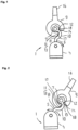
- a rope holder 1 according to the invention is shown interacting with a running element 9 according to the invention.
- the rope holder 1 for fall protection has a console 4 for a functionally reliable arrangement on a structure and a rope holder 5 .
- the cable holder 5 and the console 4 are connected to each other.
- the cable holder 5 is mounted on the console 4 so that it can be rotated in a reversible manner.
- the axis of rotation 2 of the cable holder 4 or the cable holder 5 is parallel to a cable 3, as in Fig. 3 shown, relocated.
- the cable holder and/or the console 4 has a spring element 6 .
- the cable holder 5 has a cable guide 7 and a web 8 , the cable guide 7 adjoining the web 8 , as shown in the figures.
- the web 8 has an arc section 10 in a contact area with a running element 9 existing as a separate component, which is displaced parallel in the cable direction.
- the curved section 10 of the web 8 points in the direction of rotation of the cable holder 1 in relation to an initial position of the cable holder 1. The initial position is in Fig. 1 shown.
- the arch section 10 is raised in the direction of rotation, which ensures a spring effect of the web 8 and thus of the cable holder 5 - even if this is generally lower in relation to a rotatable bearing.
- a spring effect can be provided.
- the curved section 10 of the web 8 forms a groove 11 as a first guide 13 for the running element 9, so that it can slide over the cable holder 1 as smoothly as possible.
- the cable guide 7 points in the direction of rotation of the cable holder 1, more precisely its cable holder 5 , based on the known starting position Fig. 1 -
- an elevation which is designed as a cam 12 in the exemplary embodiment.
- a second guide 14 is thus formed together with the curved section 10 of the web 8 , which further supports the largely smooth sliding of the running element 9 over the cable holder 1 .
- the first guide 13 and the second guide 14 are shaped differently in relation to their cross section.
- the running element 9 arranged or arranged on the cable holder 1 has a longitudinal slot 15 running parallel to the cable 3 of the cable holder 1 on, Fig. 3 .
- the longitudinal slot 15 is located in a defined angular position in relation to a receptacle 16 for a known carabiner of a height safety device at approximately 125 °.
- the running element 9 has a first longitudinal slot edge 17 and a further longitudinal slot edge 18 .
- the first longitudinal slot edge 17 is designed to correspond in shape to the first guide 13 of the rope holder 1 and the second longitudinal slot edge 18 is designed to correspond in shape to the second guide 14 of the rope holder 1 . Because of the different shape of the first guide 13 and the second guide 14, the first longitudinal slot edge 17 and a further longitudinal slot edge 18 also have a different design.
- first longitudinal slot edge 17 interacts with the first guide 13 and the second longitudinal slot edge 18 with the second guide 14 in a slight clearance fit when the running element 9 rests on the cable holder 1 , so when the cable holder 1 slides over and thus also it Cable guide 7 through the running element 9.
- This design of the components ensures that, as already explained, a positive connection of the running element 9 with the cable holder 1 with a clearance fit is ensured when the running element 9 rests on the cable holder 1 .
- the positive fit prevents or minimizes tilting. If tensile forces then emanate from a rope 3 of a height safety device located on the receptacle 16 in the direction of rotation of the rope receptacle 1 , then this leads to the rotation of the rope receptacle 5 and if the reversible rotation is limited by the design at a stop or otherwise, then by the design of the spring element 6 is, to the fact that the described spring action of the arch section 10 or the web 8 can have an additional effect after reaching such a stop. This reduces the risk of the running element 9 tilting at an angle to its running direction. This creates a reversibly movable, rotatable guide, which transferring the running element 9 over the cable holder 1 is simplified.
Landscapes
- Architecture (AREA)
- Engineering & Computer Science (AREA)
- General Health & Medical Sciences (AREA)
- Emergency Management (AREA)
- Business, Economics & Management (AREA)
- Health & Medical Sciences (AREA)
- Civil Engineering (AREA)
- Structural Engineering (AREA)
- Mechanical Engineering (AREA)
- Electric Cable Arrangement Between Relatively Moving Parts (AREA)
- Guides For Winding Or Rewinding, Or Guides For Filamentary Materials (AREA)
- Emergency Lowering Means (AREA)
- Cable Accessories (AREA)
Description
- Die Erfindung betrifft eine Seilhalterung sowie ein Laufelement für ein Seilsystem einer Absturzsicherung.
- Bei bekannten Absturzsicherungen mit im Wesentlichen horizontal angeordneten Seilen besteht die Gefahr des Verkantens eines Laufelements mit einer Seilhalterung, wenn das Laufelement über eine Seilhalterung geführt wird. Das ist auch dann der Fall, wenn das Laufelement, welches regelmäßig eine schlitzartige Öffnung, ein so genannter Längsschlitz, parallel verlaufend zu einem Seil der Seilhalterung aufweist, in einer Winkellage angeordnet ist, welche in Bezug zu einer Aufnahme für einen Karabiner oder Ähnlichem zwischen 90° und 180° gelegen ist. Diese Betrachtung der Winkellage erfolgt bei einem Querschnitt im rechten Winkel zur Längsachse des Laufelements.
- Solche Seilhalterungen ohne spezifische Führung sind beispielhaft aus der
EP 0 273 673 A1 und derEP 2 269 696 A1 bekannt.EP 2 269 696 offenbart eine Seilhalterung und ein Laufelement gemäß dem Oberbegriff der Ansprüche 1 und 2. - Zudem hat sich herausgestellt, dass bei einer solchen Winkellage des Längsschlitzes die Seilhalterung nicht mit einem lotrecht verlaufenden Steg montiert werden kann, sondern stets in der entsprechenden Winkellage, wenn die Aufnahme des Laufelements selbst vertikal gehalten werden soll. Dies ist konstruktionsbedingt jedoch nachteilig.
- Wirkt auf das Laufelement bei einem Überführen desselben über die Seilhalterung eine Kraft in Drehrichtung des Laufelements auf dem Seil, wirken auf die Seilhalterung, so auf den Steg, Biegekräfte, welche zu einer Verformung der Seilhalterung, insbesondere des Steges der Seilhalterung führen können.
- Die Aufgabe der Erfindung besteht demgemäß darin, ein Laufelement sowie eine Seilhalterung für eine Absturzsicherung zur Verfügung zu stellen, bei welcher ein Verkanten der Seilhalterung mit dem Laufelement vermindert wird und die Gefahr einer Verformung der Seilhalterung durch auf diese einwirkende Biegekräfte verringert wird.
- Die Aufgabe wird erfindungsgemäß durch die Merkmale der Ansprüche 1 und 2 verwirklicht. Die Seilhalterung gemäß einer Ausführungsform ist für eine Absturzsicherung reversibel drehbar gelagert und die Drehachse der Seilhalterung ist parallel verschoben zu einem Seil gelegen.
- Die Seilhalterung weist in weiterer Ausgestaltung eine Konsole zur funktionssicheren, form- und/oder kraftschlüssigen Anordnung an einen Baukörper und eine Seilaufnahme auf. Die Seilaufnahme und die Konsole sind dabei miteinander verbunden. Die Seilaufnahme ist an der Konsole reversibel drehbar gelagert. Die Drehachse der Seilaufnahme ist parallel zu einem Seil beziehungsweise dessen Halterung verschoben gelegen. Dabei wird von dem Fall ausgegangen, dass das Seil keine Abknickung aufweist.
- Zur Gewährung der Reversibilität weist die Seilaufnahme und/oder die Konsole mindestens ein Federelement auf. Erfindungsgemäß kann jedes bekannte Federelement zum Einsatz kommen, was konstruktiv geeignet ist.
- In weiterer Ausgestaltung weist die Seilaufnahme eine Seilführung und einen Steg auf, wobei sich die Seilführung an den Steg, an seinem der Konsole abgewandten freien Ende, anschließt. Der Steg weist, beispielhaft parallel verschoben in Seilrichtung, einen Bogenabschnitt auf, der sich an der Seilführung anschließt und in Richtung der Konsole erstreckt.
- Der Bogenabschnitt schließt sich dabei in der Regel an einem Kontaktbereich des Stegs mit einem Laufelement an, wenn das Laufelement an der Seilführung funktionsgemäß anliegt.
- Er kann beispielsweise eine Sicke oder eine bogenförmige Ausformung sein. Parallel verschoben in Seilrichtung bedeutet, das eine Langseite oder Achse eines Querschnitts des Stegs mit seinem Bogenabschnitt parallel oder wesentlich parallel verschoben zum Seil verläuft. Vorzugsweise ist der Steg und damit auch der Bogenabschnitt in einem rechten Winkel zur Seilführung an dieser angeordnet.
- Der Bogenabschnitt des Stegs weist in Drehrichtung der Seilhalterung, bezogen auf eine Ausgangslage, welche die Seilhalterung ohne Krafteinwirkung einnimmt. Er ist in Drehrichtung, der Richtung, in welche das Federelement gespannt wird, erhaben, wodurch eine besonders effektive Federwirkung der Seilaufnahme gewährleistet wird. Durch den Bogenabschnitt besitzt der Steg eine Federwirkung und kann somit zusätzlich zur reversiblen drehbaren Lagerung eine Federwirkung gewähren.
- Die erfindungsgemäße Seilhalterung umfasst eine Seilführung und die Seilführung besitzt nur einen Steg, wobei die Seilführung an den Steg wie erläutert anschließt und der Steg in einem Kontaktbereich mit einem Laufelement parallel verschoben in Seilrichtung den vorbeschriebenen Bogenabschnitt aufweist. Dieser gewährt sodann allein eine Federwirkung des Stegs und damit der Seilhalterung.
- Im Rahmen der Erfindung ist vorgesehen, dass der Bogenabschnitt des Stegs eine Hohlkehle als erste Führung für ein Laufelement bildet, damit dieses weitestgehend ruckfrei die Seilhalterung übergleiten kann.
- Dabei ist erfindungsgemäß vorgesehen, dass die Seilführung - in Drehrichtung der Seilhalterung bezogen auf eine Ausgangslage - an einem Übergang zu dem Steg mit seinem Bogenabschnitt und gegenüberliegend zur Hohlkehle eine Erhebung, so eine Nocke, aufweist. So wird mit dem Bogenabschnitt des Stegs zusammen eine zweite Führung gebildet, welche das weitestgehend ruckfreie Übergleiten des Laufelements über die Seilhalterung weiter unterstützt. Als gegenüberliegend ist dabei zu verstehen, dass die Erhebung an einer zur Hohlkehle gegenüberliegenden Fläche des Bogenabschnitts gelegen ist.
- Ebenfalls ist erfindungsgemäß vorgesehen, dass die erste Führung und die zweite Führung in Bezug auf ihren Querschnitt unterschiedlich geformt sind. Dies gewährleistet, dass ein Laufelement stets nur in einer vorbestimmten Anordnung über die Seilführung überführt werden kann. Das dient dazu, zu verhindern, dass bei einer etwaigen verkehrten Einführung des Laufelements auf das Seil eine für die Vorrichtung atypische Winkellage bei einem Überführen über die Seilhalterung herzustellen ist, bei welcher zum Beispiel eine andere Hebelwirkung erzeugt wird, wenn an dem Laufelement bei dem Überführen über die Seilhalterung radial zum Seil Zugkräfte wirken. Auch kann die Lage bei einem etwaig verkehrten Überführen so ungünstig sein, dass ein Überführen des Laufelements über die Seilhalterung für eine zu sichernde Person mit hohem Aufwand verbunden ist, weil das Laufelement für das Überführen erst in eine dafür untypische Lage zu bringen ist. Dies soll mit der Lösung verhindert werden.
- Des Weiteren kann zur Optimierung eines Übergleitens vorgesehen werden, dass die Stirnseiten der Seilaufnahme, insbesondere der Seilhalterung, eine im Verhältnis zum Verlauf des Seils spitzwinklige Lage aufweisen, also abgeschrägte Flächen sind. Das trifft auch für den Steg zu.
- Weiterhin wird die Aufgabe durch ein Laufelement für eine Absturzsicherung mit einer Seilhalterung mit einer ersten und einer zweiten Führung ausgestattet - gelöst, wobei das Laufelement, wie bekannt, einen Längsschlitz im funktionsgemäß an einem Seil angeordneten Zustand parallel zu einem Seil der Seilhalterung verlaufend aufweist. Dabei ist der Längsschlitz an einer Langseite des Laufelements belegen und in einer definierten Winkellage in Bezug zu einer Aufnahme für einen Karabiner oder Ähnlichem zwischen 90° und 180°, vorteilhafterweise bei 112° gelegen. Dabei weist das Laufelement eine erste und eine weitere Längsschlitzkante auf. Die erste Längsschlitzkante ist ihrer Form nach mit der ersten Führung der Seilhalterung und die zweite Längsschlitzkante ihrer Form nach mit der zweiten Führung der Seilhalterung korrespondierend gestaltet. Diese Betrachtung erfolgt in Bezug auf den Querschnitt im rechten Winkel zur Längsachse des Laufelements. Dabei ist ferner vorgesehen, dass die erste Längsschlitzkante mit der ersten Führung und die zweite Längsschlitzkante mit der zweiten Führung in Spielpassung, vorteilhafterweise in leichter Spielpassung, zusammenwirken, wenn das Laufelement an der Seilhalterung, also der Seilführung anliegt, so bei einem Übergleiten der Seilführung durch das Laufelement. Unter Spielpassung im Sinne der Erfindung ist eine solche Passung zu verstehen, bei der ein leichtes Übergleiten sichergestellt ist und ein Verkanten des Laufelements ausscheidet. Insofern besteht je nach konkreter Gestaltung von Seilhalterung und ihrer Seilführung sowie dem Laufelement ein gewisser konstruktiver Gestaltungsspielraum.
- Die vorbeschriebene korrespondierende Gestaltung bewirkt, wenn das Laufelement auf der Seilführung gelegen ist, dass dadurch ein Formschluss mit Spielpassung des Laufelementes mit der Seilführung bei axialer Drehung, also bei Drehung auf dem Seil gelagert und die Achse des Seils, sichergestellt ist. Dies führt dazu, dass die vorbeschriebene Federwirkung des Bogenabschnitts bzw. des Stegs seine Wirkung voll entfalten kann, zusätzlich neben der drehbar gelagerten Seilhalterung beziehungsweise Seilaufnahme. Dies gewährt eine Minimierung eines Verkantens winklig zur Laufrichtung des Laufelements aufgrund der so geschaffenen Führung und ihrer reversiblen drehbaren Anordnung.
- In weiterer Ausgestaltung weisen Stirnseiten des Laufelements eine im Verhältnis zum Verlauf des Seils spitzwinklige Lage auf. Es handelt sich dabei um abgeschrägte Flächen, was eine einfache und ruckfreie Ausrichtung des Laufelements mit der Seilaufnahme bei einem Überführen des Laufelements über die Seilhalterung gewährt.
- Die Erfindung wird nachfolgend anhand eines Ausführungsbeispiels unter Bezugnahme auf die Figuren weiter erläutert. Dabei ergeben sich weitere Vorteile, Merkmale und Ausgestaltungen der Erfindung.
- Es zeigen:
-
Fig. 1 und Fig. 2 eine erfindungsgemäße Seilhalterung mit angeordnetem Laufelement, -
Fig. 3 eine erfindungsgemäße Seilhalterung mit angeordnetem Laufelement in Schrägperspektive mit Seil. - In den
Fig. 1 bis 3 ist eine erfindungsgemäße Seilhalterung 1 mit erfindungsgemäßem Laufelement 9 zusammenwirkend dargestellt. - Im Ausführungsbeispiel weist die Seilhalterung 1 für eine Absturzsicherung eine Konsole 4 zur funktionssicheren Anordnung an einen Baukörper und eine Seilaufnahme 5 auf.
- Die Seilaufnahme 5 und die Konsole 4 sind dabei miteinander verbunden. Die Seilaufnahme 5 ist an der Konsole 4 reversibel drehbar gelagert. Die Drehachse 2 der Seilhalterung 4 bzw. der Seilaufnahme 5 ist parallel zu einem Seil 3, wie in
Fig. 3 dargestellt, verschoben gelegen. Zur Gewährung der Reversibilität weist die Seilaufnahme und/oder die Konsole 4 ein Federelement 6 auf. - Ferner weist die Seilaufnahme 5 eine Seilführung 7 und einen Steg 8 auf, wobei sich die Seilführung 7 an dem Steg 8 anschließt, wie in den Figuren dargestellt. Der Steg 8 weist in einem Kontaktbereich mit einem als separatem Bauteil bestehenden Laufelement 9 parallel verschoben in Seilrichtung einen Bogenabschnitt 10 auf. Der Bogenabschnitt 10 des Steges 8 weist in Drehrichtung der Seilhalterung 1 bezogen auf eine Ausgangslage der Seilhalterung 1. Die Ausgangslage ist in
Fig. 1 dargestellt. Der Bogenabschnitt 10 ist in Drehrichtung erhaben, wodurch eine Federwirkung des Stegs 8 und damit der Seilaufnahme 5 - auch wenn diese grundsätzlich in Bezug zu einer drehbaren Lagerung geringer ist - gewährleistet wird. Somit kann zusätzlich zur reversiblen drehbaren Lagerung der Seilaufnahme 5 eine Federwirkung dieser gewährt werden. - Des Weiteren bildet der Bogenabschnitt 10 des Stegs 8 eine Hohlkehle 11 als erste Führung 13 für das Laufelement 9, damit dieses weitestgehend ruckfrei die Seilhalterung 1 übergleiten kann.
- Ferner weist die Seilführung 7 - in Drehrichtung der Seilhalterung 1, genauer gesagt ihrer Seilaufnahme 5 bezogen auf die bekannte Ausgangslage gemäß
Fig. 1 - an einem Übergang zum Steg 8 mit seinem Bogenabschnitt 10 und im gegenüberliegend zu der Hohlkehle 11 eine Erhebung auf, welche im Ausführungsbeispiel als Nocke 12 ausgestaltet ist. So wird mit dem Bogenabschnitt 10 des Stegs 8 zusammen eine zweite Führung 14 gebildet, welche das weitestgehend ruckfreie Übergleiten des Laufelements 9 über die Seilhalterung 1 weiter unterstützt. - Die erste Führung 13 und die zweite Führung 14 sind dabei in Bezug auf ihren Querschnitt unterschiedlich geformt.
- Das an der Seilhalterung 1 angeordnete beziehungsweise anordenbare Laufelement 9 weist im Ausführungsbeispiel, wie bekannt, einen Längsschlitz 15 parallel zu dem Seil 3 der Seilhalterung 1 verlaufend auf,
Fig. 3 . Dabei ist der Längsschlitz 15 in einer definierten Winkellage in Bezug zu einer Aufnahme 16 für einen bekannten Karabiner einer Höhensicherung bei ca. 125° gelegen. Das Laufelement 9 weist eine erste Längsschlitzkante 17 und eine weitere Längsschlitzkante 18 auf. Die erste Längsschlitzkante 17 ist ihrer Form nach mit der ersten Führung 13 der Seilhalterung 1 und die zweite Längsschlitzkante 18 ihrer Form nach mit der zweiten Führung 14 der Seilhalterung 1 korrespondierend gestaltet. Wegen der unterschiedlichen Form der ersten Führung 13 und der zweiten Führung 14 weisen die erste Längsschlitzkante 17 und eine weitere Längsschlitzkante 18 ebenfalls eine unterschiedliche Gestaltung auf. - Dabei ist vorgesehen, dass die erste Längsschlitzkante 17 mit der ersten Führung 13 und die zweite Längsschlitzkante 18 mit der zweiten Führung 14 in leichter Spielpassung zusammenwirken, wenn das Laufelement 9 an der Seilhalterung 1 anliegt, so bei einem Übergleiten der Seilhalterung 1 und damit auch ihrer Seilführung 7 durch das Laufelement 9.
- Diese der Formgebung nach korrespondierende Gestaltung der Bauteile bewirkt, dass wie schon erläutert, ein Formschluss des Laufelements 9 mit der Seilhalterung 1 mit Spielpassung sichergestellt ist, wenn das Laufelement 9 an der Seilhalterung 1 anliegt. Der Formschluss verhindert bzw. minimiert ein Verkanten. Wenn sodann Zugkräfte von einem an der Aufnahme 16 gelegenen Seil 3 einer Höhensicherung in Drehrichtung der Seilaufnahme 1 ausgehen, dann führt dies zur Drehung der Seilaufnahme 5 und wenn die reversible Drehung gestaltungsbedingt an einem Anschlag oder sonstig, so durch die Gestaltung des Federelements 6, begrenzt ist, dazu, dass die beschriebene Federwirkung des Bogenabschnitts 10 bzw. des Stegs 8 nach Erreichen eines solchen Anschlags zusätzlich Wirkung entfalten kann. Dies gewährt eine Reduzierung der Gefahr eines Verkantens des Laufelements 9 winklig zu seiner Laufrichtung. Es wird so eine reversibel bewegliche, drehbare Führung geschaffen, welche ein Überführen des Laufelements 9 über die Seilhalterung 1 vereinfacht.
-
- 1.
- Seilhalterung
- 2.
- Drehachse
- 3.
- Seil
- 4.
- Konsole
- 5.
- Seilaufnahme
- 6.
- Federelement
- 7.
- Seilführung
- 8.
- Steg
- 9.
- Laufelement
- 10.
- Bogenabschnitt
- 11.
- Hohlkehle
- 12.
- Nocke
- 13.
- erste Führung
- 14.
- zweite Führung
- 15.
- Längsschlitz
- 16.
- Aufnahme
- 17.
- erste Längsschlitzkante
- 18.
- weitere Längsschlitzkante
Claims (2)
- Seilhalterung (1) für eine Absturzsicherung, mit einer Seilführung (7) und einem Steg (8), wobei die Seilführung (7) an den Steg (8) anschließt und der Steg (8) einen Bogenabschnitt (10) aufweist, der sich an der Seilführung (7) anschließt und in Richtung einer Konsole (4) erstreckt, der Bogenabschnitt (10) des Stegs (8) eine Hohlkehle (11) als eine erste Führung (13) bildet,
dadurch gekennzeichnet, dass die Seilführung (7) an einem Übergang zu dem Steg (8) mit seinem Bogenabschnitt (10) und gegenüberliegend zu der Hohlkehle (11) eine Erhebung aufweist, wodurch mit dem Bogenabschnitt (10) des Stegs (8) zusammen die zweite Führung (14) gebildet wird und die erste Führung (13) und die zweite Führung (14) in Bezug auf ihren Querschnitt unterschiedlich geformt sind. - Laufelement (9) für eine Absturzsicherung mit einer Seilhalterung (1) mit einer ersten Führung (13) und einer zweiten Führung (14) nach Anspruch 1, wobei das Laufelement (9) eine Aufnahme (16)für einen Karabiner oder Ähnlichem und einen Längsschlitz (15) im funktionsgemäß an einem Seil (3) angeordneten Zustand parallel zu dem Seil (3) der Seilhalterung (1) verlaufend aufweist, der Längsschlitz (15) in einer Winkellage in Bezug zu der Aufnahme (16) zwischen 90° und 180°, vorteilhafterweise bei 112° gelegen ist, und einer ersten und einer weiteren Längsschlitzkante (17), (18) aufweist, dadurch gekennzeichnet, dass und die erste Längsschlitzkante (17) ihrer Form nach mit der ersten Führung (13) der Seilhalterung (1) und die weitere Längsschlitzkante (18) ihrer Form nach mit der zweiten Führung (14) der Seilhalterung (1) korrespondierend gestaltet sind und dass die erste Längsschlitzkante (17) mit der ersten Führung (13) und die weitere Längsschlitzkante (18) mit der zweiten Führung (14) in Spielpassung zusammenwirken, wenn das Laufelement (9) an der Seilführung (7) der Seilhalterung (1) anliegt.
Applications Claiming Priority (2)
| Application Number | Priority Date | Filing Date | Title |
|---|---|---|---|
| DE102017004948.3A DE102017004948A1 (de) | 2017-05-23 | 2017-05-23 | Seilhalterung und Laufelement |
| PCT/IB2018/000809 WO2018215842A1 (de) | 2017-05-23 | 2018-05-18 | Seilhalterung und laufelement |
Publications (3)
| Publication Number | Publication Date |
|---|---|
| EP3631120A1 EP3631120A1 (de) | 2020-04-08 |
| EP3631120B1 true EP3631120B1 (de) | 2024-03-20 |
| EP3631120C0 EP3631120C0 (de) | 2024-03-20 |
Family
ID=63350574
Family Applications (1)
| Application Number | Title | Priority Date | Filing Date |
|---|---|---|---|
| EP18759168.0A Active EP3631120B1 (de) | 2017-05-23 | 2018-05-18 | Seilhalterung und laufelement |
Country Status (6)
| Country | Link |
|---|---|
| US (1) | US11583711B2 (de) |
| EP (1) | EP3631120B1 (de) |
| AU (1) | AU2018273077B2 (de) |
| DE (1) | DE102017004948A1 (de) |
| ES (1) | ES2979318T3 (de) |
| WO (1) | WO2018215842A1 (de) |
Families Citing this family (3)
| Publication number | Priority date | Publication date | Assignee | Title |
|---|---|---|---|---|
| DE102017004948A1 (de) * | 2017-05-23 | 2018-11-29 | Spanset Inter Ag | Seilhalterung und Laufelement |
| US11833376B2 (en) * | 2019-11-01 | 2023-12-05 | Honeywell International Inc. | Horizontal lifeline shuttle apparatus |
| USD1049386S1 (en) | 2023-07-31 | 2024-10-29 | Spanset Inter Ag | Cable holder for fall protection devices |
Family Cites Families (22)
| Publication number | Priority date | Publication date | Assignee | Title |
|---|---|---|---|---|
| GB8630787D0 (en) | 1986-12-23 | 1987-02-04 | Barrow Hepburn Equip Ltd | Fall-arrest cable attachments |
| GB9110900D0 (en) * | 1991-05-21 | 1991-07-10 | Barrow Hepburn Sala Ltd | Safety apparatus |
| US5979599A (en) * | 1996-12-17 | 1999-11-09 | Noles; Larry J. | Track transport system, track-support bracket, and track-traveling apparatus |
| US6056085A (en) * | 1998-10-23 | 2000-05-02 | Capital Safety Inc. | Anchorage methods and apparatus |
| FR2804708B1 (fr) * | 2000-02-03 | 2002-03-15 | Dalloz Fall Prot | Dispositif de fixation d'une ligne de vie contre une paroi |
| FR2813800B1 (fr) * | 2000-09-13 | 2002-10-11 | Dalloz Fall Prot | Coulisseau pour ligne de vie |
| GB2395976A (en) * | 2002-12-06 | 2004-06-09 | Latchways Plc | Safety line traveller and support |
| GB0328937D0 (en) * | 2003-12-13 | 2004-01-14 | Checkmate Uk Ltd | Lifeline trolley |
| DE202005006743U1 (de) * | 2005-04-27 | 2005-06-30 | Eduard Kaufmann Gmbh | Läufer für eine Anschlageinrichtung |
| US7458443B2 (en) * | 2006-05-09 | 2008-12-02 | Raymond Givonetti | Pedal actuated bicycle brake system |
| DK178145B1 (da) * | 2008-03-05 | 2015-06-29 | Aip Aps | System til begrænsning af horisontale bevægelser i en lift |
| DE202008004254U1 (de) * | 2008-03-28 | 2009-08-13 | Sperian Fall Protection Deutschland Gmbh & Co. Kg | Zwischenhalter für das Sicherungsseil eines Überkopf-Seilsystems einer Absturzsicherung |
| GB2463631A (en) | 2008-04-28 | 2010-03-24 | Latchways Plc | Safety line traveller and support |
| CH700884A2 (de) * | 2009-04-22 | 2010-10-29 | Repapress Ag | Sicherheitseinrichtung für einen Seilgarten. |
| CH702713B1 (fr) * | 2010-02-19 | 2014-09-15 | Speedrunner Gmbh | Système de ligne d'assurage continue. |
| FR2962658B1 (fr) * | 2010-07-16 | 2012-07-13 | Tractel Sas | Systeme de ligne de vie pour protection antichute, coulisseau, support de cable et manchon |
| US9364695B2 (en) * | 2011-10-20 | 2016-06-14 | Prochute Securite Inc. | Trolley comprising a fall arrest actuator |
| AU2016314035B2 (en) * | 2015-08-28 | 2021-03-11 | Safetylink Pty Ltd | Shuttle device |
| US20180154197A1 (en) * | 2016-12-04 | 2018-06-07 | Alexander Andrew, Inc. Dba Falltech | Horizontal lifelines with safety improvements |
| DE102017004948A1 (de) * | 2017-05-23 | 2018-11-29 | Spanset Inter Ag | Seilhalterung und Laufelement |
| US10619417B2 (en) * | 2018-03-08 | 2020-04-14 | Meyer Ostrobrod | Pass-through cable grab system |
| GB2582587B (en) * | 2019-03-26 | 2023-01-04 | Latchways Plc | Safety line apparatus |
-
2017
- 2017-05-23 DE DE102017004948.3A patent/DE102017004948A1/de not_active Withdrawn
-
2018
- 2018-05-18 WO PCT/IB2018/000809 patent/WO2018215842A1/de not_active Ceased
- 2018-05-18 EP EP18759168.0A patent/EP3631120B1/de active Active
- 2018-05-18 US US16/615,515 patent/US11583711B2/en active Active
- 2018-05-18 AU AU2018273077A patent/AU2018273077B2/en active Active
- 2018-05-18 ES ES18759168T patent/ES2979318T3/es active Active
Also Published As
| Publication number | Publication date |
|---|---|
| AU2018273077B2 (en) | 2024-06-06 |
| ES2979318T3 (es) | 2024-09-25 |
| DE102017004948A1 (de) | 2018-11-29 |
| WO2018215842A1 (de) | 2018-11-29 |
| BR112019024384A2 (pt) | 2020-06-09 |
| AU2018273077A1 (en) | 2019-12-19 |
| US11583711B2 (en) | 2023-02-21 |
| EP3631120A1 (de) | 2020-04-08 |
| EP3631120C0 (de) | 2024-03-20 |
| US20200114183A1 (en) | 2020-04-16 |
Similar Documents
| Publication | Publication Date | Title |
|---|---|---|
| EP2614203B1 (de) | Seilumlenkstück für einen seilfensterheber | |
| DE102014206825A1 (de) | Scharniereinrichtung für eine KFZ- Tür | |
| WO2014026864A1 (de) | Katheterkupplung | |
| DE102015122575A1 (de) | Sicherheitsvorrichtung für ein Kraftfahrzeug mit einer Drehfalle und einer Vorraststellung und einer Hauptraststellung | |
| EP3286440B2 (de) | Vorrichtung zum festlegen an einem bauteil | |
| DE102013202792B4 (de) | Verbindungsanordnung zwischen einem radführenden Lenker einer Fahrzeug-Radaufhängung und einem Flansch | |
| WO2020160879A1 (de) | Anschlussklemme sowie anschlussklemmenblock | |
| EP3394372A1 (de) | Sicherheitsvorrichtung für ein kraftfahrzeug mit einer drehfalle und einer auswurffeder | |
| DE102004015825B4 (de) | Gurtaufroller für einen Fahrzeug-Sicherheitsgurt | |
| EP3631120A1 (de) | Seilhalterung und laufelement | |
| DE102009035874A1 (de) | Vorrichtung zur Verbindung zweier Bauteile miteinander | |
| DE2529910A1 (de) | Rueckschlagklappe | |
| EP3757435B1 (de) | Halterung für langgestreckte gegenstände | |
| EP3747183B1 (de) | Universielle halterung für ein telekommunikations-endgerät | |
| CH705939A1 (de) | Fangvorrichtung für eine Steigschutzeinrichtung. | |
| EP3323476B1 (de) | Tourenbindung zur montage an einem gleitbrett | |
| EP3882688B1 (de) | Federscharnier für eine brille | |
| DE102006037544B4 (de) | Gurtaufroller und Verfahren zum Betreiben eines solchen Gurtaufrollers | |
| EP3917804B1 (de) | Sichteinstellmechanismus | |
| DE102015223161A1 (de) | Anschlagpunkt mit beweglicher Kippachse | |
| DE102010000924A1 (de) | Handhabe für eine Schließeinrichtung eines Kraftfahrzeuges | |
| DE102015111300B4 (de) | Fahrzeugschiebedach | |
| EP3741954A1 (de) | Vorrichtung zur lösbaren verbindung einer wickelwelle eines rollladenpanzers mit einer hochschiebesicherung | |
| DE102008006011B4 (de) | Befestigungsmittel für die Befestigung eines Kühlwasserausgleichsbehälters eines Kraftfahrzeugs | |
| WO2005037616A1 (de) | Selbstsperrender gurtaufroller |
Legal Events
| Date | Code | Title | Description |
|---|---|---|---|
| STAA | Information on the status of an ep patent application or granted ep patent |
Free format text: STATUS: UNKNOWN |
|
| STAA | Information on the status of an ep patent application or granted ep patent |
Free format text: STATUS: THE INTERNATIONAL PUBLICATION HAS BEEN MADE |
|
| PUAI | Public reference made under article 153(3) epc to a published international application that has entered the european phase |
Free format text: ORIGINAL CODE: 0009012 |
|
| STAA | Information on the status of an ep patent application or granted ep patent |
Free format text: STATUS: REQUEST FOR EXAMINATION WAS MADE |
|
| 17P | Request for examination filed |
Effective date: 20191218 |
|
| AK | Designated contracting states |
Kind code of ref document: A1 Designated state(s): AL AT BE BG CH CY CZ DE DK EE ES FI FR GB GR HR HU IE IS IT LI LT LU LV MC MK MT NL NO PL PT RO RS SE SI SK SM TR |
|
| AX | Request for extension of the european patent |
Extension state: BA ME |
|
| DAV | Request for validation of the european patent (deleted) | ||
| DAX | Request for extension of the european patent (deleted) | ||
| STAA | Information on the status of an ep patent application or granted ep patent |
Free format text: STATUS: EXAMINATION IS IN PROGRESS |
|
| 17Q | First examination report despatched |
Effective date: 20210304 |
|
| GRAP | Despatch of communication of intention to grant a patent |
Free format text: ORIGINAL CODE: EPIDOSNIGR1 |
|
| STAA | Information on the status of an ep patent application or granted ep patent |
Free format text: STATUS: GRANT OF PATENT IS INTENDED |
|
| INTG | Intention to grant announced |
Effective date: 20230424 |
|
| GRAJ | Information related to disapproval of communication of intention to grant by the applicant or resumption of examination proceedings by the epo deleted |
Free format text: ORIGINAL CODE: EPIDOSDIGR1 |
|
| STAA | Information on the status of an ep patent application or granted ep patent |
Free format text: STATUS: EXAMINATION IS IN PROGRESS |
|
| GRAP | Despatch of communication of intention to grant a patent |
Free format text: ORIGINAL CODE: EPIDOSNIGR1 |
|
| STAA | Information on the status of an ep patent application or granted ep patent |
Free format text: STATUS: GRANT OF PATENT IS INTENDED |
|
| INTC | Intention to grant announced (deleted) | ||
| RIN1 | Information on inventor provided before grant (corrected) |
Inventor name: EHNIMB, DAVID Inventor name: MAMIE, ANDRE |
|
| GRAJ | Information related to disapproval of communication of intention to grant by the applicant or resumption of examination proceedings by the epo deleted |
Free format text: ORIGINAL CODE: EPIDOSDIGR1 |
|
| STAA | Information on the status of an ep patent application or granted ep patent |
Free format text: STATUS: EXAMINATION IS IN PROGRESS |
|
| INTG | Intention to grant announced |
Effective date: 20230905 |
|
| GRAP | Despatch of communication of intention to grant a patent |
Free format text: ORIGINAL CODE: EPIDOSNIGR1 |
|
| STAA | Information on the status of an ep patent application or granted ep patent |
Free format text: STATUS: GRANT OF PATENT IS INTENDED |
|
| INTC | Intention to grant announced (deleted) | ||
| INTG | Intention to grant announced |
Effective date: 20231011 |
|
| GRAS | Grant fee paid |
Free format text: ORIGINAL CODE: EPIDOSNIGR3 |
|
| GRAA | (expected) grant |
Free format text: ORIGINAL CODE: 0009210 |
|
| STAA | Information on the status of an ep patent application or granted ep patent |
Free format text: STATUS: THE PATENT HAS BEEN GRANTED |
|
| AK | Designated contracting states |
Kind code of ref document: B1 Designated state(s): AL AT BE BG CH CY CZ DE DK EE ES FI FR GB GR HR HU IE IS IT LI LT LU LV MC MK MT NL NO PL PT RO RS SE SI SK SM TR |
|
| REG | Reference to a national code |
Ref country code: GB Ref legal event code: FG4D Free format text: NOT ENGLISH |
|
| REG | Reference to a national code |
Ref country code: CH Ref legal event code: EP |
|
| REG | Reference to a national code |
Ref country code: DE Ref legal event code: R096 Ref document number: 502018014292 Country of ref document: DE |
|
| REG | Reference to a national code |
Ref country code: IE Ref legal event code: FG4D Free format text: LANGUAGE OF EP DOCUMENT: GERMAN |
|
| U01 | Request for unitary effect filed |
Effective date: 20240418 |
|
| U07 | Unitary effect registered |
Designated state(s): AT BE BG DE DK EE FI FR IT LT LU LV MT NL PT SE SI Effective date: 20240425 |
|
| U20 | Renewal fee for the european patent with unitary effect paid |
Year of fee payment: 7 Effective date: 20240515 |
|
| PG25 | Lapsed in a contracting state [announced via postgrant information from national office to epo] |
Ref country code: GR Free format text: LAPSE BECAUSE OF FAILURE TO SUBMIT A TRANSLATION OF THE DESCRIPTION OR TO PAY THE FEE WITHIN THE PRESCRIBED TIME-LIMIT Effective date: 20240621 |
|
| PG25 | Lapsed in a contracting state [announced via postgrant information from national office to epo] |
Ref country code: RS Free format text: LAPSE BECAUSE OF FAILURE TO SUBMIT A TRANSLATION OF THE DESCRIPTION OR TO PAY THE FEE WITHIN THE PRESCRIBED TIME-LIMIT Effective date: 20240620 Ref country code: HR Free format text: LAPSE BECAUSE OF FAILURE TO SUBMIT A TRANSLATION OF THE DESCRIPTION OR TO PAY THE FEE WITHIN THE PRESCRIBED TIME-LIMIT Effective date: 20240320 |
|
| PG25 | Lapsed in a contracting state [announced via postgrant information from national office to epo] |
Ref country code: RS Free format text: LAPSE BECAUSE OF FAILURE TO SUBMIT A TRANSLATION OF THE DESCRIPTION OR TO PAY THE FEE WITHIN THE PRESCRIBED TIME-LIMIT Effective date: 20240620 Ref country code: NO Free format text: LAPSE BECAUSE OF FAILURE TO SUBMIT A TRANSLATION OF THE DESCRIPTION OR TO PAY THE FEE WITHIN THE PRESCRIBED TIME-LIMIT Effective date: 20240620 Ref country code: HR Free format text: LAPSE BECAUSE OF FAILURE TO SUBMIT A TRANSLATION OF THE DESCRIPTION OR TO PAY THE FEE WITHIN THE PRESCRIBED TIME-LIMIT Effective date: 20240320 Ref country code: GR Free format text: LAPSE BECAUSE OF FAILURE TO SUBMIT A TRANSLATION OF THE DESCRIPTION OR TO PAY THE FEE WITHIN THE PRESCRIBED TIME-LIMIT Effective date: 20240621 |
|
| REG | Reference to a national code |
Ref country code: ES Ref legal event code: FG2A Ref document number: 2979318 Country of ref document: ES Kind code of ref document: T3 Effective date: 20240925 |
|
| PG25 | Lapsed in a contracting state [announced via postgrant information from national office to epo] |
Ref country code: IS Free format text: LAPSE BECAUSE OF FAILURE TO SUBMIT A TRANSLATION OF THE DESCRIPTION OR TO PAY THE FEE WITHIN THE PRESCRIBED TIME-LIMIT Effective date: 20240720 |
|
| PG25 | Lapsed in a contracting state [announced via postgrant information from national office to epo] |
Ref country code: SM Free format text: LAPSE BECAUSE OF FAILURE TO SUBMIT A TRANSLATION OF THE DESCRIPTION OR TO PAY THE FEE WITHIN THE PRESCRIBED TIME-LIMIT Effective date: 20240320 |
|
| PG25 | Lapsed in a contracting state [announced via postgrant information from national office to epo] |
Ref country code: CZ Free format text: LAPSE BECAUSE OF FAILURE TO SUBMIT A TRANSLATION OF THE DESCRIPTION OR TO PAY THE FEE WITHIN THE PRESCRIBED TIME-LIMIT Effective date: 20240320 |
|
| PG25 | Lapsed in a contracting state [announced via postgrant information from national office to epo] |
Ref country code: PL Free format text: LAPSE BECAUSE OF FAILURE TO SUBMIT A TRANSLATION OF THE DESCRIPTION OR TO PAY THE FEE WITHIN THE PRESCRIBED TIME-LIMIT Effective date: 20240320 |
|
| PG25 | Lapsed in a contracting state [announced via postgrant information from national office to epo] |
Ref country code: SK Free format text: LAPSE BECAUSE OF FAILURE TO SUBMIT A TRANSLATION OF THE DESCRIPTION OR TO PAY THE FEE WITHIN THE PRESCRIBED TIME-LIMIT Effective date: 20240320 |
|
| PG25 | Lapsed in a contracting state [announced via postgrant information from national office to epo] |
Ref country code: SM Free format text: LAPSE BECAUSE OF FAILURE TO SUBMIT A TRANSLATION OF THE DESCRIPTION OR TO PAY THE FEE WITHIN THE PRESCRIBED TIME-LIMIT Effective date: 20240320 Ref country code: SK Free format text: LAPSE BECAUSE OF FAILURE TO SUBMIT A TRANSLATION OF THE DESCRIPTION OR TO PAY THE FEE WITHIN THE PRESCRIBED TIME-LIMIT Effective date: 20240320 Ref country code: RO Free format text: LAPSE BECAUSE OF FAILURE TO SUBMIT A TRANSLATION OF THE DESCRIPTION OR TO PAY THE FEE WITHIN THE PRESCRIBED TIME-LIMIT Effective date: 20240320 Ref country code: PL Free format text: LAPSE BECAUSE OF FAILURE TO SUBMIT A TRANSLATION OF THE DESCRIPTION OR TO PAY THE FEE WITHIN THE PRESCRIBED TIME-LIMIT Effective date: 20240320 Ref country code: IS Free format text: LAPSE BECAUSE OF FAILURE TO SUBMIT A TRANSLATION OF THE DESCRIPTION OR TO PAY THE FEE WITHIN THE PRESCRIBED TIME-LIMIT Effective date: 20240720 Ref country code: CZ Free format text: LAPSE BECAUSE OF FAILURE TO SUBMIT A TRANSLATION OF THE DESCRIPTION OR TO PAY THE FEE WITHIN THE PRESCRIBED TIME-LIMIT Effective date: 20240320 |
|
| REG | Reference to a national code |
Ref country code: DE Ref legal event code: R097 Ref document number: 502018014292 Country of ref document: DE |
|
| PG25 | Lapsed in a contracting state [announced via postgrant information from national office to epo] |
Ref country code: MC Free format text: LAPSE BECAUSE OF FAILURE TO SUBMIT A TRANSLATION OF THE DESCRIPTION OR TO PAY THE FEE WITHIN THE PRESCRIBED TIME-LIMIT Effective date: 20240320 |
|
| PLBE | No opposition filed within time limit |
Free format text: ORIGINAL CODE: 0009261 |
|
| STAA | Information on the status of an ep patent application or granted ep patent |
Free format text: STATUS: NO OPPOSITION FILED WITHIN TIME LIMIT |
|
| PG25 | Lapsed in a contracting state [announced via postgrant information from national office to epo] |
Ref country code: MC Free format text: LAPSE BECAUSE OF FAILURE TO SUBMIT A TRANSLATION OF THE DESCRIPTION OR TO PAY THE FEE WITHIN THE PRESCRIBED TIME-LIMIT Effective date: 20240320 |
|
| 26N | No opposition filed |
Effective date: 20241223 |
|
| PG25 | Lapsed in a contracting state [announced via postgrant information from national office to epo] |
Ref country code: IE Free format text: LAPSE BECAUSE OF NON-PAYMENT OF DUE FEES Effective date: 20240518 |
|
| U20 | Renewal fee for the european patent with unitary effect paid |
Year of fee payment: 8 Effective date: 20250414 |
|
| PGFP | Annual fee paid to national office [announced via postgrant information from national office to epo] |
Ref country code: ES Payment date: 20250616 Year of fee payment: 8 Ref country code: GB Payment date: 20250522 Year of fee payment: 8 |
|
| PGFP | Annual fee paid to national office [announced via postgrant information from national office to epo] |
Ref country code: CH Payment date: 20250601 Year of fee payment: 8 |
|
| PG25 | Lapsed in a contracting state [announced via postgrant information from national office to epo] |
Ref country code: CY Free format text: LAPSE BECAUSE OF FAILURE TO SUBMIT A TRANSLATION OF THE DESCRIPTION OR TO PAY THE FEE WITHIN THE PRESCRIBED TIME-LIMIT; INVALID AB INITIO Effective date: 20180518 |
|
| PG25 | Lapsed in a contracting state [announced via postgrant information from national office to epo] |
Ref country code: HU Free format text: LAPSE BECAUSE OF FAILURE TO SUBMIT A TRANSLATION OF THE DESCRIPTION OR TO PAY THE FEE WITHIN THE PRESCRIBED TIME-LIMIT; INVALID AB INITIO Effective date: 20180518 |