EP3628407B1 - Zentrifuge mit beschichteten wehrplatten - Google Patents
Zentrifuge mit beschichteten wehrplatten Download PDFInfo
- Publication number
- EP3628407B1 EP3628407B1 EP18000773.4A EP18000773A EP3628407B1 EP 3628407 B1 EP3628407 B1 EP 3628407B1 EP 18000773 A EP18000773 A EP 18000773A EP 3628407 B1 EP3628407 B1 EP 3628407B1
- Authority
- EP
- European Patent Office
- Prior art keywords
- rotor
- flange
- weir plates
- coating
- centrifuge according
- Prior art date
- Legal status (The legal status is an assumption and is not a legal conclusion. Google has not performed a legal analysis and makes no representation as to the accuracy of the status listed.)
- Active
Links
Images
Classifications
-
- B—PERFORMING OPERATIONS; TRANSPORTING
- B04—CENTRIFUGAL APPARATUS OR MACHINES FOR CARRYING-OUT PHYSICAL OR CHEMICAL PROCESSES
- B04B—CENTRIFUGES
- B04B1/00—Centrifuges with rotary bowls provided with solid jackets for separating predominantly liquid mixtures with or without solid particles
- B04B1/20—Centrifuges with rotary bowls provided with solid jackets for separating predominantly liquid mixtures with or without solid particles discharging solid particles from the bowl by a conveying screw coaxial with the bowl axis and rotating relatively to the bowl
-
- B—PERFORMING OPERATIONS; TRANSPORTING
- B04—CENTRIFUGAL APPARATUS OR MACHINES FOR CARRYING-OUT PHYSICAL OR CHEMICAL PROCESSES
- B04B—CENTRIFUGES
- B04B1/00—Centrifuges with rotary bowls provided with solid jackets for separating predominantly liquid mixtures with or without solid particles
- B04B1/20—Centrifuges with rotary bowls provided with solid jackets for separating predominantly liquid mixtures with or without solid particles discharging solid particles from the bowl by a conveying screw coaxial with the bowl axis and rotating relatively to the bowl
- B04B2001/2083—Configuration of liquid outlets
Definitions
- the invention relates to a centrifuge, in particular a decanter centrifuge, for separating a suspension into several components, with a rotor and a screw arranged within the rotor, the rotor being at least partially designed as a solid-jacket rotor with at least one cylindrical section and a conical section, the rotor a first end face closing the cylindrical section of the rotor with a first diameter and a second end face closing the conical section with a second smaller diameter, a flange with one or more openings being arranged on the first end face, one or more openings being arranged on the flange Weir plates are attached which at least partially cover the openings and are arranged for setting a liquid level within the rotor and form a first radial outlet edge for discharging a liquid on the first end face.
- centrifuges are known, for example from DE 41 06 276 A1 or DE 43 20 265 A1 . It has been shown to be disadvantageous that breeding sites for bacteria can form in the contact area between the weir plate and the rotor. Therefore, such centrifuges according to the known prior art are not used in applications in which hygienic cleanliness is required.
- the object of the invention is therefore to provide a centrifuge which can be used in hygiene applications.
- a decanter centrifuge for separating a suspension into several components, with a rotor and a screw arranged inside the rotor, the rotor being at least partially designed as a solid jacket rotor with at least one cylindrical section and one conical section, the rotor a first end face closing the cylindrical section of the rotor with a first diameter and a second end face closing the conical section with a second smaller diameter, a flange with one or more openings being arranged on the first end face, one or more openings being arranged on the flange Weir plates are attached, which at least partially cover the openings and are arranged for setting a liquid level inside the rotor and form a first radial outlet edge for discharging a liquid on the first end face, it is that the Wehrpla At least in part, they have an elastically deformable coating on their side facing the flange.
- the weir plates which at least partially have an elastically deformable coating on their side facing the flange, serve to avoid the formation of gaps and thus to seal between the rotor and the weir plates.
- the coating is squeezed between the weir plates and the flange due to its elastic deformability, so that possible gaps between the weir plates and the flange are closed. In this way it is prevented that any gaps are formed between the weir plates and the flange, which gaps can function as breeding grounds for bacteria which can contaminate the liquid to be discharged via the first end face.
- a centrifuge according to the invention is in hygienic applications, for example in the food industry, without running the risk of contamination.
- the separation can take place in two components, in particular a solid part, which is transported away on the second end face of the rotor, and a liquid part, which is transported away on the first end face of the rotor.
- It can be a solid bowl centrifuge, a decanter centrifuge or a screw sieve centrifuge with pre-thickening.
- Decanter centrifuges work according to the so-called countercurrent principle.
- the suspension to be separated is applied approximately in the middle of the rotor.
- the sedimented solid is conveyed by the screw rotating at a speed differential to the rotor in the direction of the small diameter and thus to the second face, while the clarified liquid overflows on the first face of the rotor over the flange.
- the liquid level determines the relationship between the clarifying part and the dry part of the rotor.
- the liquid level defines the liquid level that is created when the suspension is prepared by rotating the rotor.
- the liquid level can also be referred to as the sump height, the clarifying part as the sump and the dry part as the dry beach.
- the dry part begins depending on the position of the weir plates in the conical section of the rotor and ends with the second end face of the rotor at the smaller diameter of the rotor.
- the clarifying part is thus the part of the rotor in which there is a liquid level.
- the dry part of the rotor thus begins at the first end face of the rotor and ends at the dry part of the rotor.
- the differential speed between the worm and the rotor is usually realized by a high-performance drive, in particular by means of V-belts.
- the sieve screw centrifuge with pre-thickening is basically a decanter centrifuge described above, in which im
- connection to the second end face of the rotor is a section of the rotor or a further rotor, which is designed as a sieve rotor, so that liquid, in particular with small solid particles, can exit through its sieve casing. Larger solid particles are transported by means of the screw to the free end face of the sieve rotor and transported away at the free edge of the sieve rotor.
- the free end face of the sieve rotor denotes the end face of the sieve rotor facing away from the conical section of the rotor.
- the suspension can thus be separated into three components: liquid over the first end face, smaller solid with liquid over the sieve shell of the sieve rotor and larger solids over the free end face of the sieve rotor.
- further rotors connected to the second end face of the rotor are thus possible.
- the rotor is at least partially designed as a solid bowl rotor.
- the elastically deformable coating which is arranged at least on the side of the weir plates facing the flange, serves to avoid the formation of gaps and thus to seal between the rotor and the weir plates.
- the coating is squeezed between the weir plates and the flange due to its elastic deformability, so that possible gaps between the weir plates and the flange are closed. In this way it is prevented that any gaps are formed between the weir plates and the flange, which gaps can function as breeding grounds for bacteria which can contaminate the liquid to be discharged via the first end face.
- a centrifuge according to the invention can be used in hygienic applications, for example in the food industry, without running the risk of contamination.
- the elastic deformability means a reversible deformability of the coating.
- the second smaller diameter on the second end face of the rotor means that the second diameter compared to is smaller than the first diameter at the first end face of the rotor in accordance with the conical course of the conical section which tapers towards the second end face.
- the rotor can be positioned in such a way that its axis of rotation is oriented horizontally or at any desired angle to the horizontal.
- the flange can only have one opening. In this case, only one weir plate would be placed.
- the flange preferably has n openings, in particular evenly distributed over its circumference, where n is an integer greater than 1.
- the weir plates can each have a coating which completely encases the weir plates.
- cylindrical section and the conical section of the rotor can be designed as a solid jacket rotor.
- such a centrifuge can also have a drive unit for the rotating and / or oscillating movement of the rotor and / or the screw running within the rotor.
- such a centrifuge can also have at least one housing and / or at least one line for transporting the suspension into the rotor and / or at least one washing line for introducing a washing solution, in particular an acid and / or a lye, into the rotor and / or at least in each case have a container for collecting the material separated by the centrifuge.
- the weir plates preferably have the elastically deformable coating at least in a contact area with the flange.
- the contact area describes the surfaces of the weir plates and the flange which, after fixing the weir plates, would lie on top of one another or, in other words, would be in contact. This enables the formation of gaps to be effectively prevented without completely coating the weir plate, in particular the side of the weir plates facing the flange.
- the coating preferably consists at least partially of a plastic.
- the coating can therefore be a plastic coating.
- the coating can be produced from a hybrid material, at least part of the material consisting of a plastic.
- Plastics are basically characterized by a certain elastic deformability.
- the coating preferably consists of an elastomer, in particular synthetic rubber, in particular nitrile rubber and / or ethylene-propylene-diene rubber.
- the coating therefore preferably consists of elastomer, in particular synthetic rubber, in particular arylonitrile-butadiene rubber, also referred to as nitrile rubber and / or of ethylene-propylene-diene rubber, also referred to as EPDM: ethylene-propylene-diene; M group.
- EPDM ethylene-propylene-diene
- Such elastomers are characterized by high elastic deformability and strength at the same time.
- the coating is preferably antibacterial and / or antimicrobial.
- the coating can in particular partly consist of silver and / or have silver ions.
- silver and / or silver ions can be integrated into the material matrix of the coating. Avoidance of bacteria is thereby improved.
- the flange is preferably formed in one piece with the rotor. This can be done in particular by casting and / or flanging the rotor and / or welding the flange to the rotor.
- the flange and the rotor can be designed in several parts, in particular the flange and the rotor can be non-positively and / or cohesively and / or positively connected to one another, in particular by means of a screw connection and / or riveting.
- the weir plates are preferably fixable on the flange in several different positions, in particular adjustable and fixable on the flange. Ever According to the desired liquid level within the rotor, the weir plates can thus be fixed in various positions in the radial direction of the flange. In this way, the position of the first radial outlet edge can be adjusted on the radial course of the flange. As a result, the liquid level can be flexibly adjusted and can be optimally adapted depending on the separation task and / or the properties of the suspension to be processed.
- the weir plates can preferably be adjusted steplessly or stepwise and can be fixed to the flange. Depending on the desired liquid level within the rotor, the weir plates can thus be adjusted into different positions in the radial direction of the flange and fixed on the flange. In this way, the position of the first radial outlet edge can be adjusted on the radial course of the flange. This means that the parameters of the centrifuge are flexible and can be optimally adjusted depending on the separation task.
- the flange can in particular have several threaded bores at different heights with respect to the radial course of the flange, wherein fastening screws can be screwed into the threaded bores, by means of which the weir plates can be fixed.
- the weir plates can thus be gradually fixed in higher or lower positioned threaded holes by means of the fastening screws.
- the concept of a higher positioned threaded hole denotes a threaded hole displaced along the diameter in the direction of the center of the circle of the flange with respect to a lower positioned threaded hole.
- the weir plates can also be continuously adjustable.
- the weir plates can have elongated holes for this purpose, through which fastening screws can pass and fix the weir plates at the desired height.
- the weir plates themselves can have one or more openings for the stepless adjustment which, depending on the positioning of the weir plates, in particular their rotation, have one or more openings Form a higher or a lower outlet edge and thus enable a higher or lower liquid level within the rotor.
- the rotor and / or weir plates are preferably made of a metal, in particular a metal alloy. This ensures a firm fixation with a high load-bearing capacity.
- the coating is positively and / or non-positively and / or cohesively connected to the weir plate (s). What is meant is that there is one coating for each respective weir plate. A firm connection between the coating and the weir plate is important because great forces are exerted on it when the centrifuge is in operation. In particular, a press fit / interference fit and / or an adhesive bond between the coating and the weir plate can take place.
- the coating is preferably produced by means of a plastic encapsulation of the respective weir plates. This enables a particularly firm connection to the weir plates and high reproducibility.
- the weir plates preferably each have at least one negative profile which interacts with a corresponding positive profile of the coating, in particular that there is a press fit between the profiles.
- the respective weir plate and the coating can each have a plurality of such profiles.
- the weir plates preferably each have at least one positive profile which interacts with a corresponding negative profile of the coating, in particular that there is a press fit between the profiles.
- the respective weir plate and the coating can each have a plurality of such profiles.
- the weir plates are each fastened to the flange by means of fastening means which reach through at least one through hole in the weir plate, the coating in one around the through hole surrounding area has an opening, so that in this area surrounding the through hole there is direct contact between the weir plates and the flange.
- Such an opening in the coating ensures that a stable connection, in particular a screw connection, is possible between the weir plates and the flange.
- the load-bearing capacity is made possible by the fact that there is no coating in this area, so that in this area the weir plate and / or the weir plates are in direct contact with the flange, so that there is no elastically deformable coating in between.
- the coating can have such perforations on the side of the weir plate facing away from the flange, so that there is direct contact between the fastening means and the weir plate in the area surrounding the through hole.
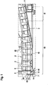
- Figure 1 shows a partial view of a cross section through a centrifuge according to the invention.
- a rotor with a cylindrical section 2 and a conical section 3 can be seen, the rotor in a housing 10 is rotatably mounted.
- a worm 4 with a plurality of worm flights 40 is rotatably mounted inside the rotor.
- the rotor has a first end face 6, which is located on the left in the plane of the drawing. On the right in the plane of the drawing, the rotor also has a second end face 5, which has a smaller diameter than the first end face 6.
- the non-visible axis of rotation of the rotor is aligned horizontally.
- a flange 8 is arranged on the first end face 6 of the rotor and fastened by means of several screws 80.
- the flange 8 has a plurality of openings 83 evenly distributed over its circumference.
- a plurality of weir plates 7, which are distributed over its circumference and partially cover the openings 83, are also fastened to the flange 8 by means of screws 71. Because the weir plates 7 partially cover the openings 83 of the flange 8, the weir plates 7 define a first radial outlet edge 85 for the outlet of a liquid on the first end face 6.
- a clarifying part 90 of the rotor, in which the liquid accumulates, and the solid part 91 of the rotor, in which the separated solid is located within the rotor and is continuously transported away via the second end face 5 by means of the screw flights 40, can also be seen.
- the clarifying part 90 can also be referred to as a sump and the solid part 91 as a dry beach. Accordingly, the liquid is discharged from the rotor via the outlet edge 85 defined in the image plane on the left end face 6 by the correspondingly positioned weir plates 7.
- the weir plates 7 are adjustable in terms of their radial height in relation to the radial course of the flange 8 and can be fixed to the flange 8 by means of the screws 71.
- the flange 8 has a plurality of threaded bores corresponding to the screws 71, which are arranged distributed in its radial course.
- the weir plates 7 have on their side facing the flange 8 an elastically deformable coating made of an elastomer, which is shown in FIG Fig. 1 is not visible. The coating prevents the formation of gaps between the flange 8 and the weir plates 7, so that no bacteria can lodge therein.
- a centrifuge can also be used in hygienic applications, in particular in the food industry.
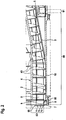
- Figure 2 shows an arrangement according to Fig. 1 It can be seen that the weir plates 7 have been adjusted to a radially higher level, so that the liquid level 9 is higher than in the illustration according to FIG Fig. 1 . In this way, the clarifying part 90 is off in relation to the illustration Fig. 1 larger, whereas the dry part 91 is smaller.
- the centrifuge can be adapted to the operating requirements, since the ratio of clarifying part 90 and dry part 91 can also be variably adapted as a result.
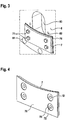
- FIG 3 shows a perspective view of a weir plate 7 which is arranged on the flange 8.
- the weir plate 7 partially covers the opening 83 of the flange 8.
- the weir plate 7 is attached to the flange by means of four screws 71.
- the screws 71 are screwed into threaded bores 82 of the flange 8.
- a coating 70 of the weir plate 7 is visible, which was squeezed between the weir plate 7 and the flange 8 by means of the screws 71 after the weir plate 7 was fastened. In this way, the coating 70 squeezed between the weir plate 7 and the flange 8 prevents gaps from forming between these elements in which breeding grounds for bacteria could arise.
- Figure 4 shows a perspective view of the weir plate 7 according to FIG Fig. 3 , the side of the weir plate 7 facing the flange being shown. It can be seen that the coating 70 is around the area of the through holes 72 of the weir plate 7 has perforations 73. These openings 73 serve to achieve a stable connection between the weir plate 7 and the flange 8 in that the areas around the through holes 72 are free of a coating 70. In this way, the weir plate 7 and the flange 8 lie directly on one another in the areas around the through holes 72, so that a stable connection between the two components is made possible.
Landscapes
- Centrifugal Separators (AREA)
Description
- Die Erfindung betrifft eine Zentrifuge, insbesondere Dekantierzentrifuge, zur Separation einer Suspension in mehrere Bestandteile, mit einem Rotor und einer innerhalb des Rotors angeordneten Schnecke, wobei der Rotor zumindest teilweise als Vollmantelrotor mit zumindest einem zylindrischen Abschnitt und einem konischen Abschnitt ausgeführt ist, wobei der Rotor eine erste den zylindrischen Abschnitt des Rotors abschließende Stirnseite mit einem ersten Durchmesser und eine zweite den konischen Abschnitt abschließende Stirnseite mit einem zweiten kleineren Durchmesser aufweist, wobei an der ersten Stirnseite ein Flansch mit einer oder mehreren Öffnungen angeordnet ist, wobei an dem Flansch eine oder mehrere Wehrplatten befestigt sind, welche die Öffnungen zumindest teilweise abdecken und zur Einstellung eines Flüssigkeitsniveaus innerhalb des Rotors angeordnet sind und eine erste radiale Auslasskante zum Auslass einer Flüssigkeit an der ersten Stirnseite bilden.
- Derartige Zentrifugen sind bekannt, zum Beispiel aus
DE 41 06 276 A1 oderDE 43 20 265 A1 . Es hat sich als nachteilig gezeigt, dass sich in dem Kontaktbereich zwischen der Wehrplatte und dem Rotor Brutplätze für Bakterien bilden können. Daher kommen derartige Zentrifugen nach dem bekannten Stand der Technik nicht in Anwendungen zum Einsatz, in denen hygienische Sauberkeit erforderlich ist. - Die Aufgabe der Erfindung ist es daher, eine Zentrifuge bereitzustellen, die in Hygieneanwendungen einsetzbar ist.
- Diese Aufgabe wird erfindungsgemäß durch eine Zentrifuge gemäß Anspruch 1 gelöst. Vorteilhafte Weiterbildungen der Erfindung sind in den abhängigen Ansprüchen angegeben.
- Besonders vorteilhaft bei der Zentrifuge, insbesondere Dekantierzentrifuge, zur Separation einer Suspension in mehrere Bestandteile, mit einem Rotor und einer innerhalb des Rotors angeordneten Schnecke, wobei der Rotor zumindest teilweise als Vollmantelrotor mit zumindest einem zylindrischen Abschnitt und einem konischen Abschnitt ausgeführt ist, wobei der Rotor eine erste den zylindrischen Abschnitt des Rotors abschließende Stirnseite mit einem ersten Durchmesser und eine zweite den konischen Abschnitt abschließende Stirnseite mit einem zweiten kleineren Durchmesser aufweist, wobei an der ersten Stirnseite ein Flansch mit einer oder mehreren Öffnungen angeordnet ist, wobei an dem Flansch eine oder mehrere Wehrplatten befestigt sind, welche die Öffnungen zumindest teilweise abdecken und zur Einstellung eines Flüssigkeitsniveaus innerhalb des Rotors angeordnet sind und eine erste radiale Auslasskante zum Auslass einer Flüssigkeit an der ersten Stirnseite bilden, ist es, dass die Wehrplatten zumindest teilweise auf ihrer zu dem Flansch zugewandten Seite eine elastisch verformbare Beschichtung aufweisen.
- Die Wehrplatten, die zumindest teilweise auf ihrer zu dem Flansch zugewandten Seite eine elastisch verformbare Beschichtung aufweisen, dienen zur Vermeidung einer Spaltenbildung und somit zur Abdichtung zwischen dem Rotor und den Wehrplatten. Bei der Befestigung der Wehrplatten an dem Flansch wird die Beschichtung aufgrund ihrer elastischen Verformbarkeit zwischen den Wehrplatten und dem Flansch gequetscht, sodass mögliche Spalten zwischen den Wehrplatten und dem Flansch verschlossen werden. Auf diese Weise wird verhindert, dass sich zwischen den Wehrplatten und dem Flansch etwaige Spalten bilden, die als Brutstätten für Bakterien fungieren können, welche die über die erste Stirnseite auszuführende Flüssigkeit verunreinigen können. Dadurch ist eine erfindungsgemäße Zentrifuge in hygienischen Anwendungen, beispielsweise in der Lebensmittelindustrie einsetzbar, ohne dabei ein Risiko einer Verunreinigung einzugehen.
- Insbesondere kann die Separation in zwei Bestandteile erfolgen, insbesondere in einen Feststoffteil, welcher an der zweiten Stirnseite des Rotors abtransportiert wird, und einen Flüssigkeitsteil, welcher an der ersten Stirnseite des Rotors abtransportiert wird.
- Es kann sich dabei um eine Vollmantelzentrifuge, eine Dekantierzentrifuge oder eine Siebschneckenzentrifuge mit Voreindickung handeln.
- Dekantierzentrifugen arbeiten nach dem sogenannten Gegenstromprinzip. Die zu trennende Suspension wird etwa in der Mitte des Rotors aufgegeben. Der sedimentierte Feststoff wird durch die mit einer Differenzdrehzahl zum Rotor umlaufende Schnecke in Richtung zum kleinen Durchmesser und somit zur zweiten Stirnseite gefördert, während die geklärte Flüssigkeit an der ersten Stirnseite des Rotors über den Flansch überläuft.
- Das Flüssigkeitsniveau bestimmt das Verhältnis zwischen dem Klärteil und dem Trockenteil des Rotors, Das Flüssigkeitsniveau definiert dabei den Flüssigkeitsspiegel, der bei der Aufbereitung der Suspension mittels einer Rotation des Rotors entsteht. Das Flüssigkeitsniveau kann auch als Sumpfhöhe, der Klärteil als Sumpf und der Trockenteil als Trockenstrand bezeichnet werden. Dabei beginnt der Trockenteil abhängig von der Position der Wehrplatten in dem konischen Abschnitt des Rotors und endet mit der zweiten Stirnseite des Rotors an dem kleineren Durchmesser des Rotors. Der Klärteil ist somit der Teil des Rotors, in welchem ein Flüssigkeitsspiegel vorhanden ist. Der Trocknteil des Rotors beginnt somit an der ersten Stirnseite des Rotors und endet an dem Trockenteil des Rotors. Die Differenzdrehzahl zwischen der Schnecke und dem Rotor wird üblicherweise durch einen Hochleistungsantrieb realisiert, insbesondere über Keilriemen.
- Bei der Siebschneckenzentrifuge mit Voreindickung handelt es sich grundsätzlich um eine zuvor beschriebene Dekantierzentrifuge, bei der im
- Anschluss an der zweiten Stirnseite des Rotors ein Abschnitt des Rotors oder ein weiterer Rotor angeschlossen ist, welcher als Siebrotor ausgeführt ist, sodass über seinen Siebmantel Flüssigkeit, insbesondere mit kleinen Feststoffteilchen, austreten kann. Größere Feststoffteilchen werden dabei mittels der Schnecke weiter zu der freien Stirnseite des Siebrotors transportiert und an der freien Kante des Siebrotors abtransportiert. Die freie Stirnseite des Siebrotors bezeichnet dabei die dem konischen Abschnitt des Rotors abgewandte Stirnseite des Siebrotors. Bei einer derartigen Zentrifuge kann somit eine Separation der Suspension in drei Bestandteile erfolgen: Flüssigkeit über die erste Stirnseite, kleinerer Feststoff mit Flüssigkeit über den Siebmantel des Siebrotors und größerer Feststoff über die freie Stirnseite des Siebrotors. Insbesondere sind somit weitere Rotoren im Anschluss an die zweite Stirnseite des Rotors möglich.
- Bei der Vollmantelzentrifuge ist der Rotor zumindest teilweise als Vollmantelrotor ausgeführt.
- Die elastisch verformbare Beschichtung, die zumindest an der zu dem Flansch zugewandten Seite der Wehrplatten angeordnet ist, dient zur Vermeidung einer Spaltenbildung und somit zur Abdichtung zwischen dem Rotor und den Wehrplatten. Bei der Befestigung der Wehrplatten an dem Flansch wird die Beschichtung aufgrund ihrer elastischen Verformbarkeit zwischen den Wehrplatten und dem Flansch gequetscht, sodass mögliche Spalten zwischen den Wehrplatten und dem Flansch verschlossen werden. Auf diese Weise wird verhindert, dass sich zwischen den Wehrplatten und dem Flansch etwaige Spalten bilden, die als Brutstätten für Bakterien fungieren können, welche die über die erste Stirnseite auszuführende Flüssigkeit verunreinigen können. Dadurch ist eine erfindungsgemäße Zentrifuge in hygienischen Anwendungen, beispielsweise in der Lebensmittelindustrie einsetzbar, ohne dabei ein Risiko einer Verunreinigung einzugehen.
- Mit der elastischen Verformbarkeit ist eine reversible Verformbarkeit der Beschichtung gemeint. Mit dem zweiten kleineren Durchmesser an der zweiten Stirnseite des Rotors ist gemeint, dass der zweite Durchmesser im Vergleich zu dem ersten Durchmesser an der ersten Stirnseite des Rotors entsprechend dem konischen sich zur zweiten Stirnseite hin verjüngenden Verlauf des konischen Abschnitts kleiner ist.
- Insbesondere kann der Rotor derart positioniert sein, dass seine Drehachse horizontal oder in einem beliebigen Winkel zur Horizontalen ausgerichtet ist.
- Insbesondere kann der Flansch dabei lediglich eine Öffnung aufweisen. In diesem Falle würde nur eine Wehrplatte angeordnet. Bevorzugt weist der Flansch jedoch n über seinen Umfang insbesondere gleichmäßig verteilte Öffnungen, wobei n eine ganze Zahl größer 1 ist.
- Insbesondere können die Wehrplatten jeweils eine Beschichtung aufweisen, welche die Wehrplatten jeweils vollständig ummantelt.
- Insbesondere können der zylindrische Abschnitt und der konische Abschnitt des Rotors als Vollmantelrotor ausgeführt sein.
- Insbesondere kann eine derartige Zentrifuge ferner eine Antriebeinheit zur rotierenden und/oder oszillierenden Bewegung des Rotors und/oder der innerhalb des Rotors laufenden Schnecke aufweisen. Insbesondere kann eine derartige Zentrifuge ferner zumindest ein Gehäuse und/oder zumindest eine Leitung zum Transport der Suspension in den Rotor und/oder zumindest eine Waschleitung zur Einleitung einer Waschlösung, insbesondere einer Säure und/oder einer Lauge, in den Rotor und/oder zumindest jeweils einen Behälter zum Auffangen des durch die Zentrifuge separierten Stoffes aufweisen.
- Vorzugsweise weisen die Wehrplatten die elastisch verformbare Beschichtung zumindest in einem Kontaktbereich mit dem Flansch auf. Der Kontaktbereich beschreibt dabei die Flächen der Wehrplatten und des Flansches, die nach Fixierung der Wehrplatten aufeinander liegen oder anders ausgedrückt in Kontakt liegen würden. Hierdurch ist eine wirksame Verhinderung der Spaltenbildung möglich, ohne die Wehrplatte, insbesondere die dem Flansch zugewandte Seite der Wehrplatten, gänzlich zu beschichten.
- Bevorzugt besteht die Beschichtung zumindest teilweise aus einem Kunststoff. Es kann sich somit bei der Beschichtung um eine Kunststoffbeschichtung handeln. Insbesondere kann die Beschichtung aus einem Hybridwerkstoff hergestellt sein, wobei zumindest ein Teil des Werkstoffs aus einem Kunststoff besteht. Kunststoffe zeichnen sich grundsätzlich durch eine gewisse elastische Verformbarkeit aus.
- Vorzugsweise besteht die Beschichtung aus einem Elastomer, insbesondere aus Synthesekautschuk, insbesondere aus Nitrilkautschuk und/oder aus Ethylen-Propylen-Dien-Kautschuk. Also besteht die Beschichtung bevorzugt aus Elastomer, insbesondere aus Synthesekautschuk, insbesondere aus Achrylnitril-Butadien-Kautschuk, auch bezeichnet als Nitrilkautschuk und/oder aus Ethylen-Propylen-Dien-Kautschuk, auch bezeichnet als EPDM: Ethylen-Propylen-Dien; M-Gruppe. Derartige Elastomere zeichnen sich durch eine hohe elastische Verformbarkeit bei gleichzeitig vorhandener Festigkeit aus.
- Bevorzugt ist die Beschichtung antibakteriell und/oder antimikrobiell. Hierzu kann die Beschichtung insbesondere teilweise aus Silber bestehen und/oder Silber-Ionen aufweisen. Insbesondere kann Silber und/oder es können Silber-Ionen in die Materialmatrix der Beschichtung integriert sein. Eine Vermeidung von Bakterien wird dadurch verbessert.
- Vorzugsweise ist der Flansch einstückig mit dem Rotor ausgebildet. Dies kann insbesondere durch Gießen und/oder Umbördeln des Rotors und/oder Anschweißen des Flansches an den Rotor erfolgen.
- Alternativ können der Flansch und der Rotor mehrteilig ausgebildet sein, insbesondere können der Flansch und der Rotor kraftschlüssig und/oder stoffschlüssig und/oder formschlüssig miteinander verbunden sein, insbesondere mittels einer Schraubverbindung und/oder einer Vernietung.
- Bevorzugt sind die Wehrplatten an dem Flansch in mehreren verschiedenen Positionen fixierbar, insbesondere verstellbar und an dem Flansch fixierbar. Je nach gewünschtem Flüssigkeitsniveau innerhalb des Rotors können die Wehrplatten somit in radialer Richtung des Flansches in verschiedenen Positionen fixiert werden. Auf diese Weise lässt sich die Position der ersten radialen Auslasskante an dem radialen Verlauf des Flansches verstellen. Dadurch ist das Flüssigkeitsniveau flexibel einstellbar und kann je nach Trennaufgabe und/oder den Eigenschaften der aufzubereitenden Suspension optimal angepasst werden.
- Vorzugsweise sind die Wehrplatten stufenlos oder stufenweise verstellbar und an dem Flansch fixierbar. Je nach gewünschtem Flüssigkeitsniveau innerhalb des Rotors können die Wehrplatten somit in radialer Richtung des Flansches in verschiedene Positionen verstellt und an dem Flansch fixiert werden. Auf diese Weise lässt sich die Position der ersten radialen Auslasskante an dem radialen Verlauf des Flansches verstellen. Dadurch sind die Parameter der Zentrifuge flexibel und können je nach Trennaufgabe optimal angepasst werden.
- Hierzu kann der Flansch insbesondere mehrere Gewindebohrungen in unterschiedlicher Höhe bezüglich des radialen Verlaufs des Flansches aufweisen, wobei in die Gewindebohrungen Befestigungsschrauben einschraubbar sind, mittels derer die Wehrplatten fixierbar sind. Je nach gewünschtem Flüssigkeitsniveau innerhalb des Rotors können die Wehrplatten somit mittels der Befestigungsschrauben in höher positionierten oder niedriger positionierten Gewindebohrungen stufenweise fixiert werden. Mit dem Begriff einer höher positionierten Gewindebohrung ist eine entlang des Durchmessers in Richtung auf den Kreismittelpunkt des Flansches gegenüber einer niedriger positionierten Gewindebohrung verlagerte Gewindebohrung bezeichnet.
- Alternativ können die Wehrplatten auch stufenlos verstellbar sein. Beispielsweise können die Wehrplatten hierzu Langlöcher aufweisen, durch welche Befestigungsschrauben durchgreifen und die Wehrplatten in gewünschter Höhe fixieren können. Alternativ können die Wehrplatten zur stufenlosen Verstellung selbst eine oder mehrere Öffnungen aufweisen, die je nach Positionierung der Wehrplatten, insbesondere deren Verdrehung, eine höhere oder eine niedrigere Auslasskante bilden und somit ein höheres oder niedrigeres Flüssigkeitsniveau innerhalb des Rotors ermöglichen.
- Bevorzugt bestehen der Rotor und/oder Wehrplatten aus einem Metall, insbesondere aus einer Metall-Legierung. Dadurch kann eine feste Fixierung mit hoher Tragfähigkeit gewährleistet werden.
- Vorzugsweise ist die Beschichtung formschlüssig und/oder kraftschlüssig und/oder stoffschlüssig mit der/den Wehrplatte/n verbunden. Gemeint ist, dass jeweils eine Beschichtung pro jeweilige Wehrplatte erfolgt. Eine feste Verbindung zwischen Beschichtung und Wehrplatte ist wichtig, da große Kräfte darauf beim Betrieb der Zentrifuge ausgeübt werden. Insbesondere können eine Presspassung/Übermaßpassung und/oder eine Klebung zwischen der Beschichtung und der Wehrplatte erfolgen.
- Bevorzugt ist die Beschichtung mittels einer Kunststoffumspritzung der jeweiligen Wehrplatten hergestellt. Dadurch werden eine besonders feste Verbindung mit den Wehrplatten und hohe Reproduzierbarkeit ermöglicht.
- Vorzugsweise weisen die Wehrplatten jeweils zumindest ein negatives Profil auf, welches mit einem korrespondierenden positiven Profil der Beschichtung zusammenwirkt, insbesondere dass zwischen den Profilen eine Presspassung besteht. Insbesondere können die jeweilige Wehrplatte und die Beschichtung jeweils mehrere derartige Profile aufweisen.
- Bevorzugt weisen die Wehrplatten jeweils zumindest ein positives Profil auf, welches mit einem korrespondierenden negativen Profil der Beschichtung zusammenwirkt, insbesondere dass zwischen den Profilen eine Presspassung besteht. Insbesondere können die jeweilige Wehrplatte und die Beschichtung jeweils mehrere derartige Profile aufweisen.
- Vorzugsweise sind die Wehrplatten jeweils mittels Befestigungsmitteln, welche zumindest ein Durchgangsloch der Wehrplatte durchgreifen, an dem Flansch befestigt, wobei die Beschichtung in einem um das Durchgangsloch umliegenden Bereich eine Durchbrechung aufweist, sodass in diesem um das Durchgangsloch umliegenden Bereich ein unmittelbarer Kontakt zwischen den Wehrplatten und dem Flansch besteht. Mittels einer derartigen Durchbrechung der Beschichtung wird gewährleistet, dass eine tragfähige Verbindung, insbesondere Schraubverbindung, zwischen den Wehrplatten und dem Flansch möglich ist. Die Tragfähigkeit wird dadurch möglich ist, dass in diesem Bereich eben keine Beschichtung vorhanden ist, sodass in diesem Bereich die Wehrplatte und/oder die Wehrplatten unmittelbar an dem Flansch anliegt/anliegen, sodass gerade keine elastisch verformbare Beschichtung dazwischen liegt.
- Alternativ oder kumulativ kann die Beschichtung derartige Durchbrechungen auf der dem Flansch abgewandten Seite der Wehrplatte aufweisen, sodass in dem um das Durchgangsloch umliegenden Bereich ein unmittelbarer Kontakt zwischen den Befestigungsmitteln und der Wehrplatte besteht.
- Ein Ausführungsbeispiel der Erfindung ist in den Figuren dargestellt. Es zeigen:
- Fig. 1
- eine Teilansicht eines Querschnitts durch eine erfindungsgemäße Zentrifuge mit Wehrplatten in einer ersten radialen Position;
- Fig. 2
- eine Teilansicht eines Querschnitts durch eine erfindungsgemäße Zentrifuge mit Wehrplatten in einer zweiten radialen Position;
- Fig. 3
- eine perspektivische Ansicht einer Wehrplatte an einem Flansch;
- Fig. 4
- eine perspektivische Ansicht der Wehrplatte nach
Fig. 3 . - Identische Bauteile und Baugruppen sind in den Figuren mit denselben Bezugszeichen gekennzeichnet.
-
Figur 1 zeigt eine Teilansicht eines Querschnitts durch eine erfindungsgemäße Zentrifuge. Dabei ist ein Rotor mit einem zylindrischen Abschnitt 2 und einem konischen Abschnitt 3 erkennbar, wobei der Rotor in einem Gehäuse 10 drehbar gelagert ist. Innerhalb des Rotors ist ferner eine Schnecke 4 mit einer Vielzahl von Schneckengängen 40 drehbar gelagert. Der Rotor weist dabei eine erste Stirnseite 6 auf, welche sich in der Zeichenebene links befindet. Rechts in der Zeichenebene weist der Rotor ferner eine zweite Stirnseite 5 auf, welche einen gegenüber der ersten Stirnseite 6 kleineren Durchmesser aufweist. Die in derFigur 1 nicht sichtbare Drehachse des Rotors ist horizontal ausgerichtet. - An der ersten Stirnseite 6 des Rotors ist ein Flansch 8 angeordnet und mittels mehreren Schrauben 80 befestigt. Der Flansch 8 weist mehrere über seinen Umfang gleichmäßig verteilte Öffnungen 83 auf. An dem Flansch 8 sind ferner mehrere über seinen Umfang verteilte Wehrplatten 7, welche die Öffnungen 83 teilweise abdecken, mittels Schrauben 71 befestigt. Dadurch, dass die Wehplatten 7 die Öffnungen 83 des Flansches 8 teilweise abdecken, definieren die Wehrplatten 7 eine erste radiale Auslasskante 85 zum Auslass einer Flüssigkeit an der ersten Stirnseite 6.
- Dadurch entsteht bei der Aufbereitung einer Suspension mittels der Zentrifuge ein Flüssigkeitsspiegel 9 innerhalb des Rotors. Die Aufbereitung erfolgt dadurch, dass der Rotor und die Schnecke 4 mit einer Differenzdrehzahl rotiert werden. Ferner erkennbar ist ein Klärteil 90 des Rotors, in welchem sich die Flüssigkeit staut, und der Feststoffteil 91 des Rotors, in welchem sich der separierte Feststoff innerhalb des Rotors befindet und mittels der Schneckengänge 40 kontinuierlich über die zweite Stirnseite 5 abtransportiert wird. Der Klärteil 90 kann ferner als Sumpf und der Feststoffteil 91 als Trockenstrand bezeichnet werden. Dementsprechend wird die Flüssigkeit über die in der Bildebene an der linken Stirnseite 6 durch die entsprechend positionierten Wehrplatten 7 definierte Auslasskante 85 aus dem Rotor abgeführt.
- Die Wehrplatten 7 sind bezüglich ihrer radialen Höhe in Bezug auf den radialen Verlauf des Flansches 8 verstellbar und an dem Flansch 8 mittels der Schrauben 71 fixierbar. Hierzu weist der Flansch 8 mehrere zu den Schrauben 71 korrespondierende Gewindebohrungen auf, welche in seinem radialen Verlauf verteilt angeordnet sind. Über die Verstellung der Wehrplatten 7 kann die radiale Position der Auslasskante 85 und damit das Flüssigkeitsniveau 9 innerhalb des Rotors eingestellt werden. Ferner weisen die Wehrplatten 7 auf ihrer zu dem Flansch 8 zugewandten Seite eine elastisch verformbare Beschichtung aus einem Elastomer auf, welche in
Fig. 1 nicht sichtbar ist. Die Beschichtung verhindert eine Spaltenbildung zwischen dem Flansch 8 und den Wehrplatten 7, sodass sich darin keine Bakterien einnisten können. Dadurch kann eine derartige Zentrifuge auch in hygienischen Anwendungen, insbesondere in der Lebensmittelindustrie eingesetzt werden. -
Figur 2 zeigt eine Anordnung nachFig. 1 , wobei zu erkennen ist, dass die Wehrplatten 7 auf ein radial höheres Niveau verstellt wurden, sodass der Flüssigkeitsspiegel 9 höher liegt als bei der Darstellung nachFig. 1 . Auf diese Weise ist der Klärteil 90 gegenüber der Darstellung ausFig. 1 größer, wohingegen der Trockenteil 91 kleiner ist. - Durch die Möglichkeit der radial variablen Positionierung der Wehrplatten 7 an dem Flansch 8 kann die Zentrifuge den Betriebsanforderungen angepasst werden, da hierdurch das Verhältnis von Klärteil 90 und Trockenteil 91 ebenfalls variabel anpassbar ist.
-
Figur 3 zeigt eine perspektivische Ansicht einer Wehrplatte 7, welche an dem Flansch 8 angeordnet ist. Die Wehrplatte 7 verdeckt dabei teilweise die Öffnung 83 des Flansches 8. Die Wehrplatte 7 ist dabei mittels vier Schrauben 71 an dem Flansch befestigt. Hierzu sind die Schrauben 71 in Gewindebohrungen 82 des Flansches 8 angeschraubt. Ferner ist eine Beschichtung 70 der Wehrplatte 7 sichtbar, welche nach dem Befestigen der Wehrplatte 7 mittels der Schrauben 71 zwischen der Wehrplatte 7 und dem Flansch 8 gequetscht wurde. Auf diese Weise wird durch die zwischen der Wehrplatte 7 und dem Flansch 8 gequetschte Beschichtung 70 verhindert, dass sich zwischen diesen Elementen Spalten bilden, in denen Brutstätten für Bakterien entstehen könnten. -
Figur 4 zeigt eine perspektivische Ansicht der Wehrplatte 7 nachFig. 3 , wobei die zu dem Flansch zugewandte Seite der Wehrplatte 7 dargestellt ist. Erkennbar ist, dass die Beschichtung 70 um den Bereich der Durchgangslöcher 72 der Wehrplatte 7 Durchbrechungen 73 aufweist. Diese Durchbrechungen 73 dienen dazu, eine tragfähige Verbindung zwischen der Wehrplatte 7 und dem Flansch 8 zu erreichen, indem die Bereiche um die Durchgangslöcher 72 frei von einer Beschichtung 70 sind. Auf diese Weise liegt die Wehrplatte 7 und der Flansch 8 in den Bereichen um die Durchgangslöcher 72 unmittelbar aufeinander auf, sodass eine tragfähige Verbindung zwischen den beiden Bauteilen ermöglicht wird.
Claims (14)
- Zentrifuge, insbesondere Dekantierzentrifuge, zur Separation einer Suspension in mehrere Bestandteile, mit einem Rotor und einer innerhalb des Rotors angeordneten Schnecke (4), wobei der Rotor zumindest teilweise als Vollmantelrotor mit zumindest einem zylindrischen Abschnitt (2) und einem konischen Abschnitt (3) ausgeführt ist, wobei der Rotor eine erste den zylindrischen Abschnitt (2) des Rotors abschließende Stirnseite (6) mit einem ersten Durchmesser und eine zweite den konischen Abschnitt (3) abschließende Stirnseite (5) mit einem zweiten kleineren Durchmesser aufweist, wobei an der ersten Stirnseite (6) ein Flansch (8) mit einer oder mehreren Öffnungen (83) angeordnet ist, wobei an dem Flansch (8) eine oder mehrere Wehrplatten (7) befestigt sind, welche die Öffnungen (83) zumindest teilweise abdecken und zur Einstellung eines Flüssigkeitsniveaus (9) innerhalb des Rotors angeordnet sind und eine erste radiale Auslasskante (85) zum Auslass einer Flüssigkeit an der ersten Stirnseite (6) bilden, dadurch gekennzeichnet, dass die Wehrplatten (7) zumindest teilweise auf ihrer zu dem Flansch (8) zugewandten Seite eine elastisch verformbare Beschichtung (70) aufweisen.
- Zentrifuge nach Anspruch 1, dadurch gekennzeichnet, dass die Wehrplatten (7) die elastisch verformbare Beschichtung (70) zumindest in einem Kontaktbereich mit dem Flansch (8) aufweisen.
- Zentrifuge nach einem der vorherigen Ansprüche 1 oder 2, dadurch gekennzeichnet, dass die Beschichtung (70) zumindest teilweise aus einem Kunststoff besteht.
- Zentrifuge nach einem der vorherigen Ansprüche, dadurch gekennzeichnet, dass die Beschichtung (70) aus einem Elastomer, insbesondere aus Synthesekautschuk, insbesondere aus Nitrilkautschuk und/oder aus Ethylen-Propylen-Dien-Kautschuk besteht.
- Zentrifuge nach einem der vorherigen Ansprüche, dadurch gekennzeichnet, dass die Beschichtung (70) antibakteriell und/oder antimikrobiell ist.
- Zentrifuge nach einem der vorherigen Ansprüche, dadurch gekennzeichnet, dass der Flansch (8) einstückig mit dem Rotor ausgebildet ist.
- Zentrifuge nach einem der vorherigen Ansprüche, dadurch gekennzeichnet, dass die Wehrplatten (7) an dem Flansch (8) in mehreren verschiedenen Positionen fixierbar sind.
- Zentrifuge nach einem der vorherigen Ansprüche, dadurch gekennzeichnet, dass die Wehrplatten (7) stufenlos oder stufenweise verstellbar und an dem Flansch (8) fixierbar sind.
- Zentrifuge nach einem der vorherigen Ansprüche, dadurch gekennzeichnet, dass der Rotor und/oder Wehrplatten (7) aus einem Metall, insbesondere aus einer Metall-Legierung bestehen.
- Zentrifuge nach einem der vorherigen Ansprüche, dadurch gekennzeichnet, dass die Beschichtung (70) formschlüssig und/oder kraftschlüssig und/oder stoffschlüssig mit den Wehrplatten (7) verbunden ist.
- Zentrifuge nach einem der vorherigen Ansprüche, dadurch gekennzeichnet, dass die Beschichtung (70) mittels einer Kunststoffumspritzung der jeweiligen Wehrplatten (7) hergestellt ist.
- Zentrifuge nach einem der vorherigen Ansprüche, dadurch gekennzeichnet, dass die Wehrplatten (7) jeweils zumindest ein negatives Profil aufweisen, welches mit einem korrespondierenden positiven Profil der Beschichtung (70) zusammenwirkt, insbesondere dass zwischen den Profilen eine Presspassung besteht.
- Zentrifuge nach einem der vorherigen Ansprüche, dadurch gekennzeichnet, dass die Wehrplatten (7) jeweils zumindest ein positives Profil aufweisen, welches mit einem korrespondierenden negativen Profil der Beschichtung (70) zusammenwirkt, insbesondere dass zwischen den Profilen eine Presspassung besteht.
- Zentrifuge nach einem der vorherigen Ansprüche, dadurch gekennzeichnet, dass die Wehrplatten (7) jeweils mittels Befestigungsmitteln (71), welche zumindest ein Durchgangsloch (72) der Wehrplatte (7) durchgreifen, an dem Flansch (8) befestigt sind, wobei die Beschichtung (70) in einem um das Durchgangsloch (72) umliegenden Bereich eine Durchbrechung (73) aufweist, sodass in diesem um das Durchgangsloch (72) umliegenden Bereich ein unmittelbarer Kontakt zwischen den Wehrplatten (7) und dem Flansch (9) besteht.
Priority Applications (2)
| Application Number | Priority Date | Filing Date | Title |
|---|---|---|---|
| EP18000773.4A EP3628407B1 (de) | 2018-09-28 | 2018-09-28 | Zentrifuge mit beschichteten wehrplatten |
| US16/581,852 US20200101472A1 (en) | 2018-09-28 | 2019-09-25 | Centrifuge with coated weir plates |
Applications Claiming Priority (1)
| Application Number | Priority Date | Filing Date | Title |
|---|---|---|---|
| EP18000773.4A EP3628407B1 (de) | 2018-09-28 | 2018-09-28 | Zentrifuge mit beschichteten wehrplatten |
Publications (2)
| Publication Number | Publication Date |
|---|---|
| EP3628407A1 EP3628407A1 (de) | 2020-04-01 |
| EP3628407B1 true EP3628407B1 (de) | 2021-07-28 |
Family
ID=63720441
Family Applications (1)
| Application Number | Title | Priority Date | Filing Date |
|---|---|---|---|
| EP18000773.4A Active EP3628407B1 (de) | 2018-09-28 | 2018-09-28 | Zentrifuge mit beschichteten wehrplatten |
Country Status (2)
| Country | Link |
|---|---|
| US (1) | US20200101472A1 (de) |
| EP (1) | EP3628407B1 (de) |
Families Citing this family (1)
| Publication number | Priority date | Publication date | Assignee | Title |
|---|---|---|---|---|
| CN116510924B (zh) * | 2023-05-11 | 2025-10-24 | 天地(唐山)矿业科技有限公司 | 卧式沉降离心机溢流液位无级调节装置 |
Family Cites Families (4)
| Publication number | Priority date | Publication date | Assignee | Title |
|---|---|---|---|---|
| DE4106276A1 (de) * | 1991-02-28 | 1992-09-03 | Kloeckner Humboldt Deutz Ag | Schneckenzentrifuge |
| DE4320265C2 (de) * | 1993-06-18 | 1995-08-03 | Westfalia Separator Ag | Wehr für Vollmantelschleudertrommeln |
| JP2001314779A (ja) * | 2000-05-11 | 2001-11-13 | Tomoe Engineering Co Ltd | デカンタ型遠心分離機、この運転方法、及びこれを備えたシステム |
| KR101068577B1 (ko) * | 2008-12-24 | 2011-09-30 | 주식회사 로얄정공 | 다단조절 슬로트 댐 플레이트가 장착된 원심분리기와 다단조절 슬로트 댐 플레이트를 이용한 원심분리기의 분리액 회수율 조절방법 |
-
2018
- 2018-09-28 EP EP18000773.4A patent/EP3628407B1/de active Active
-
2019
- 2019-09-25 US US16/581,852 patent/US20200101472A1/en not_active Abandoned
Also Published As
| Publication number | Publication date |
|---|---|
| EP3628407A1 (de) | 2020-04-01 |
| US20200101472A1 (en) | 2020-04-02 |
Similar Documents
| Publication | Publication Date | Title |
|---|---|---|
| DE1404994B2 (de) | Schneckenpresse zum Abscheiden von Flüssigkeit aus plastischen Massen | |
| EP2155353B1 (de) | Pressschneckenseparator | |
| DE19631679A1 (de) | Vorrichtung zum Schleifen und Vereinheitlichen von Körnern und Sieb mit ringförmigem Arbeitsraum zur Verwendung in der Vorrichtung | |
| DE2138925A1 (de) | Klassiersieb | |
| DE3224204A1 (de) | Zentrifuge | |
| EP2872256B1 (de) | Vollmantel-schneckenzentrifuge mit überlaufwehr | |
| EP3628407A1 (de) | Zentrifuge mit beschichteten wehrplatten | |
| DE102004042888A1 (de) | Selbstentleerender Separator mit Tellerpaket | |
| DE2750499C3 (de) | Sortierer für Fasersuspension | |
| DE3210385C2 (de) | Sortiertrommel | |
| DE102022001886A1 (de) | Zentrifuge mit Wehrplatten mit einliegender Dichtung | |
| DE10020646C1 (de) | Extruder | |
| DE3432811A1 (de) | Drehsieb | |
| EP1949966B1 (de) | Vollmantel-Schneckenzentrifuge mit einer Stauscheibe | |
| EP3452765B1 (de) | Vorrichtung zur erzeugung von eis, insbesondere scherbeneis | |
| EP1337344A1 (de) | Vollmantel-schneckenzentrifuge mit verteiler | |
| WO2018158260A1 (de) | Lüfterrad | |
| DE60306063T2 (de) | Siebvorrichtung | |
| DE102011102073B4 (de) | Vorrichtung zum Entfernen von Siebgut aus einer Flüssigkeit | |
| DE202016005250U1 (de) | Trogförderer zum Fördern eines Gutes | |
| DE1803266C3 (de) | Vorrichtung zum Entfernen von Flüssigkeiten aus elastomerem oder polymerem Material | |
| AT525727B1 (de) | Pressschneckenseparator | |
| EP1640052A1 (de) | Vorrichtung zum Trennen von Feststoffpartikeln aus einer Flüssigkeit | |
| DE9100126U1 (de) | Vorrichtung zum Entfernen von Rechen- und/oder Siebgut aus einem Gerinne strömender Flüssigkeit | |
| DE10319842B4 (de) | Entgasungseinrichtung für einen Extruder |
Legal Events
| Date | Code | Title | Description |
|---|---|---|---|
| PUAI | Public reference made under article 153(3) epc to a published international application that has entered the european phase |
Free format text: ORIGINAL CODE: 0009012 |
|
| STAA | Information on the status of an ep patent application or granted ep patent |
Free format text: STATUS: THE APPLICATION HAS BEEN PUBLISHED |
|
| AK | Designated contracting states |
Kind code of ref document: A1 Designated state(s): AL AT BE BG CH CY CZ DE DK EE ES FI FR GB GR HR HU IE IS IT LI LT LU LV MC MK MT NL NO PL PT RO RS SE SI SK SM TR |
|
| AX | Request for extension of the european patent |
Extension state: BA ME |
|
| STAA | Information on the status of an ep patent application or granted ep patent |
Free format text: STATUS: REQUEST FOR EXAMINATION WAS MADE |
|
| 17P | Request for examination filed |
Effective date: 20200928 |
|
| RBV | Designated contracting states (corrected) |
Designated state(s): AL AT BE BG CH CY CZ DE DK EE ES FI FR GB GR HR HU IE IS IT LI LT LU LV MC MK MT NL NO PL PT RO RS SE SI SK SM TR |
|
| GRAP | Despatch of communication of intention to grant a patent |
Free format text: ORIGINAL CODE: EPIDOSNIGR1 |
|
| STAA | Information on the status of an ep patent application or granted ep patent |
Free format text: STATUS: GRANT OF PATENT IS INTENDED |
|
| INTG | Intention to grant announced |
Effective date: 20210224 |
|
| GRAS | Grant fee paid |
Free format text: ORIGINAL CODE: EPIDOSNIGR3 |
|
| GRAA | (expected) grant |
Free format text: ORIGINAL CODE: 0009210 |
|
| STAA | Information on the status of an ep patent application or granted ep patent |
Free format text: STATUS: THE PATENT HAS BEEN GRANTED |
|
| AK | Designated contracting states |
Kind code of ref document: B1 Designated state(s): AL AT BE BG CH CY CZ DE DK EE ES FI FR GB GR HR HU IE IS IT LI LT LU LV MC MK MT NL NO PL PT RO RS SE SI SK SM TR |
|
| REG | Reference to a national code |
Ref country code: GB Ref legal event code: FG4D Free format text: NOT ENGLISH |
|
| REG | Reference to a national code |
Ref country code: CH Ref legal event code: EP |
|
| REG | Reference to a national code |
Ref country code: DE Ref legal event code: R096 Ref document number: 502018006266 Country of ref document: DE |
|
| REG | Reference to a national code |
Ref country code: AT Ref legal event code: REF Ref document number: 1414228 Country of ref document: AT Kind code of ref document: T Effective date: 20210815 |
|
| REG | Reference to a national code |
Ref country code: IE Ref legal event code: FG4D Free format text: LANGUAGE OF EP DOCUMENT: GERMAN |
|
| REG | Reference to a national code |
Ref country code: LT Ref legal event code: MG9D |
|
| REG | Reference to a national code |
Ref country code: NL Ref legal event code: MP Effective date: 20210728 |
|
| PG25 | Lapsed in a contracting state [announced via postgrant information from national office to epo] |
Ref country code: BG Free format text: LAPSE BECAUSE OF FAILURE TO SUBMIT A TRANSLATION OF THE DESCRIPTION OR TO PAY THE FEE WITHIN THE PRESCRIBED TIME-LIMIT Effective date: 20211028 Ref country code: LT Free format text: LAPSE BECAUSE OF FAILURE TO SUBMIT A TRANSLATION OF THE DESCRIPTION OR TO PAY THE FEE WITHIN THE PRESCRIBED TIME-LIMIT Effective date: 20210728 Ref country code: PT Free format text: LAPSE BECAUSE OF FAILURE TO SUBMIT A TRANSLATION OF THE DESCRIPTION OR TO PAY THE FEE WITHIN THE PRESCRIBED TIME-LIMIT Effective date: 20211129 Ref country code: NL Free format text: LAPSE BECAUSE OF FAILURE TO SUBMIT A TRANSLATION OF THE DESCRIPTION OR TO PAY THE FEE WITHIN THE PRESCRIBED TIME-LIMIT Effective date: 20210728 Ref country code: NO Free format text: LAPSE BECAUSE OF FAILURE TO SUBMIT A TRANSLATION OF THE DESCRIPTION OR TO PAY THE FEE WITHIN THE PRESCRIBED TIME-LIMIT Effective date: 20211028 Ref country code: SE Free format text: LAPSE BECAUSE OF FAILURE TO SUBMIT A TRANSLATION OF THE DESCRIPTION OR TO PAY THE FEE WITHIN THE PRESCRIBED TIME-LIMIT Effective date: 20210728 Ref country code: RS Free format text: LAPSE BECAUSE OF FAILURE TO SUBMIT A TRANSLATION OF THE DESCRIPTION OR TO PAY THE FEE WITHIN THE PRESCRIBED TIME-LIMIT Effective date: 20210728 Ref country code: FI Free format text: LAPSE BECAUSE OF FAILURE TO SUBMIT A TRANSLATION OF THE DESCRIPTION OR TO PAY THE FEE WITHIN THE PRESCRIBED TIME-LIMIT Effective date: 20210728 Ref country code: ES Free format text: LAPSE BECAUSE OF FAILURE TO SUBMIT A TRANSLATION OF THE DESCRIPTION OR TO PAY THE FEE WITHIN THE PRESCRIBED TIME-LIMIT Effective date: 20210728 Ref country code: HR Free format text: LAPSE BECAUSE OF FAILURE TO SUBMIT A TRANSLATION OF THE DESCRIPTION OR TO PAY THE FEE WITHIN THE PRESCRIBED TIME-LIMIT Effective date: 20210728 |
|
| PG25 | Lapsed in a contracting state [announced via postgrant information from national office to epo] |
Ref country code: PL Free format text: LAPSE BECAUSE OF FAILURE TO SUBMIT A TRANSLATION OF THE DESCRIPTION OR TO PAY THE FEE WITHIN THE PRESCRIBED TIME-LIMIT Effective date: 20210728 Ref country code: LV Free format text: LAPSE BECAUSE OF FAILURE TO SUBMIT A TRANSLATION OF THE DESCRIPTION OR TO PAY THE FEE WITHIN THE PRESCRIBED TIME-LIMIT Effective date: 20210728 Ref country code: GR Free format text: LAPSE BECAUSE OF FAILURE TO SUBMIT A TRANSLATION OF THE DESCRIPTION OR TO PAY THE FEE WITHIN THE PRESCRIBED TIME-LIMIT Effective date: 20211029 |
|
| PG25 | Lapsed in a contracting state [announced via postgrant information from national office to epo] |
Ref country code: DK Free format text: LAPSE BECAUSE OF FAILURE TO SUBMIT A TRANSLATION OF THE DESCRIPTION OR TO PAY THE FEE WITHIN THE PRESCRIBED TIME-LIMIT Effective date: 20210728 |
|
| REG | Reference to a national code |
Ref country code: DE Ref legal event code: R097 Ref document number: 502018006266 Country of ref document: DE Ref country code: CH Ref legal event code: PL |
|
| REG | Reference to a national code |
Ref country code: BE Ref legal event code: MM Effective date: 20210930 |
|
| PG25 | Lapsed in a contracting state [announced via postgrant information from national office to epo] |
Ref country code: SM Free format text: LAPSE BECAUSE OF FAILURE TO SUBMIT A TRANSLATION OF THE DESCRIPTION OR TO PAY THE FEE WITHIN THE PRESCRIBED TIME-LIMIT Effective date: 20210728 Ref country code: SK Free format text: LAPSE BECAUSE OF FAILURE TO SUBMIT A TRANSLATION OF THE DESCRIPTION OR TO PAY THE FEE WITHIN THE PRESCRIBED TIME-LIMIT Effective date: 20210728 Ref country code: RO Free format text: LAPSE BECAUSE OF FAILURE TO SUBMIT A TRANSLATION OF THE DESCRIPTION OR TO PAY THE FEE WITHIN THE PRESCRIBED TIME-LIMIT Effective date: 20210728 Ref country code: MC Free format text: LAPSE BECAUSE OF FAILURE TO SUBMIT A TRANSLATION OF THE DESCRIPTION OR TO PAY THE FEE WITHIN THE PRESCRIBED TIME-LIMIT Effective date: 20210728 Ref country code: EE Free format text: LAPSE BECAUSE OF FAILURE TO SUBMIT A TRANSLATION OF THE DESCRIPTION OR TO PAY THE FEE WITHIN THE PRESCRIBED TIME-LIMIT Effective date: 20210728 Ref country code: CZ Free format text: LAPSE BECAUSE OF FAILURE TO SUBMIT A TRANSLATION OF THE DESCRIPTION OR TO PAY THE FEE WITHIN THE PRESCRIBED TIME-LIMIT Effective date: 20210728 Ref country code: AL Free format text: LAPSE BECAUSE OF FAILURE TO SUBMIT A TRANSLATION OF THE DESCRIPTION OR TO PAY THE FEE WITHIN THE PRESCRIBED TIME-LIMIT Effective date: 20210728 |
|
| PLBE | No opposition filed within time limit |
Free format text: ORIGINAL CODE: 0009261 |
|
| STAA | Information on the status of an ep patent application or granted ep patent |
Free format text: STATUS: NO OPPOSITION FILED WITHIN TIME LIMIT |
|
| 26N | No opposition filed |
Effective date: 20220429 |
|
| PG25 | Lapsed in a contracting state [announced via postgrant information from national office to epo] |
Ref country code: LU Free format text: LAPSE BECAUSE OF NON-PAYMENT OF DUE FEES Effective date: 20210928 Ref country code: IT Free format text: LAPSE BECAUSE OF FAILURE TO SUBMIT A TRANSLATION OF THE DESCRIPTION OR TO PAY THE FEE WITHIN THE PRESCRIBED TIME-LIMIT Effective date: 20210728 Ref country code: IE Free format text: LAPSE BECAUSE OF NON-PAYMENT OF DUE FEES Effective date: 20210928 Ref country code: FR Free format text: LAPSE BECAUSE OF NON-PAYMENT OF DUE FEES Effective date: 20210928 Ref country code: BE Free format text: LAPSE BECAUSE OF NON-PAYMENT OF DUE FEES Effective date: 20210930 |
|
| PG25 | Lapsed in a contracting state [announced via postgrant information from national office to epo] |
Ref country code: LI Free format text: LAPSE BECAUSE OF NON-PAYMENT OF DUE FEES Effective date: 20210930 Ref country code: CH Free format text: LAPSE BECAUSE OF NON-PAYMENT OF DUE FEES Effective date: 20210930 |
|
| GBPC | Gb: european patent ceased through non-payment of renewal fee |
Effective date: 20220928 |
|
| REG | Reference to a national code |
Ref country code: DE Ref legal event code: R082 Ref document number: 502018006266 Country of ref document: DE Representative=s name: PATENTANWALTSKANZLEI METHLING DR. FRANK-OLIVER, DE Ref country code: DE Ref legal event code: R082 Ref document number: 502018006266 Country of ref document: DE Representative=s name: METHLING, FRANK-OLIVER, DIPL.-ING. DR.-ING., DE |
|
| PG25 | Lapsed in a contracting state [announced via postgrant information from national office to epo] |
Ref country code: CY Free format text: LAPSE BECAUSE OF FAILURE TO SUBMIT A TRANSLATION OF THE DESCRIPTION OR TO PAY THE FEE WITHIN THE PRESCRIBED TIME-LIMIT Effective date: 20210728 |
|
| PG25 | Lapsed in a contracting state [announced via postgrant information from national office to epo] |
Ref country code: HU Free format text: LAPSE BECAUSE OF FAILURE TO SUBMIT A TRANSLATION OF THE DESCRIPTION OR TO PAY THE FEE WITHIN THE PRESCRIBED TIME-LIMIT; INVALID AB INITIO Effective date: 20180928 |
|
| PG25 | Lapsed in a contracting state [announced via postgrant information from national office to epo] |
Ref country code: GB Free format text: LAPSE BECAUSE OF NON-PAYMENT OF DUE FEES Effective date: 20220928 |
|
| PG25 | Lapsed in a contracting state [announced via postgrant information from national office to epo] |
Ref country code: MK Free format text: LAPSE BECAUSE OF FAILURE TO SUBMIT A TRANSLATION OF THE DESCRIPTION OR TO PAY THE FEE WITHIN THE PRESCRIBED TIME-LIMIT Effective date: 20210728 |
|
| PG25 | Lapsed in a contracting state [announced via postgrant information from national office to epo] |
Ref country code: MT Free format text: LAPSE BECAUSE OF FAILURE TO SUBMIT A TRANSLATION OF THE DESCRIPTION OR TO PAY THE FEE WITHIN THE PRESCRIBED TIME-LIMIT Effective date: 20210728 |
|
| REG | Reference to a national code |
Ref country code: AT Ref legal event code: MM01 Ref document number: 1414228 Country of ref document: AT Kind code of ref document: T Effective date: 20230928 |
|
| PG25 | Lapsed in a contracting state [announced via postgrant information from national office to epo] |
Ref country code: AT Free format text: LAPSE BECAUSE OF NON-PAYMENT OF DUE FEES Effective date: 20230928 |
|
| PG25 | Lapsed in a contracting state [announced via postgrant information from national office to epo] |
Ref country code: AT Free format text: LAPSE BECAUSE OF NON-PAYMENT OF DUE FEES Effective date: 20230928 |
|
| REG | Reference to a national code |
Ref country code: DE Ref legal event code: R082 Ref document number: 502018006266 Country of ref document: DE Representative=s name: METHLING, FRANK-OLIVER, DIPL.-ING. DR.-ING., DE |
|
| PGFP | Annual fee paid to national office [announced via postgrant information from national office to epo] |
Ref country code: DE Payment date: 20250919 Year of fee payment: 8 |
|
| PG25 | Lapsed in a contracting state [announced via postgrant information from national office to epo] |
Ref country code: TR Free format text: LAPSE BECAUSE OF FAILURE TO SUBMIT A TRANSLATION OF THE DESCRIPTION OR TO PAY THE FEE WITHIN THE PRESCRIBED TIME-LIMIT Effective date: 20210728 |
|
| PGFP | Annual fee paid to national office [announced via postgrant information from national office to epo] |
Ref country code: AT Payment date: 20260410 Year of fee payment: 5 |