EP3628392B1 - Verfahren zur reinigung von syntheserohgas mit erzeugung eines sauergases - Google Patents
Verfahren zur reinigung von syntheserohgas mit erzeugung eines sauergases Download PDFInfo
- Publication number
- EP3628392B1 EP3628392B1 EP18020472.9A EP18020472A EP3628392B1 EP 3628392 B1 EP3628392 B1 EP 3628392B1 EP 18020472 A EP18020472 A EP 18020472A EP 3628392 B1 EP3628392 B1 EP 3628392B1
- Authority
- EP
- European Patent Office
- Prior art keywords
- methanol
- hcn
- acid gas
- gas
- cryogenic
- Prior art date
- Legal status (The legal status is an assumption and is not a legal conclusion. Google has not performed a legal analysis and makes no representation as to the accuracy of the status listed.)
- Active
Links
Images

Classifications
-
- B—PERFORMING OPERATIONS; TRANSPORTING
- B01—PHYSICAL OR CHEMICAL PROCESSES OR APPARATUS IN GENERAL
- B01D—SEPARATION
- B01D53/00—Separation of gases or vapours; Recovering vapours of volatile solvents from gases; Chemical or biological purification of waste gases, e.g. engine exhaust gases, smoke, fumes, flue gases, aerosols
- B01D53/14—Separation of gases or vapours; Recovering vapours of volatile solvents from gases; Chemical or biological purification of waste gases, e.g. engine exhaust gases, smoke, fumes, flue gases, aerosols by absorption
- B01D53/18—Absorbing units; Liquid distributors therefor
-
- B—PERFORMING OPERATIONS; TRANSPORTING
- B01—PHYSICAL OR CHEMICAL PROCESSES OR APPARATUS IN GENERAL
- B01D—SEPARATION
- B01D53/00—Separation of gases or vapours; Recovering vapours of volatile solvents from gases; Chemical or biological purification of waste gases, e.g. engine exhaust gases, smoke, fumes, flue gases, aerosols
- B01D53/14—Separation of gases or vapours; Recovering vapours of volatile solvents from gases; Chemical or biological purification of waste gases, e.g. engine exhaust gases, smoke, fumes, flue gases, aerosols by absorption
- B01D53/1418—Recovery of products
-
- B—PERFORMING OPERATIONS; TRANSPORTING
- B01—PHYSICAL OR CHEMICAL PROCESSES OR APPARATUS IN GENERAL
- B01D—SEPARATION
- B01D53/00—Separation of gases or vapours; Recovering vapours of volatile solvents from gases; Chemical or biological purification of waste gases, e.g. engine exhaust gases, smoke, fumes, flue gases, aerosols
- B01D53/14—Separation of gases or vapours; Recovering vapours of volatile solvents from gases; Chemical or biological purification of waste gases, e.g. engine exhaust gases, smoke, fumes, flue gases, aerosols by absorption
- B01D53/1425—Regeneration of liquid absorbents
-
- B—PERFORMING OPERATIONS; TRANSPORTING
- B01—PHYSICAL OR CHEMICAL PROCESSES OR APPARATUS IN GENERAL
- B01D—SEPARATION
- B01D53/00—Separation of gases or vapours; Recovering vapours of volatile solvents from gases; Chemical or biological purification of waste gases, e.g. engine exhaust gases, smoke, fumes, flue gases, aerosols
- B01D53/14—Separation of gases or vapours; Recovering vapours of volatile solvents from gases; Chemical or biological purification of waste gases, e.g. engine exhaust gases, smoke, fumes, flue gases, aerosols by absorption
- B01D53/1456—Removing acid components
-
- B—PERFORMING OPERATIONS; TRANSPORTING
- B01—PHYSICAL OR CHEMICAL PROCESSES OR APPARATUS IN GENERAL
- B01D—SEPARATION
- B01D53/00—Separation of gases or vapours; Recovering vapours of volatile solvents from gases; Chemical or biological purification of waste gases, e.g. engine exhaust gases, smoke, fumes, flue gases, aerosols
- B01D53/14—Separation of gases or vapours; Recovering vapours of volatile solvents from gases; Chemical or biological purification of waste gases, e.g. engine exhaust gases, smoke, fumes, flue gases, aerosols by absorption
- B01D53/1456—Removing acid components
- B01D53/1462—Removing mixtures of hydrogen sulfide and carbon dioxide
-
- B—PERFORMING OPERATIONS; TRANSPORTING
- B01—PHYSICAL OR CHEMICAL PROCESSES OR APPARATUS IN GENERAL
- B01D—SEPARATION
- B01D53/00—Separation of gases or vapours; Recovering vapours of volatile solvents from gases; Chemical or biological purification of waste gases, e.g. engine exhaust gases, smoke, fumes, flue gases, aerosols
- B01D53/14—Separation of gases or vapours; Recovering vapours of volatile solvents from gases; Chemical or biological purification of waste gases, e.g. engine exhaust gases, smoke, fumes, flue gases, aerosols by absorption
- B01D53/1456—Removing acid components
- B01D53/1468—Removing hydrogen sulfide
-
- B—PERFORMING OPERATIONS; TRANSPORTING
- B01—PHYSICAL OR CHEMICAL PROCESSES OR APPARATUS IN GENERAL
- B01D—SEPARATION
- B01D53/00—Separation of gases or vapours; Recovering vapours of volatile solvents from gases; Chemical or biological purification of waste gases, e.g. engine exhaust gases, smoke, fumes, flue gases, aerosols
- B01D53/14—Separation of gases or vapours; Recovering vapours of volatile solvents from gases; Chemical or biological purification of waste gases, e.g. engine exhaust gases, smoke, fumes, flue gases, aerosols by absorption
- B01D53/1493—Selection of liquid materials for use as absorbents
-
- C—CHEMISTRY; METALLURGY
- C01—INORGANIC CHEMISTRY
- C01B—NON-METALLIC ELEMENTS; COMPOUNDS THEREOF; METALLOIDS OR COMPOUNDS THEREOF NOT COVERED BY SUBCLASS C01C
- C01B17/00—Sulfur; Compounds thereof
- C01B17/02—Preparation of sulfur; Purification
- C01B17/04—Preparation of sulfur; Purification from gaseous sulfur compounds including gaseous sulfides
- C01B17/0404—Preparation of sulfur; Purification from gaseous sulfur compounds including gaseous sulfides by processes comprising a dry catalytic conversion of hydrogen sulfide-containing gases, e.g. the Claus process
- C01B17/0408—Pretreatment of the hydrogen sulfide containing gases
-
- C—CHEMISTRY; METALLURGY
- C01—INORGANIC CHEMISTRY
- C01B—NON-METALLIC ELEMENTS; COMPOUNDS THEREOF; METALLOIDS OR COMPOUNDS THEREOF NOT COVERED BY SUBCLASS C01C
- C01B3/00—Hydrogen; Gaseous mixtures containing hydrogen; Separation of hydrogen from mixtures containing it; Purification of hydrogen; Reversible storage of hydrogen
- C01B3/02—Production of hydrogen; Production of gaseous mixtures containing hydrogen
-
- C—CHEMISTRY; METALLURGY
- C01—INORGANIC CHEMISTRY
- C01B—NON-METALLIC ELEMENTS; COMPOUNDS THEREOF; METALLOIDS OR COMPOUNDS THEREOF NOT COVERED BY SUBCLASS C01C
- C01B3/00—Hydrogen; Gaseous mixtures containing hydrogen; Separation of hydrogen from mixtures containing it; Purification of hydrogen; Reversible storage of hydrogen
- C01B3/50—Separation of hydrogen or hydrogen-containing gases from gaseous mixtures, e.g. purification
- C01B3/506—Separation of hydrogen or hydrogen-containing gases from gaseous mixtures, e.g. purification at low temperatures
-
- C—CHEMISTRY; METALLURGY
- C10—PETROLEUM, GAS OR COKE INDUSTRIES; TECHNICAL GASES CONTAINING CARBON MONOXIDE; FUELS; LUBRICANTS; PEAT
- C10K—PURIFYING OR MODIFYING THE CHEMICAL COMPOSITION OF COMBUSTIBLE GASES CONTAINING CARBON MONOXIDE
- C10K1/00—Purifying combustible gases containing carbon monoxide
- C10K1/002—Removal of contaminants
- C10K1/003—Removal of contaminants of acid contaminants, e.g. acid gas removal
- C10K1/004—Sulfur containing contaminants, e.g. hydrogen sulfide
-
- C—CHEMISTRY; METALLURGY
- C10—PETROLEUM, GAS OR COKE INDUSTRIES; TECHNICAL GASES CONTAINING CARBON MONOXIDE; FUELS; LUBRICANTS; PEAT
- C10K—PURIFYING OR MODIFYING THE CHEMICAL COMPOSITION OF COMBUSTIBLE GASES CONTAINING CARBON MONOXIDE
- C10K1/00—Purifying combustible gases containing carbon monoxide
- C10K1/002—Removal of contaminants
- C10K1/003—Removal of contaminants of acid contaminants, e.g. acid gas removal
- C10K1/006—Hydrogen cyanide
-
- C—CHEMISTRY; METALLURGY
- C10—PETROLEUM, GAS OR COKE INDUSTRIES; TECHNICAL GASES CONTAINING CARBON MONOXIDE; FUELS; LUBRICANTS; PEAT
- C10K—PURIFYING OR MODIFYING THE CHEMICAL COMPOSITION OF COMBUSTIBLE GASES CONTAINING CARBON MONOXIDE
- C10K1/00—Purifying combustible gases containing carbon monoxide
- C10K1/08—Purifying combustible gases containing carbon monoxide by washing with liquids; Reviving the used wash liquors
- C10K1/16—Purifying combustible gases containing carbon monoxide by washing with liquids; Reviving the used wash liquors with non-aqueous liquids
-
- B—PERFORMING OPERATIONS; TRANSPORTING
- B01—PHYSICAL OR CHEMICAL PROCESSES OR APPARATUS IN GENERAL
- B01D—SEPARATION
- B01D2252/00—Absorbents, i.e. solvents and liquid materials for gas absorption
- B01D2252/10—Inorganic absorbents
-
- B—PERFORMING OPERATIONS; TRANSPORTING
- B01—PHYSICAL OR CHEMICAL PROCESSES OR APPARATUS IN GENERAL
- B01D—SEPARATION
- B01D2252/00—Absorbents, i.e. solvents and liquid materials for gas absorption
- B01D2252/20—Organic absorbents
- B01D2252/202—Alcohols or their derivatives
- B01D2252/2021—Methanol
-
- B—PERFORMING OPERATIONS; TRANSPORTING
- B01—PHYSICAL OR CHEMICAL PROCESSES OR APPARATUS IN GENERAL
- B01D—SEPARATION
- B01D2252/00—Absorbents, i.e. solvents and liquid materials for gas absorption
- B01D2252/50—Combinations of absorbents
-
- B—PERFORMING OPERATIONS; TRANSPORTING
- B01—PHYSICAL OR CHEMICAL PROCESSES OR APPARATUS IN GENERAL
- B01D—SEPARATION
- B01D2257/00—Components to be removed
- B01D2257/30—Sulfur compounds
- B01D2257/304—Hydrogen sulfide
-
- B—PERFORMING OPERATIONS; TRANSPORTING
- B01—PHYSICAL OR CHEMICAL PROCESSES OR APPARATUS IN GENERAL
- B01D—SEPARATION
- B01D2257/00—Components to be removed
- B01D2257/40—Nitrogen compounds
- B01D2257/406—Ammonia
-
- B—PERFORMING OPERATIONS; TRANSPORTING
- B01—PHYSICAL OR CHEMICAL PROCESSES OR APPARATUS IN GENERAL
- B01D—SEPARATION
- B01D2257/00—Components to be removed
- B01D2257/40—Nitrogen compounds
- B01D2257/408—Cyanides, e.g. hydrogen cyanide (HCH)
-
- B—PERFORMING OPERATIONS; TRANSPORTING
- B01—PHYSICAL OR CHEMICAL PROCESSES OR APPARATUS IN GENERAL
- B01D—SEPARATION
- B01D2257/00—Components to be removed
- B01D2257/50—Carbon oxides
- B01D2257/504—Carbon dioxide
-
- B—PERFORMING OPERATIONS; TRANSPORTING
- B01—PHYSICAL OR CHEMICAL PROCESSES OR APPARATUS IN GENERAL
- B01D—SEPARATION
- B01D2258/00—Sources of waste gases
- B01D2258/02—Other waste gases
-
- C—CHEMISTRY; METALLURGY
- C01—INORGANIC CHEMISTRY
- C01B—NON-METALLIC ELEMENTS; COMPOUNDS THEREOF; METALLOIDS OR COMPOUNDS THEREOF NOT COVERED BY SUBCLASS C01C
- C01B2203/00—Integrated processes for the production of hydrogen or synthesis gas
- C01B2203/04—Integrated processes for the production of hydrogen or synthesis gas containing a purification step for the hydrogen or the synthesis gas
- C01B2203/0415—Purification by absorption in liquids
-
- C—CHEMISTRY; METALLURGY
- C01—INORGANIC CHEMISTRY
- C01B—NON-METALLIC ELEMENTS; COMPOUNDS THEREOF; METALLOIDS OR COMPOUNDS THEREOF NOT COVERED BY SUBCLASS C01C
- C01B2203/00—Integrated processes for the production of hydrogen or synthesis gas
- C01B2203/04—Integrated processes for the production of hydrogen or synthesis gas containing a purification step for the hydrogen or the synthesis gas
- C01B2203/0465—Composition of the impurity
- C01B2203/0485—Composition of the impurity the impurity being a sulfur compound
Definitions
- the invention relates to a method for cleaning crude synthesis gas using methanol as the physically active absorbent, in which an acid gas containing at least hydrogen sulfide (H 2 S) is produced.
- gas scrubbing the properties of liquids are exploited to absorb gaseous substances and keep them in solution in a physically or chemically bound manner. How well a gas is physically absorbed by a liquid is expressed by the absorption coefficient - also known as the solubility coefficient. The better the gas is absorbed or dissolved in the liquid, the greater the absorption coefficient. The absorption coefficient generally increases with decreasing temperature and, according to Henry's law, with increasing pressure.
- the liquids used in gas scrubbing are also generally referred to as scrubbing agents or absorbents.
- Components washed out of the crude synthesis gas during the gas scrubbing are removed from the loaded absorption medium after the gas scrubbing, as a result of which a regenerated or at least partially regenerated absorption medium is obtained.
- Known processes for regenerating the absorbent are depressurization (flashing) with or without stripping gas and hot regeneration, in which the vapor of the absorbent is used as stripping gas.
- a well-known and frequently used gas scrubbing process is the Rectisol process Ullmann's Encyclopedia of Industrial Chemistry, 6th ed. Vol. 15, p. 399 ff. is basically described.
- the Rectisol process the above-mentioned, unwanted components of the crude synthesis gas are absorbed by cold methanol, i.e. methanol that has been cooled significantly below ambient temperature, as an absorbent or absorbent, with an intensive material exchange between the crude synthesis gas and the Absorbent takes place.
- the solubility of the undesired gas components increases as the temperature of the methanol falls and the pressure increases, while it remains practically constant for hydrogen and carbon monoxide.
- methanol has the advantage of still having a low viscosity even at temperatures down to -75 °C, which means that it can also be used on an industrial scale at very low temperatures.
- WO 2016/120018 A1 a process for separating undesired, in particular acidic, gas components from a raw synthesis gas by absorption with cold methanol as a physical scrubbing agent, in which Methanol is cooled in a compression refrigerating machine using a multi-component coolant, the coolant comprising a mixture of substances consisting of propylene and at least one other substance.
- DE 10 2007 052 137 A1 discloses a process for regenerating detergents in a physical gas scrubber, in particular for regenerating methanol, sulfur components (H 2 S, COS) and hydrogen cyanide (HCN) being scrubbed out of a gas mixture by methanol, these components being selectively separable from the detergent to be regenerated.
- DE 26 44 323 A1 discloses a method for regenerating aqueous methanol as part of a gas scrubbing, in which the solvent (methanol) is added to a soluble substance which forms soluble complexes with metal compounds that have passed into the solvent from the gas from the gas scrubbing. In this way, the formation of insoluble compounds, such as the formation of metal sulfides from metals and hydrogen sulfide, is prevented.
- the absorption devices used in gas scrubbing each have dedicated areas or stages for the removal of acidic gas components and other impurities. Due to the selectivity of the respective absorbent for certain gas components, these are more or less easily absorbed.
- trace components such as hydrogen cyanide (HCN) are most readily absorbed, followed by the sulfur compounds hydrogen sulfide (H 2 S), carbonyl sulfide (COS) and mercaptans, and finally followed by carbon dioxide (CO 2 ), which has the lowest absorption coefficient in relation to methanol compared to the aforementioned gases.
- HCN hydrogen cyanide
- COS carbonyl sulfide
- CO 2 carbon dioxide
- Hydrogen sulfide (H 2 S) removed during desulfurization in the Rectisol process is usually driven out again by hot regeneration of the H 2 S-laden methanol.
- the resulting gas containing H 2 S also referred to as acid gas, can then be fed to a plant for the production of elemental sulfur using the Claus process.
- the acid gas fed to the Claus plant must meet certain requirements with regard to the H 2 S content, which should normally not be less than 25 mol %.
- a so-called reabsorber is used in the Rectisol process.
- the reabsorber is first fed with H 2 S and CO 2 laden methanol from the desulfurization stage of the absorption device. CO 2 is then largely completely expelled by decompression and stripping with nitrogen and removed as waste gas. During the stripping, hydrogen sulfide that is also expelled is reabsorbed by the reabsorber, with essentially H 2 S and CO 2 being reabsorbed in negligible amounts due to the greater absorption coefficient of H 2 S compared to CO 2 in methanol.
- the methanol laden with H 2 S leaving the reabsorber is then fed to a hot regeneration process, with an acid gas containing H 2 S as the main component being obtained.
- Sour gas leaving hot regeneration has such a high H 2 S content and such a low CO 2 content that it generally meets the requirements for the Claus process.
- Acid gas leaving hot regeneration cannot be fed directly to the Claus process. Rather, in a step preceding the Claus process, the acid gas is to be freed from methanol vapors expelled during hot regeneration by condensing these vapors in an acid gas separator. This increases the H 2 S content in the sour gas to the required level.
- the acid gas separator has an absorption area and at least two outlet openings. The first outlet opening is used for the outlet of the acid gas in the direction of the Claus plant. The second outlet opening serves to return part of the acid gas treated in the absorption area to the reabsorber. A portion of the hydrogen sulfide fed to the acid gas separator is thus returned to the reabsorber, as a result of which an increased content of hydrogen sulfide in the acid gas is achieved.
- the absorption area of the acid gas separator is used to remove trace components such as HCN and/or NH 3 , which are intended to leave the gas scrubbing plant with the acid gas in the direction of the Claus plant.
- the aforementioned trace components should not get into other parts of the scrubber to prevent contamination of syngas or other products.
- HCN also has corrosive properties, which can mean that high-quality steel has to be used as the material for certain plant components.
- NH 3 is formed, for example, from HCN as part of a water-gas shift reaction (reaction of carbon monoxide with water to form hydrogen and carbon dioxide) upstream of gas scrubbing, and can therefore be present in traces in the crude synthesis gas.
- NH 3 is scrubbed with water as the absorbent prior to absorption with methanol. If NH 3 is not completely removed in the process, residues of it can accumulate in the head area of the hot regenerator. If NH 3 gets into the reabsorber via the acid gas separator, ammonium carbamate and/or ammonium carbonate are formed there with CO 2 , which can lead to components becoming clogged and clogged. Ammonium sulfide is formed from NH 3 and H 2 S, which accumulates in the absorbent and can contaminate the synthesis gas.
- HCN and/or NH 3 are therefore components that should not get into the reabsorber or other system components at any point in the process.
- HCN and/or NH 3 is/are standardly absorbed in the absorption area of the acid gas separator using cryogenic methanol.
- the acid gas which has largely been freed from HCN and/or NH 3 , can then be fed to the reabsorber without hesitation.
- Cryogenic methanol usually from the reabsorber, and less cold, at least partially condensed methanol from the hot regenerator are brought together in the acid gas separator.
- Hydrogen cyanide and/or ammonia escaping from the less cold methanol of the hot regenerator can/can be dissolved by the deep-cold methanol, which absorbs better due to the temperature difference. This process results in less HCN and/or NH 3 leaving the sour gas separator towards the Claus plant.
- Cryogenic methanol used in the sour gas separator also requires that parts of the sour gas separator that come into contact with it be made of a high quality material, such as stainless steel. The resulting higher material costs for the acid gas separator are to be avoided.
- a further object of the invention is to specify a method which improves the absorption of HCN and/or NH 3 in the acid gas separator, so that the smallest possible proportion of these substances passes from the acid gas separator into the reabsorber.
- a further object of the invention is to specify a method that reduces the use of high-quality materials such as stainless steels in components used in the context of the method.
- a further object of the invention is to specify a device or a use which at least partially solves the aforementioned objects.
- “physically acting absorbent” is understood to mean an absorbent in which the solubility of the relevant gas in the absorbent is brought about by physical interactions.
- synthesis raw gas is understood to mean a synthesis gas which, in addition to desirable components such as hydrogen (H 2 ) and carbon monoxide (CO), also has undesirable components such as hydrogen sulfide (H 2 S) and carbon dioxide (CO 2 ). from which it is to be freed in a gas scrubbing process.
- desirable components such as hydrogen (H 2 ) and carbon monoxide (CO)
- undesirable components such as hydrogen sulfide (H 2 S) and carbon dioxide (CO 2 ). from which it is to be freed in a gas scrubbing process.
- an “acid gas” is understood to mean a gas or gas mixture which has at least one component which reacts acidically in water or another suitable protic solvent, such as hydrogen sulfide (H 2 S) or hydrogen cyanide (HCN).
- the acid gas can also have one or more basic or neutral components in addition to one or more acidic components.
- Ammonia (NH 3 ) is an example of a basic reacting component in the acid gas.
- an “acid gas separator” is generally understood to mean a device for separating a liquid from a mixture, the mixture being, for example, a two-phase mixture of at least one gas and one liquid, for example an aerosol , The device being suitable for separating an acid gas from such a mixture.
- a "condensation area" of the acid gas separator is understood in connection with objects of the invention as an area which is suitable for the transition of a substance present in a mixture from the gaseous to the liquid state of aggregation.
- An “absorption area" of the acid gas separator is understood in connection with objects of the invention as an area which is suitable for the absorption of at least one gaseous substance in a suitable liquid absorption medium.
- “Cryogenic methanol” is understood in connection with objects of the invention as methanol which has a temperature of less than or equal to 0°C, or less than or equal to -15°C, or less than or equal to -30°C, or less than or equal to -40°C , or less than or equal to -50 °C, or less than or equal to -60 °C.
- a “gas-permeable floor” is understood to mean a floor which is permeable to gaseous substances.
- the gas-permeable floor is partially or completely impermeable to liquids.
- the gas-permeable tray may be constructed so that a layer of liquid can collect on the gas-permeable tray to a certain extent, such that the gas-permeable tray is impermeable to a liquid at least to a certain extent depending on its construction.
- the gas-permeable base is unidirectionally impermeable to a liquid, i.e. in one direction the gas-permeable base is impermeable to a liquid, but in another, e.g.
- the gas-permeable base is permeable to a liquid.
- the gas permeable tray is a tray that is designed on a microscopic level to allow gas to pass but not liquid.
- An example of such a floor is a gas permeable and liquid impermeable membrane.
- a “hot regenerator” is understood in connection with objects of the invention to mean a device which is generally suitable for the hot regeneration of loaded absorption medium, in particular for the hot regeneration of loaded absorption medium with the absorption medium's own vapor.
- a pre-cooled mixture of at least partially condensed methanol (two-phase mixture of vapor and liquid methanol) and acid gas enters the acid gas separator.
- HCN and/or NH 3 as an impurity containing at least H 2 S acid gas is released from the mixture, which emerges from the acid gas separator as the first partial flow.
- a second partial flow of the acid gas is passed over the absorption area of the acid gas separator and, after the absorption of impurities such as HCN and/or NH 3 , exits the acid gas separator in order, for example, to be fed to a further step of concentrating H 2 S .
- Impurities present in the second partial flow such as HCN and/or NH 3 , are removed in the absorption area of the acid gas separator using cryogenic methanol.
- the low temperature of the cryogenic methanol also disadvantageously absorbs outgassing contaminants from the first partial flow, which can then accumulate, for example, in the top region of the hot regenerator.
- the aforesaid disadvantage is eliminated by the method according to the invention, in which the condensation area and the absorption area of the acid gas separator are separated from one another by a gas-permeable tray.
- the gas-permeable base prevents cryogenic methanol from coming into contact with contaminants such as HCN and/or NH 3 that are emitted from the first partial flow. Rather, in the region of the gas-permeable base, the collected cryogenic methanol, which only contains impurities such as HCN and/or NH 3 from the second partial flow, is drawn off from the gas-permeable base and then fed back into the hot regenerator.
- a preferred embodiment of the process according to the invention is characterized in that the condensed methanol and the cryogenic methanol loaded with HCN and/or NH 3 are fed as separate streams to a mixing tank and, after mixing in the mixing tank, are returned to the hot regenerator.
- mixing tank in connection with the subject matter of the invention means that the fluids supplied to the mixing tank are at least partially mixed through in the mixing tank.
- the mixing is brought about by diffusion and/or convection.
- the mixing is effected additionally or instead by a static and/or an active mixer.
- the types of mixing are not limited to the examples mentioned.
- the temperatures of the cryogenic methanol drawn off from the gas-permeable floor from the absorption area and the condensed methanol from the condensation area of the acid gas separator are equalized.
- the gas mixture drawn off from the hot regenerator is preferably also fed to the mixing container and combined in the mixing container with the condensed methanol and the cryogenic methanol loaded with HCN and/or NH 3 , with methanol condensing at least partially from the gas mixture, as a result of which a two-phase mixture is obtained is, and the at least partially condensed methanol-containing two-phase mixture then fed to the acid gas separator.
- the two-phase mixture contains vapor and gaseous methanol and acid gases.
- a mixture takes place in the mixing tank with the gas mixture drawn off from the hot regenerator and the streams drawn off from the acid gas separator. This advantageously prevents gases from condensed methanol from escaping unintentionally. Gases escaping from condensed methanol can, for example, cause problems in the recirculation of the methanol condensed in the acid gas separator to the hot regenerator. Due to the mixing tank connected between the hot regenerator and the acid gas separator and the continuous mixing process in the mixing tank, such outgassing is effectively prevented and at the same time a temperature equalization between the individual streams is created without the need for additional heat exchangers.
- a preferred embodiment of the process according to the invention is characterized in that the second acid gas partial flow, which has been at least partially freed from HCN and/or NH 3 , is fed to a reabsorber for the reabsorption of H 2 S contained in the second acid gas partial flow, which has been at least partially freed from HCN and/or NH 3 is supplied, with methanol loaded with H 2 S being obtained in the reabsorber.
- the primary function of the reabsorber is to first expel carbon dioxide from a methanol stream which has been drawn off from the absorption device and is laden with hydrogen sulfide (H 2 S) and carbon dioxide (CO 2 ) by stripping it with an inert gas and, in the process, unintentionally expelled hydrogen sulfide which is also expelled in cryogenic methanol.
- H 2 S hydrogen sulfide
- CO 2 carbon dioxide
- the H 2 S-loaded methanol obtained in the reabsorber is fed to the hot regenerator.
- a preferred embodiment of the method according to the invention is characterized in that the cryogenic methanol is fed from the reabsorber to the absorption area of the acid gas separator.
- the methanol circulating in the reabsorber has a suitably low temperature and H 2 S loading in order to be able to effectively absorb both impurities such as HCN and/or NH 3 and H 2 S from the second partial flow.
- a preferred embodiment of the method according to the invention is characterized in that the cryogenic methanol has a temperature of less than or equal to -40°C, preferably less than or equal to -50°C, particularly preferably less than or equal to -60°C.
- a temperature range between -40 °C and -75 °C has proven to be particularly advantageous because on the one hand there is a high absorption effect and on the other hand the hydrodynamic properties of the methanol due to the relatively low dynamic viscosity down to -75 °C are advantageous for large-scale use are.
- the cryogenic methanol particularly preferably has a temperature range between -60.degree. C. and -65.degree. The colder the methanol used for absorption, the better its properties as an absorbent.
- a preferred embodiment of the method according to the invention is characterized in that the first sour gas partial flow is fed to a Claus plant for the production of sulfur.
- the process according to the invention produces an acid gas which has a sulfur content which is sufficient for use in a Claus plant.
- the sulfur content is not exclusively determined by the hydrogen sulfide contained in the acid gas, but also by mercaptans (thiols) and carbonyl sulfide (COS) absorbed in methanol and, if necessary, other sulfur compounds.
- a preferred embodiment of the method according to the invention is characterized in that the mixing container has at least one filler neck for feeding in the cryogenic methanol loaded with HCN and/or NH 3 and/or the condensed methanol, one end of the filler neck being spaced apart from a housing wall of the mixing container is that the cryogenic methanol loaded with HCN and/or NH 3 and/or the condensed methanol does not or does not come into direct contact with the housing wall of the mixing container during the filling process.
- the mixing vessel has at least one filler neck for feeding the cryogenic methanol loaded with HCN and/or NH 3 and/or the condensed methanol to the mixing vessel, with the separate streams being fed to the mixing vessel either via a common filler neck or each stream via at least one dedicated filler neck is supplied.
- the cryogenic methanol loaded with HCN and/or NH 3 and the condensed methanol are mixed with the significantly warmer gas mixture containing at least methanol, H 2 S and HCN and/or NH 3 supplied from the hot regenerator.
- the housing of the mixing container is preferably made of non-alloy or low-alloy steel as the material, with non-alloy steel being more preferred.
- the filler neck(s) is or are spaced from a housing wall of the mixing container in such a way that the cryogenic methanol loaded with HCN and/or NH 3 and/or the condensed methanol is not in direct contact during the filling process comes into contact with the housing wall of the mixing container. It is therefore not necessary to manufacture the housing of the mixing container from high-quality steel.
- non-alloy steel in connection with objects of the invention is understood to mean a steel which does not contain any intentionally added alloying elements. Carbon is not considered an alloying element. Steel companions such as silicon and manganese can be present in unalloyed steel in natural, not intentionally alloyed amounts.
- low-alloy steel is meant, in the context of articles of the invention, a steel that intentionally contains alloyed components, but only at low levels.
- a low-alloy steel does not contain an alloying element with a content of more than 5% by weight.
- a preferred embodiment of the method according to the invention is characterized in that the filler neck has an acid and rust-resistant steel as the material.
- the filler neck of the mixing container is in contact with HCN and/or NH 3 -laden cryogenic methanol and/or condensed methanol, it is advantageously made of acid- and rust-resistant steel as the material.
- only the filler neck of the mixing container, as the only component of the mixing container has an acid- and rust-resistant steel as the material.
- Other parts of the mixing tank preferably parts in contact with methanol, are not made of acid- and rust-resistant steel as a material on. These parts preferably have a non-alloy or low-alloy steel as the material, preferably non-alloy steel.
- a preferred embodiment of the acid gas separator is characterized in that the condensation area and the absorption area are integrated into a single common housing of the acid gas separator.
- the gas-permeable floor ensures a sufficient spatial separation of the condensation area and the absorption area, so that both areas can be integrated into one housing without contaminants such as HCN and/or NH 3 escaping from the first sour gas partial flow getting into the absorption area and through there cryogenic methanol can be absorbed.
- a preferred embodiment of the acid gas separator is characterized in that at least one housing part of the absorption area of the acid gas separator has a rust-resistant or acid-resistant steel as the material and/or that at least one housing part of the condensation area of the acid gas separator has a non-alloy or low-alloy steel as the material Material has, preferably a non-alloy steel.
- the absorption area of the acid gas separator is primarily exposed to very low temperatures due to cryogenic methanol, it is sufficient and advantageous to only equip the absorption area of the acid gas separator with a high-quality material such as rust-resistant or acid-resistant steel.
- a high-quality material such as rust-resistant or acid-resistant steel.
- the condensation area which is exposed to less low temperatures, it is sufficient to use non-alloy or low-alloy steel as the material.
- a preferred embodiment of the acid gas separator is characterized in that the gas-permeable base is designed as a chimney base.
- a gas-permeable base configured as a chimney base can be flown through by the gas mixture of the second partial flow of acid gas from bottom to top.
- Components from the second sour gas partial flow such as HCN and/or NH 3 are absorbed by cryogenic methanol above the chimney tray and can collect on the chimney tray in the absorption area.
- the cryogenic methanol loaded with impurities from the second partial flow of acid gas, such as HCN and/or NH 3 can be drawn off from the chimney tray via a line, without it subsequently being able to come into contact with the gases of the first partial flow of acid gas.
- a preferred embodiment of the acid gas separator is characterized in that the absorption area of the acid gas separator has a fixed bed.
- the fixed bed has a packed bed to increase the surface area of the absorption area. This increases the efficiency of the absorption of the impurities from the second partial flow of acid gas.
- figure 1 shows a method and a plant 100 for cleaning crude synthesis gas with methanol as a physically acting absorbent, in which an acid gas containing hydrogen sulfide (H 2 S) is produced, which is fed to a Claus plant for the production of elemental sulfur.
- H 2 S hydrogen sulfide
- a raw synthesis gas is fed via a line 101 to an absorption device A01 at a pressure of 40 bar, which contains carbon monoxide (CO) and hydrogen (H 2 ) as desired components, and hydrogen sulfide (H 2 S), carbon dioxide (CO 2 ), and hydrogen cyanide (HCN).
- absorption device A01 H 2 S, CO 2 and HCN are removed by treatment with cold methanol as absorbent.
- Purified synthesis gas leaves absorption device A01 via a line 102.
- Methanol loaded with H 2 S and CO 2 is drawn off via a line 103 from absorption device A01 and fed to a reabsorber R01.
- methanol laden with HCN and methanol laden with CO 2 are drawn off as further streams from the absorption device.
- HCN-loaded methanol also known as prewash methanol
- CO 2 -loaded methanol is also fed to the hot regenerator H01 (not shown) after passing through one or more depressurization stages to remove CO 2 (flashing).
- hot regenerator H01 regenerated methanol by flashing with own steam is drawn off via a line 104 and supplied by a pump P01 and a line 117 to absorption device A01 for the renewed absorption of undesired components from synthesis gas.
- reabsorber R01 CO 2 is expelled from methanol laden with CO 2 and H 2 S by flashing with nitrogen as the inert gas.
- the hydrogen sulfide that is expelled in the process is also reabsorbed by methanol in reabsorber R01.
- the resulting methanol loaded with H 2 S is fed via a line 118 to the hot regenerator H01 to remove the H 2 S.
- hot regenerator H01 a gas mixture containing methanol vapours, H 2 S and HCN is obtained by heating (boiling) charged with H 2 S and HCN and is drawn off via a line 105 from hot regenerator H01.
- the two-phase mixture of H 2 S, HCN, methanol vapor and liquid methanol resulting from the partial condensation of methanol is fed to a mixing container M01 via a line 106.
- the aforementioned mixture is drawn off via a line 107 from mixing container M01 and, after further cooling in an indirect heat exchanger W11 and an indirect heat exchanger W21, is fed via lines 107, 108 and 109 to an acid gas separator S01.
- Acid gas separator S01 has a condensation area KB01 (lower part) and an absorption area AB01 (upper area), where absorption area AB01 has a fixed bed of packing to increase the inner surface.
- the mixture of methanol, H 2 S and HCN Upon entering acid gas separator S01, the mixture of methanol, H 2 S and HCN has a temperature of around -36 °C.
- the gas phase consisting of H 2 S and HCN is separated from the liquid methanol phase in the condensation area KB01.
- a first acid gas partial flow of H 2 S and HCN obtained in this way is drawn off via line 110 from acid gas separator S01, used to cool the mixture fed from line 107 in heat exchanger W11 and then via line 111 to a Claus plant C01 to obtain added elemental sulfur.
- the mixture in line 111 has a temperature of about 25°C.
- a second sour gas partial flow is passed through the absorption area AB01 of the acid gas separator S01 and HCN is absorbed from the second sour gas partial flow by cryogenic methanol.
- Cryogenic methanol is fed via a line 112 from reabsorber R01 to the absorption area AB01 of the acid gas separator S01 and has a temperature of approximately -63°C.
- HCN Freed now mainly H 2 S having acid gas of the second acid gas partial stream is fed via a line 113 to reabsorber R01, whereby H 2 S is kept in the circuit and can be fed back to the hot regenerator H01 with the methanol stream in line 104.
- Condensed methanol from acid gas separator S01 is fed via a line 114 to mixing tank M01 and combined there with partially condensed methanol and a gas mixture from line 106 and at least partially mixed, resulting in a continuous temperature equalization between the components in mixing tank M01. Due to the temperature equalization effected in mixing tank M01, unintentional outgassing due to rapid or uncontrolled heating does not occur, which can lead to problems when returning the methanol via lines 115 and 116 and pump P11 to hot regenerator H01. Regenerated methanol generated in hot regenerator H01 is withdrawn via line 104 as mentioned above and fed via pump P01 and line 117 to absorption device A01 for renewed absorption of undesired components from synthesis gas.
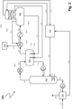
- figure 2 shows a method 200 according to the invention for cleaning crude synthesis gas with methanol as a physically acting absorbent, in which an acid gas containing hydrogen sulfide (H 2 S) is produced, which is fed to a Claus plant for the production of elemental sulfur.
- figure 2 also shows an acid gas separator and its use in the process according to the invention.
- a raw synthesis gas is fed via a line 201 to an absorption device A02 at a pressure of 40 bar, which contains carbon monoxide (CO) and hydrogen (H 2 ) as desired components, and hydrogen sulfide (H 2 S), carbon dioxide (CO 2 ), and hydrogen cyanide (HCN).
- H 2 S, CO 2 and HCN are removed by treatment with cold methanol as absorbent.
- Purified synthesis gas leaves absorption device A02 via a line 202.
- Methanol loaded with H 2 S and CO 2 is drawn off via a line 203 from absorption device A02 and fed to a reabsorber R02.
- methanol laden with HCN and methanol laden with CO 2 are drawn off as further streams from the absorption device.
- HCN-laden methanol also known as prewash methanol
- H02 hot regenerator (not shown).
- CO 2 -loaded methanol after passing through one or more depressurization stages to remove CO 2 (flashing), is also fed to hot regenerator H02.
- hot regenerator H02 by flashing with own steam, regenerated methanol is withdrawn via a line 204 and fed through a pump P02 and a line 217 absorption device A02 for the renewed absorption of undesired components from synthesis gas.
- reabsorber R02 CO 2 is expelled from methanol laden with CO 2 and H 2 S by flashing with nitrogen as the inert gas .
- the hydrogen sulfide that is expelled in the process is also reabsorbed by methanol in reabsorber R02.
- H 2 S-loaded methanol obtained in this way is supplied via a line 219 to the H 2 S hot regenerator H02.
- hot regenerator H02 a gas mixture is obtained by heating (boiling) laden with H 2 S and HCN methanol, which includes methanol vapors, H 2 S and HCN and is drawn off via a line 205 from hot regenerator H02.
- the two-phase mixture of H 2 S, HCN, methanol vapor and liquid methanol resulting from the partial condensation of methanol is fed to a mixing container M02 via a line 206.
- the aforementioned mixture is drawn off via a line 207 from the mixing container M02 and, after further cooling, in an indirect Heat exchangers W12 and an indirect heat exchanger W22 via lines 207, 208 and 209 fed to an acid gas separator S02.
- Acid gas separator S02 has a condensation area KB02 (lower part) and an absorption area AB02 (upper area), where absorption area AB02 has a fixed bed of packing to increase the inner surface.
- the absorption area AB02 and the condensation area SO2 are separated from one another by a gas-permeable floor GB02.
- Gas-permeable floor GB02 is designed as a chimney floor in the example shown.
- the housing part of the absorption section AB02 of sour gas separator S02 is made of a stainless steel, while the housing part of the condensation section KB02 of the sour gas separator S02 is made of low-alloy steel.
- the mixture of methanol, H 2 S and HCN Upon entering acid gas separator S02, the mixture of methanol, H 2 S and HCN has a temperature of around -36 °C.
- the gas phase consisting of H 2 S and HCN is separated from the methanol liquid phase in the condensation area KB02.
- a first resulting acid gas partial flow of H 2 S and HCN is drawn off via line 210 from acid gas separator S02, used to cool the mixture supplied from line 207 in heat exchanger W12 and then via line 211 to a Claus plant CO2 to obtain added elemental sulfur.
- the mixture in line 211 has a temperature of about 25°C.
- a second acid gas partial flow is passed from the condensation area KB02 through gas-permeable tray GB02 from bottom to top over absorption area AB02 of the acid gas separator S02 and HCN is absorbed from the second acid gas partial flow by cryogenic methanol.
- Cryogenic methanol laden with HCN collects as a liquid level (not shown) on gas permeable tray GB02.
- HCN-laden methanol collected on the gas-permeable base GB02 designed as a chimney base is fed to the mixing container M02 via a line 218 and a filler neck ST02.
- the filler neck ST02 is by spacing its end from the housing wall of the Mixing container M02 arranged in such a way that cryogenic methanol laden with HCN does not come into contact with the housing wall of mixing container M02 during the filling process.
- the housing wall of the M02 mixing tank is made of low-alloy steel, while the ST02 filler neck is made of higher-alloy, acid and rust-resistant steel.
- the cryogenic methanol drawn off from the gas-permeable tray GB02 does not come into contact with the HCN gas present in the condensation area KB02 .
- reabsorption of HCN from the second sour gas stream in methanol in the condensation area KB02 of sour gas separator S02 is not possible.
- Cryogenic methanol used for the absorption of HCN in the absorption area AB02 is fed via a line 212 from the reabsorber R02 to the absorption area AB02 of the acid gas separator SO2. It has a temperature of around -63 °C. Acid gas of the second acid gas partial flow freed from HCN and now mainly containing H 2 S is fed via line 213 to reabsorber R02, whereby H 2 S is kept in circulation and can be fed back to hot regenerator H02 with the methanol flow in line 204.
- Condensed methanol from acid gas separator S02 is fed via line 214 to mixing tank M02 via a filler neck ST12 made of stainless steel and mixed there with partially condensed methanol and a gas mixture from line 206, resulting in continuous temperature equalization between the components in mixing tank M02.
- the end of the filler neck ST12 like the end of the filler neck ST02, is at a distance from the wall of the mixing container M02. Due to the temperature equalization effected in mixing tank M02, unintentional outgassing due to heating that is too rapid or uncontrolled does not occur, which could lead to problems when returning the methanol via lines 215 and 216 and the pump P12 can lead to hot regenerator H02.
- Regenerated methanol generated in hot regenerator H02 is withdrawn via line 204 as mentioned above and fed via pump P01 and line 217 to absorption device A01 for renewed absorption of undesired components from synthesis gas.
- the example shows that 14% more NH 3 and 38% more HCN reach the Claus plant as a result of the process according to the invention compared to the known process according to the comparative example. At the same time, the proportion of these substances in the condensed methanol is advantageously reduced by 43% (NH 3 ) and 26% (HCN).
- Embodiments of the invention are described with reference to different types of objects.
- certain embodiments are described with reference to method-type claims, while other embodiments are described with reference to apparatus-type claims.
- a person skilled in the art will appreciate from the above and the following description that, unless otherwise indicated, in addition to any combination of features belonging to one type of claim type, any combination between features relating to different types of subject-matter or claim types is also contemplated can be drawn. All features can be combined to achieve synergistic effects that go beyond the simple summation of technical features.
Landscapes
- Chemical & Material Sciences (AREA)
- Engineering & Computer Science (AREA)
- Chemical Kinetics & Catalysis (AREA)
- General Chemical & Material Sciences (AREA)
- Oil, Petroleum & Natural Gas (AREA)
- Combustion & Propulsion (AREA)
- Organic Chemistry (AREA)
- Analytical Chemistry (AREA)
- Inorganic Chemistry (AREA)
- Health & Medical Sciences (AREA)
- Toxicology (AREA)
- Gas Separation By Absorption (AREA)
Description
- Die Erfindung betrifft ein Verfahren zur Reinigung von Syntheserohgas mit Methanol als physikalisch wirkendem Absorptionsmittel, bei dem ein zumindest Schwefelwasserstoff (H2S) aufweisendes Sauergas erzeugt wird.
- Verfahren zur Abtrennung von unerwünschten Begleitstoffen aus technischen Syntheserohgasen mittels physikalischer oder chemischer Absorption sind aus dem Stand der Technik bekannt. Mit solchen Verfahren können unerwünschte Bestandteile aus durch Vergasung oder Reformierung von kohlenstoffhaltigen Einsatzstoffen erzeugten Syntheserohgasen, beispielsweise Kohlendioxid (CO2) und Schwefelwasserstoff (H2S), aber auch Carbonylsulfid (COS), Mercaptane und Cyanwasserstoff (HCN), von den erwünschten Synthesegasbestandteilen wie Wasserstoff (H2) und Kohlenmonoxid (CO) bis in den Spurenbereich entfernt werden.
- In diesen auch als Gaswäschen bezeichneten Verfahren werden die Eigenschaften von Flüssigkeiten ausgenutzt, gasförmige Stoffe zu absorbieren und physikalisch oder chemisch gebunden in Lösung zu halten. Wie gut ein Gas von einer Flüssigkeit physikalisch absorbiert wird, wird durch den Absorptionskoeffizienten - auch als Löslichkeitskoeffizient bezeichnet - ausgedrückt. Je besser das Gas in der Flüssigkeit absorbiert oder gelöst wird, desto größer ist der Absorptionskoeffizient. Der Absorptionskoeffizient steigt im Allgemeinen mit sinkender Temperatur und, nach dem Gesetz von Henry, mit steigendem Druck. Die in Gaswäschen eingesetzten Flüssigkeiten werden allgemein auch als Waschmittel oder Absorptionsmittel bezeichnet.
- Bei der Gaswäsche aus dem Syntheserohgas ausgewaschene Komponenten werden im Anschluss an die Gaswäsche aus dem beladenen Absorptionsmittel entfernt, wodurch ein regeneriertes oder zumindest teilregeneriertes Absorptionsmittel erhalten wird. Bekannte Verfahren zur Regenerierung des Absorptionsmittels sind Druckentspannung (Flashen) mit oder ohne Stripp-gas sowie Heißregenerierung, bei der der Eigendampf des Absorptionsmittels als Stripp-Gas verwendet wird.
- Ein bekanntes und häufig angewendetes Gaswäscheverfahren ist das Rectisol-Verfahren, das in Ullmann's Encyclopedia of Industrial Chemistry, 6. Aufl. Bd. 15, S. 399 ff. grundsätzlich beschrieben wird. Im Rectisol-Verfahren erfolgt die Aufnahme der oben erwähnten, unerwünschten Bestandteile des Syntheserohgases durch kaltes, das heißt signifikant unter Umgebungstemperatur abgekühltes Methanol als Absorbens oder Absorptionsmittel, wobei in einer Absorptionsvorrichtung, auch als Absorber oder Waschkolonne bezeichnet, ein intensiver Stoffaustausch zwischen dem Syntheserohgas und dem Absorptionsmittel erfolgt. Dabei erhöht sich die Löslichkeit der unerwünschten Gasbestandteile wie oben erwähnt mit sinkender Temperatur des Methanols und zunehmendem Druck, während sie für Wasserstoff und Kohlenmonoxid praktisch konstant bleibt. Methanol hat zudem den Vorteil, selbst bei Temperaturen bis hinab zu -75 °C noch eine geringe Viskosität aufzuweisen, womit es auch bei sehr niedrigen Temperaturen großtechnisch verwendbar ist.
- So beschreibt beispielsweise
WO 2016/120018 A1 ein Verfahren zur Abtrennung unerwünschter, insbesondere acider Gasbestandteile aus einem Rohsynthesegas durch Absorption mit kaltem Methanol als physikalischem Waschmittel, bei dem das Methanol in einer Kompressionskältemaschine unter Verwendung eines Mehrkomponenten-Kühlmittels abgekühlt wird, wobei das Kühlmittel aus einem Propylen und mindestens einen weiteren Stoff umfassenden Stoffgemisch besteht. -
DE 10 2007 052 137 A1 offenbart ein Verfahren zur Waschmittelregenerierung in einer physikalischen Gaswäsche, insbesondere zur Regenerierung von Methanol, wobei aus einem Gasgemisch Schwefelkomponenten (H2S, COS) und Cyanwasserstoff (HCN) durch Methanol ausgewaschen werden, wobei diese Komponenten selektiv aus dem zu regenerierenden Waschmittel abtrennbar sind. -
DE 26 44 323 A1 offenbart ein Verfahren zum Regenerieren von wasserhaltigem Methanol im Rahmen einer Gaswäsche, bei welchem dem Lösungsmittel (Methanol) eine lösliche Substanz zugesetzt wird, welche mit aus dem Gas der Gaswäsche ins Lösungsmittel übergegangenen Metallverbindungen lösliche Komplexverbindungen bildet. Auf diese Weise wird die Bildung unlöslicher Verbindungen, wie beispielsweise die Bildung von Metallsulfiden aus Metallen und Schwefelwasserstoff, verhindert. - Die in Gaswäschen verwendeten Absorptionsvorrichtungen weisen jeweils dedizierte Bereiche oder Stufen zur Entfernung von sauren Gasbestandteilen und weiteren Verunreinigungen auf. Aufgrund der Selektivität des jeweiligen Absorptionsmittels für bestimmte Gasbestandteile werden diese mehr oder weniger leicht absorbiert. Im Beispiel des mit Methanol als Absorptionsmittel arbeitenden Rectisol-Verfahrens werden Spurenbestandteile wie Cyanwasserstoff (HCN) am leichtesten absorbiert, gefolgt von den Schwefelverbindungen Schwefelwasserstoff (H2S), Carbonylsulfid (COS) und Mercaptanen, und schließlich gefolgt von Kohlendioxid (CO2), das im Vergleich zu den vorgenannten Gasen in Bezug auf Methanol den niedrigsten Absorptionskoeffizienten aufweist. Aufgrund dieser Selektivität werden in den dedizierten Bereichen oder Stufen der Absorptionsvorrichtung üblicherweise ein mit hauptsächlich Kohlendioxid beladenes Absorptionsmittel erzeugt, ein mit Schwefelwasserstoff und Kohlendioxid beladenes Absorptionsmittel erzeugt ("Entschwefelung"), sowie ein mit Spurenbestandteilen beladenes Absorptionsmittel erzeugt.
- Bei der Entschwefelung im Rectisol-Verfahren entfernter Schwefelwasserstoff (H2S) wird üblicherweise durch Heißregenerierung des mit H2S beladenen Methanols wieder ausgetrieben. Das dabei erhaltene H2S aufweisende Gas, auch als Sauergas bezeichnet, kann anschließend einer Anlage zur Produktion von elementarem Schwefel nach dem Claus-Verfahren zugeführt werden. Dabei sind an das der Claus-Anlage zugeführte Sauergas bestimmte Anforderungen bezüglich des H2S-Gehalts zu stellen, der im Normalfall 25 mol-% nicht unterschreiten sollte.
- Zur Erreichung eines möglichst hohen H2S-Gehalts im Sauergas kommt im Rahmen des Rectisol-Verfahrens ein sogenannter Reabsorber zum Einsatz. Dem Reabsorber wird zunächst mit H2S und CO2 beladenes Methanol aus der Entschwefelungsstufe der Absorptionsvorrichtung zugeführt. Anschließend wird CO2 durch Druckentspannung und Strippen mit Stickstoff weitgehend vollständig ausgetrieben und als Abgas entfernt. Beim Strippen mitausgetriebener Schwefelwasserstoff wird durch dem Reabsorber zugeführtes Methanol reabsorbiert, wobei aufgrund des größeren Absorptionskoeffizienten von H2S gegenüber CO2 in Methanol im Wesentlichen H2S und CO2 in vernachlässigbaren Mengen reabsorbiert wird. Das den Reabsorber verlassende, mit H2S beladene Methanol wird anschließend einer Heißregenerierung zugeführt, wobei ein als Hauptbestandteil H2S aufweisendes Sauergas erhalten wird. Die Heißregenerierung verlassendes Sauergas weist einen so hohen H2S-Gehalt und einen so niedrigen CO2-Gehalt auf, dass es die Anforderungen für den Claus-Prozess in der Regel erfüllt.
- Die Heißregenerierung verlassendes Sauergas kann nicht unmittelbar dem Claus-Verfahren zugeführt werden. Vielmehr ist das Sauergas in einem dem Claus-Verfahren vorgelagerten Schritt von bei der Heißregenerierung mit ausgetriebenen Methanol-Dämpfen durch Kondensation dieser Dämpfe in einem Sauergas-Abscheider zu befreien. Dadurch wird der H2S-Gehalt im Sauergas auf die erforderliche Menge erhöht. Der Sauergas-Abscheider weist einen Absorptionsbereich sowie zumindest zwei Austrittsöffnungen auf. Die erste Austrittsöffnung dient dem Austritt des Sauergases in Richtung Claus-Anlage. Die zweite Austrittsöffnung dient der Rückführung eines im Absorptionsbereich behandelten Teils des Sauergases zum Reabsorber. Es wird somit ein Teil des dem Sauergasabscheider zugeführten Schwefelwasserstoffs zum Reabsorber zurückgeführt, wodurch im Resultat ein erhöhter Gehalt von Schwefelwasserstoff im Sauergas erreicht wird.
- Der Absorptionsbereich des Sauergas-Abscheiders dient der Entfernung von Spurenkomponenten wie HCN und/oder NH3, welche dafür vorgesehen sind die Gaswäsche-Anlage mit dem Sauergas in Richtung Claus-Anlage zu verlassen. Die vorgenannten Spurenkomponenten sollten nicht in andere Teile der Gaswäsche-Anlage gelangen, um die Kontamination von Synthesegas oder anderen Produkten zu verhindern. HCN weist ferner korrosive Eigenschaften auf, was dazu führen kann, das für bestimmte Anlagenteile ein hochwertiger Stahl als Werkstoff verwendet werden müsste. NH3 entsteht beispielsweise aus HCN im Rahmen einer der Gaswäsche vorgeschalteten Wassergas-Shift-Reaktion (Umsetzung von Kohlenmonoxid mit Wasser zu Wasserstoff und Kohlendioxid) und kann dadurch in Spuren im Syntheserohgas vorhanden sein. Typischerweise wird NH3 in einem Ammoniak-Wäscher mit Wasser als Absorptionsmittel vor der Absorption mit Methanol ausgewaschen. Wird NH3 dabei nicht vollständig entfernt, können sich Reste davon im Kopfbereich des Heißregenerators anreichern. Falls NH3 über den Sauergas-Abscheider in den Reabsorber gelangt, bilden sich dort mit CO2 Ammoniumcarbamat und/oder Ammoniumcarbonat, was zu Verlegungen und Verstopfungen von Bauteilen führen kann. Aus NH3 und H2S bildet sich Ammoniumsulfid, welches sich im Absorptionsmittel anreichert und das Synthesegas verunreinigen kann.
- HCN und/oder NH3 sind somit Komponenten, die zu keinem Zeitpunkt des Verfahrens in den Reabsorber oder andere Anlagenkomponenten gelangen sollten.
- Aus diesem Grund wird/werden HCN und/oder NH3 standardmäßig im Absorptionsbereich des Sauergas-Abscheiders mit Hilfe von tiefkaltem Methanol absorbiert. Das von HCN und/oder NH3 weitgehend befreite Sauergas kann anschließend bedenkenlos zum Reabsorber geleitet werden.
- Im Sauergas-Abscheider werden tiefkaltes Methanol, üblicherweise aus dem Reabsorber, und weniger kaltes, zumindest teilweise kondensiertes Methanol aus dem Heißregenerator zusammengeführt. Aus dem weniger kalten Methanol des Heißregenerators austretender Cyanwasserstoff und/oder Ammoniak kann/können dabei durch das durch die Temperaturdifferenz bedingte besser absorbierende tiefkalte Methanol gelöst werden. Dieser Vorgang führt dazu, dass weniger HCN und/oder NH3 den Sauergas-Abscheider in Richtung Claus-Anlage verlässt/verlassen. Gleichzeitig kommt es zu einer Anreicherung von HCN und/oder NH3 im Kopfbereich des Heißregenerators. Im Sauergas-Abscheider verwendetes tiefkaltes Methanol erfordert ferner, dass damit in Berührung kommende Teile des Sauergas-Abscheiders aus einem hochwertigen Werkstoff, beispielsweise einem rostfreiem Stahl, zu fertigen sind. Dadurch anfallende höhere Werkstoffkosten für den Sauergasabscheider sind zu vermeiden.
- Es ist somit eine Aufgabe der vorliegenden Erfindung ein Verfahren anzugeben, das die vorgenannten Nachteile des Standes der Technik zumindest teilweise überwindet.
- Eine weitere Aufgabe der Erfindung liegt darin ein Verfahren anzugeben, welches die Absorption von HCN und/oder NH3 im Sauergas-Abscheider verbessert, so dass ein möglichst geringer Anteil dieser Substanzen vom Sauergas-Abscheider in den Reabsorber gelangt.
- Eine weitere Aufgabe der Erfindung liegt darin ein Verfahren anzugeben, das den Einsatz von hochwertigen Werkstoffen wie rostfreien Stählen in im Rahmen des Verfahrens verwendeten Bauteilen reduziert.
- Eine weitere Aufgabe der Erfindung liegt darin eine Vorrichtung oder eine Verwendung anzugeben, welche die vorgenannten Aufgaben zumindest teilweise löst.
- Die Aufgaben der Erfindung werden zumindest teilweise gelöst durch ein Verfahren zur Reinigung von Syntheserohgas mit Methanol als physikalisch wirkendem Absorptionsmittel, bei dem ein zumindest Schwefelwasserstoff (H2S) aufweisendes Sauergas erzeugt wird, und das Verfahren folgende Prozessschritte umfasst, wobei die Prozessschritte nicht zwingend in der angegebenen Reihenfolge auszuführen sind:
- Behandeln von zumindest Kohlenmonoxid (CO), Wasserstoff (H2), Schwefelwasserstoff (H2S), sowie Cyanwasserstoff (HCN) und/oder Ammoniak (NH3) aufweisendem Syntheserohgas mit Methanol in einer Absorptionsvorrichtung, wobei ein zumindest mit H2S, sowie HCN und/oder NH3 beladenes Methanol erhalten wird;
- Heißregenerieren des mit H2S, sowie HCN und/oder NH3 beladenen Methanols in einem Heißregenerator, wobei ein zumindest Methanol, H2S, sowie HCN und/oder NH3 aufweisendes Gasgemisch erhalten wird, das aus dem Heißregenerator abgezogen wird;
- Kühlen des aus dem Heißregenerator abgezogenen Gasgemischs und Überführen des gekühlten Gasgemischs in einen Sauergas-Abscheider, wobei der Sauergas-Abscheider einen Absorptionsbereich und einen Kondensationsbereich aufweist, wobei der Absorptionsbereich und der Kondensationsbereich durch einen gasdurchlässigen Boden voneinander separiert sind;
- Kondensieren von Methanol aus dem Gasgemisch im Kondensationsbereich des Sauergas-Abscheiders, Abziehen des kondensierten Methanols aus dem Sauergas-Abscheider und Überführen zum Heißregenerator;
- Abziehen eines H2S, sowie HCN und/oder NH3 aufweisenden ersten Sauergas-Teilstroms aus dem Sauergas-Abscheider;
- Leiten eines H2S, sowie HCN und/oder NH3 aufweisenden zweiten Sauergas-Teilstroms über den Absorptionsbereich des Sauergas-Abscheiders, wobei HCN und/oder NH3 durch dem Absorptionsbereich des Sauergas-Abscheiders zugeführtes tiefkaltes Methanol absorbiert wird, sich mit HCN und/oder NH3 beladenes tiefkaltes Methanol im Bereich des gasdurchlässigen Bodens sammelt und ein zumindest teilweise von HCN und/oder NH3 befreiter zweiter Sauergas-Teilstrom erhalten wird;
- Abziehen des zumindest teilweise von HCN und/oder NH3 befreiten zweiten Sauergas-Teilstroms aus dem Sauergas-Abscheider;
- Abziehen des mit HCN und/oder NH3 beladenen tiefkalten Methanols vom Bereich des gasdurchlässigen Bodens des Sauergas-Abscheiders und Überführen des mit HCN und/oder NH3 beladenen tiefkalten Methanols zum Heißregenerator.
- Unter "physikalisch wirkendem Absorptionsmittel" wird in Zusammenhang mit Gegenständen der Erfindung ein Absorptionsmittel verstanden, bei dem die Löslichkeit des betreffenden Gases im Absorptionsmittel durch physikalische Wechselwirkungen bewirkt wird.
- Unter "Syntheserohgas" wird in Zusammenhang mit Gegenständen der Erfindung ein Synthesegas verstanden, das neben erwünschten Bestanteilen wie Wasserstoff (H2) und Kohlenmonoxid (CO) noch über unerwünschte Bestandteile wie Schwefelwasserstoff (H2S) und Kohlendioxid (CO2) verfügt, von denen es in einem Gaswäscheverfahren zu befreien ist.
- Unter einem "Sauergas" wird in Zusammenhang mit Gegenständen der Erfindung ein Gas oder Gasgemisch verstanden, das zumindest eine in Wasser oder einem anderen geeigneten protischen Lösungsmittel sauer reagierende Komponente aufweist, wie beispielsweise Schwefelwasserstoff (H2S) oder Cyanwasserstoff (HCN). Das Sauergas kann in Zusammenhang mit Gegenständen der Erfindung außer einer oder mehreren sauer reagierenden Komponenten auch eine oder mehrere basisch oder neutral reagierende Komponenten aufweisen. Ein Beispiel für eine basisch reagierende Komponente im Sauergas ist Ammoniak (NH3).
- Unter einem "Sauergas-Abscheider" wird in Zusammenhang mit Gegenständen der Erfindung allgemein eine Vorrichtung zur Abtrennung einer Flüssigkeit aus einem Gemisch verstanden, wobei es sich bei dem Gemisch beispielsweise um ein zweiphasiges Gemisch aus zumindest einem Gas und einer Flüssigkeit handeln kann, beispielsweise ein Aerosol, wobei sich die Vorrichtung zur Abtrennung eines Sauergases aus einem solchen Gemisch eignet.
- Unter einem "Kondensationsbereich" des Sauergas-Abscheiders wird in Zusammenhang mit Gegenständen der Erfindung ein Bereich verstanden, der sich zum Übergang eines in einem Gemisch vorhandenen Stoffes vom gasförmigen in den flüssigen Aggregatzustand eignet.
- Unter einem "Absorptionsbereich" des Sauergas-Abscheiders wird in Zusammenhang mit Gegenständen der Erfindung ein Bereich verstanden, der sich zur Absorption zumindest eines gasförmigen Stoffes in einem geeigneten flüssigen Absorptionsmittel eignet.
- Unter "tiefkaltes Methanol" wird in Zusammenhang mit Gegenständen der Erfindung Methanol verstanden, das eine Temperatur von kleiner oder gleich 0 °C aufweist, oder kleiner gleich -15 °C, oder kleiner gleich -30 °C, oder kleiner gleich -40 °C, oder kleiner gleich -50 °C, oder kleiner gleich -60 °C.
- Unter einem "gasdurchlässigen Boden" wird im Zusammenhang mit Gegenständen der Erfindung ein Boden verstanden, der für gasförmige Substanzen durchlässig ist. Gleichzeitig ist der gasdurchlässige Boden für Flüssigkeiten teilweise oder vollständig nicht durchlässig. Der gasdurchlässige Boden kann in einem Beispiel so konstruiert sein, dass sich eine Flüssigkeitsschicht auf dem gasdurchlässigen Boden bis zu einer bestimmten Menge sammeln kann, so dass der gasdurchlässige Boden in Abhängigkeit seiner Konstruktionsweise zumindest bis zu einem bestimmten Maß für eine Flüssigkeit nicht durchlässig ist. In einem Beispiel ist der gasdurchlässige Boden für eine Flüssigkeit unidirektional undurchlässig, das heißt in einer Richtung ist der gasdurchlässige Boden für eine Flüssigkeit undurchlässig, jedoch in einer anderen, beispielsweise entgegengesetzten Richtung ist der gasdurchlässige Boden für eine Flüssigkeit durchlässig. In einem Beispiel handelt es sich bei dem gasdurchlässigen Boden um einen Boden, der aufgrund seiner makroskopisch-geometrischen Ausgestaltung von einem Gas durchströmt werden kann, auf dem sich aber gleichzeitig eine Schicht einer Flüssigkeit bis zu einer bestimmten Menge sammeln kann, wodurch der Boden für die Flüssigkeit zumindest teilweise nicht durchlässig ist. In einem anderen Beispiel handelt es sich bei dem gasdurchlässigen Boden um einen Boden, der auf mikroskopischer Ebene derart gestaltet ist, dass ein Gas passieren kann, jedoch keine Flüssigkeit. Ein Beispiel für einen solchen Boden ist eine für Gase durchlässige und Flüssigkeiten undurchlässige Membran. Die genannten Beispiele sind nicht in beschränkender Weise zu verstehen, so dass weitere Ausführungsformen gasdurchlässiger Böden denkbar sind.
- Unter einem "Heißregenerator" wird im Zusammenhang mit Gegenständen der Erfindung eine Vorrichtung verstanden, die sich allgemein zur Heißregenerierung beladener Absorptionsmittel eignet, insbesondere zur Heißregenerierung beladener Absorptionsmittel mit Eigendampf des Absorptionsmittels.
- In aus dem Stand der Technik bekannten Verfahren tritt ein vorgekühltes Gemisch aus zumindest teilweise kondensiertem Methanol (zweiphasiges Gemisch aus dampfförmigem und flüssigem Methanol) und Sauergas in den Sauergas-Abscheider ein. Dabei wird HCN und/oder NH3 als Verunreinigung aufweisendes, zumindest H2S aufweisendes Sauergas aus dem Gemisch freigesetzt, welches als erster Teilstrom aus dem Sauergas-Abscheider austritt. Gleichzeitig wird ein zweiter Teilstrom des Sauergases über den Absorptionsbereich des Sauergas-Abscheiders geleitet und tritt nach Absorption von Verunreinigungen wie HCN und/oder NH3 aus dem Sauergas-Abscheider aus, um beispielsweise in einem weiteren Schritt einer Konzentrierung von H2S zugeführt zu werden. Im zweiten Teilstrom vorhandene Verunreinigungen wie HCN und/oder NH3 werden im Absorptionsbereich des Sauergas-Abscheiders durch tiefkaltes Methanol entfernt. Dabei werden durch die niedrige Temperatur des tiefkalten Methanols in nachteiliger Weise auch aus dem ersten Teilstrom ausgasende Verunreinigungen absorbiert, die sich anschließend beispielsweise im Kopfbereich des Heißregenerators anreichern können.
- Durch die erfindungsgemäße Verfahrensführung, bei der der Kondensationsbereich und der Absorptionsbereich des Sauergas-Abscheiders durch einen gasdurchlässigen Boden voneinander separiert sind, wird der vorgenannte Nachteil eliminiert. Der gasdurchlässige Boden verhindert, dass tiefkaltes Methanol mit aus dem ersten Teilstrom ausgasenden Verunreinigungen wie HCN und/oder NH3 in Kontakt kommt. Vielmehr wird im Bereich des gasdurchlässigen Bodens angesammeltes tiefkaltes Methanol, welches ausschließlich Verunreinigungen wie HCN und/oder NH3 aus dem zweiten Teilstrom aufweist, vom gasdurchlässigen Boden abgezogen und anschließend in den Heißregenerator zurückgeführt. Ein Kontakt zwischen dem tiefkalten Methanol und den Gasen des ersten Teilstroms ist somit nicht möglich, wodurch Verunreinigungen wie HCN und/oder NH3 aus dem ersten Teilstrom in vorteilhafter Weise nicht durch tiefkaltes Methanol absorbiert werden. Im Resultat unterbleibt eine Anreicherung von durch zusätzlich aus dem ersten Teilstrom absorbierten Verunreinigungen wie HCN und/oder NH3 im Heißregenerator oder anderen Anlagenteilen.
- Eine bevorzugte Ausführungsform des erfindungsgemäßen Verfahrens ist dadurch gekennzeichnet, dass das kondensierte Methanol und das mit HCN und/oder NH3 beladene tiefkalte Methanol als getrennte Ströme einem Mischbehälter zugeführt werden, und nach Mischen im Mischbehälter zum Heißregenerator zurückgeführt werden.
- Der Begriff "Mischbehälter" bedeutet im Zusammenhang mit Gegenständer der Erfindung, dass im Mischbehälter eine zumindest teilweise Durchmischung der dem Mischbehälter zugeführten Fluide stattfindet. Die Durchmischung wird in einem Beispiel durch Diffusion und/oder Konvektion bewirkt. In einem weiteren Beispiel wird die Durchmischung zusätzlich oder stattdessen durch einen statischen und/oder einen aktiven Mischer bewirkt. Dabei sind die Arten der Durchmischung nicht auf die genannten Beispiele beschränkt.
- Im Mischbehälter findet eine Angleichung der Temperaturen des vom gasdurchlässigen Boden abgezogenen tiefkalten Methanols aus dem Absorptionsbereich und des kondensierten Methanols aus dem Kondensationsbereich des Sauergas-Abscheiders statt.
- Bevorzugt wird dabei auch das aus dem Heißregenerator abgezogene Gasgemisch dem Mischbehälter zugeführt, und im Mischbehälter mit dem kondensierten Methanol sowie dem mit HCN und/oder NH3 beladenen tiefkalten Methanol zusammengeführt, wobei Methanol aus dem Gasgemisch zumindest teilweise kondensiert, wodurch ein Zweiphasen-Gemisch erhalten wird, und das zumindest teilweise kondensiertes Methanol enthaltende Zweiphasen-Gemisch anschließend dem Sauergas-Abscheider zugeführt.
- Das Zweiphasen-Gemisch weist dampfförmiges und gasförmiges Methanol sowie Sauergase auf. Zum weiter verbesserten Ausgleich von Temperaturunterschieden findet im Mischbehälter eine Mischung mit dem aus dem Heißregenerator abgezogenen Gasgemisch und den aus dem Sauergasabscheider abgezogenen Strömen statt. Dadurch wird in vorteilhafter Weise ein unbeabsichtigtes Austreten von Gasen aus kondensiertem Methanol verhindert. Aus kondensiertem Methanol austretende Gase können beispielsweise Probleme in der für die Rückführung des im Sauergasabscheiders kondensierten Methanols zum Heißregenerator bereiten. Durch den zwischen Heißregenerator und Sauergas-Abscheider geschalteten Mischbehälter und den im Mischbehälter kontinuierlich ablaufenden Mischvorgang wird ein solches Ausgasen effektiv verhindert und gleichzeitig ein Temperaturausgleich zwischen den einzelnen Strömen geschaffen, ohne dass zusätzliche Wärmeaustauscher erforderlich wären.
- Eine bevorzugte Ausführungsform des erfindungsgemäßen Verfahrens ist dadurch gekennzeichnet, dass der zumindest teilweise von HCN und/oder NH3 befreite zweite Sauergas-Teilstrom einem Reabsorber zur Reabsorption von im von HCN und/oder NH3 zumindest teilweise befreiten zweiten Sauergas-Teilstrom enthaltenen H2S zugeführt wird, wobei im Reabsorber mit H2S beladenes Methanol erhalten wird.
- Der Reabsorber hat vornehmlich die Funktion, aus einem aus der Absorptionsvorrichtung abgezogenen, mit Schwefelwasserstoff (H2S) und Kohlendioxid (CO2) beladenen Methanol-Strom durch Strippen mit einem Inertgas zunächst Kohlendioxid auszutreiben und dabei ungewollt mitausgetriebenen Schwefelwasserstoff in tiefkaltem Methanol zu reabsorbieren. Durch Zuführen des zweiten Sauergas-Teilstroms zum Reabsorber findet eine weitere Konzentrierung von H2S statt, so dass das im Heißregenerator erzeugte Sauergas im Ergebnis über einen höheren H2S-Gehalt verfügt.
- In einem weiteren Beispiel ist bevorzugt, dass das im Reabsorber erhaltene, mit H2S beladene Methanol dem Heißregenerator zugeführt wird.
- Eine bevorzugte Ausführungsform des erfindungsgemäßen Verfahrens ist dadurch gekennzeichnet, dass das tiefkalte Methanol dem Absorptionsbereich des Sauergas-Abscheiders aus dem Reabsorber zugeführt wird.
- Das im Reabsorber zirkulierende Methanol verfügt über eine geeignet tiefe Temperatur und Beladung mit H2S, um sowohl Verunreinigungen wie HCN und/oder NH3 als auch H2S aus dem zweiten Teilstrom effektiv absorbieren zu können.
- Eine bevorzugte Ausführungsform des erfindungsgemäßen Verfahrens ist dadurch gekennzeichnet, dass das tiefkalte Methanol eine Temperatur von kleiner oder gleich -40 °C aufweist, bevorzugt kleiner oder gleich -50 °C, besonders bevorzugt von kleiner oder gleich -60 °C.
- Je tiefer die Temperatur des tiefkalten Methanols, desto effektiver die Absorption von Verunreinigungen wie HCN und/oder NH3 aus dem zweiten Teilstrom des Sauergases. Dabei hat sich ein Temperaturbereich zwischen -40 °C und -75 °C als besonders vorteilhaft erwiesen, da einerseits eine hohe Absorptionswirkung besteht, andererseits die hydrodynamischen Eigenschaften des Methanols aufgrund der bis -75 °C relativ niedrigen dynamischen Viskosität bei der großtechnischen Verwendung von Vorteil sind. Besonders bevorzugt weist das tiefkalte Methanol einen Temperaturbereich zwischen -60 °C und -65 °C auf. Je kälter das für die Absorption verwendete Methanol ist, desto besser sind dessen Eigenschaften als Absorptionsmittel.
- Eine bevorzugte Ausführungsform des erfindungsgemäßen Verfahrens ist dadurch gekennzeichnet, dass der erste Sauergas-Teilstrom einer Claus-Anlage zur Herstellung von Schwefel zugeführt wird.
- Im Ergebnis wird durch das erfindungsgemäße Verfahren ein Sauergas erzeugt, das über einen zur Verwendung in einer Claus-Anlage ausreichenden Schwefel-Anteil verfügt. Dabei wird der Schwefel-Anteil nicht ausschließlich durch den im Sauergas enthaltenen Schwefelwasserstoff bestimmt, sondern ferner durch in Methanol absorbierte Mercaptane (Thiole) sowie Carbonylsulfid (COS) und gegebenenfalls weitere Schwefelverbindungen.
- Eine bevorzugte Ausführungsform des erfindungsgemäßen Verfahrens ist dadurch gekennzeichnet, dass der Mischbehälter über mindestens einen Einfüllstutzen zum Zuführen des mit HCN und/oder NH3 beladenen tiefkalten Methanols und/oder des kondensierten Methanols verfügt, wobei ein Ende des Einfüllstutzens so von einer Gehäusewand des Mischbehälters beabstandet ist, dass das mit HCN und/oder NH3 beladene tiefkalte Methanol und/oder das kondensierte Methanol beim Einfüllvorgang nicht in unmittelbaren Kontakt mit der Gehäusewand des Mischbehälters kommt oder kommen.
- Der Mischbehälter verfügt über zumindest einen Einfüllstutzen zum Zuführen des mit HCN und/oder NH3 beladenen tiefkalten Methanols und/oder des kondensierten Methanols zum Mischbehälter, wobei die getrennten Ströme entweder über einen gemeinsamen Einfüllstutzen dem Mischbehälter zugeführt werden oder jeder Strom über wenigstens einen dedizierten Einfüllstutzen zugeführt wird. Im Mischbehälter findet eine Mischung des mit HCN und/oder NH3 beladenen tiefkalten Methanol und des kondensierten Methanols mit aus dem Heißregenerator zugeführten, deutlich wärmerem zumindest Methanol, H2S, sowie HCN und/oder NH3 aufweisendes Gasgemischs statt. Da insbesondere auf sehr niedrige Temperaturen heruntergekühltes, beladenes Methanol das Material des Mischbehälters durch Korrosion schädigen kann, ist es von Vorteil den Einfüllstutzen so anzuordnen, dass beim Einfüllvorgang kein Kontakt zwischen kaltem Methanol und Mischbehälter besteht. Unmittelbar nach dem Einfüllen des mit HCN und/oder NH3 beladenen tiefkalten Methanol und des kondensierten Methanols wird dieses durch mit zumindest Methanol, H2S, sowie HCN und/oder NH3 aufweisendem Gasgemischs aus dem Heißregenerator gemischt und dadurch erwärmt, wodurch eine korrosive Schädigung weniger wahrscheinlich ist.
- Bevorzugt weist das Gehäuse des Mischbehälters einen nicht legierten oder niedrig legierten Stahl als Werkstoff auf, wobei ein nicht legierter Stahl weiter bevorzugt ist.
- Dies wird durch die entsprechende Anordnung der Einfüllstutzen ermöglicht, bei der der oder die Einfüllstutzen so von einer Gehäusewand des Mischbehälters beabstandet ist oder sind, dass das mit HCN und/oder NH3 beladene tiefkalte Methanol und/oder das kondensierte Methanol beim Einfüllvorgang nicht in unmittelbaren Kontakt mit der Gehäusewand des Mischbehälters kommt oder kommen. Es ist somit nicht erforderlich, das Gehäuse des Mischbehälters aus einem hochwertigen Stahl zu fertigen.
- Unter einem "nicht legierten Stahl" wird im Zusammenhang mit Gegenständen der Erfindung ein Stahl verstanden, der keine absichtlich zugegebenen Legierungselemente enthält. Kohlenstoff gilt nicht als Legierungselement. Stahlbegleiter wie Silizium und Mangan in natürlichen, nicht absichtlich legierten Mengen können im nicht legierten Stahl enthalten sein.
- Unter einem "niedriglegierten Stahl" wird im Zusammenhang mit Gegenständen der Erfindung ein Stahl verstanden, der absichtlich legierte Bestandteile enthält, aber nur in niedrigen Gehalten. Insbesondere enthält ein niedriglegierter Stahl kein Legierungselement mit einem Gehalt von mehr als fünf Gew.-%.
- Eine bevorzugte Ausführungsform des erfindungsgemäßen Verfahrens ist dadurch gekennzeichnet, dass der Einfüllstutzen einen säure- und rostbeständigen Stahl als Werkstoff aufweist.
- Da der Einfüllstutzen des Mischbehälters in Kontakt mit HCN und/oder NH3 beladene tiefkalte Methanol und/oder kondensiertem Methanol steht, weist dieser in vorteilhafter Weise einen säure- und rostbeständigen Stahl als Werkstoff auf. In einem weiteren bevorzugten Beispiel weist ausschließlich der Einfüllstutzen des Mischbehälters, als einziges Bauteil des Mischbehälters, einen säure- und rostbeständigen Stahl als Werkstoff auf. Andere Teile des Mischbehälters, vorzugsweise mit Methanol in Kontakt stehende Teile, weisen keinen säure- und rostbeständigen Stahls als Werkstoff auf. Vorzugsweise weisen diese Teile einen nicht legierten oder niedrig legierten Stahl als Werkstoff auf, vorzugsweise einen nicht legierten Stahl.
- Unter einem "säure- und rostbeständigen Stahl" wird in Zusammenhang mit Gegenständen der Erfindung ein Stahl verstanden, der durch entsprechende Legierungszusätze eine schützende Oxidschichten ausbildet, die den Stahl vor Säurekorrosion und/oder Sauerstoffkorrosion schützt. Insbesondere weist ein säurebeständiger oder nichtrostender Stahl einen Legierungsanteil von wenigstens 10,5 Gew.-% Chrom auf, vorzugsweise wenigstens 13 Gew.-% Chrom. Vorzugsweise enthält ein säure- und rostbeständiger Stahl ferner wenigstens ein Element ausgewählt aus der Gruppe umfassend Nickel, Molybdän, Titan und Stickstoff als weiteren Legierungsbestandteil oder weitere Legierungsbestandteile.
- Weiter offenbart (nicht erfindungsgemäss) ist ein Sauergas-Abscheider zur Abscheidung eines zumindest Schwefelwasserstoff (H2S) aufweisenden Sauergases aus einem Gasgemisch, aufweisend einen Absorptionsbereich und einen Kondensationsbereich, wobei der Absorptionsbereich und der Kondensationsbereich durch einen gasdurchlässigen Boden voneinander separiert sind;
- Mittel zum Zuführen eines zumindest Methanol, H2S, sowie HCN und/oder NH3 aufweisenden Gasgemischs zum Kondensationsbereich des Sauergas-Abscheiders zur Kondensation von Methanol aus dem Gasgemisch im Kondensationsbereich des Sauergas-Abscheiders;
- Mittel zum Abziehen eines H2S, sowie HCN und/oder NH3 aufweisenden ersten Sauergas-Teilstroms aus dem Sauergas-Abscheider;
- Mittel zur Absorption von HCN und/oder NH3 aus einem H2S, sowie HCN und/oder NH3 aufweisenden zweiten Sauergas-Teilstrom im Absorptionsbereich des Sauergas-Abscheiders;
- Mittel zum Abziehen eines zumindest teilweise von HCN und/oder NH3 befreiten zweiten Sauergas-Teilstroms aus dem Sauergas-Abscheider;
- Mittel zum Zuführen von tiefkaltem Methanol zum Absorptionsbereich des Sauergas-Abscheiders zur Absorption von HCN und/oder NH3 in tiefkaltem Methanol im Absorptionsbereich des Sauergas-Abscheiders;
- Mittel zum Abziehen eines mit HCN und/oder NH3 beladenen tiefkalten Methanols aus dem Absorptionsbereich des Sauergas-Abscheiders;
- Mittel zum Abziehen von kondensiertem Methanol aus dem Kondensationsbereich des Sauergas-Abscheiders.
- Eine bevorzugte Ausführungsform des Sauergas-Abscheiders ist dadurch gekennzeichnet, dass der Kondensationsbereich und der Absorptionsbereich in ein einziges gemeinsames Gehäuse des Sauergas-Abscheiders integriert sind.
- Dadurch ist eine platzsparende Anordnung innerhalb einer Gaswäsche-Anlage möglich, ohne dass zusätzliche Leitungen zwischen Kondensationsbereich und Absorptionsbereich erforderlich sind. Der gasdurchlässige Boden sorgt für eine ausreichende räumliche Trennung von Kondensationsbereich und Absorptionsbereich, so dass eine Integration beider Bereiche in ein Gehäuse möglich ist, ohne dass aus dem ersten Sauergas-Teilstrom ausgasende Verunreinigungen wie HCN und/oder NH3 in den Absorptionsbereich gelangen und dort durch tiefkaltes Methanol absorbiert werden können.
- Eine bevorzugte Ausführungsform des Sauergas-Abscheiders ist dadurch gekennzeichnet, dass zumindest ein Gehäuseteil des Absorptionsbereichs des Sauergas-Abscheiders einen rostbeständigen oder säurebeständigen Stahl als Werkstoff aufweist und/oder dass zumindest ein Gehäuseteil des Kondensationsbereichs des Sauergas-Abscheiders einen nicht legierten oder niedrig legierten Stahl als Werkstoff aufweist, vorzugsweise einen nicht legierten Stahl.
- Da vornehmlich der Absorptionsbereich des Sauergas-Abscheiders sehr niedrigen Temperaturen durch tiefkaltes Methanol ausgesetzt ist, ist es ausreichend und von Vorteil ausschließlich den Absorptionsbereich des Sauergas-Abscheiders mit einem hochwertigen Werkstoff wie einem rostbeständigen oder säurebeständigen Stahl auszurüsten. Für den Kondensationsbereich, der weniger niedrigen Temperaturen ausgesetzt ist, ist es ausreichend einen nicht legierten oder niedrig legierten Stahl als Werkstoff zu verwenden.
- Eine bevorzugte Ausführungsform des Sauergas-Abscheiders ist dadurch gekennzeichnet, dass der gasdurchlässige Boden als Kaminboden ausgestaltet ist.
- Ein als Kaminboden ausgestalteter gasdurchlässiger Boden ist von unten nach oben durch das Gasgemisch des zweiten Sauergas-Teilstroms durchströmbar. Oberhalb des Kaminbodens werden Bestandteile aus dem zweiten Sauergas-Teilstrom wie HCN und/oder NH3 durch tiefkaltes Methanol absorbiert und können sich auf dem Kaminboden im Absorptionsbereich sammeln. Das mit Verunreinigungen aus dem zweiten Sauergas-Teilstrom wie HCN und/oder NH3 beladene tiefkalte Methanol ist über eine Leitung vom Kaminboden abziehbar, ohne dass dieses anschließend in Kontakt mit den Gasen des ersten Sauergas-Teilstroms treten könnte.
- Eine bevorzugte Ausführungsform des Sauergas-Abscheiders ist dadurch gekennzeichnet, dass der Absorptionsbereich des Sauergas-Abscheiders ein Festbett aufweist. In einem bevorzugten Beispiel weist das Festbett eine Füllkörper-Schüttung zur Oberflächenvergrößerung des Absorptionsbereichs auf. Dadurch wird die Effizienz bei der Absorption der Verunreinigungen aus dem zweiten Sauergas-Teilstrom erhöht.
- Weitere Merkmale, Vorteile und Anwendungsmöglichkeiten der Erfindung ergeben sich auch aus der nachfolgenden Beschreibung eines Ausführungs- und Zahlenbeispiels und der Zeichnungen. Dabei bilden alle beschriebenen und/oder bildlich dargestellten Merkmale für sich oder in beliebiger Kombination den Gegenstand der Erfindung, unabhängig von ihrer Zusammenfassung in den Ansprüchen oder deren Rückbeziehung.
- Es zeigen
- Figur 1
- ein schematisch dargestelltes Fließbild eines aus dem Stand der Technik bekannten Verfahrens und einer Anlage zur Reinigung von Syntheserohgas mit Erzeugung eines Sauergases sowie
- Figur 2
- ein schematisches dargestelltes Fließbild eines erfindungsgemäßen Verfahrens und einer Anlage zur Reinigung von Syntheserohgas mit Erzeugung eines Sauergases unter Verwendung eines Sauergas-Abscheiders.
-
Figur 1 zeigt ein Verfahren bzw. eine Anlage 100 zur Reinigung von Syntheserohgas mit Methanol als physikalisch wirkendem Absorptionsmittel, bei dem ein Schwefelwasserstoff (H2S) aufweisendes Sauergas erzeugt wird, welches einer Claus-Anlage zur Herstellung von elementarem Schwefel zugeführt wird. - Über eine Leitung 101 wird einer Absorptionsvorrichtung A01 bei einem Druck von 40 bar ein Rohsynthesegas zugeführt, welches als erwünschte Bestandteile Kohlenmonoxid (CO) und Wasserstoff (H2), sowie als unerwünschte zu entfernende Bestandteile Schwefelwasserstoff (H2S), Kohlendioxid (CO2), sowie Cyanwasserstoff (HCN) aufweist. In Absorptionsvorrichtung A01 werden H2S, CO2 und HCN durch Behandlung mit kaltem Methanol als Absorptionsmittel entfernt. Gereinigtes Synthesegas verlässt Absorptionsvorrichtung A01 über eine Leitung 102. Mit H2S und CO2 beladenes Methanol wird über eine Leitung 103 aus Absorptionsvorrichtung A01 abgezogen und einem Reabsorber R01 zugeführt. Ferner werden mit HCN beladenes Methanol sowie mit CO2 beladenes Methanol als weitere Ströme aus Absorptionsvorrichtung abgezogen. HCN beladenes Methanol, auch prewash Methanol genannt, wird dabei direkt dem Heißregenerator H01 zugeführt (nicht gezeigt). CO2 beladenes Methanol wird nach Durchlaufen einer oder mehrerer Druckentspannungsstufen zur Entfernung von CO2 (Flashen) ebenfalls Heißregenerator H01 zugeführt (nicht gezeigt). In Heißregenerator H01 durch Flashen mit Eigendampf regeneriertes Methanol wird über eine Leitung 104 abgezogen und durch eine Pumpe P01 sowie eine Leitung 117 Absorptionsvorrichtung A01 zur erneuten Absorption von unerwünschten Bestandteilen aus Synthesegas zugeführt.
- In Reabsorber R01 wird aus CO2 und H2S beladenem Methanol durch Flashen mit Stickstoff als Inertgas CO2 ausgetrieben. Dabei mitausgetriebener Schwefelwasserstoff wird ebenfalls in Reabsorber R01 durch Methanol reabsorbiert. Dabei erhaltenes, mit H2S beladenes Methanol wird über eine Leitung 118 Heißregenerator H01 zur Entfernung von H2S zugeführt. In Heißregenerator H01 wird durch Erhitzen (Aufkochen) von mit H2S und HCN beladenem Methanol ein Gasgemisch erhalten, das Methanol-Dämpfe, H2S sowie HCN umfasst und über eine Leitung 105 aus Heißregenerator H01 abgezogen wird. Nach Kühlen des aus Heißregenerator H01 abgezogenen Gasgemischs in einem Wärmetauscher W01 auf circa 40 °C wird das durch Teilkondensation von Methanol nun zweiphasige Gemisch aus H2S, HCN, Methanol-Dampf und flüssigem Methanol einem Mischbehälter M01 über eine Leitung 106 zugeführt. Vorgenanntes Gemisch wird über eine Leitung 107 aus Mischbehälter M01 abgezogen und nach weiterer Kühlung in einem indirekten Wärmetauschern W11 und einem indirekten Wärmetauscher W21 über die Leitungen 107, 108 und 109 einem Sauergasabscheider S01 zugeführt. Sauergasabscheider S01 verfügt über einen Kondensationsbereich KB01 (unterer Teil) und einen Absorptionsbereich AB01 (oberer Bereich), wobei Absorptionsbereich AB01 ein Festbett aus Füllkörpern zur Vergrößerung der inneren Oberfläche aufweist. Bei Eintritt in Sauergasabscheider S01 weist das Gemisch aus Methanol, H2S und HCN eine Temperatur von circa -36 °C auf. In Sauergasabscheider S01 wird die Gasphase aus H2S und HCN im Kondensationsbereich KB01 von der Methanol-Flüssigphase getrennt. Ein erster dabei erhaltener Sauergas-Teilstrom aus H2S und HCN wird über eine Leitung 110 aus Sauergasabscheider S01 abgezogen, zur Kühlung des aus der Leitung 107 zugeführten Gemischs in Wärmetauscher W11 verwendet und darauffolgend über eine Leitung 111 einer Claus-Anlage C01 zur Gewinnung von elementarem Schwefel zugeführt. Das Gemisch in Leitung 111 weist eine Temperatur von circa 25 °C auf.
- Ein zweiter Sauergas-Teilstrom wird über Absorptionsbereich AB01 des SauergasAbscheiders S01 geleitet und dabei HCN aus dem zweiten Sauergas-Teilstrom durch tiefkaltes Methanol absorbiert. Tiefkaltes Methanol wird über eine Leitung 112 aus Reabsorber R01 dem Absorptionsbereich AB01 des Sauergasabscheiders S01 zugeführt und weist eine Temperatur von circa -63 °C auf. Von HCN befreites, nunmehr hauptsächlich H2S aufweisendes Sauergas des zweiten Sauergas-Teilstroms wird über eine Leitung 113 Reabsorber R01 zugeführt, wodurch H2S im Kreislauf gehalten und mit dem Methanol-Strom in Leitung 104 erneut Heißregenerator H01 zugeführt werden kann.
- Kondensiertes Methanol aus Sauergas-Abscheider S01 wird über eine Leitung 114 Mischbehälter M01 zugeführt und dort mit teilweise kondensiertem Methanol sowie Gasgemisch aus Leitung 106 zusammengeführt und dabei zumindest teilweise vermischt, wodurch ein kontinuierlicher Temperaturausgleich zwischen den in Mischbehälter M01 befindlichen Komponenten erfolgt. Durch den in Mischbehälter M01 bewirkten Temperaturausgleich kommt es nicht zu unbeabsichtigten Ausgasungen durch zu schnelles oder unkontrolliertes Erwärmen, was zu Problemen bei der Rückführung des Methanols über die Leitungen 115 und 116 sowie Pumpe P11 zu Heißregenerator H01 führen kann. In Heißregenerator H01 erzeugtes regeneriertes Methanol wird wie vorgenannt über Leitung 104 abgezogen und über Pumpe P01 sowie Leitung 117 Absorptionsvorrichtung A01 zur erneuten Absorption von unerwünschten Bestandteilen aus Synthesegas zugeführt.
- Im Verfahren gemäß
Figur 1 tritt in Sauergas-Abscheider S01 das Problem auf, dass aus Reabsorber R01 über Leitung 112 zugeführtes, auf -63 °C gekühltes Methanol auch HCN aus dem ersten Sauergas-Teilstrom absorbieren kann. Dieses HCN-Gas ist jedoch für den Ausgang in Richtung Claus-Anlage bestimmt. Aus diesem Grund kann es in nachteiliger Weise zu Anreicherungen von HCN im Heißregenerator H01 und weiteren bereits genannten Problemen kommen. -
Figur 2 zeigt ein erfindungsgemäßes Verfahren 200 zur Reinigung von Syntheserohgas mit Methanol als physikalisch wirkendem Absorptionsmittel, bei dem ein Schwefelwasserstoff (H2S) aufweisendes Sauergas erzeugt wird, welches einer Claus-Anlage zur Herstellung von elementarem Schwefel zugeführt wird.Figur 2 zeigt ferner einen Sauergas-Abscheider und dessen Verwendung im erfindungsgemäßen Verfahren. - Über eine Leitung 201 wird einer Absorptionsvorrichtung A02 bei einem Druck von 40 bar ein Rohsynthesegas zugeführt, welches als erwünschte Bestandteile Kohlenmonoxid (CO) und Wasserstoff (H2), sowie als unerwünschte zu entfernende Bestandteile Schwefelwasserstoff (H2S), Kohlendioxid (CO2), sowie Cyanwasserstoff (HCN) aufweist. In Absorptionsvorrichtung A02 werden H2S, CO2 und HCN durch Behandlung mit kaltem Methanol als Absorptionsmittel entfernt. Gereinigtes Synthesegas verlässt Absorptionsvorrichtung A02 über eine Leitung 202. Mit H2S und CO2 beladenes Methanol wird über eine Leitung 203 aus Absorptionsvorrichtung A02 abgezogen und einem Reabsorber R02 zugeführt. Ferner werden mit HCN beladenes Methanol sowie mit CO2 beladenes Methanol als weitere Ströme aus Absorptionsvorrichtung abgezogen. HCN beladenes Methanol, auch prewash Methanol genannt, wird dabei direkt dem Heißregenerator H02 zugeführt (nicht gezeigt). CO2 beladenes Methanol wird nach Durchlaufen einer oder mehrerer Druckentspannungsstufen zur Entfernung von CO2 (Flashen) ebenfalls Heißregenerator H02 zugeführt. In Heißregenerator H02 durch Flashen mit Eigendampf regeneriertes Methanol wird über eine Leitung 204 abgezogen und durch eine Pumpe P02 sowie eine Leitung 217 Absorptionsvorrichtung A02 zur erneuten Absorption von unerwünschten Bestandteilen aus Synthesegas zugeführt.
- In Reabsorber R02 wird aus CO2 und H2S beladenem Methanol durch Flashen mit Stickstoff als Inertgas CO2 ausgetrieben. Dabei mitausgetriebener Schwefelwasserstoff wird ebenfalls in Reabsorber R02 durch Methanol reabsorbiert. Dabei erhaltenes, mit H2S beladenes Methanol wird über eine Leitung 219 Heißregenerator H02 zur Entfernung von H2S zugeführt. In Heißregenerator H02 wird durch Erhitzen (Aufkochen) von mit H2S und HCN beladenem Methanol ein Gasgemisch erhalten, das Methanol-Dämpfe, H2S sowie HCN umfasst und über eine Leitung 205 aus Heißregenerator H02 abgezogen wird. Nach Kühlen des aus Heißregenerator H02 abgezogenen Gasgemischs in einem Wärmetauscher W02 auf circa 40 °C wird das durch Teilkondensation von Methanol nun zweiphasige Gemisch aus H2S, HCN, Methanol-Dampf und flüssigem Methanol einem Mischbehälter M02 über eine Leitung 206 zugeführt. Vorgenanntes Gemisch wird über eine Leitung 207 aus Mischbehälter M02 abgezogen und nach weiterer Kühlung in einem indirekten Wärmetauschern W12 und einem indirekten Wärmetauscher W22 über die Leitungen 207, 208 und 209 einem Sauergasabscheider S02 zugeführt.
- Sauergasabscheider S02 verfügt über einen Kondensationsbereich KB02 (unterer Teil) und einen Absorptionsbereich AB02 (oberer Bereich), wobei Absorptionsbereich AB02 ein Festbett aus Füllkörpern zur Vergrößerung der inneren Oberfläche aufweist. Absorptionsbereich AB02 und Kondensationsbereich S02 sind erfindungsgemäß durch einen gasdurchlässigen Boden GB02 voneinander separiert. Gasdurchlässiger Boden GB02 ist im gezeigten Beispiel als Kaminboden ausgestaltet. Das Gehäuseteil des Absorptionsbereichs AB02 von Sauergas-Abscheider S02 ist aus einem rostbeständigen Stahl gefertigt, während das Gehäuseteil des Kondensationsbereichs KB02 des Sauergas-Abscheiders S02 aus einem niedriglegierten Stahl gefertigt ist.
- Bei Eintritt in Sauergasabscheider S02 weist das Gemisch aus Methanol, H2S und HCN eine Temperatur von circa -36 °C auf. In Sauergasabscheider S02 wird die Gasphase aus H2S und HCN im Kondensationsbereich KB02 von der Methanol-Flüssigphase getrennt. Ein erster dabei erhaltener Sauergas-Teilstrom aus H2S und HCN wird über eine Leitung 210 aus Sauergasabscheider S02 abgezogen, zur Kühlung des aus der Leitung 207 zugeführten Gemischs in Wärmetauscher W12 verwendet und darauffolgend über eine Leitung 211 einer Claus-Anlage CO2 zur Gewinnung von elementarem Schwefel zugeführt. Das Gemisch in Leitung 211 weist eine Temperatur von circa 25 °C auf.
- Ein zweiter Sauergas-Teilstrom wird vom Kondensationsbereich KB02 durch gasdurchlässigen Boden GB02 hindurch von unten nach oben über Absorptionsbereich AB02 des Sauergas-Abscheiders S02 geleitet und dabei HCN aus dem zweiten Sauergas-Teilstrom durch tiefkaltes Methanol absorbiert. Tiefkaltes, mit HCN beladenes Methanol sammelt sich als Flüssigkeitsstand (nicht gezeigt) auf gasdurchlässigem Boden GB02. Auf dem als Kaminboden ausgestalteten gasdurchlässigen Boden GB02 gesammeltes, mit HCN beladenes Methanol, wird über eine Leitung 218 und einen Einfüllstutzen ST02 Mischbehälter M02 zugeführt. Dabei ist Einfüllstutzen ST02 durch Beabstandung seines Endes von der Gehäusewand des Mischbehälters M02 derart angeordnet, dass tiefkaltes mit HCN beladenes Methanol während des Einfüllvorgangs nicht in Kontakt mit der Gehäusewand von Mischbehälter M02 kommt. Die Gehäusewand von Mischbehälter M02 ist aus einem niedriglegierten Stahl gefertigt, während Einfüllstutzen ST02 aus einem höher legierten, säure- und rostbeständigen Stahl gefertigt ist. Durch Anordnung des gasdurchlässigen Bodens GB02 in Sauergas-Abscheider S02 und die Rückführung von HCN beladenem Methanol über Leitung 218 sowie Einfüllstutzen ST02 in Mischbehälter M02 und anschließend Heißregenerator H02 kommt vom gasdurchlässigen Boden GB02 abgezogenes tiefkaltes Methanol nicht in Kontakt mit im Kondensationsbereich KB02 vorhandenem HCN-Gas. Dadurch ist eine Reabsorption von HCN aus dem zweiten Sauergas-Strom in Methanol im Kondensationsbereich KB02 von Sauergas-Abscheider S02 nicht möglich. Im Resultat findet keine Anreicherung von HCN in Heißregenerator H02 oder anderen Bauteilen der Gaswäsche-Anlage statt.
- Zur Absorption von HCN in Absorptionsbereich AB02 verwendetes tiefkaltes Methanol wird über eine Leitung 212 aus Reabsorber R02 dem Absorptionsbereich AB02 des Sauergasabscheiders S02 zugeführt. Es weist eine Temperatur von circa -63 °C auf. Von HCN befreites, nunmehr hauptsächlich H2S aufweisendes Sauergas des zweiten Sauergas-Teilstroms wird über eine Leitung 213 Reabsorber R02 zugeführt, wodurch H2S im Kreislauf gehalten und mit dem Methanol-Strom in Leitung 204 erneut Heißregenerator H02 zugeführt werden kann.
- Kondensiertes Methanol aus Sauergas-Abscheider S02 wird über eine Leitung 214 Mischbehälter M02 über einen aus rostbeständigem Stahl gefertigten Einfüllstutzen ST12 zugeführt und dort mit teilweise kondensiertem Methanol sowie Gasgemisch aus Leitung 206 gemischt, wodurch ein kontinuierlicher Temperaturausgleich zwischen den in Mischbehälter M02 befindlichen Komponenten erfolgt. Das Ende von Einfüllstutzen ST12 ist ebenso wie das Ende von Einfüllstutzen ST02 von der Wandung des Mischbehälters M02 beabstandet. Durch in Mischbehälter M02 bewirktem Temperaturausgleich kommt es nicht zu unbeabsichtigten Ausgasungen durch zu schnelles oder unkontrolliertes Erwärmen, was zu Problemen bei der Rückführung des Methanols über die Leitungen 215 und 216 sowie Pumpe P12 zu Heißregenerator H02 führen kann. In Heißregenerator H02 erzeugtes regeneriertes Methanol wird wie vorgenannt über Leitung 204 abgezogen und über Pumpe P01 sowie Leitung 217 Absorptionsvorrichtung A01 zur erneuten Absorption von unerwünschten Bestandteilen aus Synthesegas zugeführt.
- Vorteile des erfindungsgemäßen Verfahrens werden weiter durch das folgende Zahlenbeispiel verdeutlicht. Untersucht wurde der NH3-, HCN-, H2S- und COS-Gehalt im den Sauergas-Abscheider in Richtung Claus-Anlage über die Leitungen 111 oder 211 verlassenden Gasgemisch sowie der Gehalt der vorgenannten Gase des im Sauergas-Abscheider kondensierten Methanol, welches über die Leitungen 114 beziehungsweise 214 und 218 zum Mischbehälter (M01 oder M02) zurückgeführt wird. Die in der folgenden Tabelle dargestellten Werte wurden im Rahmen einer Simulation mit Hilfe der Software "Aspen Plus" in mol-% berechnet und für das Vergleichsbeispiel auf 100% normiert, so dass Werte gemäß Erfindung die Molanteil-Abweichung (Molenbruch) vom normierten 100% Wert darstellen.
Sauergas zur Claus-Anlage Kondensiertes Methanol Beispiel (Erfindung) Vergleichsbeispiel Beispiel (Erfindung) Vergleichsbeispiel Molanteil-Abweichung H2S 100 % 100 % 98 % 100 % COS 100 % 100 % 99 % 100 % NH3 114 % 100 % 57 % 100 % HCN 138 % 100 % 74 % 100 % - Das Beispiel zeigt, dass durch das erfindungsgemäße Verfahren im Vergleich zum bekannten Verfahren gemäß Vergleichsbeispiel 14 % mehr NH3 und 38 % mehr HCN zur Claus-Anlage gelangen. Gleichzeitig verringert sich der Anteil dieser Substanzen im kondensierten Methanol in vorteilhafter Weise um 43 % (NH3) und 26 % (HCN).
- Ausführungsformen der Erfindung werden unter Bezugnahme auf verschiedene Arten von Gegenständen beschrieben. Insbesondere werden bestimmte Ausführungsformen unter Bezugnahme auf Ansprüche des Verfahrenstyps beschrieben, während andere Ausführungsformen unter Bezugnahme auf die Ansprüche des Vorrichtungstyps beschrieben werden. Ein Fachmann wird jedoch aus der obigen und der folgenden Beschreibung entnehmen, dass, außer anders angegeben, zusätzlich zu irgendeiner Kombination von Merkmalen, die zu einer Art von Anspruchstyp gehören, auch jede Kombination zwischen Merkmalen in Bezug auf verschiede Arten von Gegenständen oder Anspruchstypen in Betracht gezogen werden kann. Alle Merkmale können kombiniert werden um synergetische Effekte zu erzielen, welche über die einfache Summierung der technischen Merkmale hinausgehen.
- Während die Erfindung im Detail in den Zeichnungen und der vorhergehenden Beschreibung dargestellt und beschrieben wurde, sollen eine solche Darstellung und Beschreibung als veranschaulichend oder beispielhaft und nicht einschränkend betrachtet werden. Die Erfindung ist nicht auf die offenbarten Ausführungsformen beschränkt. Andere Variationen der offenbarten Ausführungsformen können von einem Fachmann auf dem Gebiet der beanspruchten Erfindung aus einem Studium der Zeichnungen, der Offenbarung und der abhängigen Ansprüche verstanden und ausgeführt werden.
- In den Ansprüchen schließt das Wort "aufweisend" oder "umfassend" weitere Elemente oder Schritte nicht aus, und der unbestimmte Artikel "ein" oder "eine" schließt eine Mehrzahl nicht aus. Bezugszeichen in den Ansprüchen sollten nicht so ausgelegt werden, dass sie den Umfang der Ansprüche einschränken.
-
- 100
- Verfahren und Anlage
- 101 bis 118
- Leitung
- A01
- Absorptionsvorrichtung
- AB01
- Absorptionsbereich
- C01
- Claus-Anlage
- H01
- Heißregenerator
- KB01
- Kondensationsbereich
- M01
- Mischbehälter
- P01, P11
- Pumpe
- R01
- Reabsorber
- S01
- Sauergas-Abscheider
- W01, W11, W21
- Wärmeaustauscher
- 200
- Verfahren und Anlage
- 201 bis 219
- Leitung
- A02
- Absorptionsvorrichtung
- AB02
- Absorptionsbereich
- C02
- Claus-Anlage
- GB02
- Gasdurchlässiger Boden
- H02
- Heißregenerator
- KB02
- Kondensationsbereich
- M02
- Mischbehälter
- P02, P12
- Pumpe
- R02
- Reabsorber
- S02
- Sauergas-Abscheider
- ST02, ST12
- Einfüllstutzen
- W02, W12, W22
- Wärmeaustauscher
Claims (11)
- Verfahren zur Reinigung von Syntheserohgas mit Methanol als physikalisch wirkendem Absorptionsmittel, bei dem ein zumindest Schwefelwasserstoff (H2S) aufweisendes Sauergas erzeugt wird, und das Verfahren folgende Prozessschritte umfasst:- Behandeln von zumindest Kohlenmonoxid (CO), Wasserstoff (H2). Schwefelwasserstoff (H2S), sowie Cyanwasserstoff (HCN) und/oder Ammoniak (NH3) aufweisendem Syntheserohgas mit Methanol in einer Absorptionsvorrichtung, wobei ein zumindest mit H2S, sowie HCN und/oder NH3 beladenes Methanol erhalten wird;- Heißregenerieren des mit H2S, sowie HCN und/oder NH3 beladenen Methanols in einem Heißregenerator, wobei ein zumindest Methanol, H2S, sowie HCN und/oder NH3 aufweisendes Gasgemisch erhalten wird, das aus dem Heißregenerator abgezogen wird;- Kühlen des aus dem Heißregenerator abgezogenen Gasgemischs und Überführen des gekühlten Gasgemischs in einen Sauergas-Abscheider, wobei der Sauergas-Abscheider einen Absorptionsbereich und einen Kondensationsbereich aufweist, wobei der Absorptionsbereich und der Kondensationsbereich durch einen gasdurchlässigen Boden voneinander separiert sind;- Kondensieren von Methanol aus dem Gasgemisch im Kondensationsbereich des Sauergas-Abscheiders, Abziehen des kondensierten Methanols aus dem Sauergas-Abscheider und Überführen zum Heißregenerator;- Abziehen eines H2S, sowie HCN und/oder NH3 aufweisenden ersten Sauergas-Teilstroms aus dem Sauergas-Abscheider;- Leiten eines H2S, sowie HCN und/oder NH3 aufweisenden zweiten Sauergas-Teilstroms über den Absorptionsbereich des Sauergas-Abscheiders, wobei HCN und/oder NH3 durch dem Absorptionsbereich des Sauergas-Abscheiders zugeführtes tiefkaltes Methanol absorbiert wird, sich mit HCN und/oder NH3 beladenes tiefkaltes Methanol im Bereich des gasdurchlässigen Bodens sammelt und ein zumindest teilweise von HCN und/oder NH3 befreiter zweiter Sauergas-Teilstrom erhalten wird;- Abziehen des zumindest teilweise von HCN und/oder NH3 befreiten zweiten Sauergas-Teilstroms aus dem Sauergas-Abscheider;- Abziehen des mit HCN und/oder NH3 beladenen tiefkalten Methanols vom Bereich des gasdurchlässigen Bodens des Sauergas-Abscheiders und Überführen des mit HCN und/oder NH3 beladenen tiefkalten Methanols zum Heißregenerator.
- Verfahren nach Anspruch 1, dadurch gekennzeichnet, dass das kondensierte Methanol und das mit HCN und/oder NH3 beladene tiefkalte Methanol als getrennte Ströme einem Mischbehälter zugeführt werden, und nach Mischen im Mischbehälter zum Heißregenerator zurückgeführt werden.
- Verfahren nach Anspruch 2, dadurch gekennzeichnet, dass das aus dem Heißregenerator abgezogene Gasgemisch dem Mischbehälter zugeführt wird, im Mischbehälter mit dem kondensierten Methanol sowie dem mit HCN und/oder NH3 beladenen tiefkaltem Methanol zusammengeführt wird, wobei Methanol aus dem Gasgemisch zumindest teilweise kondensiert, wodurch ein Zweiphasen-Gemisch erhalten wird, und das zumindest teilweise kondensiertes Methanol enthaltende Zweiphasen-Gemisch anschließend dem Sauergas-Abscheider zugeführt wird.
- Verfahren nach einem der vorangehenden Ansprüche, dadurch gekennzeichnet, dass der zumindest teilweise von HCN und/oder NH3 befreite zweite Sauergas-Teilstrom einem Reabsorber zur Reabsorption von im von HCN und/oder NH3 zumindest teilweise befreiten zweiten Sauergas-Teilstrom enthaltenen H2S zugeführt wird, wobei im Reabsorber mit H2S beladenes Methanol erhalten wird.
- Verfahren nach Anspruch 4, dadurch gekennzeichnet, dass das mit H2S beladene Methanol dem Heißregenerator zugeführt wird.
- Verfahren nach einem der Ansprüche 4 oder 5, dadurch gekennzeichnet, dass das tiefkalte Methanol dem Absorptionsbereich des Sauergas-Abscheiders aus dem Reabsorber zugeführt wird.
- Verfahren nach einem der vorangehenden Ansprüche, dadurch gekennzeichnet, dass das tief kalte Methanol eine Temperatur von kleiner oder gleich -40 °C aufweist, bevorzugt kleiner oder gleich -50 °C, besonders bevorzugt von kleiner oder gleich -60 °C.
- Verfahren nach einem der vorangehenden Ansprüche, dadurch gekennzeichnet, dass der erste Sauergas-Teilstrom einer Claus-Anlage zur Herstellung von Schwefel zugeführt wird.
- Verfahren nach einem der Ansprüche 2 bis 8, dadurch gekennzeichnet, dass der Mischbehälter über wenigstens einen Einfüllstutzen zum Zuführen des mit HCN und/oder NH3 beladenen tiefkalten Methanols und/oder des kondensierten Methanols verfügt, wobei ein Ende des Einfüllstutzens so von einer Gehäusewand des Mischbehälters beabstandet ist, dass das mit HCN und/oder NH3 beladene tiefkalte Methanol und/oder das kondensierte Methanol beim Einfüllvorgang nicht in unmittelbaren Kontakt mit der Gehäusewand des Mischbehälters kommt oder kommen.
- Verfahren nach Anspruch 9, dadurch gekennzeichnet, dass das Gehäuse des Mischbehälters einen nicht legierten oder niedrig legierten Stahl als Werkstoff aufweist, vorzugsweise einen nicht legierten Stahl.
- Verfahren nach Anspruch 9 oder 10, dadurch gekennzeichnet, dass der Einfüllstutzen einen säure- und rostbeständigen Stahl als Werkstoff aufweist.
Priority Applications (5)
| Application Number | Priority Date | Filing Date | Title |
|---|---|---|---|
| EP18020472.9A EP3628392B1 (de) | 2018-09-28 | 2018-09-28 | Verfahren zur reinigung von syntheserohgas mit erzeugung eines sauergases |
| CA3056365A CA3056365A1 (en) | 2018-09-28 | 2019-09-23 | Process for purifying crude synthesis gas to produce an acid gas and acid gas separator |
| CN201921639240.0U CN211384452U (zh) | 2018-09-28 | 2019-09-27 | 酸性气体分离器 |
| US16/585,197 US11484826B2 (en) | 2018-09-28 | 2019-09-27 | Process for purifying crude synthesis gas to produce an acid gas and acid gas separator |
| CN201910925633.6A CN110960959B (zh) | 2018-09-28 | 2019-09-27 | 纯化粗合成气以产生酸性气体的方法及酸性气体分离器 |
Applications Claiming Priority (1)
| Application Number | Priority Date | Filing Date | Title |
|---|---|---|---|
| EP18020472.9A EP3628392B1 (de) | 2018-09-28 | 2018-09-28 | Verfahren zur reinigung von syntheserohgas mit erzeugung eines sauergases |
Publications (2)
| Publication Number | Publication Date |
|---|---|
| EP3628392A1 EP3628392A1 (de) | 2020-04-01 |
| EP3628392B1 true EP3628392B1 (de) | 2023-04-05 |
Family
ID=63713587
Family Applications (1)
| Application Number | Title | Priority Date | Filing Date |
|---|---|---|---|
| EP18020472.9A Active EP3628392B1 (de) | 2018-09-28 | 2018-09-28 | Verfahren zur reinigung von syntheserohgas mit erzeugung eines sauergases |
Country Status (4)
| Country | Link |
|---|---|
| US (1) | US11484826B2 (de) |
| EP (1) | EP3628392B1 (de) |
| CN (2) | CN211384452U (de) |
| CA (1) | CA3056365A1 (de) |
Families Citing this family (5)
| Publication number | Priority date | Publication date | Assignee | Title |
|---|---|---|---|---|
| EP3628392B1 (de) * | 2018-09-28 | 2023-04-05 | L'air Liquide, Société Anonyme Pour L'Étude Et L'exploitation Des Procédés Georges Claude | Verfahren zur reinigung von syntheserohgas mit erzeugung eines sauergases |
| EP3912704B1 (de) * | 2020-05-20 | 2024-09-04 | L'air Liquide, Société Anonyme Pour L'Étude Et L'exploitation Des Procédés Georges Claude | Gaswäscheverfahren zur reinigung von rohsynthesegas durch physikalische absorption in methanol |
| CN111693559B (zh) * | 2020-06-22 | 2022-04-01 | 中国核动力研究设计院 | 气相混合物的蒸汽液滴质量流量分离测量装置及测量方法 |
| EP4226990A1 (de) * | 2022-02-09 | 2023-08-16 | L'Air Liquide, Société Anonyme pour l'Etude et l'Exploitation des Procédés Georges Claude | Verfahren und vorrichtung zum abtrennen von schwefelhaltigen komponenten aus einem abzweigstrom in einer prozessanlage |
| CN116747670A (zh) * | 2023-05-27 | 2023-09-15 | 太仓市金阳气体有限公司 | 高纯度乙炔气体净化工艺 |
Family Cites Families (10)
| Publication number | Priority date | Publication date | Assignee | Title |
|---|---|---|---|---|
| DE2644323C3 (de) * | 1976-10-01 | 1980-03-20 | Metallgesellschaft Ag, 6000 Frankfurt | Verfahren zum Regenerieren von wasserhaltigen leichtflüchtigen organischen Lösungsmitteln, die zum Auswaschen saurer Gasbestandteile aus wasserarmen Gasen mit geringen Gehalten an flüchtigen Verbindungen von Metallen der 8. Gruppe eingesetzt werden |
| DE19753903C2 (de) * | 1997-12-05 | 2002-04-25 | Krupp Uhde Gmbh | Verfahren zur Entfernung von CO¶2¶ und Schwefelverbindungen aus technischen Gasen, insbesondere aus Erdgas und Roh-Synthesegas |
| DE102006014302A1 (de) * | 2006-03-28 | 2007-10-04 | Linde Ag | Verfahren und Vorrichtung zur Regenerierung des beladenen Waschmittels in einer physikalischen Gaswäsche |
| DE102007052137A1 (de) * | 2007-10-31 | 2009-05-07 | Linde Aktiengesellschaft | Verfahren und Vorrichtung zur Entfernung von HCN aus Sauergasen |
| EP2414075A1 (de) * | 2009-03-30 | 2012-02-08 | Shell Internationale Research Maatschappij B.V. | Verfahren zur herstellung von gereinigtem synthesegas |
| DE102012006748A1 (de) * | 2012-04-03 | 2013-10-10 | Linde Aktiengesellschaft | Verfahren und Vorrichtung zur Schwefelgewinnung |
| JP6300802B2 (ja) * | 2012-09-05 | 2018-03-28 | ビーエーエスエフ ソシエタス・ヨーロピアBasf Se | 水を含む流体流から酸性ガスを分離するための方法 |
| DE102015101415A1 (de) * | 2015-01-30 | 2016-08-04 | L'Air Liquide, Société Anonyme pour l'Etude et l'Exploitation des Procédés Georges Claude | Verfahren und Anlage zur Reinigung von Rohgasen mittels physikalischer Gaswäsche |
| CN106281476B (zh) * | 2016-08-31 | 2019-05-24 | 上海倍能化工技术有限公司 | 一种低温甲醇洗装置及一种脱除合成气中酸性气的方法 |
| EP3628392B1 (de) * | 2018-09-28 | 2023-04-05 | L'air Liquide, Société Anonyme Pour L'Étude Et L'exploitation Des Procédés Georges Claude | Verfahren zur reinigung von syntheserohgas mit erzeugung eines sauergases |
-
2018
- 2018-09-28 EP EP18020472.9A patent/EP3628392B1/de active Active
-
2019
- 2019-09-23 CA CA3056365A patent/CA3056365A1/en active Pending
- 2019-09-27 CN CN201921639240.0U patent/CN211384452U/zh not_active Withdrawn - After Issue
- 2019-09-27 US US16/585,197 patent/US11484826B2/en active Active
- 2019-09-27 CN CN201910925633.6A patent/CN110960959B/zh active Active
Also Published As
| Publication number | Publication date |
|---|---|
| US11484826B2 (en) | 2022-11-01 |
| CN211384452U (zh) | 2020-09-01 |
| CN110960959A (zh) | 2020-04-07 |
| EP3628392A1 (de) | 2020-04-01 |
| CA3056365A1 (en) | 2020-03-28 |
| CN110960959B (zh) | 2023-07-18 |
| US20200101415A1 (en) | 2020-04-02 |
Similar Documents
| Publication | Publication Date | Title |
|---|---|---|
| DE2548700C2 (de) | Verfahren und Vorrichtung zur Wasserstoffreinigung unter gleichzeitiger Kohlendioxidgewinnung | |
| DE19753903C2 (de) | Verfahren zur Entfernung von CO¶2¶ und Schwefelverbindungen aus technischen Gasen, insbesondere aus Erdgas und Roh-Synthesegas | |
| EP3628392A1 (de) | Verfahren zur reinigung von syntheserohgas mit erzeugung eines sauergases und sauergas-abscheider | |
| EP0012986B1 (de) | Verfahren zum Abtrennen und Gewinnen gasförmiger Komponenten aus einem Gasgemisch durch physikalische Wäsche | |
| DE2527985C3 (de) | Kontinuierliches Verfahren zur Gewinnung von reinem Ammoniak | |
| DE69710541T2 (de) | Verfahren und Vorrichtung zur Behandlung von Schwefelwasserstoff und Schwefeldioxid enthaltenden Gasen mit einer Schwefelreduzierungsstufe aus wiedergewonnenem Lösungsmittel | |
| EP3666364B1 (de) | Verfahren und vorrichtung zur regenerierung eines beladenen waschmittels aus einer gaswäsche | |
| EP3912704B1 (de) | Gaswäscheverfahren zur reinigung von rohsynthesegas durch physikalische absorption in methanol | |
| DE1494809B2 (de) | Verfahren zum auswaschen von kohlendioxid aus schwefelarmen oder schwefelfreien gasen | |
| DE3047830A1 (de) | Verfahren zum reinigen eines gasstromes | |
| EP0077492B1 (de) | Verfahren und Vorrichtung zum Regulieren des NH3-Gehaltes in der Waschflüssigkeit einer Gaswäsche | |
| EP0052838B1 (de) | Verfahren zum Entfernen von sauren Gasen, insbesondere Kohlendioxid, aus Gasgemischen | |
| DE10028637A1 (de) | Verfahren zum Entsäuern eines Kohlenwasserstoff-Fluidstroms | |
| EP0081241B1 (de) | Verfahren zur Entfernung von sauren Gasen aus Gasgemischen | |
| EP3583996A1 (de) | Verfahren und anlage zur herstellung von syngasprodukte | |
| DE2842092A1 (de) | Verfahren zum abtrennen von methacrolein und/oder methacrylsaeure aus methacrylsaeurehaltigen gasfoermigen reaktionsgemischen | |
| DE3242277A1 (de) | Verfahren zum entschwefeln von gasen mit einer aminhaltigen waschloesung | |
| EP4245402B1 (de) | Verfahren und anlage zur entfernung von kohlendioxid und wasser aus synthesegas | |
| EP0284116B1 (de) | Verfahren zum Regenerieren von mit Kohlendioxid und Kohlenoxisulfid beladenen Waschlösungesströmen | |
| EP3616775B1 (de) | Vorrichtung zur abtrennung von metallcarbonylen aus rohsynthesegas | |
| EP3530340B1 (de) | Verfahren und anlage zur abtrennung acider gasbestandteile aus metallcarbonyle enthaltendem synthesegas | |
| EP3830505A1 (de) | Verfahren zum wiederverwerten von argon | |
| DE2333708B2 (de) | Verfahren zum selektiven entfernen von schwefelwasserstoff aus kohlenwasserstoffhaltigen gasen | |
| EP3620224B1 (de) | Verfahren zur entfernung von sauren gasbestandteilen aus synthesegas und vorrichtung zur erzeugung von recycle-gas | |
| EP3666365A1 (de) | Verfahren zur regenerierung eines beladenen waschmittels aus einer physikalisch wirkenden gaswäsche und vorrichtung für eine physikalisch wirkende gaswäsche |
Legal Events
| Date | Code | Title | Description |
|---|---|---|---|
| PUAI | Public reference made under article 153(3) epc to a published international application that has entered the european phase |
Free format text: ORIGINAL CODE: 0009012 |
|
| STAA | Information on the status of an ep patent application or granted ep patent |
Free format text: STATUS: THE APPLICATION HAS BEEN PUBLISHED |
|
| AK | Designated contracting states |
Kind code of ref document: A1 Designated state(s): AL AT BE BG CH CY CZ DE DK EE ES FI FR GB GR HR HU IE IS IT LI LT LU LV MC MK MT NL NO PL PT RO RS SE SI SK SM TR |
|
| AX | Request for extension of the european patent |
Extension state: BA ME |
|
| STAA | Information on the status of an ep patent application or granted ep patent |
Free format text: STATUS: REQUEST FOR EXAMINATION WAS MADE |
|
| 17P | Request for examination filed |
Effective date: 20201001 |
|
| RBV | Designated contracting states (corrected) |
Designated state(s): AL AT BE BG CH CY CZ DE DK EE ES FI FR GB GR HR HU IE IS IT LI LT LU LV MC MK MT NL NO PL PT RO RS SE SI SK SM TR |
|
| GRAP | Despatch of communication of intention to grant a patent |
Free format text: ORIGINAL CODE: EPIDOSNIGR1 |
|
| STAA | Information on the status of an ep patent application or granted ep patent |
Free format text: STATUS: GRANT OF PATENT IS INTENDED |
|
| GRAJ | Information related to disapproval of communication of intention to grant by the applicant or resumption of examination proceedings by the epo deleted |
Free format text: ORIGINAL CODE: EPIDOSDIGR1 |
|
| STAA | Information on the status of an ep patent application or granted ep patent |
Free format text: STATUS: REQUEST FOR EXAMINATION WAS MADE |
|
| INTG | Intention to grant announced |
Effective date: 20221007 |
|
| GRAP | Despatch of communication of intention to grant a patent |
Free format text: ORIGINAL CODE: EPIDOSNIGR1 |
|
| STAA | Information on the status of an ep patent application or granted ep patent |
Free format text: STATUS: GRANT OF PATENT IS INTENDED |
|
| INTC | Intention to grant announced (deleted) | ||
| INTG | Intention to grant announced |
Effective date: 20221109 |
|
| GRAS | Grant fee paid |
Free format text: ORIGINAL CODE: EPIDOSNIGR3 |
|
| GRAA | (expected) grant |
Free format text: ORIGINAL CODE: 0009210 |
|
| STAA | Information on the status of an ep patent application or granted ep patent |
Free format text: STATUS: THE PATENT HAS BEEN GRANTED |
|
| AK | Designated contracting states |
Kind code of ref document: B1 Designated state(s): AL AT BE BG CH CY CZ DE DK EE ES FI FR GB GR HR HU IE IS IT LI LT LU LV MC MK MT NL NO PL PT RO RS SE SI SK SM TR |
|
| REG | Reference to a national code |
Ref country code: GB Ref legal event code: FG4D Free format text: NOT ENGLISH |
|
| REG | Reference to a national code |
Ref country code: CH Ref legal event code: EP |
|
| REG | Reference to a national code |
Ref country code: AT Ref legal event code: REF Ref document number: 1557826 Country of ref document: AT Kind code of ref document: T Effective date: 20230415 |
|
| REG | Reference to a national code |
Ref country code: DE Ref legal event code: R096 Ref document number: 502018011881 Country of ref document: DE |
|
| REG | Reference to a national code |
Ref country code: IE Ref legal event code: FG4D Free format text: LANGUAGE OF EP DOCUMENT: GERMAN |
|
| REG | Reference to a national code |
Ref country code: NL Ref legal event code: FP |
|
| REG | Reference to a national code |
Ref country code: LT Ref legal event code: MG9D |
|
| PG25 | Lapsed in a contracting state [announced via postgrant information from national office to epo] |
Ref country code: SE Free format text: LAPSE BECAUSE OF FAILURE TO SUBMIT A TRANSLATION OF THE DESCRIPTION OR TO PAY THE FEE WITHIN THE PRESCRIBED TIME-LIMIT Effective date: 20230405 Ref country code: PT Free format text: LAPSE BECAUSE OF FAILURE TO SUBMIT A TRANSLATION OF THE DESCRIPTION OR TO PAY THE FEE WITHIN THE PRESCRIBED TIME-LIMIT Effective date: 20230807 Ref country code: NO Free format text: LAPSE BECAUSE OF FAILURE TO SUBMIT A TRANSLATION OF THE DESCRIPTION OR TO PAY THE FEE WITHIN THE PRESCRIBED TIME-LIMIT Effective date: 20230705 Ref country code: ES Free format text: LAPSE BECAUSE OF FAILURE TO SUBMIT A TRANSLATION OF THE DESCRIPTION OR TO PAY THE FEE WITHIN THE PRESCRIBED TIME-LIMIT Effective date: 20230405 |
|
| PG25 | Lapsed in a contracting state [announced via postgrant information from national office to epo] |
Ref country code: RS Free format text: LAPSE BECAUSE OF FAILURE TO SUBMIT A TRANSLATION OF THE DESCRIPTION OR TO PAY THE FEE WITHIN THE PRESCRIBED TIME-LIMIT Effective date: 20230405 Ref country code: PL Free format text: LAPSE BECAUSE OF FAILURE TO SUBMIT A TRANSLATION OF THE DESCRIPTION OR TO PAY THE FEE WITHIN THE PRESCRIBED TIME-LIMIT Effective date: 20230405 Ref country code: LV Free format text: LAPSE BECAUSE OF FAILURE TO SUBMIT A TRANSLATION OF THE DESCRIPTION OR TO PAY THE FEE WITHIN THE PRESCRIBED TIME-LIMIT Effective date: 20230405 Ref country code: LT Free format text: LAPSE BECAUSE OF FAILURE TO SUBMIT A TRANSLATION OF THE DESCRIPTION OR TO PAY THE FEE WITHIN THE PRESCRIBED TIME-LIMIT Effective date: 20230405 Ref country code: IS Free format text: LAPSE BECAUSE OF FAILURE TO SUBMIT A TRANSLATION OF THE DESCRIPTION OR TO PAY THE FEE WITHIN THE PRESCRIBED TIME-LIMIT Effective date: 20230805 Ref country code: HR Free format text: LAPSE BECAUSE OF FAILURE TO SUBMIT A TRANSLATION OF THE DESCRIPTION OR TO PAY THE FEE WITHIN THE PRESCRIBED TIME-LIMIT Effective date: 20230405 Ref country code: GR Free format text: LAPSE BECAUSE OF FAILURE TO SUBMIT A TRANSLATION OF THE DESCRIPTION OR TO PAY THE FEE WITHIN THE PRESCRIBED TIME-LIMIT Effective date: 20230706 |
|
| PG25 | Lapsed in a contracting state [announced via postgrant information from national office to epo] |
Ref country code: FI Free format text: LAPSE BECAUSE OF FAILURE TO SUBMIT A TRANSLATION OF THE DESCRIPTION OR TO PAY THE FEE WITHIN THE PRESCRIBED TIME-LIMIT Effective date: 20230405 |
|
| REG | Reference to a national code |
Ref country code: DE Ref legal event code: R097 Ref document number: 502018011881 Country of ref document: DE |
|
| PG25 | Lapsed in a contracting state [announced via postgrant information from national office to epo] |
Ref country code: SK Free format text: LAPSE BECAUSE OF FAILURE TO SUBMIT A TRANSLATION OF THE DESCRIPTION OR TO PAY THE FEE WITHIN THE PRESCRIBED TIME-LIMIT Effective date: 20230405 |
|
| PG25 | Lapsed in a contracting state [announced via postgrant information from national office to epo] |
Ref country code: SM Free format text: LAPSE BECAUSE OF FAILURE TO SUBMIT A TRANSLATION OF THE DESCRIPTION OR TO PAY THE FEE WITHIN THE PRESCRIBED TIME-LIMIT Effective date: 20230405 Ref country code: SK Free format text: LAPSE BECAUSE OF FAILURE TO SUBMIT A TRANSLATION OF THE DESCRIPTION OR TO PAY THE FEE WITHIN THE PRESCRIBED TIME-LIMIT Effective date: 20230405 Ref country code: RO Free format text: LAPSE BECAUSE OF FAILURE TO SUBMIT A TRANSLATION OF THE DESCRIPTION OR TO PAY THE FEE WITHIN THE PRESCRIBED TIME-LIMIT Effective date: 20230405 Ref country code: EE Free format text: LAPSE BECAUSE OF FAILURE TO SUBMIT A TRANSLATION OF THE DESCRIPTION OR TO PAY THE FEE WITHIN THE PRESCRIBED TIME-LIMIT Effective date: 20230405 Ref country code: DK Free format text: LAPSE BECAUSE OF FAILURE TO SUBMIT A TRANSLATION OF THE DESCRIPTION OR TO PAY THE FEE WITHIN THE PRESCRIBED TIME-LIMIT Effective date: 20230405 Ref country code: CZ Free format text: LAPSE BECAUSE OF FAILURE TO SUBMIT A TRANSLATION OF THE DESCRIPTION OR TO PAY THE FEE WITHIN THE PRESCRIBED TIME-LIMIT Effective date: 20230405 |
|
| PLBE | No opposition filed within time limit |
Free format text: ORIGINAL CODE: 0009261 |
|
| STAA | Information on the status of an ep patent application or granted ep patent |
Free format text: STATUS: NO OPPOSITION FILED WITHIN TIME LIMIT |
|
| 26N | No opposition filed |
Effective date: 20240108 |
|
| REG | Reference to a national code |
Ref country code: CH Ref legal event code: PL |
|
| PG25 | Lapsed in a contracting state [announced via postgrant information from national office to epo] |
Ref country code: SI Free format text: LAPSE BECAUSE OF FAILURE TO SUBMIT A TRANSLATION OF THE DESCRIPTION OR TO PAY THE FEE WITHIN THE PRESCRIBED TIME-LIMIT Effective date: 20230405 |
|
| PG25 | Lapsed in a contracting state [announced via postgrant information from national office to epo] |
Ref country code: LU Free format text: LAPSE BECAUSE OF NON-PAYMENT OF DUE FEES Effective date: 20230928 |
|
| PG25 | Lapsed in a contracting state [announced via postgrant information from national office to epo] |
Ref country code: SI Free format text: LAPSE BECAUSE OF FAILURE TO SUBMIT A TRANSLATION OF THE DESCRIPTION OR TO PAY THE FEE WITHIN THE PRESCRIBED TIME-LIMIT Effective date: 20230405 Ref country code: LU Free format text: LAPSE BECAUSE OF NON-PAYMENT OF DUE FEES Effective date: 20230928 Ref country code: IT Free format text: LAPSE BECAUSE OF FAILURE TO SUBMIT A TRANSLATION OF THE DESCRIPTION OR TO PAY THE FEE WITHIN THE PRESCRIBED TIME-LIMIT Effective date: 20230405 Ref country code: MC Free format text: LAPSE BECAUSE OF FAILURE TO SUBMIT A TRANSLATION OF THE DESCRIPTION OR TO PAY THE FEE WITHIN THE PRESCRIBED TIME-LIMIT Effective date: 20230405 |
|
| REG | Reference to a national code |
Ref country code: IE Ref legal event code: MM4A |
|
| PG25 | Lapsed in a contracting state [announced via postgrant information from national office to epo] |
Ref country code: IE Free format text: LAPSE BECAUSE OF NON-PAYMENT OF DUE FEES Effective date: 20230928 |
|
| PG25 | Lapsed in a contracting state [announced via postgrant information from national office to epo] |
Ref country code: CH Free format text: LAPSE BECAUSE OF NON-PAYMENT OF DUE FEES Effective date: 20230930 |
|
| PG25 | Lapsed in a contracting state [announced via postgrant information from national office to epo] |
Ref country code: IE Free format text: LAPSE BECAUSE OF NON-PAYMENT OF DUE FEES Effective date: 20230928 Ref country code: CH Free format text: LAPSE BECAUSE OF NON-PAYMENT OF DUE FEES Effective date: 20230930 |
|
| PG25 | Lapsed in a contracting state [announced via postgrant information from national office to epo] |
Ref country code: BG Free format text: LAPSE BECAUSE OF FAILURE TO SUBMIT A TRANSLATION OF THE DESCRIPTION OR TO PAY THE FEE WITHIN THE PRESCRIBED TIME-LIMIT Effective date: 20230405 |
|
| REG | Reference to a national code |
Ref country code: AT Ref legal event code: MM01 Ref document number: 1557826 Country of ref document: AT Kind code of ref document: T Effective date: 20230928 |
|
| PG25 | Lapsed in a contracting state [announced via postgrant information from national office to epo] |
Ref country code: BG Free format text: LAPSE BECAUSE OF FAILURE TO SUBMIT A TRANSLATION OF THE DESCRIPTION OR TO PAY THE FEE WITHIN THE PRESCRIBED TIME-LIMIT Effective date: 20230405 |
|
| PG25 | Lapsed in a contracting state [announced via postgrant information from national office to epo] |
Ref country code: AT Free format text: LAPSE BECAUSE OF NON-PAYMENT OF DUE FEES Effective date: 20230928 |
|
| PG25 | Lapsed in a contracting state [announced via postgrant information from national office to epo] |
Ref country code: AT Free format text: LAPSE BECAUSE OF NON-PAYMENT OF DUE FEES Effective date: 20230928 |
|
| PG25 | Lapsed in a contracting state [announced via postgrant information from national office to epo] |
Ref country code: CY Free format text: LAPSE BECAUSE OF FAILURE TO SUBMIT A TRANSLATION OF THE DESCRIPTION OR TO PAY THE FEE WITHIN THE PRESCRIBED TIME-LIMIT; INVALID AB INITIO Effective date: 20180928 |
|
| PG25 | Lapsed in a contracting state [announced via postgrant information from national office to epo] |
Ref country code: HU Free format text: LAPSE BECAUSE OF FAILURE TO SUBMIT A TRANSLATION OF THE DESCRIPTION OR TO PAY THE FEE WITHIN THE PRESCRIBED TIME-LIMIT; INVALID AB INITIO Effective date: 20180928 |
|
| PGFP | Annual fee paid to national office [announced via postgrant information from national office to epo] |
Ref country code: DE Payment date: 20250919 Year of fee payment: 8 |
|
| PGFP | Annual fee paid to national office [announced via postgrant information from national office to epo] |
Ref country code: NL Payment date: 20250918 Year of fee payment: 8 |
|
| PGFP | Annual fee paid to national office [announced via postgrant information from national office to epo] |
Ref country code: BE Payment date: 20250918 Year of fee payment: 8 Ref country code: GB Payment date: 20250919 Year of fee payment: 8 |
|
| PGFP | Annual fee paid to national office [announced via postgrant information from national office to epo] |
Ref country code: FR Payment date: 20250922 Year of fee payment: 8 |
|
| PG25 | Lapsed in a contracting state [announced via postgrant information from national office to epo] |
Ref country code: TR Free format text: LAPSE BECAUSE OF FAILURE TO SUBMIT A TRANSLATION OF THE DESCRIPTION OR TO PAY THE FEE WITHIN THE PRESCRIBED TIME-LIMIT Effective date: 20230405 |