EP3627467B1 - Verfahren und vorrichtung zur detektion des zustands einer motorhaube eines kraftfahrzeugs durch vergleich von sichtfeldern - Google Patents
Verfahren und vorrichtung zur detektion des zustands einer motorhaube eines kraftfahrzeugs durch vergleich von sichtfeldern Download PDFInfo
- Publication number
- EP3627467B1 EP3627467B1 EP19194892.6A EP19194892A EP3627467B1 EP 3627467 B1 EP3627467 B1 EP 3627467B1 EP 19194892 A EP19194892 A EP 19194892A EP 3627467 B1 EP3627467 B1 EP 3627467B1
- Authority
- EP
- European Patent Office
- Prior art keywords
- view
- field
- vehicle
- camera
- determined
- Prior art date
- Legal status (The legal status is an assumption and is not a legal conclusion. Google has not performed a legal analysis and makes no representation as to the accuracy of the status listed.)
- Active
Links
Images


Classifications
-
- G—PHYSICS
- G08—SIGNALLING
- G08B—SIGNALLING SYSTEMS, e.g. PERSONAL CALLING SYSTEMS; ORDER TELEGRAPHS; ALARM SYSTEMS
- G08B21/00—Alarms responsive to a single specified undesired or abnormal condition and not otherwise provided for
- G08B21/02—Alarms for ensuring the safety of persons
-
- B—PERFORMING OPERATIONS; TRANSPORTING
- B60—VEHICLES IN GENERAL
- B60Q—ARRANGEMENT OF SIGNALLING OR LIGHTING DEVICES, THE MOUNTING OR SUPPORTING THEREOF OR CIRCUITS THEREFOR, FOR VEHICLES IN GENERAL
- B60Q9/00—Arrangement or adaptation of signal devices not provided for in one of main groups B60Q1/00 - B60Q7/00, e.g. haptic signalling
-
- E—FIXED CONSTRUCTIONS
- E05—LOCKS; KEYS; WINDOW OR DOOR FITTINGS; SAFES
- E05B—LOCKS; ACCESSORIES THEREFOR; HANDCUFFS
- E05B83/00—Vehicle locks specially adapted for particular types of wing or vehicle
- E05B83/16—Locks for luggage compartments, car boot lids or car bonnets
- E05B83/24—Locks for luggage compartments, car boot lids or car bonnets for car bonnets
-
- B—PERFORMING OPERATIONS; TRANSPORTING
- B62—LAND VEHICLES FOR TRAVELLING OTHERWISE THAN ON RAILS
- B62D—MOTOR VEHICLES; TRAILERS
- B62D25/00—Superstructure or monocoque structure sub-units; Parts or details thereof not otherwise provided for
- B62D25/08—Front or rear portions
- B62D25/10—Bonnets or lids, e.g. for trucks, tractors, busses, work vehicles
Definitions
- the invention relates to motor vehicles comprising a front cover, and more precisely to the detection of the state in which the front cover of such vehicles is located.
- certain vehicles include a detection device responsible for detecting the opening of their front cover.
- This detection device generally comprises a contactor which is coupled to the locking / unlocking mechanism of the front cover, as is in particular described in the patent document FROM 10148639 .
- this switch detects the opening of the front cover, it generates an alarm intended to inform the driver of the vehicle and possibly to trigger the implementation of a security strategy, such as for example stopping the motor-fan unit (or GMV ).
- This type of detection device requires a dedicated contactor and a specific installation generally requiring an adaptation of the locking / unlocking mechanism. In addition, it induces an increase in the mass of the vehicle, is subject to mechanical wear, can be subject to malfunctions, and generally requires specific connections for the transmission of its alarm signal (or message). and its power supply. In addition, this type of detection device does not always make it possible to detect, and therefore to signal, damage to a front cover resulting from an impact.
- the aim of the invention is therefore in particular to improve the situation.
- the document DE 298 11 086 U1 discloses a method according to the preamble of claim 1 and a device according to the preamble of claim 8.
- the invention notably proposes for this purpose a detection method intended to be implemented in a vehicle of the motor vehicle type and comprising a front cover having a normal state in which it is completely closed in order to move around and a camera coupled to an upper part. windshield and acquiring images towards the front of the vehicle.
- the invention also proposes a computer program product comprising a set of instructions which, when it is executed by processing means, is suitable for implementing the detection method described above for detecting a state in which is placed a front cover of a motor vehicle.
- the invention also proposes a detection device intended to equip a vehicle of the automotive type and comprising a front cover having a normal state in which it is completely closed in order to move around and a camera coupled to an upper part of a windshield and acquiring images towards the front of the vehicle.
- the invention also proposes a motor vehicle comprising a front cover having a normal state in which it is completely closed in order to move around, a camera coupled to an upper part of a windshield and acquiring images towards the front of the vehicle, and a detection device of the type presented above.
- the object of the invention is in particular to propose a detection method, and an associated detection device DD, intended to detect the state in which the front cover CV of a vehicle V of the automotive type is placed.
- the motor vehicle V is a car. But the invention is not limited to this type of motor vehicle. It relates in fact to any type of motor vehicle comprising a front cover mounted to rotate in a front part, for example in the vicinity of the lower edge of the windshield.
- a vehicle (motor vehicle) V equipped with a camera CO, a detection device DD according to the invention, and a central handset CC comprising a display screen responsible for displaying images.
- the vehicle V only includes a single display screen forming part of the central instrument panel CC permanently installed in or on the PDB dashboard. But the vehicle V can include several display screens installed permanently or temporarily. Thus, it can include a display screen in its dashboard (fixed) and / or part of its windshield PB can serve as a display screen for a display device of the so-called “head-up” type and / or it can temporarily transport an intelligent mobile telephone (or “smartphone”) or an electronic tablet comprising a display screen. display, for example.
- the invention notably proposes a detection method intended to allow the detection of the state in which the front cover CV of the vehicle V is placed.
- This method comprises first 10-30 and second 40-80 steps which can be implemented at least partially by a detection device DD according to the invention, on board the vehicle V and comprising, as illustrated in figure 1 , at least one CA calculator.
- this computer CA can comprise at least one digital signal processor (or DSP (“Digital Signal Processor”)), possibly associated with at least one memory.
- DSP Digital Signal Processor
- the DD detection device is an item of equipment which is permanently installed in the vehicle V.
- at least the CA computer of the DD detection device could be installed in a mobile communication equipment, temporarily on board the vehicle V (as per example a smart phone or an electronic tablet), and able to communicate by means of waves and / or by wire with at least one electronic device of the vehicle V.
- the invention requires that the vehicle V be equipped with at least one CO camera coupled to an upper part of its windshield PB and responsible for acquiring digital images towards the front, and therefore above, and in front of. , its CV front cover, as well as possibly on a front part of its two lateral sides.
- This CO camera can optionally be part of the detection device DD, but this is not compulsory. Indeed, the CO camera can optionally acquire images useful for at least one function other than that of detection described below.
- the CO camera is installed in the central interior rear-view mirror RI which is fixedly secured to the upper part of the windscreen PB.
- this CO camera could be fixedly attached to the upper part of the PB windshield or integrated into an external part of the roof or pavilion.
- this CO camera has a reference field of view cv ref which is maximum when the front cover CV is placed in a so-called normal state because it is kept completely closed by a locking / unlocking mechanism (not shown).
- cv ref reference field of view
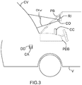
- the front cover CV is placed in a first so-called abnormal state, illustrated on figure 2 , when it is partially open while being partially retained by a notch of the locking / unlocking mechanism, and in a second state also called abnormal, illustrated in the figure figure 3 , when it is at least partially open without being retained by the locking / unlocking mechanism.
- the first abnormal state results from a partial unlocking of the front cover CV, and corresponds to a first reduction from below of the angular observation sector of the camera CO in the vertical direction.
- the field of view of the camera CO denoted cv 1 on the figure 2
- cv ref the field of vision
- the second abnormal state results from a total unlocking of the front cover CV, and corresponds to another reduction in at least a central part of the angular observation sector of the camera CO in the vertical direction.
- the CV front cover when the CV front cover is placed in its second abnormal state (see figure 3 ), the field of vision of the CO camera is reduced, or even zero, compared to its reference field of vision cv ref .
- the front cover CV is placed in a second abnormal state in which it is completely open and induces a zero field of view of the CO camera (the latter is therefore not only reduced in its central part, but also in its lower parts (bottom ) and above (top)).
- the field of view of the latter (CO) is determined in each image acquired by the camera CO (the computer CA). Then, we (the calculator CA) compare each determined field of vision with the reference field of vision cv ref , which has been previously determined in a reference image acquired when the front cover CV was in its normal state (illustrated on figure 1 ).
- the computer CA determines the current field of view of the camera CO then compares this current field of view with cv ref .
- one can determine in each acquired image the current field of view of the CO camera by determining each area allowing observation beyond the front end of the front cover CV (and therefore in front of vehicle V). It is in fact considered that the current field of view of the camera CO is what enables it to observe the environment at least in front of the front cover CV. In the example of figure 3 , this current field of vision is zero because the front cover CV prevents any observation of the environment in front of the vehicle V by the camera CO.
- the rounded shape of the lower edge (or rear) of the front cover CV, located near the windshield PB allow observation of a very small part of the environment in front of the vehicle V in an area included between this lower edge and the engine compartment, when the CV front cover is fully open.
- the front cover CV when the front cover CV is fully open it does not obstruct an upper part of the field of view of the camera CO.
- the camera CO can observe a small part of the environment in front of the vehicle V in an area above the upper (or front) edge of the front cover CV.
- the computer CA (the computer CA) considers that the front cover CV is not in its normal state in the event of determination of at least one difference in the field of vision in the first step 10 -30, and an alarm is generated in order to warn the driver of the vehicle V. It will be understood that it is the computer CA which triggers the generation of this alarm.
- the alarm can take the form of an analog or digital signal or a textual or audible message, or even a haptic one.
- a text message the latter can be displayed on at least one display screen installed permanently or temporarily in the vehicle V.
- this display screen can be that of the central instrument panel CC, or that of the table vehicle V, or a part of the windshield PB of vehicle V which is used by a head-up display device, or that of a mobile communication equipment (such as a smart phone or a electronic tablet).
- This text message can optionally be displayed simultaneously on at least two display screens.
- an audible message the latter can be broadcast by at least one loudspeaker installed permanently or temporarily in the vehicle V.
- the CO camera is already providing images for at least one other function, there is no noticeable increase in mass.
- one can compare the difference in field of view determined in the first step 10-30 with at least two predefined differences in field of view, corresponding respectively to different problems at the same time.
- CV front cover level This option is intended to determine among these different problems which one corresponds to the predefined field of view difference which is similar to the determined (current) field of view difference. In this case, an alarm is generated which is representative of the problem which has been determined. This makes it possible to establish a kind of diagnosis, rather than alerting whatever the cause (and therefore whatever the difference in field of vision determined).
- a first alarm may signal a partial unlocking of the front cover CV
- a second alarm may signal a deformation of the front cover CV (for example following an impact), which a simple contactor cannot detect. of the prior art
- a third alarm may signal at least partial opening of the front cover CV.
- the number of different problems detectable by the computer CA may be equal to two or three, or even more, and that these problems are not limited to the three examples described above.
- the alarm is also transmitted to another computer which is, for example, in charge of supervision of the motor-fan assembly and of the braking system of vehicle V. This makes it possible to slow down vehicle V with a view to stopping it to allow its driver to completely close the front cover and so that it is placed in its state normal.
- the action on the movement of the vehicle V can be variable. Indeed, in the presence of a simple partial unlocking of the front cover CV, it is possible to gradually slow down the vehicle V until it is immobilized in a secure manner. On the other hand, in the presence of at least partial opening of the front cover CV, the vehicle V must be stopped as quickly as possible, taking into account the importance of the danger.
- the alarm in the second step 40-80, can be generated in the event of a determination of a same difference in field of vision in at least two images acquired successively.
- the computer CA will trigger the generation of an alarm only if and only if it detects on at least two images acquired successively the same difference in field of vision and therefore the same problem.
- a first sub-step 10 of the first step an image is acquired with the camera CO.
- the computer CA determines in this image acquired by the camera CO the field of view of the latter (CO).
- the calculator CA compares this determined field of vision with the reference field of vision cv ref .
- a fourth sub-step 40 of the second step it (the computer CA) determines whether there actually exists a difference between the determined field of vision and cv ref .
- one terminates the detection method in a fifth sub-step 50 of the second step. We then wait for the acquisition of the next image by the CO camera.
- one (the computer CA) can, in a sixth sub-step 60 of the second step, compare the difference in field of vision determined in the fourth sub-step 40 with at least two predefined field of vision differences, corresponding respectively to different problems at the front cover CV, in order to determine the existing problem. Then, in a seventh sub-step 70 of the second step, an alarm is generated (here representative of the determined problem) in order to warn (at least) the driver of the vehicle V. Then, the process (the computer CA) ends the process. detection in an eighth sub-step 80 of the second step. We then wait for the acquisition of the following image by the CO camera.
- the invention also proposes a computer program product comprising a set of instructions which, when it is executed by processing means of the electronic circuit (or hardware) type, such as for example the computer CA, is suitable for implementing the detection method described above to detect the state in which the front cover CV of the motor vehicle V is placed.
- the detection device DD is very schematically and functionally illustrated by its computer CA.
- this computer CA can be produced by means of at least one processor, for example a digital signal (or DSP (Digital Signal Processor)), possibly associated with a random access memory to store instructions for the implementation by this processor of part of the detection method as described above.
- the detection device DD can comprise a box comprising integrated circuits (or printed), connected by wired or non-wired connections.
- integrated circuit or printed circuit is meant any type of device capable of performing at least one electrical or electronic operation.
- this DD detection device may include at least one mass memory, in particular for storing images and / or data defining the results of its analyzes (images) and calculations, an input interface for receiving data. 'at least the images (which it possibly shapes and / or demodulates and / or amplifies in a manner known per se), and an output interface for the transmission of the results of its calculations.
- the detection method can be implemented by a plurality of processors, random access memory, mass memory, input interface, output interface and / or digital signal processor.
- the detection device DD can be decentralized, within a local network (several processors linked together for example) or a wide area network.
Landscapes
- Engineering & Computer Science (AREA)
- Business, Economics & Management (AREA)
- Emergency Management (AREA)
- Physics & Mathematics (AREA)
- General Physics & Mathematics (AREA)
- Human Computer Interaction (AREA)
- Mechanical Engineering (AREA)
- Fittings On The Vehicle Exterior For Carrying Loads, And Devices For Holding Or Mounting Articles (AREA)
- Traffic Control Systems (AREA)
- Emergency Alarm Devices (AREA)
Claims (9)
- Erfassungsverfahren für ein Fahrzeug (V) eines Kraftfahrzeugtyps und mit einer vorderen Haube (CV), die einen normalen Zustand aufweist, in dem sie zum Fahren vollständig geschlossen ist, und einer Kamera (CO), die mit einem oberen Abschnitt einer Windschutzscheibe (PB) gekoppelt ist und Bilder in Richtung der Vorderseite des Fahrzeugs (V) erfasst,wobei das Verfahren einen ersten Schritt (10-30) umfasst, in dem ein Sichtfeld der Kamera (CO) in jedem erfassten Bild bestimmt wird, das Verfahren einen ersten Schritt (10-30) umfasst, in dem ein Sichtfeld der Kamera (CO) in jedem erfassten Bild bestimmt wird, und dann jedes bestimmte Sichtfeld mit einem Referenzsichtfeld verglichen wird, das in einem Referenzbild bestimmt wurde, das erfasst wurde, als sich die vordere Haube (CV) in dem normalen Zustand befand, und dadurch gekennzeichnet, dass das Verfahren einen zweiten Schritt (40-80) umfasst, in dem im Falle der Bestimmung mindestens eines Sichtfeldunterschieds davon ausgegangen wird, dass sich die vordere Haube (CV) nicht in ihrem normalen Zustand befindet, und ein Alarm erzeugt wird, um einen Fahrer des Fahrzeugs (V) zu warnen.
- Verfahren nach Anspruch 1, dadurch gekennzeichnet, dass in dem ersten Schritt (10-30) das Sichtfeld der Kamera (CO) in jedem erfassten Bild bestimmt wird, indem jeder Bereich bestimmt wird, der eine Beobachtung über ein vorderes Ende der vorderen Haube (CV) hinaus erlaubt.
- Verfahren nach Anspruch 1 oder 2, dadurch gekennzeichnet, dass in dem zweiten Schritt (40-80) die ermittelte Sichtfelddifferenz mit mindestens zwei vordefinierten Sichtfelddifferenzen verglichen wird, die jeweils unterschiedlichen Problemen an der vorderen Abdeckung (CV) entsprechen, um unter diesen Problemen dasjenige zu bestimmen, das der vordefinierten Sichtfelddifferenz entspricht, die der ermittelten Sichtfelddifferenz ähnlich ist, und dass ein für das ermittelte Problem repräsentativer Alarm erzeugt wird.
- Verfahren nach Anspruch 3, dadurch gekennzeichnet, dass in dem zweiten Schritt (40-80) die Probleme aus einer teilweisen Entriegelung der Frontabdeckung (CV) entsprechend einer ersten Abwärtsverringerung eines Sichtwinkelsektors entlang einer vertikalen Richtung ausgewählt werden, eine Verformung der vorderen Abdeckung (CV), die einer zweiten Verkleinerung von unten des Beobachtungswinkelsektors entlang der vertikalen Richtung entspricht, die größer ist als die erste Verkleinerung, und ein zumindest teilweises Öffnen der vorderen Abdeckung (CV), das zumindest einer dritten Verkleinerung in einem zentralen Abschnitt des Beobachtungswinkelsektors entlang der vertikalen Richtung entspricht, die größer ist als die zweite Verkleinerung.
- Verfahren nach einem der Ansprüche 1 bis 4, dadurch gekennzeichnet, dass in dem zweiten Schritt (40-80) ein Alarm erzeugt wird, der eine Aktion auf eine Bewegung des Fahrzeugs (V) erfordert.
- Verfahren nach einem der Ansprüche 1 bis 5, dadurch gekennzeichnet, dass in dem zweiten Schritt (40-80) der Alarm erzeugt wird, wenn in mindestens zwei nacheinander aufgenommenen Bildern der gleiche Unterschied im Sichtfeld festgestellt wird.
- Computerprogrammprodukt, das einen Satz von Befehlen umfasst, der, wenn er von einer Verarbeitungseinrichtung ausgeführt wird, geeignet ist, das Erfassungsverfahren nach einem der vorhergehenden Ansprüche zum Erfassen eines Zustands, in dem sich eine Fronthaube (CV) eines Kraftfahrzeugs (V) befindet, zu implementieren.
- Erfassungsvorrichtung (DD) für ein Fahrzeug (V) des Automobil-Typs und mit einer vorderen Haube (CV), die einen normalen Zustand aufweist, in dem sie für die Fahrt vollständig geschlossen ist, und einer Kamera (CO), die mit einem oberen Teil einer Windschutzscheibe (PB) gekoppelt ist und Bilder in Richtung der Vorderseite des Fahrzeugs (V) erfasst,wobei die Vorrichtung mindestens einen Computer (CA) umfasst, der in jedem erfassten Bild ein Sichtfeld der Kamera (CO) bestimmt, dann jedes bestimmte Sichtfeld mit dem Sichtfeld der Kamera (CO) vergleicht, und die Vorrichtung mindestens einen Computer (CA) umfasst, der in jedem erfassten Bild ein Sichtfeld der Kamera (CO) bestimmt und dann jedes bestimmte Sichtfeld mit einem Referenzsichtfeld vergleicht, das in einem Referenzbild bestimmt wurde, das erfasst wurde, als sich die Fronthaube (CV) in dem normalen Zustand befand, und dadurch gekennzeichnet, dass der Computer so konfiguriert ist, dass er im Falle der Bestimmung mindestens eines Unterschieds im Sichtfeld berücksichtigt, dass sich die Fronthaube (CV) nicht in ihrem normalen Zustand befindet, und die Erzeugung eines Alarms auslöst, um einen Fahrer des Fahrzeugs (V) zu warnen
- Kraftfahrzeug (V) mit einer vorderen Haube (CV), die einen normalen Zustand aufweist, in dem sie zum Fahren vollständig geschlossen ist, und einer Kamera (CO), die mit einem oberen Abschnitt einer Windschutzscheibe (PB) gekoppelt ist und Bilder in Richtung der Vorderseite des Fahrzeugs (V) erfasst, dadurch gekennzeichnet, dass es ferner eine Erfassungsvorrichtung (DD) nach Anspruch 8 umfasst.
Applications Claiming Priority (1)
| Application Number | Priority Date | Filing Date | Title |
|---|---|---|---|
| FR1858541A FR3086439B1 (fr) | 2018-09-20 | 2018-09-20 | Procede et dispositif de detection de l’etat d’un capot avant d’un vehicule automobile par comparaison de champs de vision |
Publications (2)
| Publication Number | Publication Date |
|---|---|
| EP3627467A1 EP3627467A1 (de) | 2020-03-25 |
| EP3627467B1 true EP3627467B1 (de) | 2021-06-02 |
Family
ID=63963252
Family Applications (1)
| Application Number | Title | Priority Date | Filing Date |
|---|---|---|---|
| EP19194892.6A Active EP3627467B1 (de) | 2018-09-20 | 2019-09-02 | Verfahren und vorrichtung zur detektion des zustands einer motorhaube eines kraftfahrzeugs durch vergleich von sichtfeldern |
Country Status (3)
| Country | Link |
|---|---|
| EP (1) | EP3627467B1 (de) |
| CN (1) | CN110920517A (de) |
| FR (1) | FR3086439B1 (de) |
Families Citing this family (3)
| Publication number | Priority date | Publication date | Assignee | Title |
|---|---|---|---|---|
| CN113706837B (zh) * | 2021-07-09 | 2022-12-06 | 上海汽车集团股份有限公司 | 一种发动机异常状态检测方法和装置 |
| FR3139512A1 (fr) * | 2022-09-14 | 2024-03-15 | Psa Automobiles Sa | Procédé et dispositif de détection fiabilisée d’ouverture d’un capot d’un véhicule |
| CN119428448A (zh) * | 2024-08-07 | 2025-02-14 | 广州汽车集团股份有限公司 | 一种前向视野盲区辅助方法、系统、装置及存储介质 |
Family Cites Families (11)
| Publication number | Priority date | Publication date | Assignee | Title |
|---|---|---|---|---|
| JPH0720697U (ja) * | 1993-09-14 | 1995-04-11 | 三菱自動車工業株式会社 | ステレオ視カメラ取付構造 |
| DE29811086U1 (de) * | 1997-08-22 | 1998-09-17 | Leopold Kostal GmbH & Co KG, 58507 Lüdenscheid | Einrichtung zum Erfassen von sich auf die Sichtqualität zum Führen eines Kraftfahrzeuges auswirkenden Einflüssen |
| DE10148639A1 (de) | 2000-10-12 | 2002-05-08 | Schlos Und Metallwarenfabrik B | Motorhaubenverschluss, insbesondere für Personenkraftfahrzeuge |
| JP3800172B2 (ja) * | 2002-12-24 | 2006-07-26 | トヨタ自動車株式会社 | 車両用周辺監視装置 |
| JP4677364B2 (ja) * | 2006-05-23 | 2011-04-27 | 株式会社村上開明堂 | 車両監視装置 |
| JP2009220688A (ja) * | 2008-03-14 | 2009-10-01 | Mazda Motor Corp | 車両用前下方視界制御装置 |
| US9128354B2 (en) * | 2012-11-29 | 2015-09-08 | Bendix Commercial Vehicle Systems Llc | Driver view adapter for forward looking camera |
| GB201410612D0 (en) * | 2014-06-13 | 2014-07-30 | Tomtom Int Bv | Methods and systems for generating route data |
| US20170161902A1 (en) * | 2015-12-02 | 2017-06-08 | Dura Operating, Llc | System for detecting vehicle fuel door status |
| JP6259482B2 (ja) * | 2016-03-18 | 2018-01-10 | 株式会社Subaru | 車両用表示制御装置 |
| US10220704B2 (en) * | 2016-10-24 | 2019-03-05 | GM Global Technology Operations LLC | Method and apparatus for door status detection |
-
2018
- 2018-09-20 FR FR1858541A patent/FR3086439B1/fr not_active Expired - Fee Related
-
2019
- 2019-09-02 EP EP19194892.6A patent/EP3627467B1/de active Active
- 2019-09-20 CN CN201910894258.3A patent/CN110920517A/zh active Pending
Also Published As
| Publication number | Publication date |
|---|---|
| FR3086439B1 (fr) | 2020-08-28 |
| FR3086439A1 (fr) | 2020-03-27 |
| CN110920517A (zh) | 2020-03-27 |
| EP3627467A1 (de) | 2020-03-25 |
Similar Documents
| Publication | Publication Date | Title |
|---|---|---|
| EP3627467B1 (de) | Verfahren und vorrichtung zur detektion des zustands einer motorhaube eines kraftfahrzeugs durch vergleich von sichtfeldern | |
| EP3590071A1 (de) | Vorrichtung zur bestimmung der aufmerksamkeit eines fahrers eines fahrzeugs, bordsystem mit solch einer vorrichtung und zugehöriges verfahren | |
| EP2988981B1 (de) | Verfahren zum automatischen leiten von fahrzeugüberwachungsinformationen an das telefon des fahrers | |
| FR3048110A1 (fr) | Procede et dispositif de detection d'un objet oublie dans l'habitacle d'un vehicule | |
| WO2017025681A1 (fr) | Système d'aide a la conduite pour un véhicule pourvu d'un système de rétrovision numérique adaptable pour manoeuvre de recul | |
| FR3099120A1 (fr) | Contrôle des positions de conduite manuelle et de conduite automatisée d’un siège de conducteur d’un véhicule | |
| FR3114432A1 (fr) | Véhicule muni d’un radar avertissant d’une possible présence d’un enfant dans son habitacle, et procédé associé | |
| FR3085335A1 (fr) | Procede d’assistance de l’utilisation d’un vehicule automobile a hayon arriere lors d’un stationnement | |
| FR3086250A1 (fr) | Procede d’assistance de l’utilisation d’un vehicule automobile a hayon arriere venant d’etre gare | |
| FR3106537A1 (fr) | Véhicule avertissant d’une possible présence d’un enfant dans son habitacle, et procédé associé | |
| FR3098276A1 (fr) | Assistance d’un véhicule suivi en cas d’éblouissement par un véhicule suiveur détecté par analyse d’images | |
| EP3080790B1 (de) | Vorrichtung zur detektion der anwesenheit einer drahtloskommunikationsausrüstung in einem fahrzeug, die von dem fahrer des fahrzeugs zurückgelassen wurde | |
| FR3104288A1 (fr) | Véhicule à écran tactile signalant un élément sélectionné sur un autre écran tactile | |
| FR3085888A1 (fr) | Pare-soleil motorise et a ecran a affichage contextuel, pour un vehicule | |
| FR3100501A1 (fr) | Procédé et dispositif de contrôle d’un véhicule en stationnement et contenant au moins un passager | |
| FR3100077A1 (fr) | Alerte d’un conducteur d’un détournement prolongé d’attention pendant une phase de conduite manuelle d’un véhicule | |
| FR3086484A1 (fr) | Procede et systeme d’assistance a la conduite d’un vehicule par affichage d’images acquises et partiellement traitees par la camera | |
| FR3084743A1 (fr) | Procede et dispositif de controle d’une direction assistee electrique d’un vehicule a colonne de direction par cable, par comparaison d’angles de volant | |
| FR3085910A1 (fr) | Procede et systeme de retrovision numerique pour un vehicule automobile | |
| EP3110661B1 (de) | Parkhilfesystemvorrichtung zur erkennung der einfahrt in eine oder der ausfahrt aus einer parkzone für einen fahrzeugführer | |
| WO2021156552A1 (fr) | Véhicule à caméra(s) d'analyse stockant des groupes d'images en présence d'évènements détectés | |
| FR3165085A1 (fr) | Système de vision intégré ou juxtaposé à un dispositif tête haute et comprenant une caméra disposant de deux champs de vision distincts | |
| FR3152762A1 (fr) | Surveillance de la fonction de feu antibrouillard arrière d’un véhicule | |
| FR3061978A1 (fr) | Dispositif d'aide a l'observation de la zone situee derriere un vehicule | |
| FR3100774A1 (fr) | Procédé et dispositif de contrôle à distance d’un véhicule en stationnement et sans passager |
Legal Events
| Date | Code | Title | Description |
|---|---|---|---|
| PUAI | Public reference made under article 153(3) epc to a published international application that has entered the european phase |
Free format text: ORIGINAL CODE: 0009012 |
|
| STAA | Information on the status of an ep patent application or granted ep patent |
Free format text: STATUS: THE APPLICATION HAS BEEN PUBLISHED |
|
| AK | Designated contracting states |
Kind code of ref document: A1 Designated state(s): AL AT BE BG CH CY CZ DE DK EE ES FI FR GB GR HR HU IE IS IT LI LT LU LV MC MK MT NL NO PL PT RO RS SE SI SK SM TR |
|
| AX | Request for extension of the european patent |
Extension state: BA ME |
|
| STAA | Information on the status of an ep patent application or granted ep patent |
Free format text: STATUS: REQUEST FOR EXAMINATION WAS MADE |
|
| 17P | Request for examination filed |
Effective date: 20200827 |
|
| RBV | Designated contracting states (corrected) |
Designated state(s): AL AT BE BG CH CY CZ DE DK EE ES FI FR GB GR HR HU IE IS IT LI LT LU LV MC MK MT NL NO PL PT RO RS SE SI SK SM TR |
|
| RAP1 | Party data changed (applicant data changed or rights of an application transferred) |
Owner name: PSA AUTOMOBILES SA |
|
| GRAP | Despatch of communication of intention to grant a patent |
Free format text: ORIGINAL CODE: EPIDOSNIGR1 |
|
| STAA | Information on the status of an ep patent application or granted ep patent |
Free format text: STATUS: GRANT OF PATENT IS INTENDED |
|
| INTG | Intention to grant announced |
Effective date: 20210205 |
|
| GRAS | Grant fee paid |
Free format text: ORIGINAL CODE: EPIDOSNIGR3 |
|
| GRAA | (expected) grant |
Free format text: ORIGINAL CODE: 0009210 |
|
| STAA | Information on the status of an ep patent application or granted ep patent |
Free format text: STATUS: THE PATENT HAS BEEN GRANTED |
|
| REG | Reference to a national code |
Ref country code: CH Ref legal event code: EP |
|
| AK | Designated contracting states |
Kind code of ref document: B1 Designated state(s): AL AT BE BG CH CY CZ DE DK EE ES FI FR GB GR HR HU IE IS IT LI LT LU LV MC MK MT NL NO PL PT RO RS SE SI SK SM TR |
|
| REG | Reference to a national code |
Ref country code: GB Ref legal event code: FG4D Free format text: NOT ENGLISH |
|
| REG | Reference to a national code |
Ref country code: AT Ref legal event code: REF Ref document number: 1399164 Country of ref document: AT Kind code of ref document: T Effective date: 20210615 |
|
| REG | Reference to a national code |
Ref country code: IE Ref legal event code: FG4D Free format text: LANGUAGE OF EP DOCUMENT: FRENCH |
|
| REG | Reference to a national code |
Ref country code: DE Ref legal event code: R096 Ref document number: 602019005034 Country of ref document: DE Ref country code: DE Ref legal event code: R084 Ref document number: 602019005034 Country of ref document: DE |
|
| REG | Reference to a national code |
Ref country code: GB Ref legal event code: 746 Effective date: 20210901 |
|
| REG | Reference to a national code |
Ref country code: LT Ref legal event code: MG9D |
|
| PG25 | Lapsed in a contracting state [announced via postgrant information from national office to epo] |
Ref country code: LT Free format text: LAPSE BECAUSE OF FAILURE TO SUBMIT A TRANSLATION OF THE DESCRIPTION OR TO PAY THE FEE WITHIN THE PRESCRIBED TIME-LIMIT Effective date: 20210602 Ref country code: HR Free format text: LAPSE BECAUSE OF FAILURE TO SUBMIT A TRANSLATION OF THE DESCRIPTION OR TO PAY THE FEE WITHIN THE PRESCRIBED TIME-LIMIT Effective date: 20210602 Ref country code: FI Free format text: LAPSE BECAUSE OF FAILURE TO SUBMIT A TRANSLATION OF THE DESCRIPTION OR TO PAY THE FEE WITHIN THE PRESCRIBED TIME-LIMIT Effective date: 20210602 Ref country code: BG Free format text: LAPSE BECAUSE OF FAILURE TO SUBMIT A TRANSLATION OF THE DESCRIPTION OR TO PAY THE FEE WITHIN THE PRESCRIBED TIME-LIMIT Effective date: 20210902 |
|
| REG | Reference to a national code |
Ref country code: NL Ref legal event code: MP Effective date: 20210602 |
|
| REG | Reference to a national code |
Ref country code: AT Ref legal event code: MK05 Ref document number: 1399164 Country of ref document: AT Kind code of ref document: T Effective date: 20210602 |
|
| PG25 | Lapsed in a contracting state [announced via postgrant information from national office to epo] |
Ref country code: SE Free format text: LAPSE BECAUSE OF FAILURE TO SUBMIT A TRANSLATION OF THE DESCRIPTION OR TO PAY THE FEE WITHIN THE PRESCRIBED TIME-LIMIT Effective date: 20210602 Ref country code: RS Free format text: LAPSE BECAUSE OF FAILURE TO SUBMIT A TRANSLATION OF THE DESCRIPTION OR TO PAY THE FEE WITHIN THE PRESCRIBED TIME-LIMIT Effective date: 20210602 Ref country code: PL Free format text: LAPSE BECAUSE OF FAILURE TO SUBMIT A TRANSLATION OF THE DESCRIPTION OR TO PAY THE FEE WITHIN THE PRESCRIBED TIME-LIMIT Effective date: 20210602 Ref country code: LV Free format text: LAPSE BECAUSE OF FAILURE TO SUBMIT A TRANSLATION OF THE DESCRIPTION OR TO PAY THE FEE WITHIN THE PRESCRIBED TIME-LIMIT Effective date: 20210602 Ref country code: NO Free format text: LAPSE BECAUSE OF FAILURE TO SUBMIT A TRANSLATION OF THE DESCRIPTION OR TO PAY THE FEE WITHIN THE PRESCRIBED TIME-LIMIT Effective date: 20210902 Ref country code: GR Free format text: LAPSE BECAUSE OF FAILURE TO SUBMIT A TRANSLATION OF THE DESCRIPTION OR TO PAY THE FEE WITHIN THE PRESCRIBED TIME-LIMIT Effective date: 20210903 |
|
| PG25 | Lapsed in a contracting state [announced via postgrant information from national office to epo] |
Ref country code: SM Free format text: LAPSE BECAUSE OF FAILURE TO SUBMIT A TRANSLATION OF THE DESCRIPTION OR TO PAY THE FEE WITHIN THE PRESCRIBED TIME-LIMIT Effective date: 20210602 Ref country code: PT Free format text: LAPSE BECAUSE OF FAILURE TO SUBMIT A TRANSLATION OF THE DESCRIPTION OR TO PAY THE FEE WITHIN THE PRESCRIBED TIME-LIMIT Effective date: 20211004 Ref country code: NL Free format text: LAPSE BECAUSE OF FAILURE TO SUBMIT A TRANSLATION OF THE DESCRIPTION OR TO PAY THE FEE WITHIN THE PRESCRIBED TIME-LIMIT Effective date: 20210602 Ref country code: RO Free format text: LAPSE BECAUSE OF FAILURE TO SUBMIT A TRANSLATION OF THE DESCRIPTION OR TO PAY THE FEE WITHIN THE PRESCRIBED TIME-LIMIT Effective date: 20210602 Ref country code: CZ Free format text: LAPSE BECAUSE OF FAILURE TO SUBMIT A TRANSLATION OF THE DESCRIPTION OR TO PAY THE FEE WITHIN THE PRESCRIBED TIME-LIMIT Effective date: 20210602 Ref country code: AT Free format text: LAPSE BECAUSE OF FAILURE TO SUBMIT A TRANSLATION OF THE DESCRIPTION OR TO PAY THE FEE WITHIN THE PRESCRIBED TIME-LIMIT Effective date: 20210602 Ref country code: SK Free format text: LAPSE BECAUSE OF FAILURE TO SUBMIT A TRANSLATION OF THE DESCRIPTION OR TO PAY THE FEE WITHIN THE PRESCRIBED TIME-LIMIT Effective date: 20210602 Ref country code: EE Free format text: LAPSE BECAUSE OF FAILURE TO SUBMIT A TRANSLATION OF THE DESCRIPTION OR TO PAY THE FEE WITHIN THE PRESCRIBED TIME-LIMIT Effective date: 20210602 Ref country code: ES Free format text: LAPSE BECAUSE OF FAILURE TO SUBMIT A TRANSLATION OF THE DESCRIPTION OR TO PAY THE FEE WITHIN THE PRESCRIBED TIME-LIMIT Effective date: 20210602 |
|
| REG | Reference to a national code |
Ref country code: DE Ref legal event code: R097 Ref document number: 602019005034 Country of ref document: DE |
|
| PLBE | No opposition filed within time limit |
Free format text: ORIGINAL CODE: 0009261 |
|
| STAA | Information on the status of an ep patent application or granted ep patent |
Free format text: STATUS: NO OPPOSITION FILED WITHIN TIME LIMIT |
|
| PG25 | Lapsed in a contracting state [announced via postgrant information from national office to epo] |
Ref country code: DK Free format text: LAPSE BECAUSE OF FAILURE TO SUBMIT A TRANSLATION OF THE DESCRIPTION OR TO PAY THE FEE WITHIN THE PRESCRIBED TIME-LIMIT Effective date: 20210602 |
|
| 26N | No opposition filed |
Effective date: 20220303 |
|
| REG | Reference to a national code |
Ref country code: BE Ref legal event code: MM Effective date: 20210930 |
|
| PG25 | Lapsed in a contracting state [announced via postgrant information from national office to epo] |
Ref country code: MC Free format text: LAPSE BECAUSE OF FAILURE TO SUBMIT A TRANSLATION OF THE DESCRIPTION OR TO PAY THE FEE WITHIN THE PRESCRIBED TIME-LIMIT Effective date: 20210602 Ref country code: AL Free format text: LAPSE BECAUSE OF FAILURE TO SUBMIT A TRANSLATION OF THE DESCRIPTION OR TO PAY THE FEE WITHIN THE PRESCRIBED TIME-LIMIT Effective date: 20210602 |
|
| PG25 | Lapsed in a contracting state [announced via postgrant information from national office to epo] |
Ref country code: LU Free format text: LAPSE BECAUSE OF NON-PAYMENT OF DUE FEES Effective date: 20210902 Ref country code: IT Free format text: LAPSE BECAUSE OF FAILURE TO SUBMIT A TRANSLATION OF THE DESCRIPTION OR TO PAY THE FEE WITHIN THE PRESCRIBED TIME-LIMIT Effective date: 20210602 Ref country code: IE Free format text: LAPSE BECAUSE OF NON-PAYMENT OF DUE FEES Effective date: 20210902 Ref country code: BE Free format text: LAPSE BECAUSE OF NON-PAYMENT OF DUE FEES Effective date: 20210930 |
|
| REG | Reference to a national code |
Ref country code: CH Ref legal event code: PL |
|
| PG25 | Lapsed in a contracting state [announced via postgrant information from national office to epo] |
Ref country code: CY Free format text: LAPSE BECAUSE OF FAILURE TO SUBMIT A TRANSLATION OF THE DESCRIPTION OR TO PAY THE FEE WITHIN THE PRESCRIBED TIME-LIMIT Effective date: 20210602 |
|
| PG25 | Lapsed in a contracting state [announced via postgrant information from national office to epo] |
Ref country code: LI Free format text: LAPSE BECAUSE OF NON-PAYMENT OF DUE FEES Effective date: 20220930 Ref country code: HU Free format text: LAPSE BECAUSE OF FAILURE TO SUBMIT A TRANSLATION OF THE DESCRIPTION OR TO PAY THE FEE WITHIN THE PRESCRIBED TIME-LIMIT; INVALID AB INITIO Effective date: 20190902 Ref country code: CH Free format text: LAPSE BECAUSE OF NON-PAYMENT OF DUE FEES Effective date: 20220930 |
|
| REG | Reference to a national code |
Ref country code: DE Ref legal event code: R081 Ref document number: 602019005034 Country of ref document: DE Owner name: STELLANTIS AUTO SAS, FR Free format text: FORMER OWNER: PSA AUTOMOBILES SA, POISSY, FR |
|
| PG25 | Lapsed in a contracting state [announced via postgrant information from national office to epo] |
Ref country code: MK Free format text: LAPSE BECAUSE OF FAILURE TO SUBMIT A TRANSLATION OF THE DESCRIPTION OR TO PAY THE FEE WITHIN THE PRESCRIBED TIME-LIMIT Effective date: 20210602 |
|
| PG25 | Lapsed in a contracting state [announced via postgrant information from national office to epo] |
Ref country code: TR Free format text: LAPSE BECAUSE OF FAILURE TO SUBMIT A TRANSLATION OF THE DESCRIPTION OR TO PAY THE FEE WITHIN THE PRESCRIBED TIME-LIMIT Effective date: 20210602 |
|
| PG25 | Lapsed in a contracting state [announced via postgrant information from national office to epo] |
Ref country code: MT Free format text: LAPSE BECAUSE OF FAILURE TO SUBMIT A TRANSLATION OF THE DESCRIPTION OR TO PAY THE FEE WITHIN THE PRESCRIBED TIME-LIMIT Effective date: 20210602 |
|
| PGFP | Annual fee paid to national office [announced via postgrant information from national office to epo] |
Ref country code: DE Payment date: 20250820 Year of fee payment: 7 |
|
| PGFP | Annual fee paid to national office [announced via postgrant information from national office to epo] |
Ref country code: GB Payment date: 20250822 Year of fee payment: 7 |
|
| PGFP | Annual fee paid to national office [announced via postgrant information from national office to epo] |
Ref country code: FR Payment date: 20250820 Year of fee payment: 7 |