EP3626927B1 - Verbundprofil für fenster und/oder türen - Google Patents
Verbundprofil für fenster und/oder türen Download PDFInfo
- Publication number
- EP3626927B1 EP3626927B1 EP18195554.3A EP18195554A EP3626927B1 EP 3626927 B1 EP3626927 B1 EP 3626927B1 EP 18195554 A EP18195554 A EP 18195554A EP 3626927 B1 EP3626927 B1 EP 3626927B1
- Authority
- EP
- European Patent Office
- Prior art keywords
- profile
- insulator
- metal
- fitting
- groove
- Prior art date
- Legal status (The legal status is an assumption and is not a legal conclusion. Google has not performed a legal analysis and makes no representation as to the accuracy of the status listed.)
- Active
Links
Images



Classifications
-
- E—FIXED CONSTRUCTIONS
- E06—DOORS, WINDOWS, SHUTTERS, OR ROLLER BLINDS IN GENERAL; LADDERS
- E06B—FIXED OR MOVABLE CLOSURES FOR OPENINGS IN BUILDINGS, VEHICLES, FENCES OR LIKE ENCLOSURES IN GENERAL, e.g. DOORS, WINDOWS, BLINDS, GATES
- E06B3/00—Window sashes, door leaves, or like elements for closing wall or like openings; Layout of fixed or moving closures, e.g. windows in wall or like openings; Features of rigidly-mounted outer frames relating to the mounting of wing frames
- E06B3/04—Wing frames not characterised by the manner of movement
- E06B3/263—Frames with special provision for insulation
- E06B3/26301—Frames with special provision for insulation with prefabricated insulating strips between two metal section members
- E06B3/26303—Frames with special provision for insulation with prefabricated insulating strips between two metal section members with thin strips, e.g. defining a hollow space between the metal section members
-
- E—FIXED CONSTRUCTIONS
- E06—DOORS, WINDOWS, SHUTTERS, OR ROLLER BLINDS IN GENERAL; LADDERS
- E06B—FIXED OR MOVABLE CLOSURES FOR OPENINGS IN BUILDINGS, VEHICLES, FENCES OR LIKE ENCLOSURES IN GENERAL, e.g. DOORS, WINDOWS, BLINDS, GATES
- E06B3/00—Window sashes, door leaves, or like elements for closing wall or like openings; Layout of fixed or moving closures, e.g. windows in wall or like openings; Features of rigidly-mounted outer frames relating to the mounting of wing frames
- E06B3/32—Arrangements of wings characterised by the manner of movement; Arrangements of movable wings in openings; Features of wings or frames relating solely to the manner of movement of the wing
- E06B3/34—Arrangements of wings characterised by the manner of movement; Arrangements of movable wings in openings; Features of wings or frames relating solely to the manner of movement of the wing with only one kind of movement
- E06B3/36—Arrangements of wings characterised by the manner of movement; Arrangements of movable wings in openings; Features of wings or frames relating solely to the manner of movement of the wing with only one kind of movement with a single vertical axis of rotation at one side of the opening, or swinging through the opening
- E06B3/362—Double winged doors or windows
-
- E—FIXED CONSTRUCTIONS
- E06—DOORS, WINDOWS, SHUTTERS, OR ROLLER BLINDS IN GENERAL; LADDERS
- E06B—FIXED OR MOVABLE CLOSURES FOR OPENINGS IN BUILDINGS, VEHICLES, FENCES OR LIKE ENCLOSURES IN GENERAL, e.g. DOORS, WINDOWS, BLINDS, GATES
- E06B3/00—Window sashes, door leaves, or like elements for closing wall or like openings; Layout of fixed or moving closures, e.g. windows in wall or like openings; Features of rigidly-mounted outer frames relating to the mounting of wing frames
- E06B3/04—Wing frames not characterised by the manner of movement
- E06B3/263—Frames with special provision for insulation
- E06B2003/26349—Details of insulating strips
- E06B2003/26387—Performing extra functions
- E06B2003/26389—Holding sealing strips or forming sealing abutments
-
- E—FIXED CONSTRUCTIONS
- E06—DOORS, WINDOWS, SHUTTERS, OR ROLLER BLINDS IN GENERAL; LADDERS
- E06B—FIXED OR MOVABLE CLOSURES FOR OPENINGS IN BUILDINGS, VEHICLES, FENCES OR LIKE ENCLOSURES IN GENERAL, e.g. DOORS, WINDOWS, BLINDS, GATES
- E06B3/00—Window sashes, door leaves, or like elements for closing wall or like openings; Layout of fixed or moving closures, e.g. windows in wall or like openings; Features of rigidly-mounted outer frames relating to the mounting of wing frames
- E06B3/04—Wing frames not characterised by the manner of movement
- E06B3/263—Frames with special provision for insulation
- E06B2003/26349—Details of insulating strips
- E06B2003/26387—Performing extra functions
- E06B2003/2639—Provisions for fittings, e.g. locks or hinges
-
- E—FIXED CONSTRUCTIONS
- E06—DOORS, WINDOWS, SHUTTERS, OR ROLLER BLINDS IN GENERAL; LADDERS
- E06B—FIXED OR MOVABLE CLOSURES FOR OPENINGS IN BUILDINGS, VEHICLES, FENCES OR LIKE ENCLOSURES IN GENERAL, e.g. DOORS, WINDOWS, BLINDS, GATES
- E06B3/00—Window sashes, door leaves, or like elements for closing wall or like openings; Layout of fixed or moving closures, e.g. windows in wall or like openings; Features of rigidly-mounted outer frames relating to the mounting of wing frames
- E06B3/04—Wing frames not characterised by the manner of movement
- E06B3/263—Frames with special provision for insulation
- E06B2003/26396—Frames with special provision for insulation specially adapted for sheet metal frames
-
- E—FIXED CONSTRUCTIONS
- E06—DOORS, WINDOWS, SHUTTERS, OR ROLLER BLINDS IN GENERAL; LADDERS
- E06B—FIXED OR MOVABLE CLOSURES FOR OPENINGS IN BUILDINGS, VEHICLES, FENCES OR LIKE ENCLOSURES IN GENERAL, e.g. DOORS, WINDOWS, BLINDS, GATES
- E06B3/00—Window sashes, door leaves, or like elements for closing wall or like openings; Layout of fixed or moving closures, e.g. windows in wall or like openings; Features of rigidly-mounted outer frames relating to the mounting of wing frames
- E06B3/54—Fixing of glass panes or like plates
- E06B3/58—Fixing of glass panes or like plates by means of borders, cleats, or the like
- E06B3/5807—Fixing of glass panes or like plates by means of borders, cleats, or the like not adjustable
- E06B3/5821—Fixing of glass panes or like plates by means of borders, cleats, or the like not adjustable hooked on or in the frame member, fixed by clips or otherwise elastically fixed
Definitions
- the invention relates to a composite profile with the features of the preamble of claim 1.
- the composite profile can be used in particular for producing windows and/or doors.
- the invention relates to a window or door element with at least one movable sash which comprises a composite profile according to the invention.
- Composite profiles for the production of windows and/or doors are known from the prior art, which comprise at least two metal profiles and an insulating profile for thermal separation of the two metal profiles.
- the metal profiles have a high degree of dimensional rigidity, so that they can bear high loads.
- a comparatively high thermal conductivity proves to be a disadvantage, so that thermal separation is necessary to prevent the formation of a thermal bridge.
- the insulating profile used for thermal separation is usually made of plastic, since plastic has a significantly lower thermal conductivity than metal.
- the insulating profile is usually connected to the two metal profiles in a force-fitting and form-fitting manner.
- a composite profile and a method for producing the composite profile are exemplified in the application EP 3 048 231 A1 by the same applicant.
- a composite profile of the type mentioned above reveals the DE 298 05 579 U1 .
- the present invention is based on the task of further developing a composite profile of the above-mentioned type in such a way that the inclusion of necessary fitting components is optimized.
- the inclusion of necessary fitting components should not be at the expense of the thermal separation, so that a composite profile is created that meets the highest requirements for thermal insulation.
- the composite profile should also have the narrowest possible visible widths.
- the proposed composite profile for windows and/or doors comprises at least one metal profile and an insulator, wherein the insulator is connected to the metal profile in a force-fitting and/or form-fitting manner, namely via an end section which is accommodated in a receiving groove of the metal profile.
- the insulator and the metal profile work together to form a fitting groove, wherein the insulator has a web section arranged at an angle to the end section for delimiting the fitting groove and at least one web section for a force-fitting and/or form-fitting connection to a glass holding profile.
- the metal profile is produced by forming a metal sheet, wherein two metal sheet edges extending in the longitudinal direction of the metal profile delimit the receiving groove.
- a fitting groove is usually used to accommodate a fitting component of a window and/or door.
- the fitting component ensures that the window or door can be opened and closed.
- a The movable sash of the window and/or door can be mounted so that it can rotate and/or tilt using a fitting component.
- a fitting groove can be used to accommodate other accessories, such as a seal (e.g. a sliding seal or an automatic floor seal), an additional lock and/or an electronic component (e.g. for locking control).
- the fitting groove that accommodates the fitting component is usually arranged in an area that has a comparatively high level of strength, in particular dimensional stability.
- this is usually the area of the metal profile.
- the metal profile forms the fitting groove.
- the formation of the fitting groove requires space, which is usually at the expense of thermal separation and results in a reduction in thermal protection.
- the insulator and the metal profile work together to form a fitting groove.
- the fitting groove is not formed by the metal profile alone, but by the metal profile and the insulator.
- the space taken up by the fitting groove is therefore not at the expense of the thermal separation, which in turn has a positive effect on thermal insulation.
- the insulator has a web section arranged at an angle to the end section.
- the angular arrangement is particularly clearly visible in the cross-section of the insulator.
- the angle that the web section and the end section of the insulator enclose can be 90°, for example.
- the web section arranged at an angle to the end section can in particular form a lateral boundary wall of the fitting groove.
- the insulator is provided with at least one web section for a force-fitting and/or form-fitting connection to a glass retaining profile.
- This means that the insulator is not only involved in the formation of the fitting groove, but also in the reception and/or fixing of the glass retaining profile.
- the reception and/or fixing of the glass retaining profile is therefore also not at the expense of the thermal separation, which in turn is an advantage in terms of With the help of the glass holding profile, not only a pane of glass but also a panel can be held.
- the metal profile of the composite profile has been produced from a metal sheet by forming, in particular by roll forming. In this way, a metal profile with a complex profile cross-section can be produced comparatively easily and inexpensively.
- the receiving groove of the metal profile which serves to connect the metal profile to the insulator in a force-fitting and/or form-fitting manner, is delimited by two metal sheet edges extending in the longitudinal direction of the metal profile.
- the metal sheet edges can be plastically deformed in a simple manner, for example by rolling, in order to create the force-fitting and/or form-fitting connection between the metal profile and the insulator.
- the metal sheet edges delimiting the receiving groove can each have a flange or a fold at their ends.
- the flange or fold reinforces the edge area and can also be used to create a form-fitting connection between the metal profile and the insulator. The arrangement is then carried out in such a way that the flange or fold engages behind an undercut area of the insulator.
- the web section delimiting the fitting groove extends in the longitudinal direction of the insulator.
- the longitudinal direction means a direction running parallel to the longitudinal direction of the profile of the insulator.
- the groove thus extends in the longitudinal direction of the profile, so that the fitting component and/or accessory accommodated therein also runs in the longitudinal direction of the profile or parallel to an edge of a frame made from the composite profile for a window and/or a door.
- frames can be formed which have locking devices or circumferential seals extending along a closing edge.
- the web section of the insulator preferably has a cross-sectional width that ensures sufficient strength, in particular dimensional stability, so that a fitting component or other accessory accommodated in the fitting groove is permanently securely supported and fixed.
- the web section of the insulator interacts with a web section of the metal profile to limit the fitting groove.
- the metal profile has a web section arranged at an angle to the receiving groove to limit the fitting groove.
- the angular arrangement is particularly clearly visible in the cross-section of the metal profile.
- the angle that the web section and the receiving groove of the metal profile enclose can be 90°, for example.
- the web section arranged at an angle to the receiving groove can in particular form a lateral boundary wall of the fitting groove.
- the web section of the metal profile preferably extends in the longitudinal direction of the metal profile, i.e. parallel to the web section of the insulator. In this way, a fitting groove is created which has a constant width in the longitudinal direction.
- the metal profile preferably has a profile section in the profile cross-section which delimits the receiving groove on the one hand and the fitting groove on the other.
- This can in particular be a profile section which forms a lateral boundary wall of the receiving groove and at the same time a groove base of the fitting groove. In this way, the space available for forming the grooves is used optimally.
- the profile section of the metal profile forming the groove base of the fitting groove can also have at least one rib-like geometry on the fitting groove side that extends in the longitudinal direction of the metal profile and that is raised relative to the groove base, thus enabling the height of a fitting component accommodated in the fitting groove to be adjusted.
- a purely linear contact of the fitting component with the rib-like geometry proves to be advantageous.
- the profile section forming the groove base of the fitting groove preferably has at least two rib-like elevations to form an intermediate groove that can be used to guide and/or position fastening means for fastening the fitting component or accessories.
- the insulator forms at least one further groove that runs parallel to, in particular adjacent to, the fitting groove.
- both grooves are arranged on the same side of the insulator.
- the further groove can be used to accommodate commercially available accessories (e.g. seals, additional locks and/or electronic components) or at least one further fitting component.
- the further groove can therefore also be a further fitting groove. This can be designed the same or similar to the first fitting groove.
- the further groove is separated from the fitting groove by the aforementioned web section of the insulator. In this case, the web section is used to delimit both grooves, i.e. the fitting groove and the further groove, so that the formation of the grooves takes up less space.
- the fitting groove and/or the additional groove have a standardized, preferably standardized dimension. This means that fitting components and/or accessories from different manufacturers can be inserted into the respective groove.
- the fitting groove and/or the additional groove can form a Euro groove 16x8 and/or a Euro groove 8x4.
- the web section intended for the force-locking and/or form-locking connection to the glass holding profile is preferably designed with an angled cross-section.
- the angled shape of the web section in particular makes it possible to achieve a form-locking connection to the glass holding profile.
- the web section can have an L-shaped cross-section.
- the web section for the force-locking and/or form-locking connection to the glass holding profile is arranged on the side of the insulator that faces away from the fitting groove. The insulator thus forms a glass side and a fitting side.
- the insulator preferably has an undercut region which enables a positive connection with the metal profile.
- the insulator has a substantially or at least approximately mirror-symmetrical profile cross-section.
- the mirror-symmetrical profile cross-section simplifies the manufacture and assembly of the insulator.
- the axis of symmetry preferably runs centrally between two end sections of the insulator, so that the insulator can have a glass side and a fitting side that are designed differently.
- the insulator is preferably made of plastic.
- Plastic has a significantly reduced thermal conductivity compared to metal, so that an effective thermal separation can be achieved via the insulator.
- the insulator is preferably made of a plastic that has a high strength, for example polyamide, in particular PA6.6. Alternatively or additionally, it is proposed that the plastic is fiber-reinforced.
- the plastic can in particular have glass fibers for reinforcement.
- the insulator is made of PA6.6 GF25.
- the high strength and/or reinforcement of the plastic ensures a permanently secure reception and fixation of fitting components and/or accessories in the grooves provided for this purpose.
- the metal profile preferably forms a profile loop in cross-section, which is formed by profile sections that are immediately adjacent to the receiving groove and/or at least partially lie on top of one another.
- Complex profile cross-sections can be realized via the profile loop.
- web and/or flange-forming profile cross-sections can be created that have a high degree of dimensional rigidity.
- the web and/or the flange can be used as a stop or the like. If the profile sections of the profile loop lie on top of one another at least partially, so that the metal sheet lies twice in this area, the dimensional rigidity can be further increased.
- the metal profile of the proposed composite profile is preferably thermally separated from another metal profile by the insulator.
- the composite profile comprises at least two metal profiles and the insulator for thermally separating the two metal profiles.
- the metal profiles determine the visible widths of the composite profile.
- the insulator is preferably connected to the other metal profile in a force-fitting and/or form-fitting manner via an end section received in a receiving groove of the other metal profile.
- the connection can in particular be designed in the same way as the connection of the insulator to the first metal profile. In this case, the insulator has identical End sections for connection to the metal profiles. This simplifies the manufacture and/or assembly of the insulator.
- a window or door element with at least one movable sash is also proposed, which comprises a composite profile according to the invention.
- a fitting component can be inserted into the fitting groove of the composite profile, which serves for the movable, in particular rotating and/or tilting, mounting of the sash.
- the sash is preferably mounted on a frame profile, which can also comprise a composite profile according to the invention or is formed by such a profile.
- the fitting groove of the composite profile of the sash can be used to accommodate accessories, such as additional locks, seals and/or electronic components.
- the window or door element in question can be either a single-leaf or a multi-leaf system.
- the composite profile of the movable leaf preferably works together with a composite profile of another movable leaf to form a stop.
- a mullion stop is formed.
- the mullion stop makes it possible to dispense with a fixed post as a stop, so that the overall visible width of the profiles is minimized.
- the composite profiles that interact to form a stop have fitting grooves facing each other that are offset from each other in the profile cross-section. This means that when the window or door is closed, the fitting grooves of the composite profiles that interact to form a stop are not opposite each other, but are next to each other or one behind the other. In this way, the stop depth can be maximized, which in turn leads to a minimization of the overall visible width of the profiles.
- Drawings 1-5 show a schematic representation of a composite profile according to the invention, wherein the web section for the force-fitting and/or form-fitting connection with a glass holding profile is not explicitly shown.
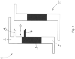
- a composite profile 1 for forming a sash 14 of a window element can be seen, which comprises a first metal profile 2, a second metal profile 2' and an intermediate insulator 3 for thermal separation of the two metal profiles 2, 2'.
- the insulator 3 and the first metal profile 2 work together to form a fitting groove 6.
- a fitting component (not shown) or another accessory, such as a seal, an additional lock or an electronic component, can be inserted into the fitting groove 6.
- the fitting groove 6 is delimited on the one hand by a web section 7 of the insulator 3 and on the other hand by a web section 8 of the metal profile 2, so that the two web sections 7, 8 each form lateral boundary walls of the fitting groove 6.
- the insulator 3 and the metal profile 2 work together to form the fitting groove 6, the insulator 3 can be made larger so that the distance between the two metal profiles 2, 2' increases. In this way, an effective thermal separation is achieved, which improves the thermal protection.
- a composite profile 15 can also be seen, which in this case serves to form a frame of the window element.
- the composite profile 15 is designed in a similar way to the composite profile 1 of the sash 14, but without the fitting groove 6. This means that the composite profile 15 can be a conventional composite profile.
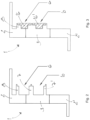
- Fig. 2 is a modification of the composite profile 1 of the Fig. 1 shown.
- the modification consists in that in addition to the fitting groove 6, a further groove 10 is provided, which is formed by the insulator 3.
- the insulator 3 has a further web section 7', which runs parallel to the web section 7.
- the web section 7 can thus be used on the one hand to limit the fitting groove 6, and on the other hand to limit the further groove 10.
- a fitting component or an accessory part can be inserted into the further groove 10, so that greater variation options exist in order to take the respective structural conditions into account.
- the additional groove 10 is designed in the same way as the fitting groove 6, namely as a Euro groove 16x8.
- Fig. 3 shows a further modification of a composite profile 1 according to the invention.
- the fitting groove 6 and the further groove 10 are each designed as a Euro groove 8x4.
- a fitting component 16, 16' is inserted in both grooves 6, 10.
- the Fig. 4 1 shows a further preferred embodiment of a composite profile 1 according to the invention.
- the fitting groove 6 is designed as a Euro groove 16x8.
- the further groove 10, on the other hand, is designed as a Euro groove 8x4.
- the Fig. 5 shows a composite profile 1 in connection with another composite profile 1', which serves to form another wing 14'.
- the composite profiles 1, 1' of both wings 14, 14' work together to form a stop. This means that the wings 14, 14' strike into each other.
- the stop is therefore a mullion stop.
- the window with the wings is therefore a mullion window.
- the fitting groove 6' of the composite profile 1' is arranged offset from the fitting groove 6 of the composite profile 1.
- the fitting groove 6' is formed solely by the insulator 3', so that it lies completely in the area of the thermal separation. The formation of the fitting groove 6' is therefore not at the expense of the thermal separation. In this way, an optimal thermal separation is achieved between the two metal profiles 2" and 2′′′ of the composite profile 1'.
- a fitting component 16, 16' is inserted into each of the two fitting grooves 6, 6'.
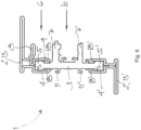
- a further preferred embodiment of a composite profile 1 according to the invention is shown in Fig. 6 It has two metal profiles 2, 2' and an insulator 3 for thermally separating the two metal profiles 2, 2'.
- Both metal profiles 2, 2' have been produced from a metal sheet by forming, in particular by roll forming.
- the metal sheet edges each delimit a receiving groove 4, 4' for receiving an end section 5, 5' of the insulator 3.
- the ends of the metal sheet edges are each provided with a fold 18, 18', which engage behind an undercut area of the end sections 5, 5'. In this way, a positive connection of the insulator 3 with the metal profiles 2, 2' is achieved.
- Profile sections adjoining the respective receiving groove 4, 4' form a profile loop 13, 13', which serves to form at least one web and at least one flange.
- the profile loop 13 also forms a web section 8, which serves to laterally delimit a fitting groove 6.
- the fitting groove 6 is delimited by a web section 7 of the insulator 3.
- the web section 7 also delimits - together with a web section 7' - another groove 10. Fitting components 16, 16' can be inserted into both the fitting groove 6 and the other groove 10 (see Fig. 7 ).
- the fitting groove 6 is limited on the groove base side by a profile section 9 of the metal profile 2, which at the same time forms a lateral limitation of the receiving groove 4. In this way, the space available for forming the grooves 4, 6 is used optimally.
- the insulator 3 On the side facing away from the grooves 6, 10, the insulator 3 has web sections 11, 11', which can be used to hold and fix glass retaining profiles 12 (see Fig. 7 ).
- the web sections 11, 11' are designed with an angled or L-shaped cross-section. Since the load on the web sections 11, 11' is significantly lower than that on the web sections 7, 7', they have significantly smaller cross-sections.
- a fitting groove 6 and a further groove 10 are formed on the left side of the Fig. 7 for example.
- a fitting component 16 is inserted into the fitting groove 6.
- a fitting component 16, 16' is inserted into each of the two grooves 6, 10.
- the frame of the window element shown in cross-section is also designed as a thermally separated composite profile, whereby the composite profile 15 does not have a fitting groove 6.
- a composite profile 1 for a double-leaf window element with two movable leaves 14, 14', which strike each other, is shown by way of example in the Fig. 8
- the composite profile 1 is almost identical to the composite profile 1 of the Fig. 6
- the metal profile 2 merely forms a slightly differently shaped profile loop 13.
- the composite profile 1 interacts with a composite profile 1' to form a stop, whereby the stop is designed as a faceplate stop (see Fig. 9 ).
- the further composite profile 1' has an insulator 3' for the thermal separation of two metal profiles 2", 2′′′. Furthermore, the insulator 3' forms a further groove, which in this case serves as a fitting groove 6' (see Fig. 9 ) and is therefore designated as such.
- the fitting groove 6' is offset from the fitting groove 6 of the composite profile 1.
- the fitting components 16, 16' inserted into the fitting grooves 6, 6' do not hit each other.
- the offset arrangement makes optimal use of the available space, so that the stop depth can be increased in favor of a narrow overall visible width.
Landscapes
- Engineering & Computer Science (AREA)
- Civil Engineering (AREA)
- Structural Engineering (AREA)
- Wing Frames And Configurations (AREA)
Description
- Die Erfindung betrifft ein Verbundprofil mit den Merkmalen des Oberbegriffs des Anspruchs 1. Das Verbundprofil kann insbesondere zur Herstellung von Fenstern und/oder Türen verwendet werden. Darüber hinaus betrifft die Erfindung ein Fenster- oder Türelement mit mindestens einem beweglichen Flügel, der ein erfindungsgemäßes Verbundprofil umfasst.
- Sofern vorliegend von einem Fenster oder einem Fensterelement die Rede ist, umfasst dieser Begriff auch solche, die als Fenstertüren ausgebildet sind.
- Aus dem Stand der Technik sind Verbundprofile zur Herstellung von Fenstern und/oder Türen bekannt, die mindestens zwei Metallprofile und ein Isolierprofil zur thermischen Trennung der beiden Metallprofile umfassen. Die Metallprofile besitzen eine hohe Formsteifigkeit, so dass sie hohe Lasten aufnehmen können. Als nachteilig erweist sich jedoch eine vergleichsweise hohe Wärmeleifähigkeit, so dass eine thermische Trennung erforderlich ist, um die Ausbildung einer Wärmebrücke zu verhindern. Das der thermischen Trennung dienende Isolierprofil ist üblicherweise aus Kunststoff gefertigt, da Kunststoff gegenüber Metall eine deutlich geringere Wärmeleitfähigkeit aufweist. Um einen ausreichend stabilen Verbund zwischen dem Isolierprofil und den beiden Metallprofilen zu erreichen, wird das Isolierprofil in der Regel kraft- und formschlüssig mit den beiden Metallprofilen verbunden.
- Ein Verbundprofil und ein Verfahren zur Herstellung des Verbundprofils gehen beispielhaft aus der Anmeldung
EP 3 048 231 A1 derselben Anmelderin hervor. - Weitere Verbundprofile sind zum Beispiel aus der
EP 1 138 864 A1 , aus derDE 100 15 838 A1 und aus derGB 2 470 217 A - Ein Verbundprofil der eingangs genannten Art offenbart die
DE 298 05 579 U1 . - Ausgehend von dem vorstehend genannten Stand der Technik liegt der vorliegenden Erfindung die Aufgabe zugrunde, ein Verbundprofil der vorstehend genannten Art derart weiterzuentwickeln, dass die Aufnahme notwendiger Beschlagbauteile optimiert wird. Insbesondere soll die Aufnahme notwendiger Beschlagbauteile nicht zu Lasten der thermischen Trennung gehen, so dass ein Verbundprofil geschaffen wird, das höchsten Anforderungen an den Wärmeschutz genügt. Das Verbundprofil soll zudem möglichst schmale Ansichtsbreiten aufweisen.
- Zur Lösung der Aufgabe wird das Verbundprofil mit den Merkmalen des Anspruchs 1 vorgeschlagen. Vorteilhafte Weiterbildungen der Erfindung sind den Unteransprüchen zu entnehmen. Ferner wird ein Fenster- oder Türelement mit einem solchen Verbundprofil vorgeschlagen.
- Das vorgeschlagene Verbundprofil für Fenster und/oder Türen umfasst mindestens ein Metallprofil und einen Isolator, wobei der Isolator kraft- und/oder formschlüssig mit dem Metallprofil verbunden ist, und zwar über einen Endabschnitt, der in einer Aufnahmenut des Metallprofils aufgenommen ist. Der Isolator und das Metallprofil wirken eine Beschlagnut ausbildend zusammen, wobei der Isolator einen winklig zum Endabschnitt angeordneten Stegabschnitt zur Begrenzung der Beschlagnut sowie mindestens einen Stegabschnitt zur kraft- und/oder formschlüssigen Verbindung mit einem Glashalteprofil aufweist. Erfindungsgemäß ist das Metallprofil durch Umformen aus einem Metallblech hergestellt worden, wobei zwei sich in Längsrichtung des Metallprofils erstreckende Metallblechkanten die Aufnahmenut begrenzen.
- Eine Beschlagnut dient in der Regel der Aufnahme eines Beschlagbauteils eines Fensters und/oder einer Tür. Das Beschlagbauteil stellt sicher, dass das Fenster bzw. die Tür geöffnet und geschlossen werden kann. Beispielsweise kann ein beweglicher Flügel des Fensters und/oder der Tür über ein Beschlagbauteil dreh- und/oder kippbeweglich gelagert werden. Darüber hinaus kann eine Beschlagnut zur Aufnahme sonstigen Zubehörs, beispielsweise einer Dichtung (z. B. einer Schleifdichtung oder einer automatischen Bodendichtung), einer Zusatzverriegelung und/oder eines elektronischen Bauteils (z. B. zur Schließkontrolle) genutzt werden.
- Um ein Beschlagbauteil dauerhaft sicher zu lagern und/oder zu fixieren, wird die das Beschlagbauteil aufnehmende Beschlagnut in der Regel in einem Bereich angeordnet, der eine vergleichsweise hohe Festigkeit, insbesondere Formsteifigkeit, besitzt. Bei einem Verbundprofil, umfassend mindestens ein Metallprofil und einen Isolator, ist dies üblicherweise der Bereich des Metallprofils. Das heißt, dass das Metallprofil die Beschlagnut ausbildet. Die Ausbildung der Beschlagnut wiederum erfordert Platz, der in der Regel zu Lasten der thermischen Trennung geht und eine Verringerung des Wärmeschutzes zur Folge hat.
- Im Unterschied dazu wirken bei dem vorgeschlagenen Verbundprofil der Isolator und das Metallprofil eine Beschlagnut ausbildend zusammen. Das heißt, dass hier die Beschlagnut nicht durch das Metallprofil allein, sondern durch das Metallprofil und den Isolator ausgebildet wird. Der von der Beschlagnut beanspruchte Platz geht somit nicht zu Lasten der thermischen Trennung, was sich wiederum positiv auf den Wärmeschutz auswirkt.
- Der Isolator weist zur Begrenzung der Beschlagnut einen winklig zum Endabschnitt angeordneten Stegabschnitt auf. Die winklige Anordnung ist insbesondere im Querschnitt des Isolators gut erkennbar. Der Winkel, den der Stegabschnitt und der Endabschnitt des Isolators umschließen, kann beispielsweise 90° betragen. Der winklig zum Endabschnitt angeordnete Stegabschnitt kann insbesondere eine seitliche Begrenzungswand der Beschlagnut ausbilden.
- Darüber hinaus ist vorgesehen, dass der Isolator mindestens einen Stegabschnitt zur kraft- und/oder formschlüssigen Verbindung mit einem Glashalteprofil aufweist. Das heißt, dass der Isolator nicht nur an der Ausbildung der Beschlagnut, sondern ferner an der Aufnahme und/oder Fixierung des Glashalteprofils beteiligt ist. Die Aufnahme und/oder Fixierung des Glashalteprofils geht somit ebenfalls nicht zu Lasten der thermischen Trennung, was sich wiederum als Vorteil im Hinblick auf den Wärmeschutz auswirkt. Mit Hilfe des Glashalteprofils kann nicht nur eine Glasscheibe, sondern auch ein Paneel gehalten werden.
- Das Metallprofil des Verbundprofils ist durch Umformen, insbesondere durch Rollformen, aus einem Metallblech hergestellt worden. Auf diese Weise kann ein Metallprofil mit komplexem Profilquerschnitt vergleichsweise einfach und kostengünstig hergestellt werden. Dabei wird die Aufnahmenut des Metallprofils, die der kraft- und/oder formschlüssigen Verbindung des Metallprofils mit dem Isolator dient, durch zwei sich in Längsrichtung des Metallprofils erstreckende Metallblechkanten begrenzt. Die Metallblechkanten können in einfacher Weise, beispielsweise durch Anrollen, plastisch verformt werden, um die kraft- und/oder formschlüssige Verbindung zwischen dem Metallprofil und dem Isolator herzustellen. Des Weiteren können die die Aufnahmenut begrenzenden Metallblechkanten an ihren Enden jeweils eine Bördelung oder einen Falz aufweisen. Die Bördelung oder der Falz verstärken den Kantenbereich und können zugleich zur Herstellung eines Formschlusses zwischen dem Metallprofil und dem Isolator eingesetzt werden. Die Anordnung erfolgt dann in der Weise, dass die Bördelung oder der Falz einen Hinterschneidungsbereich des Isolators hintergreift.
- In einer Ausführungsform wird vorgeschlagen, dass der die Beschlagnut begrenzende Stegabschnitt sich in Längsrichtung des Isolators erstreckt. Mit Längsrichtung ist vorliegend eine parallel zur Profillängsrichtung des Isolators verlaufende Richtung gemeint. Die Nut erstreckt sich somit in Profillängsrichtung, so dass das hierin aufgenommene Beschlagbauteil und oder Zubehör sich ebenfalls in Profillängsrichtung bzw. parallel zu einer Kante eines aus dem Verbundprofil hergestellten Rahmens für ein Fenster und/oder eine Tür verläuft. Auf diese Weise können zum Beispiel Rahmen ausgebildet werden, die sich entlang einer Schließkante erstreckende Verriegelungseinrichtungen oder umlaufende Dichtungen aufweisen.
- Der Stegabschnitt des Isolators weist bevorzugt eine Querschnittsbreite auf, die eine ausreichende Festigkeit, insbesondere Formsteifigkeit gewährleistet, so dass ein in der Beschlagnut aufgenommenes Beschlagbauteil oder sonstiges Zubehör dauerhaft sicher gelagert und fixiert ist.
- Vorzugsweise wirkt der Stegabschnitt des Isolators mit einem Stegabschnitt des Metallprofils die Beschlagnut begrenzend zusammen.
- Des Weiteren wird daher vorgeschlagen, dass das Metallprofil zur Begrenzung der Beschlagnut einen winklig zur Aufnahmenut angeordneten Stegabschnitt aufweist. Die winklige Anordnung ist insbesondere im Querschnitt des Metallprofils gut erkennbar. Der Winkel, den der Stegabschnitt und die Aufnahmenut des Metallprofils umschließen, kann beispielsweise 90° betragen. Der winklig zur Aufnahmenut angeordnete Stegabschnitt kann insbesondere eine seitliche Begrenzungswand der Beschlagnut ausbilden.
- Um eine seitliche Begrenzung der Beschlagnut auszubilden, erstreckt sich vorzugsweise der Stegabschnitt des Metallprofils in Längsrichtung des Metallprofils, das heißt parallel zum Stegabschnitt des Isolators. Auf diese Weise wird eine Beschlagnut geschaffen, die in Längsrichtung eine gleichbleibende Breite aufweist.
- Bevorzugt weist das Metallprofil im Profilquerschnitt einen Profilabschnitt auf, der einerseits die Aufnahmenut und andererseits die Beschlagnut begrenzt. Hierbei kann es sich insbesondere um einen Profilabschnitt handeln, der eine seitliche Begrenzungswand der Aufnahmenut und zugleich einen Nutgrund der Beschlagnut ausbildet. Auf diese Weise wird der zur Ausbildung der Nuten zur Verfügung stehende Raum optimal genutzt.
- Der den Nutgrund der Beschlagnut ausbildende Profilabschnitt des Metallprofils kann zugleich beschlagnutseitig mindestens eine sich in Längsrichtung des Metallprofils erstreckende rippenartige Geometrie aufweisen, die sich gegenüber dem Nutgrund erhebt und somit eine Einstellung der Höhenlage eines in der Beschlagnut aufgenommenen Beschlagbauteils ermöglicht. Zudem erweist sich ein lediglich linienförmiger Kontakt des Beschlagbauteils an der rippenartigen Geometrie als vorteilhaft. Vorzugsweise weist der den Nutgrund der Beschlagnut ausbildende Profilabschnitt mindestens zwei rippenartige Erhebungen zur Ausbildung einer zwischenliegenden Rille auf, die zur Führung und/oder Positionierung von Befestigungsmitteln zur Befestigung des Beschlagbauteils oder von Zubehör genutzt werden kann.
- In Weiterbildung der Erfindung wird vorgeschlagen, dass der Isolator mindestens eine weitere Nut ausbildet, die parallel, insbesondere benachbart zur Beschlagnut verläuft. Vorzugsweise sind beide Nuten auf derselben Seite des Isolators angeordnet. Die weitere Nut kann zur Aufnahme von handelsüblichem Zubehör (z. B. Dichtungen, Zusatzverriegelungen und/oder elektronischen Bauteilen) oder mindestens eines weiteren Beschlagbauteils genutzt werden. Bei der weiteren Nut kann es sich daher auch um eine weitere Beschlagnut handeln. Diese kann gleich oder ähnlich der ersten Beschlagnut ausgebildet sein. Vorzugsweise ist die weitere Nut durch den bereits erwähnten Stegabschnitt des Isolators von der Beschlagnut getrennt. In diesem Fall wird der Stegabschnitt zur Begrenzung beider Nuten, das heißt der Beschlagnut und der weiteren Nut, genutzt, so dass die Ausbildung der Nuten weniger Platz in Anspruch nimmt.
- Vorteilhafterweise weist bzw. weisen die Beschlagnut und/oder die weitere Nut eine standardisierte, vorzugsweise genormte Abmessung auf. Dadurch können Beschlagbauteile und/oder Zubehörteile unterschiedlicher Hersteller in die jeweilige Nut eingesetzt werden. Beispielsweise kann bzw. können die Beschlagnut und/oder die weitere Nut eine Euronut 16x8 und/oder eine Euronut 8x4 ausbilden.
- Der zur kraft- und/oder formschlüssigen Verbindung mit dem Glashalteprofil vorgesehene Stegabschnitt ist vorzugsweise im Querschnitt abgewinkelt ausgeführt. Durch die im Querschnitt abgewinkelte Form des Stegabschnitts kann insbesondere eine formschlüssige Verbindung mit dem Glashalteprofil erreicht werden. Beispielsweise kann der Stegabschnitt einen L-förmigen Querschnitt aufweisen. Alternativ oder ergänzend wird vorgeschlagen, dass der Stegabschnitt zur kraft- und/oder formschlüssigen Verbindung mit dem Glashalteprofil auf der Seite des Isolators angeordnet ist, die der Beschlagnut abgewandt ist. Der Isolator bildet somit eine Glasseite und eine Beschlagseite aus.
- Im Bereich mindestens eines Endabschnitts weist der Isolator bevorzugt einen Hinterschneidungsbereich auf, der eine formschlüssige Verbindung mit dem Metallprofil ermöglicht.
- Bevorzugt weist der Isolator einen im Wesentlichen oder zumindest annähernd spiegelsymmetrischen Profilquerschnitt auf. Der spiegelsymmetrische Profilquerschnitt vereinfacht die Herstellung und die Montage des Isolators. Die Symmetrieachse verläuft vorzugsweise mittig zwischen zwei Endabschnitten des Isolators, so dass der Isolator eine Glasseite und eine Beschlagseite aufweisen kann, die unterschiedlich ausgebildet sind.
- Des Weiteren bevorzugt ist der Isolator aus Kunststoff gefertigt. Kunststoff besitzt gegenüber Metall eine deutlich reduzierte Wärmeleitfähigkeit, so dass über den Isolator eine effektive thermische Trennung bewirkbar ist. Vorzugsweise ist der Isolator aus einem Kunststoff gefertigt, der eine hohe Festigkeit besitzt, beispielsweise aus Polyamid, insbesondere aus PA6.6. Alternativ oder ergänzend wird vorgeschlagen, dass der Kunststoff faserverstärkt ist. Der Kunststoff kann insbesondere Glasfasern zur Verstärkung aufweisen. Gemäß einer bevorzugten Ausführungsform der Erfindung ist der Isolator aus PA6.6 GF25 gefertigt. Die hohe Festigkeit und/oder Verstärkung des Kunststoffs gewährleistet bzw. gewährleisten eine dauerhaft sichere Aufnahme und Fixierung von Beschlagbauteilen und/oder Zubehör in den hierfür vorgesehenen Nuten.
- Bevorzugt bildet das Metallprofil im Querschnitt eine Profilschleife aus, die durch Profilabschnitte gebildet wird, die an die Aufnahmenut unmittelbar angrenzen und/oder zumindest bereichsweise aufeinander liegen. Über die Profilschleife können komplexe Profilquerschnitte realisiert werden. Beispielsweise können steg- und/oder flanschausbildende Profilquerschnitte geschaffen werden, die eine hohe Formsteifigkeit besitzen. Zugleich kann der Steg und/oder der Flansch als Anschlag oder dergleichen genutzt werden. Liegen die Profilabschnitte der Profilschleife zumindest bereichsweise aufeinander, so dass das Metallblech in diesem Bereich doppelt liegt, kann die Formsteifigkeit weiter erhöht werden.
- Das Metallprofil des vorgeschlagenen Verbundprofils ist vorzugsweise durch den Isolator von einem weiteren Metallprofil thermisch getrennt. Das heißt, dass das Verbundprofil zumindest zwei Metallprofile und den Isolator zur thermischen Trennung der beiden Metallprofile umfasst. Die Metallprofile bestimmen dabei die Ansichtsbreiten des Verbundprofils. Weiterhin vorzugsweise ist der Isolator über einen in einer Aufnahmenut des weiteren Metallprofils aufgenommenen Endabschnitt kraft- und/oder formschlüssig mit dem weiteren Metallprofil verbunden. Die Verbindung kann insbesondere gleich der Verbindung des Isolators mit dem ersten Metallprofil ausgeführt sein. In diesem Fall weist der Isolator identische Endabschnitte zur Verbindung mit den Metallprofilen auf. Dadurch vereinfacht sich die Herstellung und/oder Montage des Isolators.
- Da das erfindungsgemäße Verbundprofil insbesondere zur Herstellung von Fenstern und/oder Türen geeignet ist, wird darüber hinaus ein Fenster- oder Türelement mit mindestens einem beweglichen Flügel vorgeschlagen, der ein erfindungsgemäßes Verbundprofil umfasst. In die Beschlagnut des Verbundprofils kann ein Beschlagbauteil eingesetzt werden, das der beweglichen, insbesondere dreh- und/oder kippbeweglichen Lagerung des Flügels dient. Die Lagerung des Flügels erfolgt vorzugsweise an einem Blendrahmenprofil, das ebenfalls ein erfindungsgemäßes Verbundprofil umfassen kann oder durch ein solches ausgebildet wird. Alternativ oder ergänzend kann die Beschlagnut des Verbundprofils des Flügels zur Aufnahme von Zubehör, wie beispielsweise Zusatzverriegelungen, Dichtungen und/oder elektronischen Bauteilen genutzt werden.
- Bei dem beanspruchten Fenster- oder Türelement kann es sich sowohl um eine einflügelige als auch um eine mehrflügelige Anlage handeln. Im letztgenannten Fall wirkt vorzugsweise das Verbundprofil des beweglichen Flügels mit einem Verbundprofil eines weiteren beweglichen Flügels anschlagbildend zusammen. Das heißt, dass ein Stulpanschlag ausgebildet wird. Der Stulpanschlag ermöglicht den Verzicht auf einen feststehenden Pfosten als Anschlag, so dass die Gesamtansichtsbreite der Profile minimiert wird.
- In Weiterbildung der Erfindung wird vorgeschlagen, dass die anschlagbildend zusammenwirkenden Verbundprofile einander zugewandte Beschlagnuten aufweisen, die im Profilquerschnitt versetzt zueinander angeordnet sind. Das heißt, dass bei geschlossenem Fenster bzw. geschlossener Tür die Beschlagnuten der anschlagbildend zusammenwirkenden Verbundprofile sich nicht gegenüber liegen, sondern nebeneinander bzw. hintereinander zu liegen kommen. Auf diese Weise kann die Anschlagtiefe maximiert werden, was wiederum zu einer Minimierung der Gesamtansichtsbreite der Profile führt.
- Bevorzugte Ausführungsformen der Erfindung werden nachfolgend anhand der beigefügten Zeichnungen näher beschrieben. Diese zeigen:
- Fig. 1
- einen schematischen Querschnitt durch eine erste bevorzugte Ausführungsform eines erfindungsgemäßen Verbundprofils für einen Flügel in Verbindung mit einem Verbundprofil für einen Blendrahmen,
- Fig. 2
- einen schematischen Querschnitt durch eine zweite bevorzugte Ausführungsform eines erfindungsgemäßen Verbundprofils für einen Flügel,
- Fig. 3
- einen schematischen Querschnitt durch eine dritte bevorzugte Ausführungsform eines erfindungsgemäßen Verbundprofils für einen Flügel,
- Fig. 4
- einen schematischen Querschnitt durch eine vierte bevorzugte Ausführungsform eines erfindungsgemäßen Verbundprofils für einen Flügel,
- Fig. 5
- einen schematischen Querschnitt durch eine fünfte bevorzugte Ausführungsform eines erfindungsgemäßen Verbundprofils für einen Flügel in Verbindung mit einem Verbundprofil eines weiteren Flügels,
- Fig. 6
- einen Querschnitt durch eine sechste bevorzugte Ausführungsform eines erfindungsgemäßen Verbundprofils für einen Flügel,
- Fig. 7
- einen Querschnitt durch ein einflügeliges Fensterelement, umfassend das Verbundprofil der
Fig. 6 , - Fig. 8
- einen Querschnitt durch eine siebte bevorzugte Ausführungsform eines erfindungsgemäßen Verbundprofils für einen Flügel in Verbindung mit einem Verbundprofil eines weiteren Flügels, und
- Fig. 9
- einen Querschnitt durch ein zweiflügeliges Fensterelement, um- fassend die Verbundprofile der
Fig. 8 . - Die Zeichnungen 1-5 zeigen eine schematische Darstellung eines erfindungsgemäßen Verbundprofils, wobei der Stegabschnitt zur kraft-und/oder formschlüssigen Verbindung mit einem Glashalteprofil nicht explizit dargestellt ist.
- Der
Fig. 1 ist ein Verbundprofil 1 zur Ausbildung eines Flügels 14 eines Fensterelements zu entnehmen, das ein erstes Metallprofil 2, ein zweites Metallprofil 2' sowie einen zwischenliegenden Isolator 3 zur thermischen Trennung der beiden Metallprofile 2, 2' umfasst. Der Isolator 3 und das erste Metallprofil 2 wirken dabei eine Beschlagnut 6 ausbildend zusammen. In die Beschlagnut 6 ist ein Beschlagbauteil (nicht dargestellt) oder ein sonstiges Zubehörteil, wie beispielsweise eine Dichtung, eine Zusatzverriegelung oder ein elektronisches Bauteil, einsetzbar. Die Beschlagnut 6 wird einerseits von einem Stegabschnitt 7 des Isolators 3, andererseits von einem Stegabschnitt 8 des Metallprofils 2 begrenzt, so dass die beiden Stegabschnitte 7, 8 jeweils seitliche Begrenzungswände der Beschlagnut 6 ausbilden. - Dadurch, dass der Isolator 3 und das Metallprofil 2 die Beschlagnut 6 ausbildend zusammenwirken, kann der Isolator 3 größer dimensioniert werden, so dass der Abstand zwischen den beiden Metallprofilen 2, 2' zunimmt. Auf diese Weise wird eine effektive thermische Trennung bewirkt, die den Wärmeschutz verbessert.
- Der
Fig. 1 ist ferner ein Verbundprofil 15 zu entnehmen, das vorliegend der Ausbildung eines Blendrahmens des Fensterelements dient. Das Verbundprofil 15 ist analog dem Verbundprofil 1 des Flügels 14 ausgebildet, jedoch ohne Beschlagnut 6. Das heißt, dass es sich bei dem Verbundprofil 15 um ein herkömmliches Verbundprofil handeln kann. - In der
Fig. 2 ist eine Abwandlung des Verbundprofils 1 derFig. 1 dargestellt. Die Abwandlung besteht darin, dass zusätzlich zur Beschlagnut 6 eine weitere Nut 10 vorgesehen ist, die durch den Isolator 3 ausgebildet wird. Der Isolator 3 weist hierzu einen weiteren Stegabschnitt 7' auf, der parallel zum Stegabschnitt 7 verläuft. Der Stegabschnitt 7 kann somit einerseits zur Begrenzung der Beschlagnut 6, andererseits zur Begrenzung der weiteren Nut 10 genutzt werden. Alternativ oder ergänzend zur Beschlagnut 6 kann in die weitere Nut 10 ein Beschlagbauteil oder ein Zubehörteil eingesetzt werden, so dass größere Variationsmöglichkeiten bestehen, um den jeweiligen baulichen Gegebenheiten Rechnung zu tragen. Im Beispiel derFig. 2 ist die weitere Nut 10 gleich der Beschlagnut 6 ausgeführt, und zwar als Euronut 16x8. -
Fig. 3 zeigt eine weitere Abwandlung eines erfindungsgemäßen Verbundprofils 1. Hier sind die Beschlagnut 6 und die weitere Nut 10 jeweils als Euronut 8x4 ausgeführt. Beispielhaft ist in beiden Nuten 6, 10 ein Beschlagbauteil 16, 16' eingesetzt. - Der
Fig. 4 ist eine weitere bevorzugte Ausführungsform eines erfindungsgemäßen Verbundprofils 1 zu entnehmen. Hier ist die Beschlagnut 6 als Euronut 16x8 ausgeführt. Die weitere Nut 10 ist dagegen als Euronut 8x4 ausgeführt. - Die
Fig. 5 zeigt ein Verbundprofil 1 in Verbindung mit einem weiteren Verbundprofil 1', das der Ausbildung eines weiteren Flügels 14' dient. Die Verbundprofile 1, 1' beider Flügel 14, 14' wirken anschlagbildend zusammen. Das heißt, dass die Flügel 14, 14' ineinander schlagen. Bei dem Anschlag handelt es sich demnach um einen Stulpanschlag. Das die Flügel aufweisende Fenster ist demzufolge ein Stulpfenster. Um eine möglichst geringe Gesamtansichtsbreite zu realisieren, ist die Beschlagnut 6' des Verbundprofils 1' versetzt zur Beschlagnut 6 des Verbundprofils 1 angeordnet. Die Beschlagnut 6' wird allein durch den Isolator 3' ausgebildet, so dass sie vollständig im Bereich der thermischen Trennung zu liegen kommt. Die Ausbildung der Beschlagnut 6' geht somit nicht zu Lasten der thermischen Trennung. Auf diese Weise wird eine optimale thermische Trennung zwischen den beiden Metallprofilen 2" und 2‴ des Verbundprofils 1' erreicht. In derFig. 5 ist beispielhaft in beide Beschlagnuten 6, 6' jeweils ein Beschlagbauteil 16, 16' eingesetzt. - Eine weitere bevorzugte Ausführungsform eines erfindungsgemäßen Verbundprofils 1 ist in der
Fig. 6 dargestellt. Es weist zwei Metallprofile 2, 2' sowie einen Isolator 3 zur thermischen Trennung der beiden Metallprofile 2, 2' auf. Beide Metallprofile 2, 2' sind durch Umformen, insbesondere durch Rollformen, aus einem Metallblech hergestellt worden. Die Metallblechkanten begrenzen jeweils eine Aufnahmenut 4, 4' zur Aufnahme eines Endabschnitts 5, 5' des Isolators 3. Die Enden der Metallblechkanten sind jeweils mit einem Falz 18, 18' versehen, die einen Hinterschneidungsbereich der Endabschnitte 5, 5' hintergreifen. Auf diese Weise wird eine formschlüssige Verbindung des Isolators 3 mit den Metallprofilen 2, 2' erreicht. An die jeweilige Aufnahmenut 4, 4' anschließende Profilabschnitte bilden eine Profilschleife 13, 13' aus, die der Ausformung mindestens eines Stegs und mindestens eines Flansches dient. Bei dem Metallprofil 2 bildet die Profilschleife 13 zudem einen Stegabschnitt 8 aus, welcher der seitlichen Begrenzung einer Beschlagnut 6 dient. Auf der anderen Seite wird die Beschlagnut 6 durch einen Stegabschnitt 7 des Isolators 3 begrenzt. Der Stegabschnitt 7 begrenzt zudem - gemeinsam mit einem Stegabschnitt 7' - eine weitere Nut 10. Sowohl in die Beschlagnut 6, als auch in die weitere Nut 10 können Beschlagbauteile 16, 16' eingesetzt werden (sieheFig. 7 ). - Die Beschlagnut 6 wird nutgrundseitig von einem Profilabschnitt 9 des Metallprofils 2 begrenzt, der zugleich eine seitliche Begrenzung der Aufnahmenut 4 ausbildet. Auf diese Weise wird der zur Ausbildung der Nuten 4, 6 zur Verfügung stehende Raum optimal genutzt.
- Auf der den Nuten 6, 10 abgewandten Seite weist der Isolator 3 Stegabschnitte 11, 11' auf, die zur Aufnahme und Fixierung von Glashalteprofilen 12 genutzt werden können (siehe
Fig. 7 ). Die Stegabschnitte 11, 11' sind hierzu im Querschnitt abgewinkelt bzw. L-förmig ausgeführt. Da die Belastung der Stegabschnitte 11, 11' deutlich geringer als die der Stegabschnitte 7, 7' ist, weisen sie deutlich kleinere Querschnitte auf. - In der
Fig. 7 ist das Verbundprofil 1 mit hierin eingesetzter Isoliergasscheibe 17 und Glashalteprofilen 12 dargestellt. Auf der der Isolierglasscheibe 17 abgewandten Seite des Verbundprofils 1 sind eine Beschlagnut 6 sowie eine weitere Nut 10 ausgebildet. Auf der linken Seite derFig. 7 ist beispielhaft in die Beschlagnut 6 ein Beschlagbauteil 16 eingesetzt. Auf der rechten Seite derFig. 7 ist beispielhaft in beide Nuten 6, 10 jeweils ein Beschlagbauteil 16, 16' eingesetzt. - Wie ferner der
Fig. 7 zu entnehmen ist, ist auch der Blendrahmen des im Querschnitt dargestellten Fensterelements als thermisch getrenntes Verbundprofil ausgeführt, wobei das Verbundprofil 15 keine Beschlagnut 6 aufweist. - Ein Verbundprofil 1 für ein zweiflügeliges Fensterelement mit zwei beweglichen Flügeln 14, 14', die ineinander schlagen, ist beispielhaft in der
Fig. 8 dargestellt. Das Verbundprofil 1 ist fast identisch zum Verbundprofil 1 derFig. 6 ausgebildet. Das Metallprofil 2 bildet lediglich eine etwas anders geformte Profilschleife 13 aus. Das Verbundprofil 1 wirkt mit einem Verbundprofil 1' anschlagbildend zusammen, wobei der Anschlag als Stulpanschlag ausgeführt ist (sieheFig. 9 ). Das weitere Verbundprofil 1' weist einen Isolator 3' zur thermischen Trennung zweier Metallprofile 2", 2‴ auf. Ferner bildet der Isolator 3' eine weitere Nut aus, die vorliegend als Beschlagnut 6' dient (sieheFig. 9 ) und daher als solche bezeichnet ist. - Wie insbesondere der
Fig. 9 zu entnehmen ist, ist die Beschlagnut 6' versetzt zur Beschlagnut 6 des Verbundprofils 1 angeordnet. Beim Schließen der Flügel 14, 14' schlagen somit die in die Beschlagnuten 6, 6' eingesetzten Beschlagbauteile 16, 16' nicht aneinander. Die versetzte Anordnung schöpft den zur Verfügung stehenden Raum optimal aus, so dass die Anschlagtiefe zugunsten einer schmalen Gesamtansichtsbreite erhöht werden kann. -
- 1
- Verbundprofil
- 2
- Metallprofil
- 3
- Isolator
- 4
- Aufnahmenut
- 5
- Endabschnitt
- 6
- Beschlagnut
- 7
- Stegabschnitt
- 8
- Stegabschnitt
- 9
- Profilabschnitt
- 10
- Nut
- 11
- Stegabschnitt
- 12
- Glashalteprofil
- 13
- Profilschleife
- 14
- Flügel
- 15
- Verbundprofil
- 16
- Beschlagbauteil
- 17
- Isolierglasscheibe
- 18
- Falz
Claims (15)
- Verbundprofil (1) für Fenster und/oder Türen, umfassend mindestens ein Metallprofil (2) und einen Isolator (3), der über einen in einer Aufnahmenut (4) des Metallprofils (2) aufgenommenen Endabschnitt (5) kraft- und/oder formschlüssig mit dem Metallprofil (2) verbunden ist, wobei der Isolator (3) und das Metallprofil (2) eine Beschlagnut (6) ausbildend zusammenwirken, und wobei der Isolator (3) einen winklig zum Endabschnitt (5) angeordneten Stegabschnitt (7) zur Begrenzung der Beschlagnut (6) sowie mindestens einen Stegabschnitt (11) zur kraft- und/oder formschlüssigen Verbindung mit einem Glashalteprofil (12) aufweist, dadurch gekennzeichnet, dass das Metallprofil (2) durch Umformen aus einem Metallblech hergestellt worden ist, wobei zwei sich in Längsrichtung des Metallprofils (2) erstreckende Metallblechkanten die Aufnahmenut (4) begrenzen.
- Verbundprofil (1) nach Anspruch 1, dadurch gekennzeichnet, dass der Stegabschnitt (7) zur Begrenzung der Beschlagnut (6) sich in Längsrichtung des Isolators (3) erstreckt.
- Verbundprofil (1) nach Anspruch 1 oder 2, dadurch gekennzeichnet, dass das Metallprofil (2) zur Begrenzung der Beschlagnut (6) einen winklig zur Aufnahmenut (4) angeordneten Stegabschnitt (8) aufweist, der sich vorzugsweise in Längsrichtung des Metallprofils (2) erstreckt.
- Verbundprofil (1) nach einem der vorhergehenden Ansprüche, dadurch gekennzeichnet, dass das Metallprofil (2) im Profilquerschnitt einen Profilabschnitt (9) aufweist, der einerseits die Aufnahmenut (4) und andererseits die Beschlagnut (6) begrenzt.
- Verbundprofil (1) nach einem der vorhergehenden Ansprüche, dadurch gekennzeichnet, dass der Isolator (3) mindestens eine weitere Nut (10) ausbildet, die parallel zur Beschlagnut (6) verläuft, wobei vorzugsweise die weitere Nut (10) durch den Stegabschnitt (7) von der Beschlagnut (6) getrennt ist.
- Verbundprofil (1) nach einem der vorhergehenden Ansprüche, dadurch gekennzeichnet, dass die Beschlagnut (6) und/oder die weitere Nut (10) eine standardisierte, vorzugsweise eine genormte Abmessung aufweist bzw. aufweisen.
- Verbundprofil (1) nach einem der vorhergehenden Ansprüche, dadurch gekennzeichnet, dass der Stegabschnitt (11) zur kraft- und/oder formschlüssigen Verbindung mit dem Glashalteprofil (12) im Querschnitt abgewinkelt ist und/oder auf der der Beschlagnut (6) abgewandten Seite des Isolators (3) angeordnet ist.
- Verbundprofil (1) nach einem der vorhergehenden Ansprüche, dadurch gekennzeichnet, dass der Isolator (3) einen im Wesentlichen oder zumindest annähernd spiegelsymmetrischen Profilquerschnitt aufweist.
- Verbundprofil (1) nach einem der vorhergehenden Ansprüche, dadurch gekennzeichnet, dass der Isolator (3) aus Kunststoff, beispielsweise aus Polyamid, insbesondere aus PA6.6, gefertigt ist, wobei vorzugsweise der Kunststoff faserverstärkt ist, insbesondere Glasfasern zur Verstärkung aufweist.
- Verbundprofil (1) nach einem der vorhergehenden Ansprüche, dadurch gekennzeichnet, dass das Metallprofil (2) durch Rollformen aus dem Metallblech hergestellt worden ist.
- Verbundprofil (1) nach einem der vorhergehenden Ansprüche, dadurch gekennzeichnet, dass das Metallprofil (2) im Querschnitt eine Profilschleife (13) ausbildet, die durch Profilabschnitte gebildet wird, die unmittelbar an die Aufnahmenut (4) angrenzen und/oder zumindest bereichsweise aufeinanderliegen.
- Verbundprofil (1) nach einem der vorhergehenden Ansprüche,
dadurch gekennzeichnet, dass das Metallprofil (2) durch den Isolator (3) von einem weiteren Metallprofil (2') thermisch getrennt ist, wobei vorzugsweise der Isolator (3) über einen in einer Aufnahmenut (4') des weiteren Metallprofils (2') aufgenommenen Endabschnitt (5') kraft- und/oder formschlüssig mit dem weiteren Metallprofil (2') verbunden ist. - Fenster- oder Türelement mit mindestens einem beweglichen Flügel (14), der ein Verbundprofil (1) nach einem der vorhergehenden Ansprüche umfasst.
- Fenster- oder Türelement nach Anspruch 13, dadurch gekennzeichnet, dass das Verbundprofil (1) des beweglichen Flügels (14) mit einem Verbundprofil (1') eines weiteren beweglichen Flügels (14') anschlagbildend zusammenwirkt, so dass ein Stulpanschlag ausgebildet wird.
- Fenster- oder Türelement nach Anspruch 14, dadurch gekennzeichnet, dass die anschlagbildend zusammenwirkenden Verbundprofile (1, 1') einander zugewandte Beschlagnuten (6, 6') aufweisen, die im Profilquerschnitt versetzt zueinander angeordnet sind.
Priority Applications (3)
| Application Number | Priority Date | Filing Date | Title |
|---|---|---|---|
| ES18195554T ES3016082T3 (en) | 2018-09-19 | 2018-09-19 | Composite profile for windows and/or doors |
| PL18195554.3T PL3626927T3 (pl) | 2018-09-19 | 2018-09-19 | Profil zespolony do okien i/albo drzwi |
| EP18195554.3A EP3626927B1 (de) | 2018-09-19 | 2018-09-19 | Verbundprofil für fenster und/oder türen |
Applications Claiming Priority (1)
| Application Number | Priority Date | Filing Date | Title |
|---|---|---|---|
| EP18195554.3A EP3626927B1 (de) | 2018-09-19 | 2018-09-19 | Verbundprofil für fenster und/oder türen |
Publications (3)
| Publication Number | Publication Date |
|---|---|
| EP3626927A1 EP3626927A1 (de) | 2020-03-25 |
| EP3626927B1 true EP3626927B1 (de) | 2025-02-26 |
| EP3626927C0 EP3626927C0 (de) | 2025-02-26 |
Family
ID=63642902
Family Applications (1)
| Application Number | Title | Priority Date | Filing Date |
|---|---|---|---|
| EP18195554.3A Active EP3626927B1 (de) | 2018-09-19 | 2018-09-19 | Verbundprofil für fenster und/oder türen |
Country Status (3)
| Country | Link |
|---|---|
| EP (1) | EP3626927B1 (de) |
| ES (1) | ES3016082T3 (de) |
| PL (1) | PL3626927T3 (de) |
Families Citing this family (1)
| Publication number | Priority date | Publication date | Assignee | Title |
|---|---|---|---|---|
| IT202200001406A1 (it) * | 2022-01-27 | 2023-07-27 | Serramenti Brombal S R L | Profilo metallico per serramenti e metodo per la realizzazione di tale profilo |
Citations (2)
| Publication number | Priority date | Publication date | Assignee | Title |
|---|---|---|---|---|
| EP1138864B1 (de) * | 2000-03-31 | 2004-09-01 | SCHÜCO International KG | Verbundprofil für Fenster, Fassaden, Türen oder Lichtdächer |
| DE202013105887U1 (de) * | 2013-12-20 | 2015-03-23 | SCHÜCO International KG | Blendrahmen eines Fenster- oder Türrahmens |
Family Cites Families (4)
| Publication number | Priority date | Publication date | Assignee | Title |
|---|---|---|---|---|
| DE29805579U1 (de) * | 1998-03-27 | 1998-07-16 | Kawneer Deutschland Gmbh | Wärmegedämmtes Verbundprofil |
| DE10015838A1 (de) * | 2000-03-30 | 2001-10-11 | Evg Bauprofil System Entwicklungs & Vermarktungsgesellschaft Mbh | Zusatzelement für Isolierglasscheiben |
| GB2470217A (en) * | 2009-05-14 | 2010-11-17 | Beaufort Secure Design Ltd | Insulated frame member |
| EP3048231B1 (de) | 2015-01-22 | 2023-08-30 | RP Technik GmbH Profilsysteme | Metallprofil, Verbundprofil mit einem solchen Metallprofil sowie Verfahren zur Herstellung des Metallprofils |
-
2018
- 2018-09-19 ES ES18195554T patent/ES3016082T3/es active Active
- 2018-09-19 PL PL18195554.3T patent/PL3626927T3/pl unknown
- 2018-09-19 EP EP18195554.3A patent/EP3626927B1/de active Active
Patent Citations (2)
| Publication number | Priority date | Publication date | Assignee | Title |
|---|---|---|---|---|
| EP1138864B1 (de) * | 2000-03-31 | 2004-09-01 | SCHÜCO International KG | Verbundprofil für Fenster, Fassaden, Türen oder Lichtdächer |
| DE202013105887U1 (de) * | 2013-12-20 | 2015-03-23 | SCHÜCO International KG | Blendrahmen eines Fenster- oder Türrahmens |
Also Published As
| Publication number | Publication date |
|---|---|
| ES3016082T3 (en) | 2025-05-08 |
| EP3626927A1 (de) | 2020-03-25 |
| EP3626927C0 (de) | 2025-02-26 |
| PL3626927T3 (pl) | 2025-06-23 |
Similar Documents
| Publication | Publication Date | Title |
|---|---|---|
| EP2942466B1 (de) | Verbundprofil mit Lastabtragungseinrichtungen für Befestigungsmittel eines Funktionselementes, insbesondere ein Bandelement und Verfahren zur Montage eines solchen Funktionselementes | |
| EP4473182B1 (de) | Profilanordnung eines fensters oder einer tür mit einem flügelprofil, insbesondere einem schiebeflügelprofil | |
| EP3447223B1 (de) | Bandteil eines scharnierbandes | |
| DE202022104654U1 (de) | Profilanordnung eines Fensters oder einer Tür mit einem Flügelprofil, insbesondere einem Schiebeflügelprofil | |
| EP3184723A1 (de) | Verbundprofil für fenster, türen oder dergleichen | |
| EP4446553B1 (de) | Mehrflügelige tür einer faltschiebetür | |
| EP3626927A1 (de) | Verbundprofil für fenster und/oder türen | |
| EP2708693B1 (de) | Schiebeflügelrahmen | |
| EP1437478B1 (de) | Wärmegedämmtes Verbundprofil | |
| EP2594724A1 (de) | Einbruchhemmende Tür oder einbruchhemmendes Fenster | |
| EP0845566A2 (de) | Flügeleinheit | |
| EP2072744B1 (de) | Zargenprofil für eine Hebe-Schiebetür | |
| DE20100618U1 (de) | Rahmenprofil | |
| EP2339095B1 (de) | Tür, insbesondere Kunstofftür, mit einer Schlosskastensicherung | |
| DE102011008765A1 (de) | Profilanordnung, Rahmen und Rahmenanordnung | |
| WO2000071845A1 (de) | Riegelstangenbeschlag für ein fenster oder eine tür | |
| EP2122092B1 (de) | Beschlag | |
| EP4202170B1 (de) | Verbinder, stossverbindung und verfahren zu deren herstellung | |
| EP2270297B1 (de) | Sprengwirkungshemmender und/oder einbruchhemmender Gebäudeabschluss | |
| EP4424968B1 (de) | Verbundprofil, rahmen und verfahren zur herstellung des verbundprofils | |
| EP3656955B1 (de) | Schliessteil | |
| DE4339752C2 (de) | Beschlaganordnung für Flügel von Fenstern oder Türen | |
| EP4325017A1 (de) | Isoliersteg zum verbinden zweier profilelemente zur herstellung eines wärmegedämmten profils und ein solches profil | |
| DE29800306U1 (de) | Beschlag für einen Flügelrahmen von Fenstern oder Türen | |
| EP4446550A1 (de) | Eckfenster oder ecktür mit abstellbaren und parallel zum festen rahmen verschiebbaren schiebeflügeln |
Legal Events
| Date | Code | Title | Description |
|---|---|---|---|
| PUAI | Public reference made under article 153(3) epc to a published international application that has entered the european phase |
Free format text: ORIGINAL CODE: 0009012 |
|
| STAA | Information on the status of an ep patent application or granted ep patent |
Free format text: STATUS: THE APPLICATION HAS BEEN PUBLISHED |
|
| AK | Designated contracting states |
Kind code of ref document: A1 Designated state(s): AL AT BE BG CH CY CZ DE DK EE ES FI FR GB GR HR HU IE IS IT LI LT LU LV MC MK MT NL NO PL PT RO RS SE SI SK SM TR |
|
| AX | Request for extension of the european patent |
Extension state: BA ME |
|
| STAA | Information on the status of an ep patent application or granted ep patent |
Free format text: STATUS: REQUEST FOR EXAMINATION WAS MADE |
|
| 17P | Request for examination filed |
Effective date: 20200414 |
|
| RBV | Designated contracting states (corrected) |
Designated state(s): AL AT BE BG CH CY CZ DE DK EE ES FI FR GB GR HR HU IE IS IT LI LT LU LV MC MK MT NL NO PL PT RO RS SE SI SK SM TR |
|
| RAV | Requested validation state of the european patent: fee paid |
Extension state: MA Effective date: 20200925 Extension state: MD Effective date: 20200925 |
|
| RAX | Requested extension states of the european patent have changed |
Extension state: BA Payment date: 20200925 Extension state: ME Payment date: 20200925 |
|
| STAA | Information on the status of an ep patent application or granted ep patent |
Free format text: STATUS: EXAMINATION IS IN PROGRESS |
|
| 17Q | First examination report despatched |
Effective date: 20230330 |
|
| RAP1 | Party data changed (applicant data changed or rights of an application transferred) |
Owner name: JANSEN AG |
|
| GRAP | Despatch of communication of intention to grant a patent |
Free format text: ORIGINAL CODE: EPIDOSNIGR1 |
|
| STAA | Information on the status of an ep patent application or granted ep patent |
Free format text: STATUS: GRANT OF PATENT IS INTENDED |
|
| INTG | Intention to grant announced |
Effective date: 20241010 |
|
| GRAS | Grant fee paid |
Free format text: ORIGINAL CODE: EPIDOSNIGR3 |
|
| GRAA | (expected) grant |
Free format text: ORIGINAL CODE: 0009210 |
|
| STAA | Information on the status of an ep patent application or granted ep patent |
Free format text: STATUS: THE PATENT HAS BEEN GRANTED |
|
| AK | Designated contracting states |
Kind code of ref document: B1 Designated state(s): AL AT BE BG CH CY CZ DE DK EE ES FI FR GB GR HR HU IE IS IT LI LT LU LV MC MK MT NL NO PL PT RO RS SE SI SK SM TR |
|
| REG | Reference to a national code |
Ref country code: GB Ref legal event code: FG4D Free format text: NOT ENGLISH |
|
| REG | Reference to a national code |
Ref country code: CH Ref legal event code: EP |
|
| REG | Reference to a national code |
Ref country code: DE Ref legal event code: R096 Ref document number: 502018015589 Country of ref document: DE |
|
| REG | Reference to a national code |
Ref country code: IE Ref legal event code: FG4D Free format text: LANGUAGE OF EP DOCUMENT: GERMAN |
|
| U01 | Request for unitary effect filed |
Effective date: 20250313 |
|
| U07 | Unitary effect registered |
Designated state(s): AT BE BG DE DK EE FI FR IT LT LU LV MT NL PT RO SE SI Effective date: 20250318 |
|
| REG | Reference to a national code |
Ref country code: ES Ref legal event code: FG2A Ref document number: 3016082 Country of ref document: ES Kind code of ref document: T3 Effective date: 20250508 |
|
| PG25 | Lapsed in a contracting state [announced via postgrant information from national office to epo] |
Ref country code: RS Free format text: LAPSE BECAUSE OF FAILURE TO SUBMIT A TRANSLATION OF THE DESCRIPTION OR TO PAY THE FEE WITHIN THE PRESCRIBED TIME-LIMIT Effective date: 20250526 |
|
| PG25 | Lapsed in a contracting state [announced via postgrant information from national office to epo] |
Ref country code: IS Free format text: LAPSE BECAUSE OF FAILURE TO SUBMIT A TRANSLATION OF THE DESCRIPTION OR TO PAY THE FEE WITHIN THE PRESCRIBED TIME-LIMIT Effective date: 20250626 Ref country code: NO Free format text: LAPSE BECAUSE OF FAILURE TO SUBMIT A TRANSLATION OF THE DESCRIPTION OR TO PAY THE FEE WITHIN THE PRESCRIBED TIME-LIMIT Effective date: 20250526 |
|
| PG25 | Lapsed in a contracting state [announced via postgrant information from national office to epo] |
Ref country code: HR Free format text: LAPSE BECAUSE OF FAILURE TO SUBMIT A TRANSLATION OF THE DESCRIPTION OR TO PAY THE FEE WITHIN THE PRESCRIBED TIME-LIMIT Effective date: 20250226 |
|
| PG25 | Lapsed in a contracting state [announced via postgrant information from national office to epo] |
Ref country code: GR Free format text: LAPSE BECAUSE OF FAILURE TO SUBMIT A TRANSLATION OF THE DESCRIPTION OR TO PAY THE FEE WITHIN THE PRESCRIBED TIME-LIMIT Effective date: 20250527 |
|
| REG | Reference to a national code |
Ref country code: CH Ref legal event code: U11 Free format text: ST27 STATUS EVENT CODE: U-0-0-U10-U11 (AS PROVIDED BY THE NATIONAL OFFICE) Effective date: 20251001 |
|
| PG25 | Lapsed in a contracting state [announced via postgrant information from national office to epo] |
Ref country code: SM Free format text: LAPSE BECAUSE OF FAILURE TO SUBMIT A TRANSLATION OF THE DESCRIPTION OR TO PAY THE FEE WITHIN THE PRESCRIBED TIME-LIMIT Effective date: 20250226 |
|
| PGFP | Annual fee paid to national office [announced via postgrant information from national office to epo] |
Ref country code: PL Payment date: 20250915 Year of fee payment: 8 |
|
| VS25 | Lapsed in a validation state [announced via postgrant information from nat. office to epo] |
Ref country code: MD Free format text: LAPSE BECAUSE OF FAILURE TO SUBMIT A TRANSLATION OF THE DESCRIPTION OR TO PAY THE FEE WITHIN THE PRESCRIBED TIME-LIMIT Effective date: 20250226 |
|
| PGFP | Annual fee paid to national office [announced via postgrant information from national office to epo] |
Ref country code: GB Payment date: 20250919 Year of fee payment: 8 |
|
| PG25 | Lapsed in a contracting state [announced via postgrant information from national office to epo] |
Ref country code: CZ Free format text: LAPSE BECAUSE OF FAILURE TO SUBMIT A TRANSLATION OF THE DESCRIPTION OR TO PAY THE FEE WITHIN THE PRESCRIBED TIME-LIMIT Effective date: 20250226 |
|
| PG25 | Lapsed in a contracting state [announced via postgrant information from national office to epo] |
Ref country code: SK Free format text: LAPSE BECAUSE OF FAILURE TO SUBMIT A TRANSLATION OF THE DESCRIPTION OR TO PAY THE FEE WITHIN THE PRESCRIBED TIME-LIMIT Effective date: 20250226 |
|
| U20 | Renewal fee for the european patent with unitary effect paid |
Year of fee payment: 8 Effective date: 20250930 |
|
| PLBE | No opposition filed within time limit |
Free format text: ORIGINAL CODE: 0009261 |
|
| STAA | Information on the status of an ep patent application or granted ep patent |
Free format text: STATUS: NO OPPOSITION FILED WITHIN TIME LIMIT |
|
| REG | Reference to a national code |
Ref country code: CH Ref legal event code: L10 Free format text: ST27 STATUS EVENT CODE: U-0-0-L10-L00 (AS PROVIDED BY THE NATIONAL OFFICE) Effective date: 20260107 |
|
| PGFP | Annual fee paid to national office [announced via postgrant information from national office to epo] |
Ref country code: CH Payment date: 20251001 Year of fee payment: 8 |
|
| PGFP | Annual fee paid to national office [announced via postgrant information from national office to epo] |
Ref country code: ES Payment date: 20251030 Year of fee payment: 8 |
|
| 26N | No opposition filed |
Effective date: 20251127 |
|
| VS25 | Lapsed in a validation state [announced via postgrant information from nat. office to epo] |
Ref country code: MA Free format text: LAPSE BECAUSE OF FAILURE TO SUBMIT A TRANSLATION OF THE DESCRIPTION OR TO PAY THE FEE WITHIN THE PRESCRIBED TIME-LIMIT; INVALID AB INITIO Effective date: 20180919 |
|
| REG | Reference to a national code |
Ref country code: CH Ref legal event code: R17 Free format text: ST27 STATUS EVENT CODE: U-0-0-R10-R17 (AS PROVIDED BY THE NATIONAL OFFICE) Effective date: 20260529 |
|
| VS25 | Lapsed in a validation state [announced via postgrant information from nat. office to epo] |
Ref country code: MA Free format text: LAPSE BECAUSE OF FAILURE TO SUBMIT A TRANSLATION OF THE DESCRIPTION OR TO PAY THE FEE WITHIN THE PRESCRIBED TIME-LIMIT Effective date: 20250226 |
|
| PG25 | Lapsed in a contracting state [announced via postgrant information from national office to epo] |
Ref country code: MC Free format text: LAPSE BECAUSE OF FAILURE TO SUBMIT A TRANSLATION OF THE DESCRIPTION OR TO PAY THE FEE WITHIN THE PRESCRIBED TIME-LIMIT Effective date: 20250226 |
|
| U1O | Appointed representative for the unitary patent procedure deleted after the registration of the unitary effect | ||
| U1N | Appointed representative for the unitary patent procedure changed after the registration of the unitary effect |
Representative=s name: E. BLUM & CO. AG; CH |
|
| PG25 | Lapsed in a contracting state [announced via postgrant information from national office to epo] |
Ref country code: IE Free format text: LAPSE BECAUSE OF NON-PAYMENT OF DUE FEES Effective date: 20250919 |