EP3626599B1 - Neigungstrimmeinstellungssystem für einen aussenbordmotor - Google Patents
Neigungstrimmeinstellungssystem für einen aussenbordmotor Download PDFInfo
- Publication number
- EP3626599B1 EP3626599B1 EP19197215.7A EP19197215A EP3626599B1 EP 3626599 B1 EP3626599 B1 EP 3626599B1 EP 19197215 A EP19197215 A EP 19197215A EP 3626599 B1 EP3626599 B1 EP 3626599B1
- Authority
- EP
- European Patent Office
- Prior art keywords
- tilt
- trim
- outboard motor
- motion
- controller
- Prior art date
- Legal status (The legal status is an assumption and is not a legal conclusion. Google has not performed a legal analysis and makes no representation as to the accuracy of the status listed.)
- Active
Links
Images


Classifications
-
- B—PERFORMING OPERATIONS; TRANSPORTING
- B63—SHIPS OR OTHER WATERBORNE VESSELS; RELATED EQUIPMENT
- B63H—MARINE PROPULSION OR STEERING
- B63H20/00—Outboard propulsion units, e.g. outboard motors or Z-drives; Arrangements thereof on vessels
- B63H20/08—Means enabling movement of the position of the propulsion element, e.g. for trim, tilt or steering; Control of trim or tilt
- B63H20/10—Means enabling trim or tilt, or lifting of the propulsion element when an obstruction is hit; Control of trim or tilt
Definitions
- the present invention relates to a tilt-trim system for an outboard motor.
- Document JP 2012 166 573 A discloses a control apparatus of an outboard motor, which carries out trim adjustment of the outboard motor using motive power means.
- the control apparatus has a learning mode for setting the optimal angle of trim by learning performed with a constant throttle opening and gradually changing the trim angle.
- a tilt-trim device that causes an outboard motor attached to a watercraft to perform a tilt-trim motion
- the tilt-trim device includes, for instance, a motor and a tilt shaft extending in the right-and-left direction.
- the outboard motor is rotated about the tilt shaft. Accordingly, the outboard motor performs the tilt-trim motion such that the lower part thereof elevates or lowers.
- the outboard motor or an operator seat is provided with an operating switch for operating the tilt-trim device.
- the operating switch is, for instance, a push-button switch.
- An operator is capable of operating the tilt-trim motion of the outboard motor by pushing the operating switch.
- said object is solved by a tilt-trim system having the features of independent claim 1.
- said object is also solved by a method of controlling a tilt-trim device having the features of independent claim 7.
- Preferred embodiments are laid down in the dependent claims.
- a tilt-trim system for an outboard motor includes a tilt-trim device, an operating switch and a controller.
- the tilt-trim device causes the outboard motor to perform a tilt-trim motion.
- the operating switch is a switch for operating the tilt-trim device.
- the controller is connected to the tilt-trim device and the operating switch.
- the controller is programmed to execute the following processing.
- the controller determines whether or not an operation of the operating switch has been performed a plurality of times within a predetermined period of time when receiving a signal indicating the operation from the operating switch.
- the controller controls the tilt-trim device under an automatic control mode when the operation has been performed the plurality of times within the predetermined period of time.
- the controller controls the tilt-trim device such that the tilt-trim device automatically causes the outboard motor to continuously perform the tilt-trim motion within a motion range set in advance.
- the controller deactivates the tilt-trim device when the outboard motor reaches either a predetermined upper limit or a predetermined lower limit of the motion range.
- the controller changes the motion range in accordance with a setting signal for setting the motion range when receiving the setting signal.
- a method relates to a method of controlling a tilt-trim device causing an outboard motor to perform a tilt-trim motion.
- the method includes the following processing.
- First processing refers to receiving a signal indicating an operation of an operating switch for operating the tilt-trim device.
- Second processing refers to determining whether or not the operation has been performed a plurality of times within a predetermined period of time.
- Third processing refers to controlling the tilt-trim device under an automatic control mode such that the tilt-trim device automatically causes the outboard motor to continuously perform the tilt-trim motion within a motion range set in advance when the operation has been performed the plurality of times within the predetermined period of time.
- Fourth processing refers to deactivating the tilt-trim device when the outboard motor reaches either a predetermined upper limit or a predetermined lower limit of the motion range.
- Fifth processing refers to changing the motion range in accordance with a setting signal for setting the motion range when the setting signal is received.
- the tilt-trim motion of the outboard motor can be automatically continued under the automatic control mode without a continuous operation of the operating switch by an operator. Additionally, the tilt-trim motion of the outboard motor is automatically stopped when the outboard motor reaches either the predetermined upper limit or the predetermined lower limit of the motion range set in advance, and the motion range can be arbitrarily changed by the setting signal. Accordingly, convenience in operation for causing the outboard motor to perform the tilt-trim motion can be enhanced.
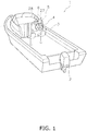
- FIG. 1 is a perspective view of a watercraft 1 in which a control system for an outboard motor 2 according to the preferred embodiment is installed.
- the outboard motor 2 is attached to the stern of the watercraft 1.
- the outboard motor 2 generates a thrust for propelling the watercraft 1.
- the single outboard motor 2 is mounted to the watercraft 1, but alternatively, two or more outboard motors 2 may be mounted to the watercraft 1.
- the watercraft 1 includes an operator seat 3.
- the operator seat 3 is provided with a steering member 4, a first remote control 5 and a second remote control 6.
- the steering member 4 is a member for allowing an operator to operate the turning direction of the watercraft 1.
- the steering member 4 is, for instance, a steering wheel.
- the first remote control 5 is a device for allowing the operator to regulate the velocity of the watercraft 1.
- the first remote control 5 is also a device for allowing the operator to switch between forward movement and backward movement of the watercraft 1.
- the second remote control 6 will be described below.
- FIG. 2 is a side view of the outboard motor 2.
- the outboard motor 2 includes an outboard motor body 10 and a bracket 11.
- the outboard motor body 10 is attached to the watercraft 1 through the bracket 11.
- the outboard motor body 10 includes an engine 12, a driveshaft 13, a propeller shaft 14 and a shift mechanism 15.
- the engine 12 generates the thrust for propelling the watercraft 1.
- the engine 12 includes a crankshaft 16.
- the crankshaft 16 extends in the vertical direction.
- the driveshaft 13 is connected to the crankshaft 16.
- the driveshaft 13 extends in the vertical direction.
- the propeller shaft 14 extends in the back-and-forth direction.
- the propeller shaft 14 is connected to the driveshaft 13 through the shift mechanism 15.
- a propeller 17 is connected to the propeller shaft 14.
- the shift mechanism 15 switches the rotational direction of power to be transmitted from the driveshaft 13 to the propeller shaft 14.
- the shift mechanism 15 includes a plurality of gears and a clutch that changes meshing of gears.
- the bracket 11 includes a tilt-trim shaft 18 and a steering shaft 19.
- the tilt-trim shaft 18 extends in the right-and-left direction.
- the bracket 11 supports the outboard motor body 10 such that the outboard motor body 10 is rotatable about the tilt-trim shaft 18.
- the steering shaft 19 extends in the vertical direction.
- the bracket 11 supports the outboard motor body 10 such that the outboard motor body 10 is rotatable about the steering shaft 19.
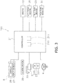
- FIG. 3 is a schematic diagram showing a control system 100 for the outboard motor 2.
- the control system 100 for the outboard motor 2 includes a controller 21.
- the controller 21 includes a processor such as a CPU and a memory 211 including a RAM, a ROM and so forth.
- the controller 21 stores a program and data for controlling the outboard motor 2.
- the controller 21 is communicably connected to the steering member 4, the first remote control 5 and the second remote control 6, all of which are described above, through wired or wireless communication.
- the steering member 4 is rotatable right and left from a middle position.
- the steering member 4 outputs an operating signal, which indicates the position thereof to the controller 21.
- the first remote control 5 includes a throttle member 22.
- the throttle member 22 is, for instance, a throttle lever.
- the throttle member 22 is operable from a zero operation position to a forwardly moving directional side and a backwardly moving directional side.
- the first remote control 5 outputs an operating signal, which indicates the position of the throttle member 22, to the controller 21.
- the controller 21 receives the operating signal, i.e., a signal indicating the operating amount of the throttle member 22, from the first remote control 5.
- the controller 21 outputs a command signal to the engine 12 such that the engine rotational speed is increased or reduced in accordance with the operating amount of the throttle member 22. Therefore, the operator can regulate the velocity of the watercraft 1 by operating the throttle member 22.
- the control system 100 for the outboard motor 2 includes a steering device 26.
- the steering device 26 rotates the outboard motor body 10 about the steering shaft 19 so as to turn the outboard motor body 10 in the right-and-left direction.
- the steering device 26 includes, for instance, a hydraulic pump and a hydraulic cylinder.
- the steering device 26 may include another type of actuator such as an electric motor.
- the controller 21 receives the operating signal, i.e., a signal indicating the operating amount and the operating direction of the steering member 4, from the steering member 4.
- the controller 21 outputs a command signal to the steering device 26 such that the outboard motor body 10 is turned in the right-and-left direction in accordance with the operating amount and the operating direction of the steering member 4. Therefore, the operator is capable of regulating the moving direction of the watercraft 1 by operating the steering member 4.
- the second remote control 6 includes an input device 27 and a display 28.
- the input device 27 outputs a signal indicating an operation performed by the operator.
- the input device 27 is a touchscreen, for instance, and detects an operation of at least one software key displayed on the display 28.
- the input device 27 may include at least one hard key and may detect an operation of the at least one hard key.
- the display 28 is, for instance, an LCD (Liquid Crystal Display) or an OLED (Organic Light Emitting Diode) display.
- the display 28 may be of another type.
- the display 28 displays a screen in accordance with a command signal transmitted thereto from the controller 21.
- the control system 100 for the outboard motor 2 includes an alarm device 29.
- the alarm device 29 outputs predetermined alert information in accordance with a command signal transmitted thereto from the controller 21.
- the alarm device 29 includes, for instance, a speaker, and the alert information takes the form of an alarm sound (a buzzer sound, etc.) to be outputted from the speaker.
- the alarm device 29 may be, for instance, an warning light (a rotary light, etc.), and the alert information may take the form of light to be emitted from the warning light.
- the control system 100 for the outboard motor 2 includes a tilt-trim device 25.
- the tilt-trim device 25 rotates the outboard motor body 10 about the tilt-trim shaft 18 so as to tilt the outboard motor body 10 in the up-and-down direction.
- the tilt-trim device 25 includes, for instance, an electric motor.
- the tilt-trim device 25 may include another type of actuator such as a hydraulic motor.
- the control system 100 for the outboard motor 2 includes a position sensor 31.
- the position sensor 31 detects a position of the outboard motor 2 performing a tilt-trim motion (hereinafter referred to as "a tilt-trim position").
- the tilt-trim position is, for instance, the tilt-trim angle of the outboard motor 2 and indicates the height ofthe outboard motor 2 to be changed by the tilt-trim motion.
- the position sensor 31 outputs a signal, indicating the tilt-trim position, to the controller 21.
- the control system 100 for the outboard motor 2 includes a PTT switch 23.
- the PTT switch 23 is an operating switch for causing the outboard motor 2 to perform the tilt-trim motion.
- the PTT switch 23 is disposed on, for instance, the outboard motor body 10. Alternatively, the PTT switch 23 may be disposed on another device such as the first remote control 5.
- the PTT switch 23 includes an UP button 230 and a DN button 231.
- the UP button 230 is operated for elevating the outboard motor 2.
- the DN button 231 is operated for lowering the outboard motor 2.
- the PTT switch 23 is a momentary switch. Specifically, while being pressed, each of the UP button 230 and the DN button 231 is kept in an operational state and outputs a signal indicating an operation thereof. While being not pressed, each of the UP button 230 and the DN button 231 is kept in a nonoperational state.
- the signal which indicates the operation of the PTT switch 23 is outputted to the controller 21.
- the controller 21 controls the tilt-trim device 25 in response to the operation of the PTT switch 23.
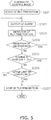
- FIG. 4 is a flowchart showing the processing for controlling the tilt-trim device 25.
- step S101 the controller 21 determines whether or not it has received the signal indicating the operation of the PTT switch 23.
- the controller 21 has not received the signal indicating the operation of the PTT switch 23, the tilt-trim device 25 is kept in a deactivated state.
- the processing proceeds to step S102.
- step S102 the controller 21 determines whether or not the operation of the PTT switch 23 has been performed a plurality of times within a predetermined period of time.
- the controller 21 herein determines that the operation of the PTT switch 23 has been performed the plurality of times within the predetermined period of time when the controller 21 has intermittently received the signal indicating the operation of the PTT switch 23 the plurality of times within the predetermined period of time.
- the controller 21 determines whether or not the UP button 230 has been operated a predetermined plurality of times or more within the predetermined period of time.
- the controller 21 determines whether or not the DN button 231 has been operated the predetermined plurality of times or more within the predetermined period of time. For example, the controller 21 determines whether or not the aforementioned operation has been performed twice or more in one second.
- step S103 When the operation of the PTT switch 23 has not been performed the plurality of times within the predetermined period of time, the processing proceeds to step S103. For example, when the operation of the PTT switch 23 has been continuously performed only once for the predetermined period of time or more, the processing proceeds to step S103.
- step S103 the controller 21 controls the tilt-trim device 25 under a manual control mode.
- the controller 21 activates the tilt-trim device 25 only while the operation ofthe PTT switch 23 is being continued.
- the controller 21 controls the tilt-trim device 25 so as to continuously elevate the outboard motor 2.
- the controller 21 deactivates the tilt-trim device 25.
- the controller 21 controls the tilt-trim device 25 so as to continuously lower the outboard motor 2.
- the controller 21 deactivates the tilt-trim device 25.
- the tilt-trim motion of the outboard motor 2 is performed within a range of a full trim-in position and a full tilt-out position.
- the full trim-in position indicates the lowest position of the outboard motor 2 performing the tilt-trim motion.
- the full tilt-out position indicates the highest position of the outboard motor 2 performing the tilt-trim motion.
- step S104 the controller 21 determines whether or not the engine 12 is being driven.
- the controller 21 determines whether or not the engine 12 is being driven based on, for instance, a signal transmitted thereto from a sensor for detecting the rotational speed of the engine 12. It should be noted that the controller 21 determines that the engine 12 is being driven even when the engine 12 is idling.
- step S104 determines that the engine 12 is being driven in step S104
- the controller 21 controls the tilt-trim device 25 under the manual control mode in step S103.
- step S105 determines that the engine 12 is not being driven in step S104
- step S105 the controller 21 controls the tilt-trim device 25 under an automatic control mode.
- the controller 21 automatically continues the tilt-trim motion of the outboard motor 2 within a motion range set in advance. For example, when the operation of the UP button 230 has been performed the plurality of times within the predetermined period of time, the controller 21 automatically continues the tilt-trim motion, by which the outboard motor 2 is elevated, within the motion range set in advance even after stop of the operation of the UP button 230.
- the controller 21 automatically continues the tilt-trim motion, by which the outboard motor 2 is lowered, within the motion range set in advance even after stop of the operation of the DN button 231.
- FIG. 5 is a flowchart showing processing executed by the controller 21 under the automatic control mode.
- the controller 21 controls the tilt-trim device 25 so as to start the tilt-trim motion.
- the controller 21 causes the tilt-trim device 25 to start the tilt-trim motion by which the outboard motor 2 is elevated.
- the controller 21 causes the tilt-trim device 25 to start the tilt-trim motion by which the outboard motor 2 is lowered.
- step S202 the controller 21 outputs alarm.
- the controller 21 herein outputs the command signal to the alarm device 29 so as to cause the alarm device 29 to output an alarm sound.
- the controller 21 causes the alarm device 20 to output the alarm sound during the tilt-trim motion under the automatic control mode.
- step S203 the controller 21 detects the tilt-trim position.
- the controller 21 herein detects the tilt-trim position based on the signal transmitted thereto from the position sensor 31.
- step S204 the controller 21 determines whether or not it has received the signal, indicating the operation of the PTT switch 23, from the PTT switch 23.
- the controller 21 determines that it has received the signal indicating the operation of the PTT switch 23 from the PTT switch 23.
- the controller 21 causes the tilt-trim device 25 to stop the tilt-trim motion in step S207.
- the controller 21 deactivates the tilt-trim device 25 when detecting that the PTT switch 23 has been operated once during the tilt-trim motion of the outboard motor 2 under the automatic control mode.
- the controller 21 determines that it has not received the signal indicating the operation of the PTT switch 23 from the PTT switch 23, the tilt-trim motion is continued and the processing proceeds to step S205.
- step S205 the controller 21 determines whether or not a value of change in the tilt-trim position of the outboard motor 2 within the predetermined period of time is less than or equal to a predetermined threshold Th1.
- the controller 21 obtains the value of change in the tilt-trim position of the outboard motor 2 based on the signal transmitted thereto from the position sensor 31.
- Values of the predetermined period of time and the threshold Th1 are set to be appropriate for detecting a foreign object getting stuck in at least either the tilt-trim device 25 or the bracket 11.
- the controller 21 causes the tilt-trim device 25 to stop the tilt-trim motion in step S207.
- the value of change in the tilt-trim position of the outboard motor 2 within the predetermined period of time is greater than the predetermined threshold Th1, the tilt-trim motion is continued and the processing proceeds to step S206.
- step S206 the controller 21 determines whether or not the tilt-trim position has reached either a predetermined upper limit position or a predetermined lower limit position. Both the upper limit position and the lower limit position have been preliminarily set and stored in the controller 21. Both the upper limit position and the lower limit position are set to fall in the range of the full trim-in position and the full tilt-out position.
- the controller 21 causes the tilt-trim device 25 to stop the tilt-trim motion in step S207. Accordingly, the controller 21 ends the automatic control mode.
- FIG. 6A is a flowchart showing processing for setting the upper limit position.
- FIG. 6B is a flowchart showing processing for setting the lower limit position.
- step S301 the controller 21 causes the display 28 to display a setting screen 40 for setting the motion range.
- FIG. 7 is a diagram showing an example of the setting screen 40.
- the setting screen 40 includes an upper limit setting button 41 and a lower limit setting button 42.
- step S302 the controller 21 determines whether or not an upper limit setting operation has been performed.
- the controller 21 determines that the upper limit setting operation has been performed when having received a signal, indicating an operation of the aforementioned upper limit setting button 41, from the input device 27.
- the processing proceeds to step S303.
- step S303 the controller 21 obtains the tilt-trim position based on the signal transmitted thereto from the position sensor 31.
- the controller 21 obtains the tilt-trim position of the outboard motor 2 at the point of time that the upper limit setting operation has been performed.
- step S304 the controller 21 sets the obtained tilt-trim position of the outboard motor 2 as the upper limit position, and stores the tilt-trim position set as the upper limit position in the memory 211.
- a user moves the outboard motor 2 to a desired position by operating the PTT switch 23 to cause the outboard motor 2 to perform the tilt-trim motion. It should be noted that at this time, the outboard motor 2 is moved within the range of the full trim-in position and the full tilt-out position.
- the controller 21 sets the tilt-trim position of the outboard motor 2 at this point of time as the upper limit position and stores the tilt-trim position set as the upper limit position in the memory 211.
- step S301 similarly causes the display 28 to display the setting screen 40 in step S401.
- step S402 the controller 21 determines whether or not a lower limit setting operation has been performed.
- the controller 21 determines that the lower limit setting operation has been performed when having received a signal indicating an operation of the aforementioned lower limit setting button 42 from the input device 27.
- the processing proceeds to step S403.
- step S403 the controller 21 obtains the tilt-trim position based on the signal transmitted thereto from the position sensor 31.
- the controller 21 obtains the tilt-trim position of the outboard motor 2 at the point of time that the lower limit setting operation has been performed.
- step S404 the controller 21 sets the obtained tilt-trim position of the outboard motor 2 as the lower limit position, and stores the tilt-trim position set as the lower limit position in the memory 211.
- the user moves the outboard motor 2 to a desired position by operating the PTT switch 23 to cause the outboard motor 2 to perform the tilt-trim motion. It should be noted that at this time, the outboard motor 2 is moved within the range of the full trim-in position and the full tilt-out position.
- the controller 21 sets the tilt-trim position of the outboard motor 2 at this point of time as the lower limit position and stores the tilt-trim position set as the lower limit position in the memory 211. It should be noted that default values are looked up and used as the upper and lower limits of the tilt-trim position before setting the upper and lower limits.
- the tilt-trim motion can be automatically continued under the automatic control mode without continuously operating the PTT switch 23.
- Either the automatic control mode or the manual control mode is selected depending on the frequency of operating the UP button 230 within the predetermined period of time. Also, either the automatic control mode or the manual control mode is selected depending on the frequency of operating the DN button 231 within the predetermined period of time. Because of this, the control mode for controlling the tilt-trim device 25 can be switched between the automatic control mode and the manual control mode by either the UP button 230 or the DN button 231.
- the motion range under the automatic control mode is settable between the full trim-in position and the full tilt-out position by the input device 27. Because of this, the motion range under the automatic control mode is settable by either a user or a dealer.
- the controller 21 causes the tilt-trim device 25 to stop the tilt-trim motion. Accordingly, when the PTT switch 23 is operated by the user, the automatic control mode can be stopped along the way.
- the controller 21 causes the tilt-trim device 25 to stop the tilt-trim motion. Accordingly, a foreign object can be inhibited from getting stuck in the tilt-trim device 25.
- the controller 21 holds back starting the automatic control mode when the engine is being driven. Accordingly, either the outboard motor 2 or the tilt-trim device 25 can be prevented from being damaged or broken.
- the PTT switch 23 is not limited to the push-button switch, and alternatively, may be another type of switch such as a rotary switch or a slide switch. Furthermore, the PTT switch 23 is not limited to be composed of the at least one hard key, and alternatively, may be composed of at least one software key displayed on the touch screen. As a condition to be satisfied for starting the automatic control mode, the frequency of operating the PTT switch 23 within the predetermined period of time is not limited to twice, and alternatively, may be three times or greater. A condition to be satisfied for stopping the tilt-trim motion under the automatic control mode is not limited to that in the aforementioned preferred embodiment, and may be changed.
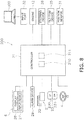
- FIG. 8 is a schematic diagram of a control system 200 for the outboard motor 2 according to a modification.
- the control system 200 may include an input port 32 to which a signal is inputted from an external machine 300.
- the external machine 300 is a computer device such as a PC (Personal Computer).
- the input port 32 receives the signal from the external machine 300 through wired or wireless communication.
- the controller 21 receives the signal from the external machine 300 through the input port 32.
- the external machine 300 causes the display 28 thereof to display the aforementioned setting screen 40 for setting the motion range.
- the motion range is set as described above by either a user or a dealer through the operation of the external machine 300.
- the external machine 300 may include a pointing device, for instance, and either the upper limit setting button 41 or the lower limit setting button 42 may be operated through the pointing device.
- the external machine 300 outputs a setting signal indicating the setting of the motion range, and the controller 21 receives the setting signal through the input port 32.
- the motion range of the tilt-trim motion under the automatic control mode may be set by operating the external machine 300.
Landscapes
- Chemical & Material Sciences (AREA)
- Engineering & Computer Science (AREA)
- Combustion & Propulsion (AREA)
- Mechanical Engineering (AREA)
- Ocean & Marine Engineering (AREA)
- Combined Controls Of Internal Combustion Engines (AREA)
Claims (11)
- Ein Neigungs-Trimm-System (100; 200) für einen Außenbordmotor (2), wobei das Neigungs-Trimm-System umfasst:eine Neigungs-Trimm-Vorrichtung (25), die konfiguriert ist, den Außenbordmotor (2) eine Neigungs-Trimm-Bewegung durchführen zu lassen;einen Betriebsschalter (23), der konfiguriert ist, die Neigungs-Trimm-Vorrichtung (25) zu betreiben;einen Sensor (31), der konfiguriert ist, eine Position des Außenbordmotors (2) während der Neigungs-Trimm-Bewegung zu detektieren, undeinen Controller (21), der mit der Neigungs-Trimm-Vorrichtung (25) und dem Betriebsschalter (23) verbunden ist, wobei der Controller (21) konfiguriert ist,zu bestimmen, ob ein Betrieb des Betriebsschalters (23) eine Vielzahl von Malen innerhalb einer vorgegebenen Zeitperiode durchgeführt wurde oder nicht, wenn ein Signal, das den Betrieb anzeigt, von dem Betriebsschalter (23) empfangen wird,konfiguriert ist, die Neigungs-Trimm-Vorrichtung (25) unter einem automatischen Steuermodus zu steuern, sodass die Neigungs-Trimm-Vorrichtung (25) den Außenbordmotor (2) die Neigungs-Trimm-Bewegung kontinuierlich innerhalb eines Bewegungsbereichs, der vorab eingestellt wurde, automatisch durchführen lässt, wenn der Betrieb die Vielzahl von Malen innerhalb der vorgegebenen Zeitperiode durchgeführt wurde,konfiguriert ist, ein Signal, das die Position des Außenbordmotors (2) anzeigt, von dem Sensor (31) während der Neigungs-Trimm-Bewegung unter dem automatischen Steuermodus zu empfangen,konfiguriert ist, die Neigungs-Trimm-Vorrichtung (25) zu deaktivieren, wenn der Außenbordmotor (2) entweder eine vorgegebene obere Grenze oder eine vorgegebene untere Grenze des Bewegungsbereichs erreicht, undkonfiguriert ist, den Bewegungsbereich in Einklang mit einem Stellsignal zum Stellen des Bewegungsbereichs zu ändern, wenn das Stellsignal empfangen wird.
- Ein Neigungs-Trimm-System (200) für einen Außenbordmotor (2) nach Anspruch 1, weiterhin umfassend:
einen Eingangsport (32), an den ein Signal von einer externen Maschine (300) eingegeben wird, wobei der Controller (21) konfiguriert ist, das Stellsignal durch den Eingangsport (32) zu empfangen. - Ein Neigungs-Trimm-System (100; 200) für einen Außenbordmotor (2) nach Anspruch 1, wobei der Controller (21) weiterhin konfiguriert ist, die Neigungs-Trimm-Vorrichtung (25) zu deaktivieren, wenn der Betrieb des Betriebsschalters (23) während der Neigungs-Trimm-Bewegung des Außenbordmotors (2) unter dem automatischen Steuermodus detektiert wird.
- Ein Neigungs-Trimm-System (100; 200) für einen Außenbordmotor (2) nach Anspruch 1, wobei
der Controller (21) weiterhin konfiguriert ist, die Neigungs-Trimm-Vorrichtung (25) zu deaktivieren, wenn ein Änderungswert in der Position des Außenbordmotors (2) innerhalb einer vorgegebenen Zeitperiode weniger als oder gleich einem vorgegebenen Grenzwert (Th1) ist. - Ein Neigungs-Trimm-System (100; 200) für einen Außenbordmotor (2) nach Anspruch 1, weiterhin umfassend:eine Alarmvorrichtung (29), wobeider Controller (21) weiterhin konfiguriert ist, die Alarmvorrichtung (29) zu steuern, einen Alarm während der Neigungs-Trimm-Bewegung des Außenbordmotors (2) unter dem automatischen Steuermodus auszugeben.
- Ein Neigungs-Trimm-System (100; 200) für einen Außenbordmotor (2) nach Anspruch 1, wobeider Außenbordmotor (2) einen Motor (12) beinhaltet,der Controller (21) weiterhin konfiguriert ist, zu bestimmen, ob der Motor (12) angetrieben wird oder nicht, undkonfiguriert ist, Starten des automatischen Steuermodus zurückzuhalten, wenn der Motor (12) angetrieben wird, sogar wenn der Betrieb die Vielzahl von Malen innerhalb der vorgegebenen Zeitperiode durchgeführt wurde.
- Ein Verfahren des Steuerns einer Neigungs-Trimm-Vorrichtung (25), die einen Außenbordmotor (2) eine Neigungs-Trimm-Bewegung durchführen lässt, wobei das Verfahren umfasst:Empfangen eines Signals, das einen Betrieb eines Betriebsschalters (23) zum Betreiben der Neigungs-Trimm-Vorrichtung (25) anzeigt;Bestimmen, ob der Betrieb eine Vielzahl von Malen innerhalb einer vorgegebenen Zeitperiode durchgeführt wurde oder nicht;Steuern der Neigungs-Trimm-Vorrichtung (25) unter einem automatischen Steuermodus, sodass die Neigungs-Trimm-Vorrichtung (25) den Außenbordmotor (2) die Neigungs-Trimm-Bewegung kontinuierlich innerhalb eines Bewegungsbereichs, der vorab eingestellt wurde, automatisch durchführen lässt, wenn der Betrieb die Vielzahl von Malen innerhalb der vorgegebenen Zeitperiode durchgeführt wurde;Deaktivieren der Neigungs-Trimm-Vorrichtung (25), wenn der Außenbordmotor (2) entweder eine vorgegebene obere Grenze oder eine vorgegebene untere Grenze des Bewegungsbereichs erreicht; undÄndern des Bewegungsbereichs in Einklang mit einem Stellsignal zum Stellen des Bewegungsbereichs, wenn das Stellsignal empfangen wird.
- Ein Verfahren nach Anspruch 7, weiterhin umfassend:
Deaktivieren der Neigungs-Trimm-Vorrichtung (25), wenn der Betrieb des Betriebsschalters (23) während der Neigungs-Trimm-Bewegung des Außenbordmotors (2) unter dem automatischen Steuermodus detektiert wurde. - Ein Verfahren nach Anspruch 7, weiterhin umfassend:Empfangen eines Signals, das eine Position des Außenbordmotors (2) während der Neigungs-Trimm-Bewegung unter dem automatischen Steuermodus anzeigt; undDeaktivieren der Neigungs-Trimm-Vorrichtung (25), wenn ein Änderungswert in der Position des Außenbordmotors (2) innerhalb einer vorgegebenen Zeitperiode weniger als oder gleich einem vorgegebenen Grenzwert (Th1) ist.
- Ein Verfahren nach Anspruch 7, weiterhin umfassend:
Ausgeben eines Kommandosignals, einen Alarm während der Neigungs-Trimm-Bewegung des Außenbordmotors (2) unter dem automatischen Steuermodus zu erteilen. - Ein Verfahren nach Anspruch 7, weiterhin umfassend:Bestimmen, ob ein Motor (12) des Außenbordmotors (2) angetrieben wird oder nicht; undZurückhalten des Startens des automatischen Steuermodus, wenn der Motor (12) angetrieben wird, sogar wenn der Betrieb die Vielzahl von Malen innerhalb der vorgegebenen Zeitperiode durchgeführt wurde.
Applications Claiming Priority (1)
| Application Number | Priority Date | Filing Date | Title |
|---|---|---|---|
| JP2018177914A JP2020049960A (ja) | 2018-09-21 | 2018-09-21 | 船外機のチルト・トリムシステム |
Publications (2)
| Publication Number | Publication Date |
|---|---|
| EP3626599A1 EP3626599A1 (de) | 2020-03-25 |
| EP3626599B1 true EP3626599B1 (de) | 2021-11-17 |
Family
ID=67956523
Family Applications (1)
| Application Number | Title | Priority Date | Filing Date |
|---|---|---|---|
| EP19197215.7A Active EP3626599B1 (de) | 2018-09-21 | 2019-09-13 | Neigungstrimmeinstellungssystem für einen aussenbordmotor |
Country Status (3)
| Country | Link |
|---|---|
| US (1) | US10625837B2 (de) |
| EP (1) | EP3626599B1 (de) |
| JP (1) | JP2020049960A (de) |
Families Citing this family (7)
| Publication number | Priority date | Publication date | Assignee | Title |
|---|---|---|---|---|
| US11372411B1 (en) | 2019-08-08 | 2022-06-28 | Brunswick Corporation | Marine steering system and method |
| JP7375689B2 (ja) * | 2020-06-26 | 2023-11-08 | 株式会社豊田自動織機 | 船舶用操舵装置 |
| US12033625B2 (en) | 2021-06-16 | 2024-07-09 | Roku, Inc. | Voice control device with push-to-talk (PTT) and mute controls |
| US12065230B1 (en) | 2022-02-15 | 2024-08-20 | Brunswick Corporation | Marine propulsion control system and method with rear and lateral marine drives |
| US12110088B1 (en) | 2022-07-20 | 2024-10-08 | Brunswick Corporation | Marine propulsion system and method with rear and lateral marine drives |
| US12258115B2 (en) | 2022-07-20 | 2025-03-25 | Brunswick Corporation | Marine propulsion system and joystick control method |
| US12134454B1 (en) | 2022-07-20 | 2024-11-05 | Brunswick Corporation | Marine propulsion system and method with single rear drive and lateral marine drive |
Family Cites Families (8)
| Publication number | Priority date | Publication date | Assignee | Title |
|---|---|---|---|---|
| JPH0657559B2 (ja) * | 1986-06-06 | 1994-08-03 | 三信工業株式会社 | 船舶推進機の傾動装置 |
| JPH0299493A (ja) * | 1988-10-04 | 1990-04-11 | Sanshin Ind Co Ltd | 船舶用推進ユニットのトリム・チルト装置 |
| US6220905B1 (en) * | 1999-12-10 | 2001-04-24 | Outboard Marine Corporation | Tilt-trim subsystem for marine propulsion systems |
| US6994046B2 (en) * | 2003-10-22 | 2006-02-07 | Yamaha Hatsudoki Kabushiki Kaisha | Marine vessel running controlling apparatus, marine vessel maneuvering supporting system and marine vessel each including the marine vessel running controlling apparatus, and marine vessel running controlling method |
| JP5742269B2 (ja) | 2011-02-09 | 2015-07-01 | スズキ株式会社 | 船外機の制御装置、最適トリム角の学習方法及びプログラム |
| JP2014024501A (ja) | 2012-07-30 | 2014-02-06 | Yamaha Motor Co Ltd | 船外機 |
| US10518856B2 (en) * | 2015-06-23 | 2019-12-31 | Brunswick Corporation | Systems and methods for automatically controlling attitude of a marine vessel with trim devices |
| US9919781B1 (en) * | 2015-06-23 | 2018-03-20 | Brunswick Corporation | Systems and methods for automatically controlling attitude of a marine vessel with trim devices |
-
2018
- 2018-09-21 JP JP2018177914A patent/JP2020049960A/ja active Pending
-
2019
- 2019-06-17 US US16/443,218 patent/US10625837B2/en active Active
- 2019-09-13 EP EP19197215.7A patent/EP3626599B1/de active Active
Also Published As
| Publication number | Publication date |
|---|---|
| JP2020049960A (ja) | 2020-04-02 |
| US10625837B2 (en) | 2020-04-21 |
| EP3626599A1 (de) | 2020-03-25 |
| US20200094932A1 (en) | 2020-03-26 |
Similar Documents
| Publication | Publication Date | Title |
|---|---|---|
| EP3626599B1 (de) | Neigungstrimmeinstellungssystem für einen aussenbordmotor | |
| US12545390B2 (en) | Bidirectional wireless controls for marine devices | |
| US11746497B2 (en) | Shovel | |
| EP3406516B1 (de) | Schiffmanövriervorrichtung und schiff damit | |
| US9663211B2 (en) | Boat maneuvering system | |
| EP3273037B1 (de) | Schaufel | |
| US11046407B2 (en) | System and method for positioning a jack plate coupled to a transom of a marine vessel | |
| EP2208631A1 (de) | Motordrehzahlsteuerungssystem für eine Baumaschine | |
| US20210025127A1 (en) | System and method for controlling bulldozer | |
| US12305366B2 (en) | Shovel | |
| US9156533B2 (en) | Control for trimming elements | |
| US20230294809A1 (en) | Remote trolling motor steering control | |
| EP4201806A1 (de) | Wasserfahrzeugantriebssteuerungssystem und -verfahren sowie wasserfahrzeug | |
| JP7716158B1 (ja) | 船舶の制御装置、船舶の制御方法、およびプログラム | |
| US20160237642A1 (en) | System and method for controlling position of machine implement | |
| JP5109198B2 (ja) | 産業車両用データ通信システムの動作切替装置 | |
| EP4086162B1 (de) | Schiffsmanövriersystem | |
| EP4606692A1 (de) | Bootsteuerungssystem und boot | |
| EP4491502A1 (de) | Schiffsantriebssystem | |
| EP4629019A1 (de) | Schiffssteuerungsvorrichtung, schiffssteuerungsverfahren und schiffssteuerungsprogramm | |
| CN120621647A (zh) | 推进装置控制系统和航行辅助装置 | |
| JPH1090010A (ja) | 作業機械の表示装置 | |
| JP5775431B2 (ja) | 産業車両用データ通信システムのモード切替装置 | |
| JPH05302574A (ja) | 油圧ポンプの制御装置 | |
| CN119072437A (zh) | 控制方法、显示装置、水域推进系统、设备及存储介质 |
Legal Events
| Date | Code | Title | Description |
|---|---|---|---|
| PUAI | Public reference made under article 153(3) epc to a published international application that has entered the european phase |
Free format text: ORIGINAL CODE: 0009012 |
|
| STAA | Information on the status of an ep patent application or granted ep patent |
Free format text: STATUS: THE APPLICATION HAS BEEN PUBLISHED |
|
| AK | Designated contracting states |
Kind code of ref document: A1 Designated state(s): AL AT BE BG CH CY CZ DE DK EE ES FI FR GB GR HR HU IE IS IT LI LT LU LV MC MK MT NL NO PL PT RO RS SE SI SK SM TR |
|
| AX | Request for extension of the european patent |
Extension state: BA ME |
|
| STAA | Information on the status of an ep patent application or granted ep patent |
Free format text: STATUS: REQUEST FOR EXAMINATION WAS MADE |
|
| 17P | Request for examination filed |
Effective date: 20200923 |
|
| RBV | Designated contracting states (corrected) |
Designated state(s): AL AT BE BG CH CY CZ DE DK EE ES FI FR GB GR HR HU IE IS IT LI LT LU LV MC MK MT NL NO PL PT RO RS SE SI SK SM TR |
|
| GRAP | Despatch of communication of intention to grant a patent |
Free format text: ORIGINAL CODE: EPIDOSNIGR1 |
|
| STAA | Information on the status of an ep patent application or granted ep patent |
Free format text: STATUS: GRANT OF PATENT IS INTENDED |
|
| INTG | Intention to grant announced |
Effective date: 20210723 |
|
| GRAS | Grant fee paid |
Free format text: ORIGINAL CODE: EPIDOSNIGR3 |
|
| GRAA | (expected) grant |
Free format text: ORIGINAL CODE: 0009210 |
|
| STAA | Information on the status of an ep patent application or granted ep patent |
Free format text: STATUS: THE PATENT HAS BEEN GRANTED |
|
| AK | Designated contracting states |
Kind code of ref document: B1 Designated state(s): AL AT BE BG CH CY CZ DE DK EE ES FI FR GB GR HR HU IE IS IT LI LT LU LV MC MK MT NL NO PL PT RO RS SE SI SK SM TR |
|
| REG | Reference to a national code |
Ref country code: GB Ref legal event code: FG4D |
|
| REG | Reference to a national code |
Ref country code: IE Ref legal event code: FG4D |
|
| REG | Reference to a national code |
Ref country code: DE Ref legal event code: R096 Ref document number: 602019009328 Country of ref document: DE |
|
| REG | Reference to a national code |
Ref country code: AT Ref legal event code: REF Ref document number: 1447843 Country of ref document: AT Kind code of ref document: T Effective date: 20211215 |
|
| REG | Reference to a national code |
Ref country code: LT Ref legal event code: MG9D |
|
| REG | Reference to a national code |
Ref country code: NL Ref legal event code: MP Effective date: 20211117 |
|
| REG | Reference to a national code |
Ref country code: AT Ref legal event code: MK05 Ref document number: 1447843 Country of ref document: AT Kind code of ref document: T Effective date: 20211117 |
|
| PG25 | Lapsed in a contracting state [announced via postgrant information from national office to epo] |
Ref country code: RS Free format text: LAPSE BECAUSE OF FAILURE TO SUBMIT A TRANSLATION OF THE DESCRIPTION OR TO PAY THE FEE WITHIN THE PRESCRIBED TIME-LIMIT Effective date: 20211117 Ref country code: LT Free format text: LAPSE BECAUSE OF FAILURE TO SUBMIT A TRANSLATION OF THE DESCRIPTION OR TO PAY THE FEE WITHIN THE PRESCRIBED TIME-LIMIT Effective date: 20211117 Ref country code: FI Free format text: LAPSE BECAUSE OF FAILURE TO SUBMIT A TRANSLATION OF THE DESCRIPTION OR TO PAY THE FEE WITHIN THE PRESCRIBED TIME-LIMIT Effective date: 20211117 Ref country code: BG Free format text: LAPSE BECAUSE OF FAILURE TO SUBMIT A TRANSLATION OF THE DESCRIPTION OR TO PAY THE FEE WITHIN THE PRESCRIBED TIME-LIMIT Effective date: 20220217 Ref country code: AT Free format text: LAPSE BECAUSE OF FAILURE TO SUBMIT A TRANSLATION OF THE DESCRIPTION OR TO PAY THE FEE WITHIN THE PRESCRIBED TIME-LIMIT Effective date: 20211117 |
|
| PG25 | Lapsed in a contracting state [announced via postgrant information from national office to epo] |
Ref country code: IS Free format text: LAPSE BECAUSE OF FAILURE TO SUBMIT A TRANSLATION OF THE DESCRIPTION OR TO PAY THE FEE WITHIN THE PRESCRIBED TIME-LIMIT Effective date: 20220317 Ref country code: SE Free format text: LAPSE BECAUSE OF FAILURE TO SUBMIT A TRANSLATION OF THE DESCRIPTION OR TO PAY THE FEE WITHIN THE PRESCRIBED TIME-LIMIT Effective date: 20211117 Ref country code: PT Free format text: LAPSE BECAUSE OF FAILURE TO SUBMIT A TRANSLATION OF THE DESCRIPTION OR TO PAY THE FEE WITHIN THE PRESCRIBED TIME-LIMIT Effective date: 20220317 Ref country code: PL Free format text: LAPSE BECAUSE OF FAILURE TO SUBMIT A TRANSLATION OF THE DESCRIPTION OR TO PAY THE FEE WITHIN THE PRESCRIBED TIME-LIMIT Effective date: 20211117 Ref country code: NO Free format text: LAPSE BECAUSE OF FAILURE TO SUBMIT A TRANSLATION OF THE DESCRIPTION OR TO PAY THE FEE WITHIN THE PRESCRIBED TIME-LIMIT Effective date: 20220217 Ref country code: NL Free format text: LAPSE BECAUSE OF FAILURE TO SUBMIT A TRANSLATION OF THE DESCRIPTION OR TO PAY THE FEE WITHIN THE PRESCRIBED TIME-LIMIT Effective date: 20211117 Ref country code: LV Free format text: LAPSE BECAUSE OF FAILURE TO SUBMIT A TRANSLATION OF THE DESCRIPTION OR TO PAY THE FEE WITHIN THE PRESCRIBED TIME-LIMIT Effective date: 20211117 Ref country code: HR Free format text: LAPSE BECAUSE OF FAILURE TO SUBMIT A TRANSLATION OF THE DESCRIPTION OR TO PAY THE FEE WITHIN THE PRESCRIBED TIME-LIMIT Effective date: 20211117 Ref country code: GR Free format text: LAPSE BECAUSE OF FAILURE TO SUBMIT A TRANSLATION OF THE DESCRIPTION OR TO PAY THE FEE WITHIN THE PRESCRIBED TIME-LIMIT Effective date: 20220218 Ref country code: ES Free format text: LAPSE BECAUSE OF FAILURE TO SUBMIT A TRANSLATION OF THE DESCRIPTION OR TO PAY THE FEE WITHIN THE PRESCRIBED TIME-LIMIT Effective date: 20211117 |
|
| PG25 | Lapsed in a contracting state [announced via postgrant information from national office to epo] |
Ref country code: SM Free format text: LAPSE BECAUSE OF FAILURE TO SUBMIT A TRANSLATION OF THE DESCRIPTION OR TO PAY THE FEE WITHIN THE PRESCRIBED TIME-LIMIT Effective date: 20211117 Ref country code: SK Free format text: LAPSE BECAUSE OF FAILURE TO SUBMIT A TRANSLATION OF THE DESCRIPTION OR TO PAY THE FEE WITHIN THE PRESCRIBED TIME-LIMIT Effective date: 20211117 Ref country code: RO Free format text: LAPSE BECAUSE OF FAILURE TO SUBMIT A TRANSLATION OF THE DESCRIPTION OR TO PAY THE FEE WITHIN THE PRESCRIBED TIME-LIMIT Effective date: 20211117 Ref country code: EE Free format text: LAPSE BECAUSE OF FAILURE TO SUBMIT A TRANSLATION OF THE DESCRIPTION OR TO PAY THE FEE WITHIN THE PRESCRIBED TIME-LIMIT Effective date: 20211117 Ref country code: DK Free format text: LAPSE BECAUSE OF FAILURE TO SUBMIT A TRANSLATION OF THE DESCRIPTION OR TO PAY THE FEE WITHIN THE PRESCRIBED TIME-LIMIT Effective date: 20211117 Ref country code: CZ Free format text: LAPSE BECAUSE OF FAILURE TO SUBMIT A TRANSLATION OF THE DESCRIPTION OR TO PAY THE FEE WITHIN THE PRESCRIBED TIME-LIMIT Effective date: 20211117 |
|
| REG | Reference to a national code |
Ref country code: DE Ref legal event code: R097 Ref document number: 602019009328 Country of ref document: DE |
|
| PLBE | No opposition filed within time limit |
Free format text: ORIGINAL CODE: 0009261 |
|
| STAA | Information on the status of an ep patent application or granted ep patent |
Free format text: STATUS: NO OPPOSITION FILED WITHIN TIME LIMIT |
|
| 26N | No opposition filed |
Effective date: 20220818 |
|
| PG25 | Lapsed in a contracting state [announced via postgrant information from national office to epo] |
Ref country code: AL Free format text: LAPSE BECAUSE OF FAILURE TO SUBMIT A TRANSLATION OF THE DESCRIPTION OR TO PAY THE FEE WITHIN THE PRESCRIBED TIME-LIMIT Effective date: 20211117 |
|
| PG25 | Lapsed in a contracting state [announced via postgrant information from national office to epo] |
Ref country code: SI Free format text: LAPSE BECAUSE OF FAILURE TO SUBMIT A TRANSLATION OF THE DESCRIPTION OR TO PAY THE FEE WITHIN THE PRESCRIBED TIME-LIMIT Effective date: 20211117 |
|
| REG | Reference to a national code |
Ref country code: DE Ref legal event code: R119 Ref document number: 602019009328 Country of ref document: DE |
|
| PG25 | Lapsed in a contracting state [announced via postgrant information from national office to epo] |
Ref country code: MC Free format text: LAPSE BECAUSE OF FAILURE TO SUBMIT A TRANSLATION OF THE DESCRIPTION OR TO PAY THE FEE WITHIN THE PRESCRIBED TIME-LIMIT Effective date: 20211117 |
|
| REG | Reference to a national code |
Ref country code: CH Ref legal event code: PL |
|
| REG | Reference to a national code |
Ref country code: BE Ref legal event code: MM Effective date: 20220930 |
|
| PG25 | Lapsed in a contracting state [announced via postgrant information from national office to epo] |
Ref country code: LU Free format text: LAPSE BECAUSE OF NON-PAYMENT OF DUE FEES Effective date: 20220913 |
|
| P01 | Opt-out of the competence of the unified patent court (upc) registered |
Effective date: 20230527 |
|
| PG25 | Lapsed in a contracting state [announced via postgrant information from national office to epo] |
Ref country code: LI Free format text: LAPSE BECAUSE OF NON-PAYMENT OF DUE FEES Effective date: 20220930 Ref country code: IE Free format text: LAPSE BECAUSE OF NON-PAYMENT OF DUE FEES Effective date: 20220913 Ref country code: DE Free format text: LAPSE BECAUSE OF NON-PAYMENT OF DUE FEES Effective date: 20230401 Ref country code: CH Free format text: LAPSE BECAUSE OF NON-PAYMENT OF DUE FEES Effective date: 20220930 |
|
| PG25 | Lapsed in a contracting state [announced via postgrant information from national office to epo] |
Ref country code: BE Free format text: LAPSE BECAUSE OF NON-PAYMENT OF DUE FEES Effective date: 20220930 |
|
| PG25 | Lapsed in a contracting state [announced via postgrant information from national office to epo] |
Ref country code: HU Free format text: LAPSE BECAUSE OF FAILURE TO SUBMIT A TRANSLATION OF THE DESCRIPTION OR TO PAY THE FEE WITHIN THE PRESCRIBED TIME-LIMIT; INVALID AB INITIO Effective date: 20190913 |
|
| PG25 | Lapsed in a contracting state [announced via postgrant information from national office to epo] |
Ref country code: CY Free format text: LAPSE BECAUSE OF FAILURE TO SUBMIT A TRANSLATION OF THE DESCRIPTION OR TO PAY THE FEE WITHIN THE PRESCRIBED TIME-LIMIT Effective date: 20211117 |
|
| GBPC | Gb: european patent ceased through non-payment of renewal fee |
Effective date: 20230913 |
|
| PG25 | Lapsed in a contracting state [announced via postgrant information from national office to epo] |
Ref country code: MK Free format text: LAPSE BECAUSE OF FAILURE TO SUBMIT A TRANSLATION OF THE DESCRIPTION OR TO PAY THE FEE WITHIN THE PRESCRIBED TIME-LIMIT Effective date: 20211117 |
|
| PG25 | Lapsed in a contracting state [announced via postgrant information from national office to epo] |
Ref country code: GB Free format text: LAPSE BECAUSE OF NON-PAYMENT OF DUE FEES Effective date: 20230913 |
|
| PG25 | Lapsed in a contracting state [announced via postgrant information from national office to epo] |
Ref country code: GB Free format text: LAPSE BECAUSE OF NON-PAYMENT OF DUE FEES Effective date: 20230913 |
|
| PG25 | Lapsed in a contracting state [announced via postgrant information from national office to epo] |
Ref country code: MT Free format text: LAPSE BECAUSE OF FAILURE TO SUBMIT A TRANSLATION OF THE DESCRIPTION OR TO PAY THE FEE WITHIN THE PRESCRIBED TIME-LIMIT Effective date: 20211117 |
|
| PGFP | Annual fee paid to national office [announced via postgrant information from national office to epo] |
Ref country code: IT Payment date: 20250923 Year of fee payment: 7 |
|
| PGFP | Annual fee paid to national office [announced via postgrant information from national office to epo] |
Ref country code: FR Payment date: 20250922 Year of fee payment: 7 |
|
| PG25 | Lapsed in a contracting state [announced via postgrant information from national office to epo] |
Ref country code: TR Free format text: LAPSE BECAUSE OF FAILURE TO SUBMIT A TRANSLATION OF THE DESCRIPTION OR TO PAY THE FEE WITHIN THE PRESCRIBED TIME-LIMIT Effective date: 20211117 |