EP3626149B1 - Staubsauger - Google Patents
Staubsauger Download PDFInfo
- Publication number
- EP3626149B1 EP3626149B1 EP19194793.6A EP19194793A EP3626149B1 EP 3626149 B1 EP3626149 B1 EP 3626149B1 EP 19194793 A EP19194793 A EP 19194793A EP 3626149 B1 EP3626149 B1 EP 3626149B1
- Authority
- EP
- European Patent Office
- Prior art keywords
- vacuum cleaner
- cleaner device
- relative humidity
- temperature
- sampled
- Prior art date
- Legal status (The legal status is an assumption and is not a legal conclusion. Google has not performed a legal analysis and makes no representation as to the accuracy of the status listed.)
- Active
Links
Images



Classifications
-
- A—HUMAN NECESSITIES
- A47—FURNITURE; DOMESTIC ARTICLES OR APPLIANCES; COFFEE MILLS; SPICE MILLS; SUCTION CLEANERS IN GENERAL
- A47L—DOMESTIC WASHING OR CLEANING; SUCTION CLEANERS IN GENERAL
- A47L9/00—Details or accessories of suction cleaners, e.g. mechanical means for controlling the suction or for effecting pulsating action; Storing devices specially adapted to suction cleaners or parts thereof; Carrying-vehicles specially adapted for suction cleaners
- A47L9/28—Installation of the electric equipment, e.g. adaptation or attachment to the suction cleaner; Controlling suction cleaners by electric means
- A47L9/2805—Parameters or conditions being sensed
- A47L9/2826—Parameters or conditions being sensed the condition of the floor
-
- A—HUMAN NECESSITIES
- A47—FURNITURE; DOMESTIC ARTICLES OR APPLIANCES; COFFEE MILLS; SPICE MILLS; SUCTION CLEANERS IN GENERAL
- A47L—DOMESTIC WASHING OR CLEANING; SUCTION CLEANERS IN GENERAL
- A47L5/00—Structural features of suction cleaners
- A47L5/12—Structural features of suction cleaners with power-driven air-pumps or air-compressors, e.g. driven by motor vehicle engine vacuum
-
- A—HUMAN NECESSITIES
- A47—FURNITURE; DOMESTIC ARTICLES OR APPLIANCES; COFFEE MILLS; SPICE MILLS; SUCTION CLEANERS IN GENERAL
- A47L—DOMESTIC WASHING OR CLEANING; SUCTION CLEANERS IN GENERAL
- A47L9/00—Details or accessories of suction cleaners, e.g. mechanical means for controlling the suction or for effecting pulsating action; Storing devices specially adapted to suction cleaners or parts thereof; Carrying-vehicles specially adapted for suction cleaners
- A47L9/02—Nozzles
-
- A—HUMAN NECESSITIES
- A47—FURNITURE; DOMESTIC ARTICLES OR APPLIANCES; COFFEE MILLS; SPICE MILLS; SUCTION CLEANERS IN GENERAL
- A47L—DOMESTIC WASHING OR CLEANING; SUCTION CLEANERS IN GENERAL
- A47L9/00—Details or accessories of suction cleaners, e.g. mechanical means for controlling the suction or for effecting pulsating action; Storing devices specially adapted to suction cleaners or parts thereof; Carrying-vehicles specially adapted for suction cleaners
- A47L9/28—Installation of the electric equipment, e.g. adaptation or attachment to the suction cleaner; Controlling suction cleaners by electric means
- A47L9/2805—Parameters or conditions being sensed
Definitions
- the present invention relates to a vacuum cleaner device.
- Such a vacuum cleaner device can be used, e.g. in a household, for vacuum cleaning, sweeping (wet-vac) etc.
- wet spots e.g. liquid layers, e.g. due to a spilled liquid
- the floor area e.g. a carpet or a hard floor
- the owner/user can be alerted about the presence of liquids.
- the present invention improves on the contemporary art by disclosing a vacuum cleaner device configured to operate on a floor area (e.g. for removing, particularly collecting, dust and other small particles from said floor area), wherein the device comprises a suction duct and a temperature sensor for sampling an air temperature in the vicinity of the device (e.g. upon movement of the device on the floor area) as a function of time, wherein the temperature sensor is arranged in the suction duct or adjacent an opening of the suction duct. Further, the vacuum cleaner device comprises an analyzing unit configured to detect a wet spot on said floor area using said sampled air temperature as an input.
- a temperature sensor when the temperature sensor is arranged adjacent an opening of the suction duct, the temperature sensor is arranged such with respect to the suction duct (or with respect to said opening of the suction duct) that a suction effect generated by the suction duct is present at the location of the temperature sensor.
- a temperature sensor allows a very precise and reliable detection of wet spots.
- such a sensor can be more robust and less prone to contamination.
- such a temperature sensor can be mounted on the device at a location where it is more shielded from mechanical damage. This allows improving reliability and durability of the device according to the present invention. Since a temperature sensor usually comprises a faster response time (e.g. 2 s when using e.g.
- the device can move with a higher velocity on the floor area while still being able to detect wet spots. Furthermore, it can also detect smaller amounts of liquids.
- the wet spot to be detected by the vacuum cleaner device can be formed by a spilled liquid (forming e.g. a liquid layer on said floor area).
- the liquid can e.g. be water or a spilled beverage, but also urine (e.g. pet or child urine).
- the floor area can be a carpet or another floor type (e.g. hard floor), but can also be a grass area in other embodiments of the device (e.g. in case the device is a lawn mower etc.).
- the analyzing unit can be or can comprise an analyzing circuit (e.g. an integrated circuit) that is particularly adapted to detect the respective wet spot using the sampled temperature (and optionally relative humidity) or a computed slope of the sampled temperature or of the sampled relative humidity, wherein the slope of the sampled temperature is the derivative of the sampled temperature with respect to time. Likewise, the slope of the sampled relative humidity is the derivative of the sampled relative humidity with respect to time.
- the analyzing unit can also be or comprise a computer or processor on which an algorithm (software) is executed that is adapted to detect the wet spot as described herein.
- the vacuum cleaner device can be configured to be moved manually, but may also comprise a drive system (e.g. in case the device is a robotic vacuum cleaner device).
- the vacuum cleaner device is a robotic vacuum cleaner device that is configured to autonomously operate on said floor area.
- the robotic vacuum cleaner device comprises a drive system that is configured to move the device autonomously on said floor area.
- the drive system of the device can comprise rotatable wheels via which the device is supported on the floor area. At least one of the wheels can be driven by a motor of the drive system of the device. In an embodiment, a first wheel can be driven with a first motor and a second wheel with a second motor of the drive system. This also allows steering of the device in a simple manner. Other ways of steering and driving the device can also be used. For instance, alternatively (e.g. instead of wheels), the device can comprise continuous tracks for moving on the floor area or other elements for transferring a force generated by the motor(s) of the drive system of the vacuum cleaner device to the floor area.
- the vacuum cleaner device is configured to measure and/or control a velocity of the vacuum cleaner device with respect to the floor area. This velocity can optionally be used to determine a size (e.g. a diameter) of a detected wet spot.
- the slope of the sampled temperatures (or of the sampled relative humidity) can provide a more accurate detection signal.
- the raw signal i.e. the sampled temperature or sampled relative humidity, is preferably used according to an embodiment.
- the device may comprise an electronic control unit to control the drive system, particularly the respective motor (e.g. the first and the second motor), so that the device can move autonomously on said floor area.
- the device may further comprise a navigation system for determining the current location (e.g. coordinates) of the device on the floor area (e.g. upon moving on said floor area), and particularly for passing the current location to the electronic control unit.
- the analyzing unit is configured to detect the presence of a wet spot on the floor area in case the sampled air temperature shows a predefined temperature drop over a predefined period of time, or in case a slope of the sampled temperatures is negative and decreases below a predefined threshold.
- the temperature drop per period of time is larger than 0.2 °C/s.
- the temperature drop per period of time is in the range from 0.4 °C/s to 1 °C/s. Particularly, when approaching the wet spot, the slope will be negative, whereas when leaving the wet spot, it will be positive.
- the T slopes may be inverted. This case can be discriminated by performing an integrity check with the relative humidity sensor.
- the integrity of the derived information may be checked by analysing the total temperature drop.
- the total temperature drop is larger than 0.2 °C, most preferably, larger than 0.5 °C.
- the analyzing unit is configured to determine a beginning and an end of a wet spot.
- said beginning corresponds to a location on the floor area for which the analyzing unit determines an onset of a temperature drop of the sampled temperature or a negative slope of the sampled temperature, which slope is smaller than a predefined threshold
- said end corresponds to a location on the floor area for which the analyzing unit determines an onset of an increase of the sampled temperature or a positive slope of the sampled temperature, which positive slope is larger than a predefined threshold.
- the respective threshold is used to differentiate from noise and slower effects exhibiting a changing temperature (e.g. being near an open window or heat source, e.g. a radiator).
- a changing temperature e.g. being near an open window or heat source, e.g. a radiator.
- an upper limit is less important because it depends mainly on a response time of the sensor and a velocity of the vacuum cleaner device.
- the analyzing unit is configured to at least one of:
- said pre-defined time span corresponds to a given size (e.g. diameter) of a wet spot divided by the velocity of the vacuum cleaner device.
- the vacuum cleaner device comprises at least one relative humidity sensor for sampling a relative humidity of the air as a function of time in the vicinity of the vacuum cleaner device (e.g. upon movement of the device on the floor area).
- the analyzing unit is configured to detect a wet spot on said floor area using said sampled air temperature and said sampled relative humidity.
- the analyzing unit is configured to detect the presence of a wet spot on the floor area in case the sampled air temperature shows a predefined temperature drop over a predefined period of time (or a slope of the sampled temperature is negative and decreases below a predefined threshold) and the relative humidity shows a predefined increase over a predefined period of time (or a slope of the sampled relative humidity increases above a predefined threshold).
- the relative humidity (RH) increase per time unit is larger than 0.1 %RH/s.
- RH relative humidity
- it is in the range from 0.2 %RH/s to 0.5 %RH/s.
- the slope of the sampled relative humidity will be positive. Furthermore, when leaving the wet spot, the slope of the sampled relative humidity will be negative. Once such a slope is detected, the integrity of the derived information can be checked by analysing the total relative humidity (RH) increase, which is particularly assumed to be larger than 0.3 %RH, preferably larger than 0.5 %RH, in case of a wet spot.
- RH total relative humidity
- the analyzing unit is configured to determine a beginning and an end of a wet spot using the sampled relative humidity.
- said beginning corresponds to a location on the floor area for which the analyzing unit determines an onset of an increase of the sampled relative humidity or a positive slope of the sampled relative humidity, which slope is larger than a predefined threshold
- said end corresponds to a location on the floor area for which the analyzing unit determines an onset of a decrease of the sampled relative humidity or a negative slope of the sampled temperature, which slope is smaller than a predefined threshold.
- the respective threshold is used to differentiate from noise and slower effects of changing relative humidity (RH), e.g. being near to open window / entering the bath room.
- RH relative humidity
- An upper limit is less important because it depends mainly on a response time of the sensor and a velocity of the vacuum cleaner.
- the device comprises a housing having a bottom wall configured to face said floor area upon operation of the vacuum cleaner device on said floor area and a lateral wall (e.g. a circumferential lateral wall) that particularly extends from the bottom wall.
- the lateral wall may form a front side of the housing, wherein particularly the device is configured to move or to be moved with the front side ahead in a movement direction.
- the bottom wall comprises said opening of the suction duct, so that air can be sucked into the suction duct via said opening.
- the housing forms a head of the vacuum cleaner device that is manually movable on said floor area and comprises said opening of the suction duct so that air can be sucked into the suction duct / device via said head.
- the temperature sensor is mounted to the bottom wall or to the lateral wall of the housing or head of the vacuum cleaner device.
- the temperature sensor can be mounted to the front side of the housing or head of the vacuum cleaner device.
- the temperature sensor comprises a distance to the floor area when the device rests on the floor area that is in the range from 1 mm to 100 mm.
- the at least one relative humidity sensor is mounted to the bottom wall or to the lateral wall. Particularly, the at least one relative humidity sensor is mounted to the front side. Particularly, in an embodiment, the at least one relative humidity sensor comprises a distance to the floor area when the device rests on the floor area that is in the range from 1 mm to 100 mm.
- the at least one relative humidity sensor can also be arranged in a suction duct or a hose of the vacuum cleaner device (e.g. in case of a car vacuum cleaner or an industrial vacuum cleaner).
- the suction duct comprises a constriction (e.g. a portion having a reduced inner diameter), wherein the temperature sensor is arranged in the constriction.
- the at least one relative humidity sensor is arranged in the suction duct. Due to such an arrangement of the relative humidity sensor, the latter is less exposed to mechanical damage.
- the at least one relative humidity sensor is arranged in the suction duct downstream a filter for filtering particles that is arranged in the suction duct.
- the filter is arranged downstream the temperature sensor.
- a robotic device that has the single function of detecting a wet spot on the floor area.
- the device does not comprise an additional function such as vacuum cleaning or mowing but is exclusively dedicated to monitoring or detecting wet spots on said floor area using the temperature sensor and particularly relative humidity sensor as described herein.
- the vacuum cleaner device when the vacuum cleaner device detects a wet spot, the vacuum cleaner device is configured to at least one of: stop, move around the wet spot, clean up the wet spot (e.g. by sucking up a liquid forming the wet spot, e.g. through the suction duct, or by drying or removing the wet spot in another fashion), store a location of the wet spot in a data storage of the robotic device, output a warning signal (e.g. acoustic and/or optical warning signal).
- a warning signal e.g. acoustic and/or optical warning signal
- a user can look up the location (e.g., using a smart phone app) to allow the user to find the spot even after it has dried / been removed.
- the analyzing unit is configured to determine a size (e.g. a diameter) of a detected wet spot (or a size/diameter of a region of the floor area covered by the wet spot). Further, particularly the analyzing unit is configured to alert a user in case said size exceeds a pre-defined threshold.
- a size e.g. a diameter
- the analyzing unit is configured to alert a user in case said size exceeds a pre-defined threshold.
- larger wet spots e.g. due to an appliance leak
- smaller wet spots e.g. due to pet urine etc.
- the analyzing unit is configured to use the velocity of the device with respect to the floor area to determine said size (e.g. diameter) of the wet spot on the floor area.
- the analyzing unit can be configured to determine said size (e.g. diameter) of the wet spot using a velocity of the vacuum cleaner device in a movement direction of the vacuum cleaner device as well as a determined location of a beginning of the wet spot and a determined location of an end of the wet spot along the movement direction of the vacuum cleaner device.
- the distance between the two temperature sensors can be used for determining the size of the wet spot.
- the vacuum cleaner device comprises at least one further temperature sensor configured to sample an air temperature in the vicinity of the device, wherein the at least one further temperature sensor is arranged in a further suction duct of the vacuum cleaner device.
- the temperature sensor is arranged in a first branch of the suction duct and the at least one further temperature sensor is arranged in a second branch of the suction duct.
- the analysing unit is configured to detect a wet spot on said floor area using said sampled air temperature sampled by the temperature sensor and said sampled air temperature sampled by the at least one further temperature sensor.
- the analyzing unit is configured to determine a location and/or dimension of the wet spot using the temperatures sampled by the temperature sensor and the at least one further temperature sensor.
- a computer-implemented method for detecting a wet spot comprising the steps of:
- the temperature drop per period of time is larger than 0.2 °C/s.
- the temperature drop per period of time is in the range from 0.4°C/s to 1 °C/s.
- the method further comprises the step of receiving a time series of a relative humidity of air located above the floor area.
- the step of detecting the presence of a wet spot corresponds to: detecting the presence of a wet spot on the floor area in case the air temperature shows a pre-defined temperature drop over a pre-defined period of time or in case the slope of the air temperature is negative and decreases below a predefined threshold, and in case the relative humidity shows a predefined increase over a predefined period of time or a slope of the relative humidity increases above a predefined threshold.
- the relative humidity (RH) increase per time unit is larger than 0.1 %RH/s.
- RH relative humidity
- it is in the range from 0.2 %RH/s to 0.5 %RH/s.
- the method further comprises at least one of following steps: determining if the temperature drop is followed by an increase of the temperature after passing of a pre-defined time span to confirm detection of the wet spot; determining if the relative humidity increases when the temperature drop occurs and/or decreases when said increase of the temperature (after passing of said pre-defined time span) occurs to confirm detection of the wet spot; determining if a total temperature drop associated with the detected wet spot exceeds a pre-defined threshold to confirm detection of the wet spot; determining if a total relative humidity increase associated with the detected wet spot exceeds a pre-defined threshold to confirm detection of the wet spot.
- the method may further comprise the step of receiving a velocity of a vacuum cleaner device and determining a size of a detected wet spot in a movement direction of a vacuum cleaner device using the velocity, as well as a location of a beginning of the detected wet spot and a location of an end of the detected wet spot with respect to the movement direction.
- said location of the beginning of the detected wet spot is determined as a location at which the temperature shows an onset of a drop in the temperature or a negative slope of the temperature, which slope is smaller than a predefined threshold; or as a location at which the relative humidity shows an onset of an increase of the relative humidity or a positive slope of the relative humidity, which slope is larger than a predefined threshold.
- said location of an end of the detected wet spot is determined as a location at which the temperature shows an onset of an increase of the sampled temperature or a positive slope of the sampled temperature, which positive slope is larger than a predefined threshold; or as a location at which the relative humidity shows an onset of a decrease in the relative humidity or a negative slope of the relative humidity, which slope is smaller than a predefined threshold.
- a non-transitory computer readable medium having stored thereon instructions that will cause a processor (e.g. a processor comprised by the analyzing unit of the vacuum cleaner device) to conduct the above-described method.
- Fig. 1 shows a vacuum cleaner device 1 for operation on a floor area F, wherein the device 1 comprises a suction duct 7 and an actuator 9 (e.g. a ventilator) that is configured to generate an underpressure in the suction duct 7 so that air is sucked into the suction duct 7. Further, the device 1 comprises a temperature sensor 10 configured to sample an air temperature in the vicinity of the device 1, wherein said temperature sensor 10 is arranged in the suction duct 7. Furthermore, the vacuum cleaner device 1 comprises an analyzing unit 3 configured to detect a wet spot W on said floor area F using said sampled air temperature.
- an actuator 9 e.g. a ventilator
- the device 1 comprise a head 6 having a bottom wall 6c configured to face said floor area F upon operation of the device 1 on said floor area F.
- the head 6 may comprise a circumferential lateral wall 6a extending from the bottom wall 6c.
- the temperature sensor 10 can also be arranged on the lateral wall 6a or on the bottom wall 6c, particularly in proximity to the opening 6c of the suction duct 7 so that the temperature sensor 10 is arranged in a region that experiences a suction effect generated by the suction duct 7 and actuator 9.
- the analyzing unit 3 analyzes the current air temperatures sampled with the temperature sensor 10 and concludes detection of a wet spot W in case the sampled air temperature drops by a predefined amount within a pre-defined period of time.
- At least one relative humidity sensor 11 can be arranged in the suction duct 7 (or on the head 6), wherein the at least one relative humidity sensor 11 can be used to confirm detection of the wet spot W, since the sampled relative humidities show an increase when the head 6 approaches a wet spot W (see also experimental data described below). Furthermore, as described above, a beginning B and an end E of the wet spot W with respect to the movement direction D can be detected (e.g. for determining a size/diameter of the wet spot W).
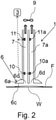
- Figure 2 shows a modification of the embodiment shown in Fig. 1 , wherein here the vacuum cleaner device 1 comprises two suction ducts 7, 7a, starting from an associated opening 6d formed in the bottom wall 6c of the head 6, wherein a temperature sensor 10, 10a is arranged in each suction duct 7, 7a. Furthermore, a relative humidity sensor 11, 11a can be arranged in each suction duct 7, 7a, too, in order to improve detection of wet spots W. In the embodiment shown in Fig. 2 , two temperature signals (and optionally relative humidity signals) can be used to determine the presence of a wet spot W as described above in conjunction with Fig. 1 .
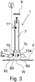
- Fig. 3 shows a further modification of the embodiment shown in Fig. 1 , wherein here the suction duct 7 branches off and comprises two branches 7b, 7c, wherein each branch 7b, 7c ends at its respective opening 6d formed in the bottom wall 6c of the head 6. Also here, two temperature signals (and optionally relative humidity signals) can be used to determine the presence of a wet spot W as described above in conjunction with Fig. 1 .
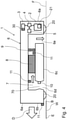
- Fig. 4 shows a further embodiment of a vacuum cleaner device 1 according to the present invention in form of a robotic vacuum cleaner device 1.
- a robotic device 1 can comprise a drive system 2 configured to move the device 1 autonomously on the floor area F, a temperature sensor 10 for sampling an air temperature in the vicinity of the device 1 (e.g. upon movement of the device 1 on the floor area F), and an analyzing unit 3 configured for detecting a wet spot W on said floor area F using said air temperature as an input, particularly when the device 1 approaches said wet spot W.
- the drive system 2 of the robotic device 1 can comprise rotatable wheels 20 via which the robotic device 20 is supported on the floor area F.
- a first wheel 20 can be driven with a first motor 21 and - similarly - a second wheel can be independently driven with a second motor (not shown) of the drive system 2 which also allows steering of the device 1 in a simple manner.
- Other ways of steering and driving the device 1 can also be used.
- the robotic device 1 can comprise an electronic control unit 4 to control the drive system 2, particularly the respective motor 20, so that the device 1 can move autonomously on said floor area F.
- the device 1 may further comprise a navigation system 5 for determining the current location (e.g. coordinates) of the robotic device 1 on the floor area F.
- the device 1 can further comprise a housing 6 having a bottom wall 6c configured to face said floor area F upon operation of the robotic device 1 on said floor area F. Further, the device 1 comprises a circumferential lateral wall 6a that also forms a front side 6b of the device when the device 1 moves in a movement direction D with the front side 6b ahead.
- the temperature sensor 10 can be mounted to the bottom wall 6c or to the lateral wall 6a, particularly to the front side 6b (wherein the temperature sensor 10 is preferably arranged in proximity to the opening 6d, see below, so that the temperature sensor 10 is arranged in a region where a suction effect/air flow generated by the device 1 is present). Particularly, in order to provide better protection of the temperature sensor 10, the latter is arranged in a suction duct 7 of the device 1 which is shown in Fig. 4 .
- the suction duct 7 can extend from an opening 6d formed in the bottom wall 6c of the housing 6 and may extend from said opening 6d forming an intake to an outtake opening 6e.
- the duct 7 may comprise a constriction 70, wherein particularly the temperature sensor 10 is arranged in the constriction 70.
- a filter 8 can be arranged in the suction duct 7 for filtering particles sucked into the suction duct 7 due to an underpressure generated by an actuator 9 (e.g. a ventilator) that can be arranged downstream the filter 8.
- an actuator 9 e.g. a ventilator
- the device 1 can comprise at least one or several (e.g. one to three) relative humidity sensors 11.
- the at least one relative humidity sensor 11 can also be mounted to the bottom wall 6c or to the lateral wall 6a, particularly to the front side 6b, as shown in Fig. 4 .
- the at least one relative humidity sensor 11 can also be arranged in the suction duct 7, as also shown in Fig. 4 , particularly, the at least one relative humidity sensor 11 can be arranged downstream the filter 8 and particularly upstream said actuator 9. In case the at least one relative humidity sensor 10 is arranged in the suction duct 7 it is less exposed to mechanical damage.
- the analyzing unit 3 analyzes the current air temperatures sampled with the temperature sensor 10 and concludes detection of a wet e.g. spot in case the sampled air temperature drops by a predefined amount within a pre-defined period of time.
- the slope of the sampled temperature and particularly other quantities related to temperature and/or relative humidity discussed above can be used to detect a wet spot W.
- the at least one relative humidity sensor 11 can be used to confirm detection of the wet spot W, since the sampled relative humidities show an increase when they approach the respective wet spot W (see also above).
- the vacuum cleaner device 1 detects a wet spot W
- the device 1 is configured to at least one of: stop, move around the wet spot W, remove the wet spot W, store a location of the wet spot W in a data storage 30 of the robotic device 1, output a warning signal (e.g. acoustic and/or optical warning signal).
- a warning signal e.g. acoustic and/or optical warning signal
- the device 1 allows a user to look up the location of the wet spot via an interface of the device (e.g. via a smart phone app) so that the user can find the wet spot even in case it has been removed by the device 1 for inspection.
- an interface of the device e.g. via a smart phone app
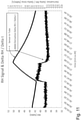
- Figs. 5 to 12 show experimental data recorded with temperature and relative humidity sensors that are located in the suction duct 7 of a vacuum cleaner device or on the head 6 (e.g. lateral side 6a).
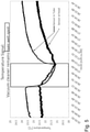
- Fig. 5 shows a temperature signal of a temperature sensor that is arranged in the suction duct 7 (denoted as tube) as well as a temperature signal of a temperature sensor 10 that is arranged outside the suction duct 7 on the head 6 of the vacuum cleaner device 1, wherein the head 6 has been moved over a wet spot W.
- Fig. 5 clearly shows the increase in the sampled temperature for both sensor locations.
- Fig. 6 shows a temperature signal of a temperature sensor that is arranged in the suction duct 7 as well as a temperature signal of a temperature sensor that is arranged outside the suction duct 7 on the head 6 of the vacuum cleaner device 1, wherein the signals are shown for four passes of the head 6 of the vacuum cleaner device 1 over the wet spot W.
- Fig. 6 demonstrates that a wet spot can also be detected when the device 1 is moving, since the respective signal shows a characteristic drop in case of a wet spot (here approx. at times 24:57, 25:06, 25:32, 25:49).
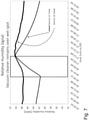
- Fig. 7 shows a relative humidity signal of a relative humidity sensor 11 that is arranged in the suction duct 7 (denoted as tube) as well as a relative humidity signal of a relative humidity sensor 11 that is arranged outside the suction duct 7 on the head 6 of the vacuum cleaner device 1, wherein the head 6 has been moved over a wet spot.
- the sampled relative humidity clearly increases for both sensor locations due to the wet spot.
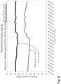
- Fig, 8 shows the signals of Fig. 7 in case the head 6 passes over the wet spot (here four such passes).
- Figures 9 to 12 show further experimental data to show that also the slope of the temperature signal (i.e. the sampled temperature) of a temperature sensor 10 or the slope of the relative humidity signal (i.e. the sampled relative humidity) of a relative humidity sensor 11 is a suitable detection signal for wet spots.
- the respective sensor 10, 11 is arranged in the suction duct 7 of a vacuum cleaner device 1 and the head 6 of the vacuum cleaner device 1 via which air is sucked into the suction duct 7 passes over the wet spot.
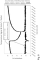
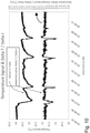
- Fig. 9 shows the temperature signal and its derivative with respect to time (i.e. the slope of the sampled temperature) for a single pass of the head 6 of the vacuum cleaner device 1 over the wet spot, while Fig. 10 shows four succeeding passes over the wet spot.
- Figs. 11 and 12 show the same situation for the relative humidity signal of a relative humidity sensor 11 that is arranged in the suction duct 7. Also Figs. 11 and 12 demonstrate that the relative humidity signal (sampled relative humidity) as well as the derivative of the relative humidity signal (i.e. the slope of the sampled relative humidity) can be used to detect wet spots.
Landscapes
- Engineering & Computer Science (AREA)
- Mechanical Engineering (AREA)
- Electric Vacuum Cleaner (AREA)
Claims (15)
- Staubsaugervorrichtung (1) zum Betrieb auf einer Bodenfläche (F), aufweisend:- einen Saugkanal (7) und einen Aktuator (9), der so angeordnet und konfiguriert ist, dass er einen Unterdruck in dem Saugkanal (7) erzeugt, so dass Luft in den Saugkanal (7) gesaugt wird,- einen Temperatursensor (10), der so konfiguriert ist, dass er eine Lufttemperatur in der Nähe der Vorrichtung (1) abtastet,dadurch gekennzeichnet, dass der Temperatursensor (10) im Ansaugkanal (7) oder in der Nähe einer Öffnung (6d) des Ansaugkanals (7) angeordnet ist, und wobei die Staubsaugervorrichtung (1) weiterhin eine Analyseeinheit (3) aufweist, die so konfiguriert ist, dass sie unter Verwendung der abgetasteten Lufttemperatur eine nasse Stelle (W) auf der Bodenfläche (F) erkennt.
- Die Staubsaugervorrichtung nach Anspruch 1, wobei die Analyseeinheit (3) so konfiguriert ist, dass sie das Vorhandensein eines nassen Flecks (W) auf der Bodenfläche (F) erkennt, wenn die abgetastete Lufttemperatur einen vordefinierten Temperaturabfall über eine vordefinierte Zeitspanne zeigt oder wenn eine Steigung der abgetasteten Lufttemperatur negativ ist und unter einen vordefinierten Schwellenwert abfällt.
- Staubsaugervorrichtung nach Anspruch 2, wobei der Temperaturabfall pro Zeitspanne größer als 0,2 °G/s ist, und/oder wobei der Temperaturabfall pro Zeitspanne im Bereich von 0,4°C/s bis 1 °C/s liegt.
- Staubsaugervorrichtung nach einem der vorhergehenden Ansprüche, wobei die Analyseeinheit (3) ferner konfiguriert ist, um mindestens eine der folgenden Maßnahmen vorzunehmen:Bestimmen, ob auf den Temperaturabfall ein Anstieg der abgetasteten Temperatur nach Ablauf einer vordefinierten Zeitspanne folgt, um die Erkennung des nassen Flecks (W) zu bestätigen; Bestimmen, ob eine von der Staubsaugervorrichtung (1) abgetastete relative Feuchtigkeit zunimmt, wenn der Temperaturabfall auftritt, und/oder abnimmt, wenn der Anstieg der abgetasteten Temperatur auftritt, um die Erkennung des nassen Flecks (W) zu bestätigen; Bestimmen, ob ein mit dem erkannten nassen Fleck (W) verbundener Gesamttemperaturabfall einen vordefinierten Schwellenwert überschreitet, um die Erkennung des nassen Flecks (W) zu bestätigen; Bestimmen, ob ein mit dem erkannten nassen Fleck (W) verbundener Gesamtanstieg der relativen Feuchtigkeit einen vordefinierten Schwellenwert überschreitet, um die Erkennung des nassen Flecks (W) zu bestätigen;
- Staubsaugervorrichtung nach einem der vorhergehenden Ansprüche, wobei die Staubsaugervorrichtung (1) mindestens einen Sensor zur Messung der relativen Feuchtigkeit (11) umfasst, der so konfiguriert ist, dass er eine relative Feuchtigkeit der Luft in der Umgebung der Staubsaugervorrichtung (1) abtastet.
- Staubsaugervorrichtung nach Anspruch 5, wobei die Analyseeinheit (3) so konfiguriert ist, dass sie unter Verwendung der abgetasteten Lufttemperatur und der abgetasteten relativen Luftfeuchtigkeit einen nassen Fleck (W) auf der Bodenfläche (F) erkennt.
- Staubsaugervorrichtung nach Anspruch 5 oder 6, wobei die Analyseeinheit (3) so konfiguriert ist, dass sie das Vorhandensein eines nassen Flecks (W) auf der Bodenfläche (F) erkennt, wenn die abgetastete Lufttemperatur einen vordefinierten Temperaturabfall über einen vordefinierten Zeitraum zeigt oder eine Steigung der abgetasteten Temperaturen negativ ist und unter einen vordefinierten Schwellenwert abfällt, und wenn die relative Luftfeuchtigkeit einen vordefinierten Anstieg über einen vordefinierten Zeitraum zeigt oder eine Steigung der abgetasteten relativen Luftfeuchtigkeit über einen vordefinierten Schwellenwert steigt.
- Staubsaugervorrichtung nach einem der vorhergehenden Ansprüche, wobei die Staubsaugervorrichtung (1) ein Gehäuse (6) mit einer Bodenwand (6c) umfasst, die so konfiguriert ist, dass sie bei Betrieb der Staubsaugervorrichtung (1) auf der Bodenfläche (F) der Bodenfläche (F) zugewandt ist, wobei die Bodenwand (6c) die Öffnung (6d) umfasst, und wobei das Gehäuse (6) eine Seitenwand (6a) umfasst.
- Staubsaugervorrichtung nach einem der vorhergehenden Ansprüche, wobei der Saugkanal (7) eine Verengung (70) aufweist, wobei der Temperatursensor (10) in der Verengung (70) angeordnet ist.
- Staubsaugervorrichtung nach Anspruch 8, wobei der Temperatursensor (10) an der Bodenwand (6c) oder an der Seitenwand (6a) angrenzend an die Öffnung (6d) angebracht ist.
- Staubsaugervorrichtung nach Anspruch 5 und nach Anspruch 8 oder 10, wobei der mindestens eine Sensor zur Messung der relativen Feuchtigkeit (11) an der Bodenwand (6c) angebracht ist oder an der Seitenwand (6a).
- Staubsaugervorrichtung nach Anspruch 5 oder nach einem der Ansprüche 6 bis 11 sofern rückbezogen auf Anspruch 5, wobei der mindestens eine Sensor zur Messung der relativen Feuchtigkeit (11) im Saugkanal (7) angeordnet ist.
- Staubsaugervorrichtung nach Anspruch 12, wobei der mindestens eine Sensor zur Messung der relativen Feuchtigkeit (11) im Saugkanal (7) stromabwärts eines im Saugkanal (7) angeordneten Filters (8) zum Filtern von Partikeln angeordnet ist.
- Staubsaugervorrichtung nach einem der vorhergehenden Ansprüche, wobei die Staub saugervorri chtung (1) eine Roboter-Staubsaugervorrichtung zum autonomen Betrieb auf der Bodenfläche (F) ist.
- Staubsaugervorrichtung nach Anspruch 14, wobei die Staubsaugervorrichtung (1) ein Antriebssystem (2) aufweist, das zum Bewegen der Staubsaugervorrichtung (1) ausgebildet ist.
Applications Claiming Priority (2)
| Application Number | Priority Date | Filing Date | Title |
|---|---|---|---|
| US16/116,959 US11259676B2 (en) | 2018-08-30 | 2018-08-30 | Vacuum cleaner device |
| EP18196706 | 2018-09-25 |
Publications (2)
| Publication Number | Publication Date |
|---|---|
| EP3626149A1 EP3626149A1 (de) | 2020-03-25 |
| EP3626149B1 true EP3626149B1 (de) | 2022-03-02 |
Family
ID=67840926
Family Applications (1)
| Application Number | Title | Priority Date | Filing Date |
|---|---|---|---|
| EP19194793.6A Active EP3626149B1 (de) | 2018-08-30 | 2019-08-30 | Staubsauger |
Country Status (2)
| Country | Link |
|---|---|
| EP (1) | EP3626149B1 (de) |
| CN (1) | CN110870717B (de) |
Families Citing this family (3)
| Publication number | Priority date | Publication date | Assignee | Title |
|---|---|---|---|---|
| US20250000321A1 (en) * | 2021-11-17 | 2025-01-02 | Tineco Intelligent Technology Co., Ltd. | Cleaning device and control method |
| CN114027742B (zh) * | 2021-11-17 | 2025-07-29 | 添可智能科技有限公司 | 清洗设备和检测装置 |
| CN114209256A (zh) * | 2021-11-17 | 2022-03-22 | 添可智能科技有限公司 | 清洁设备及控制方法 |
Family Cites Families (10)
| Publication number | Priority date | Publication date | Assignee | Title |
|---|---|---|---|---|
| JPH1189771A (ja) * | 1997-09-25 | 1999-04-06 | Mitsubishi Electric Corp | 電気掃除機 |
| KR100555319B1 (ko) | 2004-12-22 | 2006-03-03 | 삼성광주전자 주식회사 | 진공청소기용 집진장치 및 이를 이용한 집진방법 |
| WO2008007830A1 (en) | 2006-07-14 | 2008-01-17 | Hanulkid Co., Ltd. | Steam robot cleaner |
| ATE470005T1 (de) * | 2006-11-10 | 2010-06-15 | Johnson Diversey Inc | Sensorvorrichtung und verfahren |
| JP6068824B2 (ja) * | 2012-05-01 | 2017-01-25 | シャープ株式会社 | 自走式電子機器 |
| DE102014113040A1 (de) | 2014-09-10 | 2016-03-10 | Miele & Cie. Kg | Verfahren zum Betrieb eines Haushaltsgerätesystems |
| KR101659037B1 (ko) * | 2015-02-16 | 2016-09-23 | 엘지전자 주식회사 | 로봇 청소기, 이를 포함하는 원격 제어 시스템 및 이의 제어 방법 |
| DE102015106536B4 (de) * | 2015-04-28 | 2016-11-10 | Vorwerk & Co. Interholding Gmbh | Haushaltsroboter und Verfahren zum Betreiben eines Haushaltsroboters |
| JP6685755B2 (ja) * | 2016-02-16 | 2020-04-22 | 東芝ライフスタイル株式会社 | 自律走行体 |
| EP3241476A1 (de) * | 2016-05-03 | 2017-11-08 | Koninklijke Philips N.V. | Staubsauger |
-
2019
- 2019-08-29 CN CN201910806915.4A patent/CN110870717B/zh active Active
- 2019-08-30 EP EP19194793.6A patent/EP3626149B1/de active Active
Also Published As
| Publication number | Publication date |
|---|---|
| EP3626149A1 (de) | 2020-03-25 |
| CN110870717A (zh) | 2020-03-10 |
| CN110870717B (zh) | 2021-08-03 |
Similar Documents
| Publication | Publication Date | Title |
|---|---|---|
| CN106175600B (zh) | 控制移动式机器人的方法 | |
| JP7487283B2 (ja) | 自律移動ロボットのナビゲーション | |
| EP3626149A1 (de) | Staubsauger | |
| US20220039623A1 (en) | Autonomous vacuum operation in response to dirt detection | |
| US9015897B2 (en) | Dust detection system | |
| US9955839B2 (en) | Side brush for a robotic vacuum cleaner and robotic vacuum cleaner comprising a side brush | |
| CN114631069B (zh) | 自主移动机器人的控制 | |
| JP5075207B2 (ja) | 掃除機ノズル、及び吸引掃除に対する方法 | |
| CN114402366A (zh) | 自主移动机器人的地图绘制 | |
| KR102705170B1 (ko) | 로봇 청소기 및 이의 제어 방법 | |
| CN107580467B (zh) | 家用机器人和用于驱动家用机器人的方法 | |
| KR102147207B1 (ko) | 이동 로봇 및 그 제어방법 | |
| KR20180064966A (ko) | 청소 기능 제어 장치 및 이를 구비하는 청소 로봇 | |
| JP2003505127A5 (de) | ||
| US11259676B2 (en) | Vacuum cleaner device | |
| KR102201144B1 (ko) | 이동 로봇 및 그 제어방법 | |
| NL1026023C2 (nl) | Robotreiniger met vloerdesinfecterende functie. | |
| CN110121286A (zh) | 自走式移动体、湿度传感器及液体检测装置 | |
| CN108209744A (zh) | 清洁方法、装置、计算机设备和存储介质 | |
| KR102467990B1 (ko) | 로봇 청소기 | |
| CN109827592A (zh) | 一种扫地机器人被困的检测方法 | |
| KR20180085154A (ko) | 로봇청소기 | |
| CN104172991A (zh) | 自走式清洁设备污尘侦测方法及装置 | |
| CN109965786A (zh) | 一种清洁机器人及其避障方法 | |
| JP7345140B2 (ja) | 自走式掃除機 |
Legal Events
| Date | Code | Title | Description |
|---|---|---|---|
| PUAI | Public reference made under article 153(3) epc to a published international application that has entered the european phase |
Free format text: ORIGINAL CODE: 0009012 |
|
| STAA | Information on the status of an ep patent application or granted ep patent |
Free format text: STATUS: THE APPLICATION HAS BEEN PUBLISHED |
|
| AK | Designated contracting states |
Kind code of ref document: A1 Designated state(s): AL AT BE BG CH CY CZ DE DK EE ES FI FR GB GR HR HU IE IS IT LI LT LU LV MC MK MT NL NO PL PT RO RS SE SI SK SM TR |
|
| AX | Request for extension of the european patent |
Extension state: BA ME |
|
| STAA | Information on the status of an ep patent application or granted ep patent |
Free format text: STATUS: REQUEST FOR EXAMINATION WAS MADE |
|
| 17P | Request for examination filed |
Effective date: 20200925 |
|
| RBV | Designated contracting states (corrected) |
Designated state(s): AL AT BE BG CH CY CZ DE DK EE ES FI FR GB GR HR HU IE IS IT LI LT LU LV MC MK MT NL NO PL PT RO RS SE SI SK SM TR |
|
| GRAP | Despatch of communication of intention to grant a patent |
Free format text: ORIGINAL CODE: EPIDOSNIGR1 |
|
| STAA | Information on the status of an ep patent application or granted ep patent |
Free format text: STATUS: GRANT OF PATENT IS INTENDED |
|
| RIC1 | Information provided on ipc code assigned before grant |
Ipc: A47L 9/28 20060101AFI20210215BHEP |
|
| INTG | Intention to grant announced |
Effective date: 20210316 |
|
| GRAJ | Information related to disapproval of communication of intention to grant by the applicant or resumption of examination proceedings by the epo deleted |
Free format text: ORIGINAL CODE: EPIDOSDIGR1 |
|
| STAA | Information on the status of an ep patent application or granted ep patent |
Free format text: STATUS: REQUEST FOR EXAMINATION WAS MADE |
|
| INTC | Intention to grant announced (deleted) | ||
| GRAP | Despatch of communication of intention to grant a patent |
Free format text: ORIGINAL CODE: EPIDOSNIGR1 |
|
| STAA | Information on the status of an ep patent application or granted ep patent |
Free format text: STATUS: GRANT OF PATENT IS INTENDED |
|
| INTG | Intention to grant announced |
Effective date: 20210914 |
|
| GRAS | Grant fee paid |
Free format text: ORIGINAL CODE: EPIDOSNIGR3 |
|
| GRAA | (expected) grant |
Free format text: ORIGINAL CODE: 0009210 |
|
| STAA | Information on the status of an ep patent application or granted ep patent |
Free format text: STATUS: THE PATENT HAS BEEN GRANTED |
|
| AK | Designated contracting states |
Kind code of ref document: B1 Designated state(s): AL AT BE BG CH CY CZ DE DK EE ES FI FR GB GR HR HU IE IS IT LI LT LU LV MC MK MT NL NO PL PT RO RS SE SI SK SM TR |
|
| REG | Reference to a national code |
Ref country code: GB Ref legal event code: FG4D |
|
| REG | Reference to a national code |
Ref country code: CH Ref legal event code: EP Ref country code: AT Ref legal event code: REF Ref document number: 1471573 Country of ref document: AT Kind code of ref document: T Effective date: 20220315 |
|
| REG | Reference to a national code |
Ref country code: DE Ref legal event code: R096 Ref document number: 602019012048 Country of ref document: DE |
|
| REG | Reference to a national code |
Ref country code: IE Ref legal event code: FG4D |
|
| REG | Reference to a national code |
Ref country code: LT Ref legal event code: MG9D |
|
| REG | Reference to a national code |
Ref country code: NL Ref legal event code: MP Effective date: 20220302 |
|
| PG25 | Lapsed in a contracting state [announced via postgrant information from national office to epo] |
Ref country code: SE Free format text: LAPSE BECAUSE OF FAILURE TO SUBMIT A TRANSLATION OF THE DESCRIPTION OR TO PAY THE FEE WITHIN THE PRESCRIBED TIME-LIMIT Effective date: 20220302 Ref country code: RS Free format text: LAPSE BECAUSE OF FAILURE TO SUBMIT A TRANSLATION OF THE DESCRIPTION OR TO PAY THE FEE WITHIN THE PRESCRIBED TIME-LIMIT Effective date: 20220302 Ref country code: NO Free format text: LAPSE BECAUSE OF FAILURE TO SUBMIT A TRANSLATION OF THE DESCRIPTION OR TO PAY THE FEE WITHIN THE PRESCRIBED TIME-LIMIT Effective date: 20220602 Ref country code: LT Free format text: LAPSE BECAUSE OF FAILURE TO SUBMIT A TRANSLATION OF THE DESCRIPTION OR TO PAY THE FEE WITHIN THE PRESCRIBED TIME-LIMIT Effective date: 20220302 Ref country code: HR Free format text: LAPSE BECAUSE OF FAILURE TO SUBMIT A TRANSLATION OF THE DESCRIPTION OR TO PAY THE FEE WITHIN THE PRESCRIBED TIME-LIMIT Effective date: 20220302 Ref country code: ES Free format text: LAPSE BECAUSE OF FAILURE TO SUBMIT A TRANSLATION OF THE DESCRIPTION OR TO PAY THE FEE WITHIN THE PRESCRIBED TIME-LIMIT Effective date: 20220302 Ref country code: BG Free format text: LAPSE BECAUSE OF FAILURE TO SUBMIT A TRANSLATION OF THE DESCRIPTION OR TO PAY THE FEE WITHIN THE PRESCRIBED TIME-LIMIT Effective date: 20220602 |
|
| REG | Reference to a national code |
Ref country code: AT Ref legal event code: MK05 Ref document number: 1471573 Country of ref document: AT Kind code of ref document: T Effective date: 20220302 |
|
| PG25 | Lapsed in a contracting state [announced via postgrant information from national office to epo] |
Ref country code: PL Free format text: LAPSE BECAUSE OF FAILURE TO SUBMIT A TRANSLATION OF THE DESCRIPTION OR TO PAY THE FEE WITHIN THE PRESCRIBED TIME-LIMIT Effective date: 20220302 Ref country code: LV Free format text: LAPSE BECAUSE OF FAILURE TO SUBMIT A TRANSLATION OF THE DESCRIPTION OR TO PAY THE FEE WITHIN THE PRESCRIBED TIME-LIMIT Effective date: 20220302 Ref country code: GR Free format text: LAPSE BECAUSE OF FAILURE TO SUBMIT A TRANSLATION OF THE DESCRIPTION OR TO PAY THE FEE WITHIN THE PRESCRIBED TIME-LIMIT Effective date: 20220603 Ref country code: FI Free format text: LAPSE BECAUSE OF FAILURE TO SUBMIT A TRANSLATION OF THE DESCRIPTION OR TO PAY THE FEE WITHIN THE PRESCRIBED TIME-LIMIT Effective date: 20220302 |
|
| PG25 | Lapsed in a contracting state [announced via postgrant information from national office to epo] |
Ref country code: NL Free format text: LAPSE BECAUSE OF FAILURE TO SUBMIT A TRANSLATION OF THE DESCRIPTION OR TO PAY THE FEE WITHIN THE PRESCRIBED TIME-LIMIT Effective date: 20220302 |
|
| PG25 | Lapsed in a contracting state [announced via postgrant information from national office to epo] |
Ref country code: SM Free format text: LAPSE BECAUSE OF FAILURE TO SUBMIT A TRANSLATION OF THE DESCRIPTION OR TO PAY THE FEE WITHIN THE PRESCRIBED TIME-LIMIT Effective date: 20220302 Ref country code: SK Free format text: LAPSE BECAUSE OF FAILURE TO SUBMIT A TRANSLATION OF THE DESCRIPTION OR TO PAY THE FEE WITHIN THE PRESCRIBED TIME-LIMIT Effective date: 20220302 Ref country code: RO Free format text: LAPSE BECAUSE OF FAILURE TO SUBMIT A TRANSLATION OF THE DESCRIPTION OR TO PAY THE FEE WITHIN THE PRESCRIBED TIME-LIMIT Effective date: 20220302 Ref country code: PT Free format text: LAPSE BECAUSE OF FAILURE TO SUBMIT A TRANSLATION OF THE DESCRIPTION OR TO PAY THE FEE WITHIN THE PRESCRIBED TIME-LIMIT Effective date: 20220704 Ref country code: EE Free format text: LAPSE BECAUSE OF FAILURE TO SUBMIT A TRANSLATION OF THE DESCRIPTION OR TO PAY THE FEE WITHIN THE PRESCRIBED TIME-LIMIT Effective date: 20220302 Ref country code: CZ Free format text: LAPSE BECAUSE OF FAILURE TO SUBMIT A TRANSLATION OF THE DESCRIPTION OR TO PAY THE FEE WITHIN THE PRESCRIBED TIME-LIMIT Effective date: 20220302 Ref country code: AT Free format text: LAPSE BECAUSE OF FAILURE TO SUBMIT A TRANSLATION OF THE DESCRIPTION OR TO PAY THE FEE WITHIN THE PRESCRIBED TIME-LIMIT Effective date: 20220302 |
|
| PG25 | Lapsed in a contracting state [announced via postgrant information from national office to epo] |
Ref country code: IS Free format text: LAPSE BECAUSE OF FAILURE TO SUBMIT A TRANSLATION OF THE DESCRIPTION OR TO PAY THE FEE WITHIN THE PRESCRIBED TIME-LIMIT Effective date: 20220702 Ref country code: AL Free format text: LAPSE BECAUSE OF FAILURE TO SUBMIT A TRANSLATION OF THE DESCRIPTION OR TO PAY THE FEE WITHIN THE PRESCRIBED TIME-LIMIT Effective date: 20220302 |
|
| REG | Reference to a national code |
Ref country code: DE Ref legal event code: R097 Ref document number: 602019012048 Country of ref document: DE |
|
| PLBE | No opposition filed within time limit |
Free format text: ORIGINAL CODE: 0009261 |
|
| STAA | Information on the status of an ep patent application or granted ep patent |
Free format text: STATUS: NO OPPOSITION FILED WITHIN TIME LIMIT |
|
| PG25 | Lapsed in a contracting state [announced via postgrant information from national office to epo] |
Ref country code: DK Free format text: LAPSE BECAUSE OF FAILURE TO SUBMIT A TRANSLATION OF THE DESCRIPTION OR TO PAY THE FEE WITHIN THE PRESCRIBED TIME-LIMIT Effective date: 20220302 |
|
| 26N | No opposition filed |
Effective date: 20221205 |
|
| PG25 | Lapsed in a contracting state [announced via postgrant information from national office to epo] |
Ref country code: SI Free format text: LAPSE BECAUSE OF FAILURE TO SUBMIT A TRANSLATION OF THE DESCRIPTION OR TO PAY THE FEE WITHIN THE PRESCRIBED TIME-LIMIT Effective date: 20220302 |
|
| PG25 | Lapsed in a contracting state [announced via postgrant information from national office to epo] |
Ref country code: MC Free format text: LAPSE BECAUSE OF FAILURE TO SUBMIT A TRANSLATION OF THE DESCRIPTION OR TO PAY THE FEE WITHIN THE PRESCRIBED TIME-LIMIT Effective date: 20220302 |
|
| PG25 | Lapsed in a contracting state [announced via postgrant information from national office to epo] |
Ref country code: LU Free format text: LAPSE BECAUSE OF NON-PAYMENT OF DUE FEES Effective date: 20220830 |
|
| REG | Reference to a national code |
Ref country code: BE Ref legal event code: MM Effective date: 20220831 |
|
| P01 | Opt-out of the competence of the unified patent court (upc) registered |
Effective date: 20230602 |
|
| PG25 | Lapsed in a contracting state [announced via postgrant information from national office to epo] |
Ref country code: IT Free format text: LAPSE BECAUSE OF FAILURE TO SUBMIT A TRANSLATION OF THE DESCRIPTION OR TO PAY THE FEE WITHIN THE PRESCRIBED TIME-LIMIT Effective date: 20220302 Ref country code: IE Free format text: LAPSE BECAUSE OF NON-PAYMENT OF DUE FEES Effective date: 20220830 Ref country code: FR Free format text: LAPSE BECAUSE OF NON-PAYMENT OF DUE FEES Effective date: 20220831 |
|
| PG25 | Lapsed in a contracting state [announced via postgrant information from national office to epo] |
Ref country code: BE Free format text: LAPSE BECAUSE OF NON-PAYMENT OF DUE FEES Effective date: 20220831 |
|
| PG25 | Lapsed in a contracting state [announced via postgrant information from national office to epo] |
Ref country code: HU Free format text: LAPSE BECAUSE OF FAILURE TO SUBMIT A TRANSLATION OF THE DESCRIPTION OR TO PAY THE FEE WITHIN THE PRESCRIBED TIME-LIMIT; INVALID AB INITIO Effective date: 20190830 |
|
| PG25 | Lapsed in a contracting state [announced via postgrant information from national office to epo] |
Ref country code: CY Free format text: LAPSE BECAUSE OF FAILURE TO SUBMIT A TRANSLATION OF THE DESCRIPTION OR TO PAY THE FEE WITHIN THE PRESCRIBED TIME-LIMIT Effective date: 20220302 |
|
| PG25 | Lapsed in a contracting state [announced via postgrant information from national office to epo] |
Ref country code: MK Free format text: LAPSE BECAUSE OF FAILURE TO SUBMIT A TRANSLATION OF THE DESCRIPTION OR TO PAY THE FEE WITHIN THE PRESCRIBED TIME-LIMIT Effective date: 20220302 |
|
| PG25 | Lapsed in a contracting state [announced via postgrant information from national office to epo] |
Ref country code: MT Free format text: LAPSE BECAUSE OF FAILURE TO SUBMIT A TRANSLATION OF THE DESCRIPTION OR TO PAY THE FEE WITHIN THE PRESCRIBED TIME-LIMIT Effective date: 20220302 |
|
| PGFP | Annual fee paid to national office [announced via postgrant information from national office to epo] |
Ref country code: DE Payment date: 20250819 Year of fee payment: 7 |
|
| PGFP | Annual fee paid to national office [announced via postgrant information from national office to epo] |
Ref country code: GB Payment date: 20250822 Year of fee payment: 7 |
|
| PGFP | Annual fee paid to national office [announced via postgrant information from national office to epo] |
Ref country code: CH Payment date: 20250901 Year of fee payment: 7 |
|
| PG25 | Lapsed in a contracting state [announced via postgrant information from national office to epo] |
Ref country code: TR Free format text: LAPSE BECAUSE OF FAILURE TO SUBMIT A TRANSLATION OF THE DESCRIPTION OR TO PAY THE FEE WITHIN THE PRESCRIBED TIME-LIMIT Effective date: 20220302 |