EP3624964B1 - Asymetric slab nozzle and metallurgical assembly for casting metal including it - Google Patents
Asymetric slab nozzle and metallurgical assembly for casting metal including it Download PDFInfo
- Publication number
- EP3624964B1 EP3624964B1 EP18729575.3A EP18729575A EP3624964B1 EP 3624964 B1 EP3624964 B1 EP 3624964B1 EP 18729575 A EP18729575 A EP 18729575A EP 3624964 B1 EP3624964 B1 EP 3624964B1
- Authority
- EP
- European Patent Office
- Prior art keywords
- slab
- nozzle
- cavity
- wall
- along
- Prior art date
- Legal status (The legal status is an assumption and is not a legal conclusion. Google has not performed a legal analysis and makes no representation as to the accuracy of the status listed.)
- Active
Links
Images


Classifications
-
- B—PERFORMING OPERATIONS; TRANSPORTING
- B22—CASTING; POWDER METALLURGY
- B22D—CASTING OF METALS; CASTING OF OTHER SUBSTANCES BY THE SAME PROCESSES OR DEVICES
- B22D11/00—Continuous casting of metals, i.e. casting in indefinite lengths
- B22D11/10—Supplying or treating molten metal
- B22D11/103—Distributing the molten metal, e.g. using runners, floats, distributors
-
- B—PERFORMING OPERATIONS; TRANSPORTING
- B22—CASTING; POWDER METALLURGY
- B22D—CASTING OF METALS; CASTING OF OTHER SUBSTANCES BY THE SAME PROCESSES OR DEVICES
- B22D41/00—Casting melt-holding vessels, e.g. ladles, tundishes, cups or the like
- B22D41/50—Pouring-nozzles
-
- B—PERFORMING OPERATIONS; TRANSPORTING
- B22—CASTING; POWDER METALLURGY
- B22D—CASTING OF METALS; CASTING OF OTHER SUBSTANCES BY THE SAME PROCESSES OR DEVICES
- B22D41/00—Casting melt-holding vessels, e.g. ladles, tundishes, cups or the like
- B22D41/50—Pouring-nozzles
- B22D41/502—Connection arrangements; Sealing means therefor
-
- B—PERFORMING OPERATIONS; TRANSPORTING
- B22—CASTING; POWDER METALLURGY
- B22D—CASTING OF METALS; CASTING OF OTHER SUBSTANCES BY THE SAME PROCESSES OR DEVICES
- B22D41/00—Casting melt-holding vessels, e.g. ladles, tundishes, cups or the like
- B22D41/50—Pouring-nozzles
- B22D41/507—Pouring-nozzles giving a rotating motion to the issuing molten metal
-
- B—PERFORMING OPERATIONS; TRANSPORTING
- B22—CASTING; POWDER METALLURGY
- B22D—CASTING OF METALS; CASTING OF OTHER SUBSTANCES BY THE SAME PROCESSES OR DEVICES
- B22D41/00—Casting melt-holding vessels, e.g. ladles, tundishes, cups or the like
- B22D41/50—Pouring-nozzles
- B22D41/505—Rings, inserts or other means preventing external nozzle erosion by the slag
-
- B—PERFORMING OPERATIONS; TRANSPORTING
- B22—CASTING; POWDER METALLURGY
- B22D—CASTING OF METALS; CASTING OF OTHER SUBSTANCES BY THE SAME PROCESSES OR DEVICES
- B22D41/00—Casting melt-holding vessels, e.g. ladles, tundishes, cups or the like
- B22D41/50—Pouring-nozzles
- B22D41/52—Manufacturing or repairing thereof
- B22D41/54—Manufacturing or repairing thereof characterised by the materials used therefor
-
- B—PERFORMING OPERATIONS; TRANSPORTING
- B22—CASTING; POWDER METALLURGY
- B22D—CASTING OF METALS; CASTING OF OTHER SUBSTANCES BY THE SAME PROCESSES OR DEVICES
- B22D41/00—Casting melt-holding vessels, e.g. ladles, tundishes, cups or the like
- B22D41/50—Pouring-nozzles
- B22D41/56—Means for supporting, manipulating or changing a pouring-nozzle
Definitions
- the present invention relates to slab nozzles for casting slabs made of metal.
- it concerns slab nozzles having a specific design substantially enhancing their resistance to erosion during the continuous casting operation of slabs.
- metal melt is transferred from one metallurgical vessel to another, to a mould or to a tool.
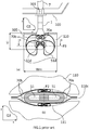
- a ladle (not shown) is filled with metal melt out of a furnace and transferred to a tundish (100) through a ladle shroud nozzle.
- the metal melt can then be cast through a pouring nozzle (1) from the tundish to a mould (110) for forming slabs, billets, beams, thin slabs, or ingots.
- Flow of metal melt out of the tundish is driven by gravity through the pouring nozzle (1) and the flow rate is controlled by a stopper (7).
- a stopper (7) is a rod movably mounted above and extending coaxially (i.e., vertically) to a tundish outlet orifice (101) in (vertical) fluid communication with the pouring nozzle.
- the end of the stopper adjacent to the tundish outlet orifice is the stopper head and has a geometry matching the geometry of said outlet orifice such that when the two are in contact with one another, the tundish outlet orifice is sealed.
- the flow rate of molten metal out of the tundish and into the mould is controlled by continuously moving up and down the stopper such as to control the space between the stopper head and the nozzle orifice.
- Slabs are continuously cast and therefore have an "infinite" length. Their cross-section can have a thickness to width aspect ratio, Tm / Wm; of the order of 1 / 4 or more. Thin slabs, are slabs of cross-section having a Tm / Wm-aspect ration greater than "conventional" slabs which can have values of 1 / 8 and greater. Slab mould cavities obviously must reflect similar aspect ratios. Even if the inlet of slab moulds may locally have a funnel-like geometry to admit a downstream portion of a slab nozzle, said downstream portion of the slab nozzle cannot have a geometry of revolution, and must have a thickness to width aspect ratio, T / W; of at least 1.5 to fit in the cavity inlet of the mould. For thin slab nozzles, the thickness to width aspect ratio, T / W; must be at least 3.
- DE19505390 describes an immersed casting tube with a long and narrow cross section, having a flattened end section with outlet openings.
- the passage cross section of the tube within its end region is divided by a distributor into a row of channels.
- Below the broad pipe walls, as far as down as the exit openings, the channels (9) are open on one side.
- WO2013004571 , WO9814292 , US2002063172 , and CN103231048 relate to a submerged entry nozzle for guiding a stream of a metal melt from a tundish into a mould with multiple (three or four) front ports having different orientations and cross-sectional size ratios.
- the present invention proposes a slab nozzle having a novel geometry which substantially enhances the service life thereof due to a much lighter and slower erosion of the outer wall of the downstream portion of the slab nozzle.
- the present invention concerns a slab nozzle for casting slabs made of metal, said slab nozzle having a geometry defined by an outer wall extending over a nozzle length, L, along a longitudinal axis, z, from an upstream end to a downstream end.
- the outer wall comprises a downstream portion extending along the longitudinal axis, z, from and including the downstream end, wherein
- the slab nozzle further comprises a central bore opening at said inlet orifice, extending therefrom along the longitudinal axis, z, and intersecting the one or more front ports each opening at the one or more outlet port orifices.
- the slab nozzle of the present invention is characterized in that, in a cut view of the slab nozzle along a transverse plane, P3, and, preferably, in cut views of the slab nozzle along any transverse plane, Pn, the outer wall of the slab nozzle is defined by an outer wall outline which comprises:
- the transverse plane, P3, is the plane normal to the longitudinal axis, z , and intersecting the one or more outlet port orifices, which distance, L3 , to the downstream end is the largest.
- a transverse plane, Pn is a plane normal to the longitudinal axis, z , and intersecting the longitudinal axis, z , at a distance, Ln, to the downstream end of not more than 60% of the nozzle length, L, preferably not more than 50% of L. All transverse planes, Pn, are parallel to the reference plane, Q3, and the transverse plane, P3 , is a specific transverse plane, Pn .
- the outer wall outline of the downstream portion is inscribed in a virtual rectangle of first and second edges parallel to the first transverse axis, x , and third and fourth edges parallel to the second transverse axis, y.
- the tight distance, dt can be at least twice, preferably at least three times shorter than a flared distance, df , of the outer wall outline to the other two diagonally opposed corners of the virtual rectangle (2 dt ⁇ df ).
- the distance of the outer wall outline to a corner is defined as the distance between said corner and a point of the outline located closest to said corner.
- the tight distance, dt is preferably not more than ten times, more preferably not more than eight times shorter than the flared distance, df.
- Another way of defining the geometry of the slab nozzle outline is by defining, on the one hand, a first and second tight areas, At, comprised between the outer wall outline and the edges of the virtual rectangle joining at the first and second diagonally opposed corners, respectively and, on the other hand, a first and second flared areas, Af .
- each of a first and second tight areas, At comprised between the outer wall outline and the edges of the virtual rectangle joining at the other two diagonally opposed corners.
- the first and second tight area, At each has an area preferably of not more than 80%, preferably not more than 67%, more preferably not more than 50% of an area of the first and second flared areas, Af, (5 At ⁇ 4 Af ).
- a stream of molten metal flowing towards the slab nozzle in a direction normal to the reference plane, Q2 will preferably flow through the gap formed between the slab nozzle and the slab mould which is on the side of the flared distance, df, and/or of the flared area, Af, and will be restricted on the side of the tight distance, dt, and/or of the tight area, At, thus creating a round-about effect, with two streams flowing in opposite directions on two opposite sides of the slab nozzle, thus avoiding any collision between the two streams within one such gap.
- the central portion ( Ax ) of the outer wall outline preferably extends over at least 33%, preferably at least 50% of the width, W , of the first and second edges of the virtual rectangle, and preferably extends not more than 85%, more preferably not more than 67% of the width, W , of the first and second edges of the virtual rectangle (33% W ⁇ Ax ⁇ 85% W )
- Protrusions can be distributed on the outer wall of the downstream portion of the slab nozzle. Protrusions allow the dissipation of the kinetic energy of a metal stream flowing through a gap. To further enhance the round-about effect, the protrusions are arranged on a first and second hindered portions of the outer wall of the downstream portion, said first and second hindered portions, corresponding to the portion of the outer wall outline in the cut along a plane, Pn , or, in particular, along the plane, P3 , which is contained in the two diagonally opposed quarters of the virtual rectangle including the tight distance, dt , or the tight area, At .
- the protrusions can have a multitude of geometries.
- the protrusions may be in the form of circles, ellipses, straight or curved lines, chevrons, arcs of circles, polygons.
- the protrusions preferably protrude out of the surface of the outer wall of the downstream portion by at least 3 mm, preferably at least 4 mm, and preferably by not more than 20 mm, more preferably, not more than 15 mm. If the protrusions are discrete protrusions, they are preferably distributed in a staggered arrangement on the outer wall of downstream portion of the slab nozzle, preferably on the first and second hindered portions thereof.
- the one or more front ports preferably flare out as they open at the corresponding outlet port orifices.
- a nozzle according to the present invention preferably comprises a first and second front ports which open at a corresponding first and second outlet port orifices.
- the first and second front ports are preferably separated from one another by a divider extending in the central bore from the downstream end along the longitudinal axis, z, and dividing the bore into the first and second front ports.
- the first and second front ports are preferably defined by a first and second front ports outlines each comprising a lateral portion remote from the divider which is symmetrical solely with respect to the central point, c , and is preferably substantially parallel to the corresponding first and second lateral portions ( Ac1, Ac2 ) of the outer wall outline.
- the present invention also concerns a metallurgic assembly for casting metal slabs, said metallurgic assembly comprising:
- a transverse plane, Pm is a plane normal to the longitudinal axis, z , and intersecting the downstream portion of the nozzle slab, over at least 40%, preferably at least 50%, more preferably at least 75% of the inserted length, Li .
- the transverse plane, P3, is a specific transverse plane, Pm, and are all parallel to the reference plane, Q3.
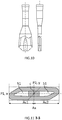
- FIGS. 4 and 5 show embodiments of a slab nozzle according to the present invention.
- the slab nozzle has a geometry defined by an outer wall extending over a nozzle length, L , along a longitudinal axis, z , from an upstream end to a downstream end.
- the upstream end of the slab nozzle comprises an inlet orifice ( 50u ) oriented parallel to said longitudinal axis, z.
- the outer wall comprises a downstream portion extending along the longitudinal axis, z, from and including the downstream end, and comprises one or more outlet port orifices ( 51d ).
- a slab nozzle generally comprises at least a first and second front ports ( 51 ) opening at a corresponding first and second outlet port orifices. The first and second front ports may be separated from one another by a divider ( 10 ) extending in the central bore from the downstream end along the longitudinal axis, z , as shown in Figure 10 .
- a slab nozzle may also comprise a front port parallel and generally coaxial with the longitudinal axis, z (not shown). In a preferred embodiment, the one or more front ports flare out as they open at the first and second outlet port orifices, as shown in Figure 10 .
- the downstream portion is defined by a width, W , measured along a first transverse axis, x , which is at least 1.5 times larger than a maximum thickness, Tx , of the downstream portion measured along a second transverse axis, y, wherein the first transverse axis, x , is normal to the longitudinal axis, z , and wherein the second transverse axis, y , is normal to both first transverse axis, x , and longitudinal axis, z .
- This W / Tx aspect ratio is required for inserting the downstream portion of the slab nozzle into the cavity of a slab mould, which is, of course, much wider than it is thick.
- the W / Tx aspect ratio is at least 3, preferably at least 4 or 5.
- the slab nozzle further comprises a central bore ( 50 ) opening at said inlet orifice (50u), extending therefrom along the longitudinal axis, z, and intersecting the one or more front ports ( 51 ) each opening at the one or more outlet port orifices.
- a metallurgic vessel 100
- the central bore of the slab nozzle is aligned and in fluid communication with an outlet ( 101 ) provided at the bottom floor of the tundish, such that the metal melt can flow out of the tundish through the outlet and through the central bore and flow out of the slab nozzle through the outlet port orifices.
- the downstream portion of the slab nozzle is inserted in a cavity (110c) of a slab mould.
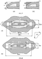
- the slab mould cavity has a width, Wm, measured along the first transverse axis, x, and a thickness, Tm, measured along the second transverse axis, y, which is constant for rectangular cavities (cf. Figure 8(b) ), and wherein Wm is at least four times larger than Tm, (Wm ⁇ 4 Tm), and even at least eight times larger than Tm, (Wm ⁇ 4 Tm) for thin slab moulds.
- a lubricant is added to the metal in the slab mould to prevent sticking, and to trap any slag particles that may be present in the metal and bring them to the top of the pool to form a floating layer of slag ( 105 ).
- the shroud is set so the hot metal exits it below the surface of the slag layer in the mold and is thus called a submerged entry nozzle (SEN).
- metal melt flowing out of the outlet ports of a slab nozzle follows a loop path along the width, Wm, of the mould cavity, at two opposite sides of the longitudinal axis, z.
- the flow path is constrained at the bottom by metal flowing at a lower rate as it solidifies in the slab mould cavity and is therefore split in two diverging flows which are deviated sideways.
- the slab mould cavity being so thin, that the flow cannot be deviated substantially into the second transverse axis, y, direction, and it must flow along the first transverse axis, x, direction on either side of the longitudinal axis, z, until it reaches the side walls at the corresponding sides of the cavity.
- the flows are deviated upwards until they are constrained by the floating layer of slag at the top of the pool.
- the metal is then deviated inwards into converging streams flowing one towards the other on either side of the slab nozzle.
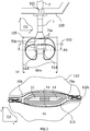
- each is split into two streams ( 70a , 70b ) flowing on either side of the outer wall of the downstream portion of the slab nozzle, that the flows see like the leading edge of a wing. If two streams ( 70a , 70b ) of molten metal flowing in opposite converging directions meet in the narrow channels ( 111 ) formed between the mould cavity wall and the outer wall on either side of the slab nozzle meet, strong turbulences would form. As discussed supra, these turbulences substantially accelerate the erosion of the slab nozzle and are detrimental to the service life thereof.
- the outer wall of a slab nozzle as seen by a stream of metal flowing towards the slab nozzle at the level of the outlet ports can be characterized by an outer wall outline of a cut view along a transverse plane, P3 , wherein the transverse plane, P3 , is the plane normal to the longitudinal axis, z , and intersecting the one or more outlet port orifices, which distance, L3 , to the downstream end is the largest.
- the outer wall outline of the corresponding cut view along the plane, P3, is therefore symmetrical at least with respect to the first transverse axis, x, and with respect to the second transverse axis, y.
- a flow of metal melt meeting the symmetrical leading edge formed by one lateral profile of such slab nozzle would therefore split into two streams (70a, 70b) of substantially identical flowrates flowing in substantially identical channels formed on either side of the slab nozzle with the mould cavity wall.
- the gist of the present invention is to prevent two streams ( 70a, 70b ) of molten metal from colliding in the narrow channels ( 111 ) formed on either side of a slab nozzle with the mould cavity wall.
- the principle is to create a round-about around the slab nozzle such that, like cars on a road, each opposite stream ( 70a, 70b ) flows through its own channel ( 111 ) on one side only of the slab nozzle.
- the stream ( 70a ) flowing from right to left is forced to flow left of the slab nozzle, through the lower channel ( 111 ) illustrated in the Figure.
- the stream ( 70b ) flowing from left to right is forced to flow left of the slab nozzle, through the upper channel ( 111 ) illustrated in the Figure.
- the two streams (70a, 70b) therefore do not meet and collide in the channels ( 111 ), but downstream of the channels, away from the outer wall of the slab nozzle, where there is more room to expand and to dissipate energy thus creating less damages to the equipment.
- the "round-about" effect is obtained by selecting the geometry of the downstream portion of the slab nozzle as follows.
- the cut view of the slab nozzle along the transverse plane, P3 , the outer wall outline of the outer wall of the slab nozzle comprises:
- the outer wall outline comprises lateral portions ( Ac1, Ac2 ) having no axial symmetry with respect to the first transverse axis, x, in order to favour the flow of a stream of molten metal along one side of the outer wall of the slab nozzle, and to hinder the flow over the opposite side with respect to the axis, x .
- the outer wall outline in the central portion ( Ax ) like in the first and second lateral portions, is symmetrical solely with respect to the central point, c .
- the central portion ( Ax ) is geometrically reduced to the second transverse axis, y , and in practice, disappears.
- the outer wall outline in the central portion ( Ax ) is symmetrical with respect to the first and/or second transverse axes, x , y , preferably with respect to both axes, x and y.
- the central portion ( Ax ) of the outer wall outline may extend over at least 33%, preferably at least 50% of the width, W , of the slab nozzle downstream portion.
- the central portion ( Ax ) preferably extends not more than 85%, more preferably not more than 67% of the lengths of the first and second edges of the virtual rectangle (33% W ⁇ Ax ⁇ 85% W).
- the first and second front ports are defined by a first and second front ports outlines each comprising a lateral portion remote from the divider which is symmetrical solely with respect to the central point, c , and is preferably substantially parallel to the corresponding first and second lateral portions ( Ac1, Ac2 ) of the outer wall outline.
- the same asymmetry be applied to the geometry of the front ports as to the outer wall, such that the nozzle wall has a substantially constant thickness. This way there is no risk of having a weak spot wherein the wall is too thin, or of wasting refractory material by unnecessarily locally increasing the thickness of the outer wall.
- the outer wall of the slab nozzle is defined by an outer wall outline which comprises a central portion and a first and second lateral portions as defined supra with respect to the transverse plane, P3 .
- a transverse plane, Pn is a plane normal to the longitudinal axis, z , and intersecting the longitudinal axis, z, at a distance, Ln , to the downstream end of not more than 60% of the nozzle length, L, preferably not more than 50% of L , more preferably not more than 40% of L.
- the distance, Ln is at least 1% of L , more preferably at least 2% of L, most preferably at least 5% of L.
- the transverse plane, P3, is one particular plane, Pn.
- the outer wall outline of the downstream portion is inscribed in a virtual rectangle of first and second edges parallel to the first transverse axis, x, and third and fourth edges parallel to the second transverse axis, y.
- the "round-about" effect is obtained by ensuring that a tight distance, dt, of the outer wall outline to first and second diagonally opposed corners of the four corners of the virtual rectangle is at least 1.5 times, preferably at least twice (i.e., 2 dt :5 df ), more preferably at least three times (i.e., 3 dt ⁇ df ) shorter than the flared distance, df, of the outer wall outline to the other two diagonally opposed corners of the virtual rectangle, wherein a distance of the outer wall outline to a corner is defined as the distance between said corner and a point of the outline located closest to said corner.
- the channel (or "strait" using nautical terms) formed between the outer wall of the slab nozzle and the mould cavity wall is broader on the side of flared distance, df, defining a "flowing side” of the slab nozzle forming the broad side of a funnel where the molten metal can flow more easily than on the side of tight distance, dt, defining a "hindered side” of the slab nozzle and forming the tight side of the funnel, where flow is hindered.
- each of a first and second tight areas, At comprised between the outer wall outline and the edges of the virtual rectangle joining at the first and second diagonally opposed corners, respectively has an area of not more than 80% (i.e., 5 At ⁇ 4 Af ), preferably not more than 67% (i.e., 3 At ⁇ 2 Af ), more preferably not more than 50% (i.e., 2 At ⁇ Af ) of an area of a first and second flared areas, Af, comprised between the outer wall outline and the edges of the virtual rectangle joining at the other two diagonally opposed corners.
- the flow of a molten metal stream is favoured on the side of the slab nozzle wherein the area, Af, defines the broad side of a funnel, compared with the side of area, At, defining the tight side of a funnel, where flow is hindered.
- the round-about effect is obtained by forcing a stream of molten metal flowing towards a lateral profile of the slab nozzle to be deviated preferentially to a flowing side of the slab nozzle, rather than to the opposite, hindered side of the slab nozzle.
- This is achieved by facilitating flow through the flowing side of the slab nozzle by forming a broad funnel entrance at the flowing side and forming a narrow side of the funnel at the hindered side.
- molten metal cannot be prevented from flowing the wrong way with a traffic sign.
- a stream of molten metal can further be hindered from flowing down the wrong way of the hindered side of the slab nozzle by providing a number of protrusions jutting out of the outer wall of the downstream portion of the slab.
- Said protrusions are preferably distributed over an area of the outer wall comprised within the two diagonally opposed quarters of the virtual rectangle (i.e., intersecting at the central point, c, only) containing the hindered sides of the slab nozzle outer wall outline, which can be characterized by the tight distance, dt, or by the tight area, At.
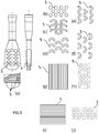
- the protrusions ( 5 ) may have different geometries, including circles and ellipses (cf. Figure 9(b) ), straight or curved lines, which can be continuous or discontinuous (cf. Figure 9(h) &(g)), chevrons (cf. Figure 9(d) &(e)), arcs of circles (cf. Figure 9(d) &(f)), polygons (not shown), and the like.
- the protrusions preferably protrude out of the surface of the outer wall of the downstream portion by at least 3 mm, preferably at least 4 mm, and preferably by not more than 20 mm, more preferably, not more than 15 mm.
- the protrusions can be continuous lines, as shown in Figure 9(g) to (j) , or discrete protrusions, as shown in Figure 9(a)-(f) .
- Discrete protrusions are preferably distributed in a staggered arrangement on the first and second hindered portions of the outer wall of the downstream portion.
- Protrusions as illustrated in Figure 9(e) &(f) comprising a concave side facing the stream to be hindered from flowing are particularly effective for promoting the round-about effect sought in the present invention.
- the slab nozzle of the present invention is used in a metallurgic assembly for casting metal slabs as illustrated in Figure 2 .
- Said metallurgic assembly comprises:
- the cavity of the slab mould is defined by cavity walls extending along the longitudinal axis, z.
- the cavity wall is defined by a cavity wall outline illustrated in Figure 8 .
- the cavity wall oultine comprises:
- Tmx Tmc, defining a rectangular cavity wall outline, as shown in Figure 8(b) .
- the mould cavity may include a funnel shaped portion allowing the insertion of the downstream portion of the slab nozzle.
- This embodiment is illustrated in Figure 8(a) , wherein the thickness of the mould cavity wall outline in the central portion gradually increases compared with the lateral portions until reaching the maximum cavity thickness value, Tmx > Tmc.
- This funnel shaped central portion of the cavity wall ends in the z -direction below the downstream end of the slab nozzle, at which point, the mould cavity has a rectangular cross-section.
- the cross-sections normal to the longitudinal axis, z, of the funnel shaped central portion preferably have a cavity wall outline which is symmetrical with respect to both first and second transverse axes, x , y .
- the width, Wmx , of the cavity wall central portion measured along the x -direction must be larger than the width, W, of the slab nozzle.
- the maximum cavity thickness value, Tmx, measured along the y -direction must be larger than the maximum thickness, Tx, of the slab nozzle.
- the thickness ratio, Tmx / Tx , of the slab mould to the slab nozzle is comprised between 1.2 and 2.7, preferably between 1.5 and 2.1.
- channels or gaps are formed between the slab nozzle outer wall and the cavity wall on either side of the first transverse axis, x.
- the streams of molten metal flow substantially parallel to the first transverse axis, x , in opposite converging directions towards the second transverse axis, y .
- the round-about effect illustrated in Figure 2(b) wherein each stream preferentially flows along its own channel at one side of the first longitudinal axis, x , is obtained by controlling the respective widths, Gt and Gf , of the channels entries at the hindered and flowing sides of the slab nozzle, respectively.
- the channels or gaps can be defined as explained below.
- a first tight gap between the cavity wall outline and the first lateral portions ( Ac1 ) of the outer wall outline having a first tight gap width, Gt1 , measured at a first side of the first transverse axis, x, along a segment, m, parallel to the second transverse axis, y, and passing by an intersection point between the first lateral portions ( Ac1 ) of the outer wall outline and the first transverse axis, x .
- the first tight gap width, Gt1 is not more than half, preferably, not more than a third of a first flared gap width, Gf1 , of a first flared gap between the cavity wall outline and the first lateral portions ( Ac1 ) of the outer wall outline measured at a second side of the first transverse axis, x, along the segment, m, (2 Gt1 ⁇ Gf1 ),
- the second tight gap has a second tight gap width, Gt2 , measured at the second side of the first transverse axis, x, along a segment, n, parallel to the second transverse axis, y, and passing by an intersection point between the second lateral portions ( Ac2 ) of the outer wall outline and the first transverse axis, x.
- the second tight gap width, Gt2 is not more than half, preferably, not more than a third of a second flared gap width, Gf2 , of a second flared gap between the cavity wall outline and the second lateral portions ( Ac2 ) of the outer wall outline measured at the first side of the first transverse axis, x, along the segment, n, (2 Gt2 ⁇ Gf2 ),
- Tmx 1 56 to 251 mm
- a slab nozzle 130 mm.
- the tight gap width, Gt1 , Gt2 can be comprised between 13 and 91 mm, in general, about 40 mm.
- the geometries of the metallurgic assembly defined supra with respect to a cut along the transverse plane, P3, preferably also apply to any cut along any transverse plane, Pm, defined as a plane normal to the longitudinal axis, z, and intersecting the downstream portion of the nozzle slab, over at least 40%, preferably at least 50%, more preferably at least 75% of the inserted length, Li .
- the transverse planes, Pm preferably intersect the downstream portion of the nozzle slab above the downstream end of the slab nozzle, preferably at least 1%, more preferably at least 5% of the inserted length, Li , above the downstream end.
- the following magnitudes defined with respect to the cut along plane, P3 also apply for cuts along a plane, Pm :
- the impact or impinging area between the two opposite streams, normally located in the narrow channels between mould and slab nozzle is shifted away from the slab nozzle, and the turbulences thus created have substantially less impact on the erosion of the slab nozzle outer wall.
- the service life of the slab nozzle can thus be substantially prolonged.
- a slab nozzle according to the present invention can be used in any existing metallurgic installation and yield the foregoing advantages without any change in the rest of the installation. The round-about effect permits a substantial reduction of the erosion rate of the slab nozzle outer wall.
Landscapes
- Engineering & Computer Science (AREA)
- Mechanical Engineering (AREA)
- Continuous Casting (AREA)
- Casting Support Devices, Ladles, And Melt Control Thereby (AREA)
- Furnace Charging Or Discharging (AREA)
- Revetment (AREA)
Priority Applications (1)
| Application Number | Priority Date | Filing Date | Title |
|---|---|---|---|
| PL18729575T PL3624964T3 (pl) | 2017-05-15 | 2018-05-14 | Asymetryczna dysza płaska i zawierający ją zespół metalurgiczny do odlewania metalu |
Applications Claiming Priority (2)
| Application Number | Priority Date | Filing Date | Title |
|---|---|---|---|
| EP17171047 | 2017-05-15 | ||
| PCT/EP2018/062420 WO2018210772A1 (en) | 2017-05-15 | 2018-05-14 | Asymetric slab nozzle and metallurgical assembly for casting metal including it |
Publications (2)
| Publication Number | Publication Date |
|---|---|
| EP3624964A1 EP3624964A1 (en) | 2020-03-25 |
| EP3624964B1 true EP3624964B1 (en) | 2021-02-24 |
Family
ID=58709361
Family Applications (1)
| Application Number | Title | Priority Date | Filing Date |
|---|---|---|---|
| EP18729575.3A Active EP3624964B1 (en) | 2017-05-15 | 2018-05-14 | Asymetric slab nozzle and metallurgical assembly for casting metal including it |
Country Status (12)
| Country | Link |
|---|---|
| US (1) | US11103921B2 (pl) |
| EP (1) | EP3624964B1 (pl) |
| JP (1) | JP7169300B2 (pl) |
| KR (1) | KR102535078B1 (pl) |
| CN (2) | CN108856693B (pl) |
| BR (1) | BR112019022234B1 (pl) |
| MX (1) | MX395024B (pl) |
| MY (1) | MY200287A (pl) |
| PL (1) | PL3624964T3 (pl) |
| RU (1) | RU2756838C2 (pl) |
| WO (1) | WO2018210772A1 (pl) |
| ZA (1) | ZA201906623B (pl) |
Family Cites Families (22)
| Publication number | Priority date | Publication date | Assignee | Title |
|---|---|---|---|---|
| SU599915A1 (ru) * | 1976-05-04 | 1978-04-11 | Череповецкий Ордена Ленина Металлургический Завод Им.50-Летия Ссср | Разливочный стакан |
| JPS62227558A (ja) * | 1986-03-31 | 1987-10-06 | Daido Steel Co Ltd | 連続鋳造方法 |
| JPS62270261A (ja) * | 1986-05-16 | 1987-11-24 | Daido Steel Co Ltd | 連続鋳造装置の浸漬ノズル |
| JPS63235050A (ja) * | 1987-03-25 | 1988-09-30 | Nkk Corp | 浸漬ノズル |
| DE4142447C3 (de) * | 1991-06-21 | 1999-09-09 | Mannesmann Ag | Tauchgießrohr - Dünnbramme |
| US5785880A (en) * | 1994-03-31 | 1998-07-28 | Vesuvius Usa | Submerged entry nozzle |
| DE4436990C1 (de) * | 1994-10-07 | 1995-12-07 | Mannesmann Ag | Tauchgießrohr |
| DE19505390C2 (de) * | 1995-02-17 | 2003-10-30 | Sms Demag Ag | Tauchgießrohr |
| IT1284035B1 (it) | 1996-06-19 | 1998-05-08 | Giovanni Arvedi | Tuffante per la colata continua di bramme sottili |
| UA51734C2 (uk) | 1996-10-03 | 2002-12-16 | Візувіус Крусібл Компані | Занурений стакан для пропускання рідкого металу і спосіб пропускання рідкого металу через нього |
| IT1290931B1 (it) * | 1997-02-14 | 1998-12-14 | Acciai Speciali Terni Spa | Alimentatore di metallo fuso per lingottiera di macchine di colata continua. |
| JP2001286993A (ja) * | 2000-03-31 | 2001-10-16 | Kawasaki Steel Corp | 連続鋳造方法 |
| US6467704B2 (en) | 2000-11-30 | 2002-10-22 | Foseco International Limited | Nozzle for guiding molten metal |
| RU2188099C1 (ru) * | 2001-12-24 | 2002-08-27 | Коротков Борис Алексеевич | Огнеупорный стакан |
| US20060243760A1 (en) * | 2005-04-27 | 2006-11-02 | Mcintosh James L | Submerged entry nozzle |
| CN201026526Y (zh) * | 2007-04-26 | 2008-02-27 | 鞍山市东方巨业高级陶瓷有限公司 | 薄板坯连铸用高钢水通量浸入式水口 |
| CN201442094U (zh) * | 2008-11-28 | 2010-04-28 | 中钢集团洛阳耐火材料研究院有限公司 | 一种内壁具有复合层的薄板坯连铸用浸入式水口 |
| RU2466825C2 (ru) * | 2010-03-30 | 2012-11-20 | Акети Керамикс Ко., Лтд. | Разливочный стакан для непрерывного литья |
| CN103608137B (zh) | 2011-07-06 | 2016-09-28 | 里弗雷克特里知识产权两合公司 | 用于引导金属熔体的喷嘴 |
| CN103231048B (zh) | 2013-05-17 | 2015-08-12 | 辽宁科技大学 | 高拉速ftsc薄板坯连铸结晶器用四孔式浸入式水口 |
| MX373918B (es) * | 2014-06-11 | 2020-04-30 | Arvedi Steel Eng S P A | Boquilla de placa delgada para la distribución de altas tasas de flujo masivo. |
| JP2016131983A (ja) * | 2015-01-16 | 2016-07-25 | 品川リフラクトリーズ株式会社 | 溶鋼の連続鋳造方法 |
-
2018
- 2018-05-14 PL PL18729575T patent/PL3624964T3/pl unknown
- 2018-05-14 WO PCT/EP2018/062420 patent/WO2018210772A1/en not_active Ceased
- 2018-05-14 CN CN201810458320.XA patent/CN108856693B/zh active Active
- 2018-05-14 BR BR112019022234-0A patent/BR112019022234B1/pt active IP Right Grant
- 2018-05-14 KR KR1020197032666A patent/KR102535078B1/ko active Active
- 2018-05-14 CN CN201820712954.9U patent/CN208976824U/zh not_active Withdrawn - After Issue
- 2018-05-14 JP JP2019563228A patent/JP7169300B2/ja not_active Expired - Fee Related
- 2018-05-14 EP EP18729575.3A patent/EP3624964B1/en active Active
- 2018-05-14 RU RU2019130483A patent/RU2756838C2/ru active
- 2018-05-14 MX MX2019013593A patent/MX395024B/es unknown
- 2018-05-14 US US16/609,010 patent/US11103921B2/en active Active
- 2018-05-14 MY MYPI2019005940A patent/MY200287A/en unknown
-
2019
- 2019-10-08 ZA ZA2019/06623A patent/ZA201906623B/en unknown
Non-Patent Citations (1)
| Title |
|---|
| None * |
Also Published As
| Publication number | Publication date |
|---|---|
| RU2756838C2 (ru) | 2021-10-06 |
| CA3058627A1 (en) | 2018-11-22 |
| JP2020519450A (ja) | 2020-07-02 |
| RU2019130483A3 (pl) | 2021-08-10 |
| MX395024B (es) | 2025-03-24 |
| MX2019013593A (es) | 2020-01-13 |
| ZA201906623B (en) | 2021-04-28 |
| RU2019130483A (ru) | 2021-06-16 |
| BR112019022234B1 (pt) | 2023-03-07 |
| BR112019022234A2 (pt) | 2020-05-19 |
| WO2018210772A1 (en) | 2018-11-22 |
| KR20200007803A (ko) | 2020-01-22 |
| JP7169300B2 (ja) | 2022-11-10 |
| EP3624964A1 (en) | 2020-03-25 |
| MY200287A (en) | 2023-12-19 |
| US20200238373A1 (en) | 2020-07-30 |
| CN108856693A (zh) | 2018-11-23 |
| US11103921B2 (en) | 2021-08-31 |
| CN108856693B (zh) | 2022-04-29 |
| KR102535078B1 (ko) | 2023-05-19 |
| CN208976824U (zh) | 2019-06-14 |
| PL3624964T3 (pl) | 2021-08-30 |
Similar Documents
| Publication | Publication Date | Title |
|---|---|---|
| US20080210401A1 (en) | Submerged entry nozzle with installable parts | |
| CN1072538C (zh) | 薄板坯连铸用浸入式水口 | |
| JPH08168856A (ja) | 連続鋳造用排出ノズル | |
| EP3154726B1 (en) | Thin slab nozzle for distributing high mass flow rates | |
| US10065237B2 (en) | Nozzle and casting installation | |
| JP3050101B2 (ja) | 連続鋳造用注入装置 | |
| JPH0852547A (ja) | 浸漬鋳造管 | |
| US11103921B2 (en) | Asymmetric slab nozzle and metallurgical assembly for casting metal including it | |
| CA3058627C (en) | Asymetric slab nozzle and metallurgical assembly for casting metal including it | |
| CN108495727B (zh) | 带有导流块的连铸水口 | |
| KR20050021278A (ko) | 연속주조용 침지노즐 |
Legal Events
| Date | Code | Title | Description |
|---|---|---|---|
| STAA | Information on the status of an ep patent application or granted ep patent |
Free format text: STATUS: UNKNOWN |
|
| STAA | Information on the status of an ep patent application or granted ep patent |
Free format text: STATUS: THE INTERNATIONAL PUBLICATION HAS BEEN MADE |
|
| PUAI | Public reference made under article 153(3) epc to a published international application that has entered the european phase |
Free format text: ORIGINAL CODE: 0009012 |
|
| STAA | Information on the status of an ep patent application or granted ep patent |
Free format text: STATUS: REQUEST FOR EXAMINATION WAS MADE |
|
| 17P | Request for examination filed |
Effective date: 20191216 |
|
| AK | Designated contracting states |
Kind code of ref document: A1 Designated state(s): AL AT BE BG CH CY CZ DE DK EE ES FI FR GB GR HR HU IE IS IT LI LT LU LV MC MK MT NL NO PL PT RO RS SE SI SK SM TR |
|
| AX | Request for extension of the european patent |
Extension state: BA ME |
|
| DAV | Request for validation of the european patent (deleted) | ||
| DAX | Request for extension of the european patent (deleted) | ||
| GRAP | Despatch of communication of intention to grant a patent |
Free format text: ORIGINAL CODE: EPIDOSNIGR1 |
|
| STAA | Information on the status of an ep patent application or granted ep patent |
Free format text: STATUS: GRANT OF PATENT IS INTENDED |
|
| INTG | Intention to grant announced |
Effective date: 20200918 |
|
| GRAS | Grant fee paid |
Free format text: ORIGINAL CODE: EPIDOSNIGR3 |
|
| GRAA | (expected) grant |
Free format text: ORIGINAL CODE: 0009210 |
|
| STAA | Information on the status of an ep patent application or granted ep patent |
Free format text: STATUS: THE PATENT HAS BEEN GRANTED |
|
| AK | Designated contracting states |
Kind code of ref document: B1 Designated state(s): AL AT BE BG CH CY CZ DE DK EE ES FI FR GB GR HR HU IE IS IT LI LT LU LV MC MK MT NL NO PL PT RO RS SE SI SK SM TR |
|
| REG | Reference to a national code |
Ref country code: CH Ref legal event code: EP |
|
| REG | Reference to a national code |
Ref country code: AT Ref legal event code: REF Ref document number: 1363817 Country of ref document: AT Kind code of ref document: T Effective date: 20210315 |
|
| REG | Reference to a national code |
Ref country code: IE Ref legal event code: FG4D |
|
| REG | Reference to a national code |
Ref country code: DE Ref legal event code: R096 Ref document number: 602018013096 Country of ref document: DE |
|
| REG | Reference to a national code |
Ref country code: FI Ref legal event code: FGE |
|
| REG | Reference to a national code |
Ref country code: SE Ref legal event code: TRGR |
|
| REG | Reference to a national code |
Ref country code: NL Ref legal event code: FP |
|
| REG | Reference to a national code |
Ref country code: LT Ref legal event code: MG9D |
|
| PG25 | Lapsed in a contracting state [announced via postgrant information from national office to epo] |
Ref country code: NO Free format text: LAPSE BECAUSE OF FAILURE TO SUBMIT A TRANSLATION OF THE DESCRIPTION OR TO PAY THE FEE WITHIN THE PRESCRIBED TIME-LIMIT Effective date: 20210524 Ref country code: PT Free format text: LAPSE BECAUSE OF FAILURE TO SUBMIT A TRANSLATION OF THE DESCRIPTION OR TO PAY THE FEE WITHIN THE PRESCRIBED TIME-LIMIT Effective date: 20210624 Ref country code: LT Free format text: LAPSE BECAUSE OF FAILURE TO SUBMIT A TRANSLATION OF THE DESCRIPTION OR TO PAY THE FEE WITHIN THE PRESCRIBED TIME-LIMIT Effective date: 20210224 Ref country code: HR Free format text: LAPSE BECAUSE OF FAILURE TO SUBMIT A TRANSLATION OF THE DESCRIPTION OR TO PAY THE FEE WITHIN THE PRESCRIBED TIME-LIMIT Effective date: 20210224 Ref country code: GR Free format text: LAPSE BECAUSE OF FAILURE TO SUBMIT A TRANSLATION OF THE DESCRIPTION OR TO PAY THE FEE WITHIN THE PRESCRIBED TIME-LIMIT Effective date: 20210525 Ref country code: BG Free format text: LAPSE BECAUSE OF FAILURE TO SUBMIT A TRANSLATION OF THE DESCRIPTION OR TO PAY THE FEE WITHIN THE PRESCRIBED TIME-LIMIT Effective date: 20210524 |
|
| PG25 | Lapsed in a contracting state [announced via postgrant information from national office to epo] |
Ref country code: LV Free format text: LAPSE BECAUSE OF FAILURE TO SUBMIT A TRANSLATION OF THE DESCRIPTION OR TO PAY THE FEE WITHIN THE PRESCRIBED TIME-LIMIT Effective date: 20210224 Ref country code: RS Free format text: LAPSE BECAUSE OF FAILURE TO SUBMIT A TRANSLATION OF THE DESCRIPTION OR TO PAY THE FEE WITHIN THE PRESCRIBED TIME-LIMIT Effective date: 20210224 |
|
| PGFP | Annual fee paid to national office [announced via postgrant information from national office to epo] |
Ref country code: ES Payment date: 20210601 Year of fee payment: 4 |
|
| PG25 | Lapsed in a contracting state [announced via postgrant information from national office to epo] |
Ref country code: IS Free format text: LAPSE BECAUSE OF FAILURE TO SUBMIT A TRANSLATION OF THE DESCRIPTION OR TO PAY THE FEE WITHIN THE PRESCRIBED TIME-LIMIT Effective date: 20210624 |
|
| REG | Reference to a national code |
Ref country code: AT Ref legal event code: UEP Ref document number: 1363817 Country of ref document: AT Kind code of ref document: T Effective date: 20210224 |
|
| PG25 | Lapsed in a contracting state [announced via postgrant information from national office to epo] |
Ref country code: CZ Free format text: LAPSE BECAUSE OF FAILURE TO SUBMIT A TRANSLATION OF THE DESCRIPTION OR TO PAY THE FEE WITHIN THE PRESCRIBED TIME-LIMIT Effective date: 20210224 Ref country code: EE Free format text: LAPSE BECAUSE OF FAILURE TO SUBMIT A TRANSLATION OF THE DESCRIPTION OR TO PAY THE FEE WITHIN THE PRESCRIBED TIME-LIMIT Effective date: 20210224 Ref country code: SM Free format text: LAPSE BECAUSE OF FAILURE TO SUBMIT A TRANSLATION OF THE DESCRIPTION OR TO PAY THE FEE WITHIN THE PRESCRIBED TIME-LIMIT Effective date: 20210224 |
|
| REG | Reference to a national code |
Ref country code: DE Ref legal event code: R097 Ref document number: 602018013096 Country of ref document: DE |
|
| PG25 | Lapsed in a contracting state [announced via postgrant information from national office to epo] |
Ref country code: RO Free format text: LAPSE BECAUSE OF FAILURE TO SUBMIT A TRANSLATION OF THE DESCRIPTION OR TO PAY THE FEE WITHIN THE PRESCRIBED TIME-LIMIT Effective date: 20210224 Ref country code: SK Free format text: LAPSE BECAUSE OF FAILURE TO SUBMIT A TRANSLATION OF THE DESCRIPTION OR TO PAY THE FEE WITHIN THE PRESCRIBED TIME-LIMIT Effective date: 20210224 Ref country code: DK Free format text: LAPSE BECAUSE OF FAILURE TO SUBMIT A TRANSLATION OF THE DESCRIPTION OR TO PAY THE FEE WITHIN THE PRESCRIBED TIME-LIMIT Effective date: 20210224 |
|
| REG | Reference to a national code |
Ref country code: CH Ref legal event code: PL |
|
| PLBE | No opposition filed within time limit |
Free format text: ORIGINAL CODE: 0009261 |
|
| STAA | Information on the status of an ep patent application or granted ep patent |
Free format text: STATUS: NO OPPOSITION FILED WITHIN TIME LIMIT |
|
| PG25 | Lapsed in a contracting state [announced via postgrant information from national office to epo] |
Ref country code: AL Free format text: LAPSE BECAUSE OF FAILURE TO SUBMIT A TRANSLATION OF THE DESCRIPTION OR TO PAY THE FEE WITHIN THE PRESCRIBED TIME-LIMIT Effective date: 20210224 Ref country code: CH Free format text: LAPSE BECAUSE OF NON-PAYMENT OF DUE FEES Effective date: 20210531 Ref country code: LU Free format text: LAPSE BECAUSE OF NON-PAYMENT OF DUE FEES Effective date: 20210514 Ref country code: LI Free format text: LAPSE BECAUSE OF NON-PAYMENT OF DUE FEES Effective date: 20210531 Ref country code: MC Free format text: LAPSE BECAUSE OF FAILURE TO SUBMIT A TRANSLATION OF THE DESCRIPTION OR TO PAY THE FEE WITHIN THE PRESCRIBED TIME-LIMIT Effective date: 20210224 Ref country code: ES Free format text: LAPSE BECAUSE OF FAILURE TO SUBMIT A TRANSLATION OF THE DESCRIPTION OR TO PAY THE FEE WITHIN THE PRESCRIBED TIME-LIMIT Effective date: 20210224 |
|
| 26N | No opposition filed |
Effective date: 20211125 |
|
| PG25 | Lapsed in a contracting state [announced via postgrant information from national office to epo] |
Ref country code: SI Free format text: LAPSE BECAUSE OF FAILURE TO SUBMIT A TRANSLATION OF THE DESCRIPTION OR TO PAY THE FEE WITHIN THE PRESCRIBED TIME-LIMIT Effective date: 20210224 |
|
| PG25 | Lapsed in a contracting state [announced via postgrant information from national office to epo] |
Ref country code: IE Free format text: LAPSE BECAUSE OF NON-PAYMENT OF DUE FEES Effective date: 20210514 |
|
| PG25 | Lapsed in a contracting state [announced via postgrant information from national office to epo] |
Ref country code: IS Free format text: LAPSE BECAUSE OF FAILURE TO SUBMIT A TRANSLATION OF THE DESCRIPTION OR TO PAY THE FEE WITHIN THE PRESCRIBED TIME-LIMIT Effective date: 20210624 |
|
| P01 | Opt-out of the competence of the unified patent court (upc) registered |
Effective date: 20230524 |
|
| PG25 | Lapsed in a contracting state [announced via postgrant information from national office to epo] |
Ref country code: CY Free format text: LAPSE BECAUSE OF FAILURE TO SUBMIT A TRANSLATION OF THE DESCRIPTION OR TO PAY THE FEE WITHIN THE PRESCRIBED TIME-LIMIT Effective date: 20210224 |
|
| PG25 | Lapsed in a contracting state [announced via postgrant information from national office to epo] |
Ref country code: HU Free format text: LAPSE BECAUSE OF FAILURE TO SUBMIT A TRANSLATION OF THE DESCRIPTION OR TO PAY THE FEE WITHIN THE PRESCRIBED TIME-LIMIT; INVALID AB INITIO Effective date: 20180514 |
|
| PG25 | Lapsed in a contracting state [announced via postgrant information from national office to epo] |
Ref country code: MK Free format text: LAPSE BECAUSE OF FAILURE TO SUBMIT A TRANSLATION OF THE DESCRIPTION OR TO PAY THE FEE WITHIN THE PRESCRIBED TIME-LIMIT Effective date: 20210224 |
|
| PG25 | Lapsed in a contracting state [announced via postgrant information from national office to epo] |
Ref country code: TR Free format text: LAPSE BECAUSE OF FAILURE TO SUBMIT A TRANSLATION OF THE DESCRIPTION OR TO PAY THE FEE WITHIN THE PRESCRIBED TIME-LIMIT Effective date: 20210224 |
|
| PG25 | Lapsed in a contracting state [announced via postgrant information from national office to epo] |
Ref country code: MT Free format text: LAPSE BECAUSE OF FAILURE TO SUBMIT A TRANSLATION OF THE DESCRIPTION OR TO PAY THE FEE WITHIN THE PRESCRIBED TIME-LIMIT Effective date: 20210224 |
|
| PGFP | Annual fee paid to national office [announced via postgrant information from national office to epo] |
Ref country code: FI Payment date: 20250526 Year of fee payment: 8 |
|
| PGFP | Annual fee paid to national office [announced via postgrant information from national office to epo] |
Ref country code: GB Payment date: 20250527 Year of fee payment: 8 |
|
| PGFP | Annual fee paid to national office [announced via postgrant information from national office to epo] |
Ref country code: FR Payment date: 20250526 Year of fee payment: 8 |
|
| REG | Reference to a national code |
Ref country code: NL Ref legal event code: PD Owner name: VESUVIUS GROUP, S.A.; BE Free format text: DETAILS ASSIGNMENT: CHANGE OF OWNER(S), ASSIGNMENT; FORMER OWNER NAME: VESUVIUS USA CORPORATION Effective date: 20250905 |
|
| REG | Reference to a national code |
Ref country code: DE Ref legal event code: R081 Ref document number: 602018013096 Country of ref document: DE Owner name: VESUVIUS GROUP S.A., BE Free format text: FORMER OWNER: VESUVIUS USA CORP., CHAMPAIGN, IL, US |
|
| REG | Reference to a national code |
Ref country code: AT Ref legal event code: PC Ref document number: 1363817 Country of ref document: AT Kind code of ref document: T Owner name: VESUVIUS GROUP, S.A., BE Effective date: 20251103 |
|
| PGFP | Annual fee paid to national office [announced via postgrant information from national office to epo] |
Ref country code: NL Payment date: 20260526 Year of fee payment: 9 |
|
| PGFP | Annual fee paid to national office [announced via postgrant information from national office to epo] |
Ref country code: PL Payment date: 20260428 Year of fee payment: 9 |
|
| PGFP | Annual fee paid to national office [announced via postgrant information from national office to epo] |
Ref country code: IT Payment date: 20260520 Year of fee payment: 9 |
|
| PGFP | Annual fee paid to national office [announced via postgrant information from national office to epo] |
Ref country code: DE Payment date: 20260528 Year of fee payment: 9 |
|
| PGFP | Annual fee paid to national office [announced via postgrant information from national office to epo] |
Ref country code: SE Payment date: 20260527 Year of fee payment: 9 Ref country code: AT Payment date: 20260528 Year of fee payment: 9 |
|
| PGFP | Annual fee paid to national office [announced via postgrant information from national office to epo] |
Ref country code: BE Payment date: 20260527 Year of fee payment: 9 |