EP3623327A1 - Verfahren zum frankieren von auf einer förderstrecke einer frankiermaschine zugeführten versandstücken, und dazugehörige einrichtung - Google Patents
Verfahren zum frankieren von auf einer förderstrecke einer frankiermaschine zugeführten versandstücken, und dazugehörige einrichtung Download PDFInfo
- Publication number
- EP3623327A1 EP3623327A1 EP18405019.3A EP18405019A EP3623327A1 EP 3623327 A1 EP3623327 A1 EP 3623327A1 EP 18405019 A EP18405019 A EP 18405019A EP 3623327 A1 EP3623327 A1 EP 3623327A1
- Authority
- EP
- European Patent Office
- Prior art keywords
- conveying
- franking machine
- switch
- packages
- franking
- Prior art date
- Legal status (The legal status is an assumption and is not a legal conclusion. Google has not performed a legal analysis and makes no representation as to the accuracy of the status listed.)
- Granted
Links
Images


Classifications
-
- B—PERFORMING OPERATIONS; TRANSPORTING
- B65—CONVEYING; PACKING; STORING; HANDLING THIN OR FILAMENTARY MATERIAL
- B65H—HANDLING THIN OR FILAMENTARY MATERIAL, e.g. SHEETS, WEBS, CABLES
- B65H31/00—Pile receivers
- B65H31/02—Pile receivers with stationary end support against which pile accumulates
-
- B—PERFORMING OPERATIONS; TRANSPORTING
- B65—CONVEYING; PACKING; STORING; HANDLING THIN OR FILAMENTARY MATERIAL
- B65H—HANDLING THIN OR FILAMENTARY MATERIAL, e.g. SHEETS, WEBS, CABLES
- B65H29/00—Delivering or advancing articles from machines; Advancing articles to or into piles
- B65H29/58—Article switches or diverters
-
- B—PERFORMING OPERATIONS; TRANSPORTING
- B41—PRINTING; LINING MACHINES; TYPEWRITERS; STAMPS
- B41L—APPARATUS OR DEVICES FOR MANIFOLDING, DUPLICATING OR PRINTING FOR OFFICE OR OTHER COMMERCIAL PURPOSES; ADDRESSING MACHINES OR LIKE SERIES-PRINTING MACHINES
- B41L45/00—Kinds or types of addressing machines or of like series-printing machines
- B41L45/02—Kinds or types of addressing machines or of like series-printing machines using printing plates
- B41L45/06—Kinds or types of addressing machines or of like series-printing machines using printing plates for addressing combined with other operations, e.g. franking, collating documents
-
- B—PERFORMING OPERATIONS; TRANSPORTING
- B41—PRINTING; LINING MACHINES; TYPEWRITERS; STAMPS
- B41L—APPARATUS OR DEVICES FOR MANIFOLDING, DUPLICATING OR PRINTING FOR OFFICE OR OTHER COMMERCIAL PURPOSES; ADDRESSING MACHINES OR LIKE SERIES-PRINTING MACHINES
- B41L47/00—Details of addressographs or like series-printing machines
- B41L47/24—Mechanisms for conveying copy material through addressographs or like series-printing machines
-
- B—PERFORMING OPERATIONS; TRANSPORTING
- B65—CONVEYING; PACKING; STORING; HANDLING THIN OR FILAMENTARY MATERIAL
- B65H—HANDLING THIN OR FILAMENTARY MATERIAL, e.g. SHEETS, WEBS, CABLES
- B65H29/00—Delivering or advancing articles from machines; Advancing articles to or into piles
- B65H29/12—Delivering or advancing articles from machines; Advancing articles to or into piles by means of the nip between two, or between two sets of, moving tapes or bands or rollers
- B65H29/14—Delivering or advancing articles from machines; Advancing articles to or into piles by means of the nip between two, or between two sets of, moving tapes or bands or rollers and introducing into a pile
-
- B—PERFORMING OPERATIONS; TRANSPORTING
- B65—CONVEYING; PACKING; STORING; HANDLING THIN OR FILAMENTARY MATERIAL
- B65H—HANDLING THIN OR FILAMENTARY MATERIAL, e.g. SHEETS, WEBS, CABLES
- B65H29/00—Delivering or advancing articles from machines; Advancing articles to or into piles
- B65H29/52—Stationary guides or smoothers
-
- B—PERFORMING OPERATIONS; TRANSPORTING
- B65—CONVEYING; PACKING; STORING; HANDLING THIN OR FILAMENTARY MATERIAL
- B65H—HANDLING THIN OR FILAMENTARY MATERIAL, e.g. SHEETS, WEBS, CABLES
- B65H3/00—Separating articles from piles
- B65H3/02—Separating articles from piles using friction forces between articles and separator
- B65H3/06—Rollers or like rotary separators
- B65H3/063—Rollers or like rotary separators separating from the bottom of pile
-
- B—PERFORMING OPERATIONS; TRANSPORTING
- B65—CONVEYING; PACKING; STORING; HANDLING THIN OR FILAMENTARY MATERIAL
- B65H—HANDLING THIN OR FILAMENTARY MATERIAL, e.g. SHEETS, WEBS, CABLES
- B65H3/00—Separating articles from piles
- B65H3/34—Article-retaining devices controlling the release of the articles to the separators
-
- B—PERFORMING OPERATIONS; TRANSPORTING
- B65—CONVEYING; PACKING; STORING; HANDLING THIN OR FILAMENTARY MATERIAL
- B65H—HANDLING THIN OR FILAMENTARY MATERIAL, e.g. SHEETS, WEBS, CABLES
- B65H5/00—Feeding articles separated from piles; Feeding articles to machines
- B65H5/06—Feeding articles separated from piles; Feeding articles to machines by rollers or balls, e.g. between rollers
- B65H5/062—Feeding articles separated from piles; Feeding articles to machines by rollers or balls, e.g. between rollers between rollers or balls
-
- B—PERFORMING OPERATIONS; TRANSPORTING
- B65—CONVEYING; PACKING; STORING; HANDLING THIN OR FILAMENTARY MATERIAL
- B65H—HANDLING THIN OR FILAMENTARY MATERIAL, e.g. SHEETS, WEBS, CABLES
- B65H5/00—Feeding articles separated from piles; Feeding articles to machines
- B65H5/36—Article guides or smoothers, e.g. movable in operation
-
- G—PHYSICS
- G07—CHECKING-DEVICES
- G07B—TICKET-ISSUING APPARATUS; FARE-REGISTERING APPARATUS; FRANKING APPARATUS
- G07B17/00—Franking apparatus
- G07B17/00459—Details relating to mailpieces in a franking system
- G07B17/00467—Transporting mailpieces
-
- G—PHYSICS
- G07—CHECKING-DEVICES
- G07B—TICKET-ISSUING APPARATUS; FARE-REGISTERING APPARATUS; FRANKING APPARATUS
- G07B17/00—Franking apparatus
- G07B17/00459—Details relating to mailpieces in a franking system
- G07B17/00508—Printing or attaching on mailpieces
-
- B—PERFORMING OPERATIONS; TRANSPORTING
- B65—CONVEYING; PACKING; STORING; HANDLING THIN OR FILAMENTARY MATERIAL
- B65H—HANDLING THIN OR FILAMENTARY MATERIAL, e.g. SHEETS, WEBS, CABLES
- B65H2301/00—Handling processes for sheets or webs
- B65H2301/40—Type of handling process
- B65H2301/42—Piling, depiling, handling piles
- B65H2301/421—Forming a pile
- B65H2301/4212—Forming a pile of articles substantially horizontal
-
- B—PERFORMING OPERATIONS; TRANSPORTING
- B65—CONVEYING; PACKING; STORING; HANDLING THIN OR FILAMENTARY MATERIAL
- B65H—HANDLING THIN OR FILAMENTARY MATERIAL, e.g. SHEETS, WEBS, CABLES
- B65H2301/00—Handling processes for sheets or webs
- B65H2301/40—Type of handling process
- B65H2301/42—Piling, depiling, handling piles
- B65H2301/423—Depiling; Separating articles from a pile
- B65H2301/4232—Depiling; Separating articles from a pile of horizontal or inclined articles, i.e. wherein articles support fully or in part the mass of other articles in the piles
- B65H2301/42322—Depiling; Separating articles from a pile of horizontal or inclined articles, i.e. wherein articles support fully or in part the mass of other articles in the piles from bottom of the pile
-
- B—PERFORMING OPERATIONS; TRANSPORTING
- B65—CONVEYING; PACKING; STORING; HANDLING THIN OR FILAMENTARY MATERIAL
- B65H—HANDLING THIN OR FILAMENTARY MATERIAL, e.g. SHEETS, WEBS, CABLES
- B65H2403/00—Power transmission; Driving means
- B65H2403/90—Machine drive
- B65H2403/94—Other features of machine drive
- B65H2403/942—Bidirectional powered handling device
-
- B—PERFORMING OPERATIONS; TRANSPORTING
- B65—CONVEYING; PACKING; STORING; HANDLING THIN OR FILAMENTARY MATERIAL
- B65H—HANDLING THIN OR FILAMENTARY MATERIAL, e.g. SHEETS, WEBS, CABLES
- B65H2404/00—Parts for transporting or guiding the handled material
- B65H2404/60—Other elements in face contact with handled material
- B65H2404/61—Longitudinally-extending strips, tubes, plates, or wires
- B65H2404/611—Longitudinally-extending strips, tubes, plates, or wires arranged to form a channel
- B65H2404/6112—Longitudinally-extending strips, tubes, plates, or wires arranged to form a channel and displaceable for changing direction of transport
-
- B—PERFORMING OPERATIONS; TRANSPORTING
- B65—CONVEYING; PACKING; STORING; HANDLING THIN OR FILAMENTARY MATERIAL
- B65H—HANDLING THIN OR FILAMENTARY MATERIAL, e.g. SHEETS, WEBS, CABLES
- B65H2404/00—Parts for transporting or guiding the handled material
- B65H2404/60—Other elements in face contact with handled material
- B65H2404/63—Oscillating, pivoting around an axis parallel to face of material, e.g. diverting means
-
- B—PERFORMING OPERATIONS; TRANSPORTING
- B65—CONVEYING; PACKING; STORING; HANDLING THIN OR FILAMENTARY MATERIAL
- B65H—HANDLING THIN OR FILAMENTARY MATERIAL, e.g. SHEETS, WEBS, CABLES
- B65H2404/00—Parts for transporting or guiding the handled material
- B65H2404/60—Other elements in face contact with handled material
- B65H2404/63—Oscillating, pivoting around an axis parallel to face of material, e.g. diverting means
- B65H2404/632—Wedge member
-
- B—PERFORMING OPERATIONS; TRANSPORTING
- B65—CONVEYING; PACKING; STORING; HANDLING THIN OR FILAMENTARY MATERIAL
- B65H—HANDLING THIN OR FILAMENTARY MATERIAL, e.g. SHEETS, WEBS, CABLES
- B65H2405/00—Parts for holding the handled material
- B65H2405/30—Other features of supports for sheets
- B65H2405/33—Compartmented support
- B65H2405/332—Superposed compartments
- B65H2405/3321—Feed tray superposed to discharge tray
-
- B—PERFORMING OPERATIONS; TRANSPORTING
- B65—CONVEYING; PACKING; STORING; HANDLING THIN OR FILAMENTARY MATERIAL
- B65H—HANDLING THIN OR FILAMENTARY MATERIAL, e.g. SHEETS, WEBS, CABLES
- B65H2701/00—Handled material; Storage means
- B65H2701/10—Handled articles or webs
- B65H2701/19—Specific article or web
- B65H2701/1916—Envelopes and articles of mail
-
- B—PERFORMING OPERATIONS; TRANSPORTING
- B65—CONVEYING; PACKING; STORING; HANDLING THIN OR FILAMENTARY MATERIAL
- B65H—HANDLING THIN OR FILAMENTARY MATERIAL, e.g. SHEETS, WEBS, CABLES
- B65H2801/00—Application field
- B65H2801/78—Mailing systems
-
- G—PHYSICS
- G07—CHECKING-DEVICES
- G07B—TICKET-ISSUING APPARATUS; FARE-REGISTERING APPARATUS; FRANKING APPARATUS
- G07B17/00—Franking apparatus
- G07B17/00459—Details relating to mailpieces in a franking system
- G07B17/00467—Transporting mailpieces
- G07B2017/00491—Mail/envelope/insert handling system
-
- G—PHYSICS
- G07—CHECKING-DEVICES
- G07B—TICKET-ISSUING APPARATUS; FARE-REGISTERING APPARATUS; FRANKING APPARATUS
- G07B17/00—Franking apparatus
- G07B17/00459—Details relating to mailpieces in a franking system
- G07B17/00508—Printing or attaching on mailpieces
- G07B2017/00516—Details of printing apparatus
-
- G—PHYSICS
- G07—CHECKING-DEVICES
- G07B—TICKET-ISSUING APPARATUS; FARE-REGISTERING APPARATUS; FRANKING APPARATUS
- G07B17/00—Franking apparatus
- G07B17/00459—Details relating to mailpieces in a franking system
- G07B17/00508—Printing or attaching on mailpieces
- G07B2017/00612—Attaching item on mailpiece
- G07B2017/0062—Label
Definitions
- the invention relates to a method for franking on a conveyor line of a franking machine from a stack of individually supplied packages such as envelopes, envelopes, envelopes, cards, labels, printed matter or the like, which are removed on the underside of the stack for separation and on the upstream Conveyor line fed to a printing unit of the franking machine and removed from the franking machine after printing on the shipping items.
- the covers include closable bags made of (half) cardboard for flat, especially thin products such as printed products, CD's or other format-like items.
- the packages can, of course, be manually placed individually using a feeder device.
- EP 17 405 029 a device for franking individuals or on the underside of a stack, flat, in a transport direction guided on a side edge packages that transports or transports on a processing line between a feeder and a separating device. to be transported further.
- the EP 17 405 031 provides a device for printing on mail items fed individually to a printing unit of a franking machine and passing the printing unit of the franking machine in a frictionally driven manner on at least one flat side.
- the task was to create a method and a device for processing mail items manufactured according to it, which works reliably by a simple method and simple construction means and can be produced under favorable conditions.
- the object was achieved in that the mailpieces are fed on the conveyor section via a switch to the franking machine and, after printing, are returned in the opposite direction to the feed direction from the printing unit of the franking machine via the switched switch of a storage device for printed mailpieces provided below this.
- a storage device In the print processing industry, a storage device is also called a delivery.
- This method allows a simpler and more compact design of the facility than before.
- a cyclical processing of the packages favors control and reliability in the result.
- the switch is advantageously actuated, respectively. setting the course when feeding the mail items in time with the printing sequence of the printing unit of the franking machine, so that a trouble-free production process can occur.
- an automatic switch tongue is provided for switching the switch, which controls the supply of the shipping items to the franking machine and the return of the printed shipping items to the storage device.
- the switch tongue can be controlled by a device for the changeover.
- a device for franking / imaging mailpieces according to the above method with a feeder receiving the mailpieces for processing, in which the mailpieces lie one above the other / lined up, preferably guided on one side and each separated from the stack by a separating device and successively in the conveying direction F are fed to the conveyor line, proves to be particularly suitable for processing mailpieces if the conveyor line of the conveyor device, which is connected to the franking machine in a way that is effective for conveying, has a conveyor section with a switchable, Guiding the mail items on the conveyor line into and opposite from the franking machine, the printing unit of which has the switch tongue which determines the conveying direction of the mail items, so that a compact unit comprising the conveying device and franking machine can be operated as a separate franking machine by manually placing the mail items .
- the device proves to be particularly reliable if the switch tongue for guiding the mail items on the conveying section of the conveying section is designed to extend transversely to the conveying direction, can be lowered and can be raised for feeding the storage device (delivery), so that the mail items can be transported to and from the franking machine without problems Storage device arises.
- a turnout has proven to be a simple version, which is designed to be pivotable about a horizontal axis arranged transversely to the conveying direction F, especially since, due to the compact design of the device as desired, little space is available for a mechanically and precisely functioning device.
- the switch tongue is automatically adjustable due to an irregular weight distribution on the axis (imbalance) to guide the packages on the conveyor line or.
- the conveying section is formed and offers / brings the necessary stability to the conveying section / the conveying path.
- the deflection and setting of the switch tongue can advantageously be changed by an adjusting and adjusting screw arranged in a counterweight of the switch tongue and standing up at a (fixed) stop, which enables the switch to be optimally adapted to the partly different thickness of the shipping items on the conveyor section / allowed.
- the conveying end of the conveyor line in front of the franking machine is preferably by means of two conveying rollers which are vertically one above the other, forming a conveying gap and supplying a printing unit with mailing items, and removing the printed mailing items from the guide shaft of the printing unit of the franking machine in the opposite direction and reversibly rotatable about axes arranged transversely to the conveying direction is formed, of which the lower is motor-driven and controlled and the upper is connected to the lower drive by friction.
- a free-standing cantilever-like guide tongue of the switch tongue and a guide plate arranged above the switch form the conveying section, so that a conveying cross section which is adapted to the thickness of the continuous shipping pieces is created for optimal guidance of the latter.
- the height of the conveyor section can be determined by the stationary stop for the counterweight of the switch tongue.
- the conveying end of the separating device can be formed by a pair of conveying rollers arranged one above the other on the conveying path, which form a changeable conveying gap which extends transversely to the conveying direction F. is connected to the conveyor section formed by the switch effectively and supports the reliability of the transport of the packages.
- the design of the device is suitable for the franking machine to do without the upstream conveying device by manually placing the individual mail items, since the separate housings of the separable conveying device and franking machine, the conveying section of the former, have housing openings which connect to the guide shaft / pressure shaft of the franking machine and which have the conveying gap of the pair of conveying rollers are connected in a way that promotes conveyance, so that the individual packages can be put on manually.
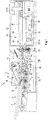
- the 1 to 4 show a device 1 in four method / processing steps for franking and / or imaging packages 2, which are stacked one above the other in a feeder 3 of a separating device 4 before they leave the feeder 3.
- Fig. 1 illustrates the device 1 when pulling off the lowermost package 2 of the four packages 2 stacked inclined in the feeder 3 in the conveying direction F, the remaining three 2 of which are guided on a stop face 5 on a front edge.
- Feeder 3 and separating device 4 form a separating station on the device, in which the packages 2 are pulled off / removed from the underside of the stack 7 and transported in the conveying direction F on a subsequent conveyor path 8, the individual packages 2 of a stack 7 having different thicknesses and / or can have format sizes.
- the conveyor track 8 has two transport rollers 9, 10 which form a flat / slightly inclined conveying plane of the conveying track 8 and which carry the separated mailpieces 2 and which are arranged one behind the other and are driven in the same direction transverse to the conveying direction F.
- the transport rollers 9, 10 advantageously have the same diameter and the same peripheral speed.
- the transport rollers 9, 10 are mounted at their lateral ends in a housing 11 or frame of the device 1 and driven by a motor.
- the packages 2 placed in the feeder 3 are captured on the conveyor roller 10 by an adjusting element 13 of the separating device 4, and the packages 2 occurring above the lowest package 2 are retained in the feeder 3, so that multiple deductions are prevented.
- the upper conveyor roller 16 sits freely and resiliently on the lower 15 and forms a frictional conveyor gap with the latter.
- the packages 2 reach the separating device 4 with the front edge 17 in the transport direction F in each case in the correct position or evenly aligned with the support of the backward inclined stop surface 5 of the feeder 3, which extends approximately over the width of the conveying plane.
- the lower edge 18 of the stop surface 5, which forms the outlet opening 12 with the conveying plane 19, is bent in the conveying direction F, so that the outlet opening 12 remains undisturbed during the transport of the packages 2.
- a docking station of the present embodiment is in the aforementioned EP 17 405 030 described.
- Fig. 1 also represents the conveyor level 19 in the length of the conveyor section 8, which ends in a franking machine 20. Between the separation station 6 and at the end and the franking machine 20 there is a space below the conveying path 8 / conveying plane 19 which serves as a storage device 21 for the printed packages 2 returned by the franking machine 20.
- the filing device 21 extends beyond the conveying plane 19 and is formed by an upper guide plate 22, which is located at the end of the separating station 6 or. Separating device 4 along which extends approximately parallel to the conveyor path 8 and at least approximately to the franking machine 20.
- the mouth of the conveyor section 8 into the franking machine 20 is formed by a pair of conveyor rollers 24 which are arranged one above the other, forming an approximately horizontally and transversely to the conveying direction F conveyor gap, the lower conveyor roller 25 driven and the upper conveyor roller 26 supported on this by spring pressure ( Tension spring 27) is supported.
- the storage device 21 located below the guide plate 22 has a storage shelf 28 for the printed shipping items 2 arriving from the franking machine 20, which are / are placed one above the other.
- a switch 29 which acts on the packages 2 and ensures that on the one hand the packages 2 intended for franking on the conveying path between the separating device 4 or station 6 reach the franking machine 20 without problems and on the other hand keep the way back of the mailpieces 2 printed in the franking machine 20 into the storage device 21 below the switch 29.
- the in the 1 to 4 Turnout 29 shown (rotating device) consists of a switch tongue 30 which can be pivoted about a horizontal axis 47 which runs transversely to the conveying direction F and which can be pivoted upwards, preferably on the guide plate 22, by means of an uneven weight distribution on the axis 47, so that it is opposite one on the supplied mailpieces 2 painting guide tongue 31 and the heavier counter element 32 on the opposite side of the axis 47, an upward deflection effect occurs, which counteracts the continuous mailpieces 2 and thus one Use leadership aids.
- the switch tongue 30 could also be controlled in a motorized manner (in cycles), in particular for processing very thin packages, which may have insufficient rigidity for the lateral movement of the guide tongue 31 of the switch tongue 30 away from the guide plate 22 to form a conveyor gap.
- the upwardly deflecting switch tongue 30 serves the shipping items 2 and the delivery device 21 fed from the franking machine 20. keeps the conveying path free in the storage device 21. That is, the supplied packages 2 slide along / respectively. between the guide plate 22 and the guide tongue 31 or the conveyor path 8 between the conveyor rollers 25, 26 and are transported by these through a rear housing opening 33 into the franking machine 20, for which purpose a housing opening 34 connected for conveying purposes is provided in the latter.
- the conveying speed of the mail items 2 into the franking machine 20 corresponds at least approximately to the speed on the conveyed path.
- Fig. 1 shows two printed packages 2 located on the storage shelf 28 of the storage device 21.
- the conveying end of the conveying path 8 forms the printing position of a shipping item 2 in the franking machine 20.
- the 1 to 4 the main thing is to convey one with a singling station 6 and a storage device 21 assembled / assembled franking machine 20 for the processing of mail items 2 stackable in a feeder 3.
- Fig. 1 the franking machine 20 is shown in a largely non-operational state (without a shipping item).
- An approximately horizontal shaft 35 can be seen, to which the packages 2 are each individually fed in the conveying direction F up to an end stop 36.
- the print head 41 of a printing unit 37 which is guided on horizontal guide rails 38, is in a rest or starting position of the printing unit 37, away from the printing / franking position.
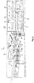
- Fig. 2 illustrates the device 1 in a processing situation in which the separated shipping item 2 on the conveyor line 8 has reached the transfer area 39 between the separating device 4 / separating station 6 and the franking machine 20.
- the package 2 is supported, as can be seen, on the guide tongue 31 of the switch tongue 30, so that it subsequently reaches the conveying gap formed by the conveyor rollers 25, 26 and is transported in the guide shaft 35 intended for franking and imaging (see also Fig. 3 ).
- Fig. 2 shows the lower layer caused by the continuous package 2 of the switch tongue 30 respectively. the tip or the free end of the guide tongue 31.
- the lower position of the guide tongue 31 is determined / limited by the counterweight 40 which is in contact with a stationary stop 42, the stop 42 being fastened to the housing 11 of the separating device 4 or another available part is.
- the position of the switch tongue 30 indicates that the printed packages 2 are ejected from the franking machine 20 into the storage device 21 is not promising, the print head still being in the rest position of the franking machine 20.
- the switch tongue 30 could be mounted in the counterweight 40 or in the stop 42, an adjusting and adjusting screw 43, which adjoins the free end on the stop 42 or on the counterweight 40 so that the position of the guide tongue 31 or. the switch tongue 30 can be changed.
- a process or processing step further has according to Fig. 3 that previously in Fig. 1 detected package 2 first target, the guide shaft 35 in the franking machine 20, the printing position, and the print head 41 of the printing unit 37 is in the working position above the guide shaft 35 or. above the supplied package 2.
- the print head is triggered from the rest position into the operating position, preferably before the shipping item 2 arrives at the end stop 36.
- the package 2 remains held during printing between the conveyor rollers 25, 26, which are rotatable in both directions, the lower conveyor roller 25 being rotatable in both directions, around the package 2 which has arrived in the conveyor gap with the front edge in the guide shaft 35 of the printing unit 37 to be transported and printed from the shaft 35 or placed in the storage device 21.
- the preferably spring-loaded, resting upper conveyor roller 26 serves for a frictional connection for the application of the transport movement in the conveyor shaft 35.
- the print head 41 in the franking machine 20 is driven by a traction mechanism 44 with an endless toothed belt 45 which rotates around two deflection rollers 46 spaced apart from one another and with one strand of which the print head 41 is drive-connected.
- Fig. 4 provides the transportation of the originally according Fig. 1 the shipping item 2 removed in the feeder 3 on the transport from the printing unit 37 of the franking machine 20.
- the printing head 41 has moved back into the rest position.
- the printed package 2 moves into the storage device 21, in which two printed copies have already been placed one above the other.
- the guide tongue 31 of the switch tongue 30 has been lifted upwards by the counterweight 40 and is in contact with the guide plate 22 without disturbing the trajectory of a printed package 2.
- the switch tongue 30 is aligned on the one hand during the clocked feeding through the shipping pieces 2 according to the conveyor gap of the conveyor roller pair 23 (see Fig. 2 ) and after intermittent suspension of the separation in feeder 3 to release the transport space in the storage device 21 upwards.
Landscapes
- Engineering & Computer Science (AREA)
- Mechanical Engineering (AREA)
- Physics & Mathematics (AREA)
- General Physics & Mathematics (AREA)
- Computer Security & Cryptography (AREA)
- Separation, Sorting, Adjustment, Or Bending Of Sheets To Be Conveyed (AREA)
- Sorting Of Articles (AREA)
Abstract
Description
- Die Erfindung betrifft ein Verfahren zum Frankieren von auf einer Förderstrecke einer Frankiermaschine von einem Stapel einzeln zugeführten Versandstücken wie Briefumschläge, Versand-taschen, Hüllen, Karten, Etiketten, Druckproduckte oder dgl., die an der Unterseite des Stapels zur Vereinzelung abgezogen und auf der vorgeschalteten Förderstrecke einem Druckwerk der Frankiermaschine zugeführt und nach dem Bedrucken der Versandstücke aus der Frankiermaschine abgeführt werden.
- Bei den Hüllen sind u.a. verschliessbare Taschen aus (Halb)Karton für flache, insbesondere dünne Produkte wie beispielsweise Druckprodukte, CD's oder andere formatähnliche Artikel gemeint.
- Die Versandstücke lassen sich selbstverständlich einzeln manuell über eine Anlegervorrichtung aufgeben.
- Einrichtungen der eingangs beschriebenen Art sind in den Europäischen Patentanmeldungen
EP 17 405 029 EP 17 405 030 EP 17 405 031 EP 17 405 029 - Bei der
EP 17 405 030 - Die
EP 17 405 031 - Es hat sich in Kenntnis des Standes der Technik die Aufgabe gestellt, ein Verfahren und eine nach diesem hergestellte Einrichtung zur Verarbeitung von Versandstücken zu schaffen, die durch eine einfache Methode und einfache Konstruktionsmittel zuverlässig funktioniert und zu günstigen Bedingungen herstellbar ist.
- Erfindungsgemäss wurde die Aufgabe dadurch gelöst, dass die Versandstücke auf dem Förderabschnitt über eine Weiche der Frankiermaschine zugeführt und nach dem Bedrucken entgegengesetzt zur Zuführrichtung aus dem Druckwerk der Frankiermaschine über die umgestellte Weiche einer unterhalb dieser vorgesehenen Ablagevorrichtung für bedruckte Versandstücke rückgeführt werden.
- In der Druckverarbeitungsindustrie wird eine Ablagevorrichtung auch Auslage bezeichnet.
- Mit dieser Vorgehensweise kann eine vereinfachte Verarbeitung und weitestgehend störungsfreie Überführung der Versandstücke in die Frankiermaschine und eine entgegengesetzte Rückführung bei umgestellter Weiche in eine Ablagevorrichtung, auch Auslage bezeichnet, erreicht werden.
- Diese Methode gestattet eine einfachere und kompaktere Bauweise der Einrichtung als bisher.
- Eine taktweise Verarbeitung der Versandstücke begünstigt eine Kontrolle und Zuverlässigkeit im Ergebnis.
- Vorteilhaft erfolgt die Betätigung der Weiche resp. die Weichenstellung bei der Zuführung der Versandstücke im Takt der Druckfolge des Druckwerks der Frankiermaschine, sodass ein störungsfreier Ablauf der Produktion entstehen kann.
- Vorzugsweise ist eine selbsttätige Weichenzunge zur Umstellung der Weiche vorgesehen, die die Zuführung der Versandstücke zur Frankiermaschine und die Rückführung der bedruckten Versandstücke in die Ablagevorrichtung steuert.
- Alternativ kann die Weichenzunge durch eine Vorrichtung zur Umstellung gesteuert werden.
- Eine Einrichtung zum Frankieren/Bebildern von Versandstücken nach dem vorstehenden Verfahren, mit aus einem die Versandstücke zur Verarbeitung aufnehmenden Anleger, in dem die Versandstücke übereinanderliegend/aneinandergereiht, vorzugsweise an einer Seite geführt sind und jeweils durch eine Vereinzelungsvorrichtung vom Stapel getrennt und hintereinander in Förderrichtung F der Förderstrecke zugeführt werden, erweist sich zur Verarbeitung von Versandstücken als besonders geeignet, wenn die mit der Frankiermaschine förderwirksam verbundene Förderstrecke der Fördereinrichtung einen Förderabschnitt mit einer schaltbaren, zur Führung der Versandstücke auf der Förderstrecke in die, und entgegengesetzt aus der Frankiermaschine, deren Druckwerk, die die Förderrichtung der Versandstücke bestimmende Weichenzunge einer Weiche aufweist, sodass eine kompakte Einheit aus Fördereinrichtung und Frankiermaschine, die als getrennte Frankiermaschine durch manuelles Anlegen der Versandstücke betrieben werden kann.
- Die Einrichtung erweist sich als besonders zuverlässig, wenn die Weichenzunge zur Führung der Versandstücke auf dem Förderabschnitt der Förderstrecke sich quer zur Förderrichtung erstreckend, absenkbar und zur Beschickung der Ablagevorrichtung (Auslage) anhebbar ausgebildet ist, sodass ein störungsfreier Transport der Versandstücke zur Frankiermaschine und in die Ablagevorrichtung entsteht.
- Als einfache Ausführung erweist sich eine Weichenzunge, die um eine quer zur Förderrichtung F angeordnete, horizontale Achse schwenkbar ausgebildet ist, zumal aufgrund der wunschgemäss kompakten Bauweise der Einrichtung wenig Raum für eine mechanisch und präzis funktionierende Vorrichtung zur Verfügung steht.
- Es erweist sich als wirksam und einfach, wenn die Weichenzunge durch eine unregelmässige Gewichtsverteilung an der Achse (Ungleichgewicht) selbsttätig verstellbar zur Führung der Versandstücke auf der Förderstrecke resp. dem Förderabschnitt ausgebildet ist und dem Förderabschnitt/der Förderstrecke die erforderliche Stabilität bietet/entgegen bringt.
- Es wirkt effizient, wenn die Weichenzunge im Takt der auf der Förderstrecke der Frankiermaschine zugeführten Versandstücke oder im Takt der druckenden Frankiermaschinegesteuert ist, sodass eine Regelmässigkeit in der Verarbeitung entsteht.
- Vorteilhaft kann die Auslenkung und Einstellung der Weichenzunge durch eine in einem Gegengewicht der Weichenzunge angeordnete und an einem (ortsfesten) Anschlag aufstehende Einstell- und Verstellschraube veränderbar sein, die ein optimales Anpassen der Weiche an die zum Teil unterschiedliche Dicke der Versandstücke auf dem Förderabschnitt ermöglicht/gestattet.
- Das Förderende der Förderstrecke vor der Frankiermaschine ist vorzugsweise durch zwei senkrecht übereinander, einen Förderspalt bildend und ein Druckwerk mit Versandstücken beliefernde, und die bedruckten Versandstücke aus dem Führungsschacht des Druckwerks der Frankiermaschine in entgegengesetzter Richtung entnehmende, um quer zur Förderrichtung angeordnete Achsen umkehrbar drehend steuerbare Förderrollen ausgebildet ist, von denen die untere motorisch angetrieben und gesteuert ist und die obere mit der unteren durch Reibung antriebverbunden ist.
- Es ist vorgesehen, dass eine freistehende auslegerartige Führungszunge der Weichenzunge und eine über der Weiche angeordnete Führungsplatte den Förderabschnitt bilden, sodass ein an die Dicke der durchlaufenden Versandstücke zur optimalen Führung letzterer angepasster Förderquerschnitt entsteht.
- Die Höhe des Förderabschnittes kann durch den ortsfesten Anschlag für das Gegengewicht der Weichenzunge bestimmt sein.
- Zur Begünstigung der Fördereffizienz auf der Förderstrecke kann das Förderende der Vereinzelungsvorrichtung durch ein an der Förderstrecke angeordnetes Förderwalzenpaar übereinander angeordneter Förderwalzen ausgebildet sein, die einen quer zur Förderrichtung F sich erstreckenden, veränderbaren Förderspalt bilden, der mit dem durch die Weiche ausgebildeten Förderabschnitt förderwirksam verbunden ist und die Zuverlässigkeit des Transports der Versandstücke unterstützt.
- Die Ausbildung der Einrichtung eignet sich dazu, dass die Frankiermaschine auch ohne vorgeschaltete Fördereinrichtung durch Handanlegen der einzelnen Versandstücke auskommt, indem die eigenständigen Gehäuse der voneinander trennbar ausgebildeten Fördereinrichtung und Frankiermaschine, die Förderstrecke ersterer mit dem Führungsschacht/Druckschacht der Frankiermaschine verbindende Gehäuseöffnungen aufweisen, die mit dem Förderspalt des Förderrollenpaares förderwirksam verbunden sind, sodass ein manuelles Anlegen der einzelnen Versandstücke möglich ist.
- Nachfolgend wird die Erfindung unter Bezugnahme auf den zitierten resp. den zitierenden Stand der Technik und die Zeichnung, auf die bezüglich aller in der Beschreibung nicht näher erwähnten Einzelheiten verwiesen wird, anhand eines Ausführungsbeispiels erläutert. In der Zeichnung zeigen:
- Fig. 1
- eine Einrichtung zum Frankieren von einer Förderstrecke, zur weiteren Verarbeitung eines an einem Stapel erfassten, zuzuführenden Versandstückes,
- Fig. 2
- die Einrichtung nach
Fig. 1 , bei einem aus dem Stapel abgezogenen Versandstück, - Fig. 3
- die Einrichtung nach den
Fig. 1 und2 , mit dem gemässFig. 2 Abgezogenen Versandstück in dem Druckwerk der Frankiermaschine in der Druckposition und - Fig. 4
- die Einrichtung nach den
Fig. 1 bis 3 , bei der das bedruckte Versandstück die Frankiermaschine verlassen hat und bei der das Druckwerk nach dem Druck in die Ruhestellung zurückversetzt ist. - Die
Fig. 1 bis 4 zeigen eine Einrichtung 1 in vier Verfahrens-/Verarbeitungsschritten zum Frankieren und/oder Bebildern von Versandstücken 2, die in einem Anleger 3 einer Vereinzelungsvorrichtung 4 übereinanderliegend gestapelt sind, bevor sie den Anleger 3 verlassen. -
Fig. 1 veranschaulicht die Einrichtung 1 beim Abziehen des untersten Versandstücks 2 der vier im Anleger 3 in Förderrichtung F geneigt gestapelten Versandstücke 2, deren verbleibende drei 2 an einer vorderen Kante an einer Anschlagfläche 5 geführt sind. Anleger 3 und Vereinzelungsvorrichtung 4 bilden eine Vereinzelungsstation an der Einrichtung, in der die Versandstücke 2 jeweils an der Unterseite des Stapels 7 abgezogen/entnommen und in Förderrichtung F auf einer anschliessenden Förderstrecke 8 weitertransportiert werden, wobei die einzelnen Versandstücke 2 eines Stapels 7 sich unterscheidende Dickenmasse und/oder Formatgrössen aufweisen können. Die Förderstrecke 8 weist zumindest im Bereich der Vereinzelungsstation 6 zwei eine ebene/in Förderrichtung F leicht geneigte Förderebene der Förderstrecke 8 bildende, die vereinzelten Versandstücke 2 tragende Transportwalzen 9, 10 auf, die quer zur Förderrichtung F hintereinander angeordnet und gleichsinnig angetrieben sind. Die Transportwalzen 9, 10 weisen vorteilhaft den gleichen Durchmesser und die gleiche Umfangsgeschwindigkeit auf. Die Transportwalzen 9, 10 sind an ihren seitlichen Enden in einem Gehäuse 11 oder Gestell der Einrichtung 1 gelagert und motorisch angetrieben. - Die durch die Transportwalzen 9, 10 gebildete Förderebene und die darüber in einem Abstand endende Unterkante der Anschlagfläche 5 ergeben eine Austrittsöffnung 12, die durch die Höhenverstellbarkeit der Anschlagfläche 5 veränderbar ist.
- Die in Anleger 3 angelegten Versandstücke 2 werden an der Förderwalze 10 durch ein Anstellorgan 13 der Vereinzelungsvorrichtung 4 erfasst, und die über dem untersten Versandstück 2 vorkommenden Versandstücke 2 im Anleger 3 zurückgehalten, so dass Mehrfachabzüge verhindert werden.
- Sobald das unterste Versandstück 2 zwischen der Förderwalze 10 und dem Anstellorgan 13 erfasst ist, wird es durch die Förderwalze 9, 10 in der Förderebene in Förderrichtung F weitertransportiert und zwischen das an der Förderebene nachfolgende Förderwalzenpaar 14 geführt, von dem zumindest die untere Förderwalze 15 angetrieben ist, die obere Förderwalze 16 freidrehend und nachgiebig auf der unteren 15 sitzt und mit letzterer einen reibungsschlüssigen Förderspalt bildet.
- Die Versandstücke 2 erreichen die Vereinzelungsvorrichtung 4 mit der in Transportrichtung F vorderen Kante 17 jeweils lagegenau bzw. gleichmässig ausgerichtet mit der Unterstützung der nach hinten geneigten Anschlagfläche 5 des Anlegers 3, die sich etwa über die Breite der Förderebene erstreckt.
- Die die Austrittsöffnung 12 mit der Förderebene 19 bildende Unterkante 18 der Anschlagfläche 5 ist in Förderrichtung F abgebogen ausgebildet, damit die Austrittsöffnung 12 beim Transport der Versandstücke 2 störungsfrei bleibt.
- Im Übrigen ist eine Anlegestation der vorliegenden Ausführung in der eingangs erwähnten
EP 17 405 030 -
Fig. 1 stellt weiterhin die Förderebene 19 in der Länge der Förderstrecke 8 dar, die in einer Frankiermaschine 20 endet. Zwischen der Vereinzelungsstation 6 resp. deren Ende und der Frankiermaschine 20 befindet sich unterhalb der Förderstrecke 8/Förderebene 19 ein Raum, der als Ablagevorrichtung 21 für die von der Frankiermaschine 20 zurückgeführten bedruckten Versandstücke 2 dient. Die Ablagevorrichtung 21 reicht über die Förderebene 19 hinaus und ist durch eine obere Führungsplatte 22 ausgebildet, die sich am Ende der Vereinzelungsstation 6 resp. Vereinzelungsvorrichtung 4 entlang der etwa parallel zur Förderstrecke 8 und zumindest annähernd bis an die Frankiermaschine 20 erstreckt. - Die Mündung der Förderstrecke 8 in die Frankiermaschine 20 ist durch ein Förderrollenpaar 24 ausgebildet das übereinanderstehend, einen etwa horizontal und quer zur Förderrichtung F verlaufenden Förderspalt bildend angeordnet ist, wobei die untere Förderrolle 25 angetrieben und die sich auf dieser abstützende obere Förderrolle 26 mittels Federdruck (Zugfeder 27) anhebbar abgestützt ist. Die sich unterhalb der Führungsplatte 22 befindende Ablagevorrichtung 21 weist einen Ablageboden 28 für die von der Frankiermaschine 20 ankommenden bedruckten Versandstücke 2 auf, die übereinander abgelegt werden/sind.
- Im Abstand oberhalb des Ablagebodens 28 und unterhalb der Führungsplatte 22 ist eine auf die Versandstücke 2 wirkende Weiche 29 angeordnet, die dafür sorgt, dass einerseits die zum Frankieren bestimmten Versandstücke 2 auf dem Förderweg zwischen Vereinzelungsvorrichtung 4 bzw. -station 6 die Frankiermaschine 20 störungsfrei erreichen und andererseits den Rückweg der in der Frankiermaschie 20 bedruckten Versandstücke 2 in die Ablagevorrichtung 21 unterhalb der Weiche 29 freihalten.
- Die in den
Fig. 1 bis 4 dargestellte Weiche 29 (Drehvorrichtung) besteht aus einer um eine quer zur Förderrichtung F verlaufende, etwa horizontale Achse 47 schwenkbare Weichenzunge 30, die durch eine ungleichmässige Gewichtsverteilung an der Achse 47 selbsttätig nach oben schwenkbar, vorzugsweise an der Führungsplatte 22 anstellbar ist, sodass gegenüber einem an den zugeführten Versandstücken 2 anstreichende Führungszunge 31 und dem schwereren Gegenelement 32 auf der gegenüberliegenden Seite der Achse 47 ein nach oben gerichteter Auslenkeffekt entsteht, dem die durchlaufenden Versandstücke 2 entgegenwirken und so eine Führungshilfe nutzen. - Selbstverständlich könnte die Weichenzunge 30 auch (taktweise) motorisch angetrieben gesteuert sein, insbesondere zur Verarbeitung sehr dünner Versandstücke, die eine möglicherweise unzureichende Steifigkeit für das seitliche Bewegen der Führungszunge 31 der Weichenzunge 30 von der Führungsplatte 22 weg zur Bildung eines Förderspaltes aufweisen.
- Andererseits dient die nach oben ausschlagende Weichenzunge 30 den der Ablagevorrichtung 21 aus der Frankiermaschine 20 zugeführten Versandstücke 2 resp. hält deren Förderweg in die Ablagevorrichtung 21 frei. D.h., die zugeführten Versandstücke 2 gleiten entlang/resp. zwischen der Führungsplatte 22 und der Führungszunge 31 bzw. der Förderstrecke 8 zwischen die Förderrollen 25, 26 und werden von diesen durch eine rückseitige Gehäuseöffnung 33 hindurch in die Frankiermaschine 20 transportiert, wozu in letzterer eine förderwirksam verbundene Gehäuseöffnung 34 vorgesehen ist.
- Damit entsteht die Möglichkeit einer Frankiermaschine 20 eine Vereinzelungsstation 6/Vereinzelungsvorrichtung 4 vorzuschalten, oder die Frankiermaschine 20 auf eine bekannte Art durch manuelles Anlegen einzelner Versandstücke 2 zu betreiben.
- Die Fördergeschwindigkeit der Versandstücke 2 in die Frankiermaschine 20 entspricht wenigstens annähernd der Geschwindigkeit auf dem zurückgelegten Förderweg.
-
Fig. 1 zeigt zwei auf dem Ablageboden 28 der Ablagevorrichtung 21 sich befindende bedruckte Versandstücke 2. - Das Förderende der Förderstrecke 8 bildet die Druckposition eines Versandstückes 2 in der Frankiermaschine 20.
- Die
Fig. 1 bis 4 vermitteln jedoch zur Hauptsache eine mit einer Vereinzelungsstation 6 und einer Ablagevorrichtung 21 zusammengebaute/zusammenbaubare Frankiermaschine 20 für die Verarbeitung von in einem Anleger 3 stapelbaren Versandstücken 2. - In
Fig. 1 ist die Frankiermaschine 20 in einem weitgehend betriebsfreien Zustand (ohne Versandstück) dargestellt. Ersichtlich ist ein etwa horizontaler Schacht 35, dem die Versandstücke 2 jeweils einzeln in Förderrichtung F bis zu einem Endanschlag 36 zugeführt werden. - In dieser Situation befindet sich der an horizontale Führungsschienen 38 geführte Druckkopf 41 eines Druckwerks 37 in einer Ruhe- oder Ausgangsstellung des Druckwerks 37, entfernt von der Druck-/Frankierposition.
-
Fig. 2 veranschaulicht die Einrichtung 1 in einer Verarbeitungssituation, in der das vereinzelte Versandstück 2 auf der Förderstrecke 8 den Überführungsbereich 39 zwischen Vereinzelungsvorrichtung 4/Vereinzelungsstation 6 und der Frankiermaschine 20 erreicht hat. In diesem Bereich wird das Versandstück 2 -wie ersichtlichan der Führungszunge 31 der Weichenzunge 30 gestützt, sodass es anschliessend den durch die Förderrollen 25, 26 gebildeten Förderspalt erreicht und in den für das Frankieren und Bebildern bestimmten Führungsschacht 35 transportiert wird (siehe auchFig. 3 ). -
Fig. 2 zeigt die durch das durchlaufende Versandstück 2 bewirkte untere Lage der Weichenzunge 30 resp. die Spitze oder das freie Ende der Führungszunge 31. Die untere Lage der Führungszunge 31 wird durch das an einem ortsfesten Anschlag 42 anstehende/auftreffende Gegengewicht 40 bestimmt/begrenzt, wobei der Anschlag 42 an dem Gehäuse 11 der Vereinzelungsvorrichtung 4 oder einem anderen verfügbaren Teil befestigt ist. Die Lage der Weichenzunge 30 gibt an, dass ein Auswerfen der bedruckten Versandstücke 2 aus der Frankiermaschine 20 in die Ablagevorrichtung 21 nicht aussichtsreich ist, wobei sich der Druckkopf weiterhin in der Ruheposition der Frankiermaschine 20 aufhält. - Zur Verstellung oder Justierung der Führungszunge 31 resp. der Weichenzunge 30 könnte im Gegengewicht 40 oder im Anschlag 42 eine Einstell- und Verstellschraube 43 montiert sein, die mit dem freien Ende am Anschlag 42 oder am Gegengewicht 40 verstellbar ansteht, sodass die Position der Führungszunge 31 resp. der Weichenzunge 30 verändert werden kann.
- Ein Verfahren- oder Verarbeitungsschritt weiter, hat gemäss
Fig. 3 , das zuvor inFig. 1 erfasste Versandstück 2 erste Ziel, den Führungsschacht 35 in der Frankiermaschine 20, die Druckposition, erreicht und der Druckkopf 41 des Druckwerks 37 befindet sich in der Arbeitsposition über dem Führungsschacht 35 resp. über dem zugeführten Versandstück 2. - Ausgelöst wird der Druckkopf von der Ruhestellung in die Betriebsstellung vorzugsweise bevor das Versandstück 2 am Endanschlag 36 eintrifft.
- Das Versandstück 2 bleibt während dem Bedrucken zwischen den Förderrollen 25, 26, die in beiden Richtungen drehbar sind, festgehalten, wobei die untere Förderrolle 25 in beiden Richtungen drehbar ist, um das im Förderspalt mit der Vorderkante angekommene Versandstück 2 in den Führungsschacht 35 des Druckwerks 37 zu transportieren und bedruckt dem Schacht 35 zu entnehmen bzw. in die Ablagevorrichtung 21 abzusetzen. Die vorzugsweise federbelastete, aufliegende obere Förderrolle 26 dient einer reibungsschlüssigen Verbindung für das Aufbringen der Transportbewegung im Förderschacht 35.
- Der Antrieb des Druckkopfes 41 in der Frankiermaschine 20 erfolgt über ein Zugmittelgetriebe 44 mit einem um zwei voneinander distanzierte Umlenkrollen 46 umlaufenden, endlosen Zahnriemen 45, mit dessen einen Trum der Druckkopf 41 antriebsverbunden ist.
-
Fig. 4 stellt den Transport des ursprünglich gemässFig. 1 im Anleger 3 abgezogenen Versandstück 2 auf dem Transport aus dem Druckwerk 37 der Frankiermaschine 20 dar. Der Druckkopf 41 ist wieder in die Ruhestellung zurückgefahren. Das bedruckte Versandstück 2 bewegt sich in die Ablagevorrichtung 21, in der schon zwei bedruckte Exemplare übereinander abgelegt sind. Zu diesem Zweck hat sich die Führungszunge 31 der Weichenzunge 30 durch das Gegengewicht 40 nach oben abgehoben und steht an der Führungsplatte 22 an, ohne die Flugbahn eines bedruckten Versandstücks 2 zu stören. Die Weichenzunge 30 wird einerseits bei der getakteten Zuführung durch die Versandstücke 2 nach dem Förderspalt des Förderrollenpaares 23 ausgerichtet (sieheFig. 2 ) und nach taktweisem Aussetzen der Vereinzelung in Anleger 3 zur Freigabe des Transportraumes in der Ablagevorrichtung 21 nach oben zurückversetzt.
Claims (15)
- Verfahren zum Frankieren von auf einer Förderstrecke einer Frankiermaschine, vorzugsweise von einem Stapel einzeln zugeführten Versandstücken wie Briefumschläge, Versandtaschen, Hüllen, Karten, Etiketten, Druckproduckte oder dgl., die an der Unterseite des Stapels zur Vereinzelung abgezogen und auf der vorgeschalteten Förderstrecke einem Druckwerk der Frankiermaschine zugeführt und nach dem Bedrucken aus der Frankiermaschine abgeführt werden, dadurch gekennzeichnet, dass die vereinzelten Versandstücke auf einem Förderabschnitt der Förderstrecke über eine Weiche der Frankiermaschine zugeführt und nach dem Bedrucken entgegengesetzt zur Zuführrichtung aus dem Druckwerk der Frankiermaschine über die umgestellte Weiche einer unterhalb dieser angeordneten Ablagevorrichtung für die bedruckte Versandstücke rückgeführt werden.
- Verfahren nach Anspruch 1, dadurch gekennzeichnet, dass die Verarbeitung der Versandstücke taktweise erfolgt.
- Verfahren nach Anspruch 2, dadurch gekennzeichnet, dass die Betätigung der Weiche resp. die Zuführung der Versandstücke im Takt der Druckfolge des Druckwerks der Frankiermaschine erfolgt.
- Verfahren nach Anspruch 2, dadurch gekennzeichnet, dass die Betätigung der Weiche bzw. die Druckfolge der Versandstücke im Takt der Vereinzelung der Versandstücke erfolgt.
- Einrichtung (1) zum Frankieren/Bebildern von Versandstücken (2), die an der Unterseite/Vorderseite eines Stapels (7) einzeln abgezogen und auf einer Förderstrecke (8) einer Frankiermaschine (20) zugeführt und nach dem Druck der Versandstücke (2) aus der Frankiermaschine (20) abgeführt werden, bestehend aus einem die Versandstücke (2) aufnehmenden Anleger (3), in dem die Versandstücke (2) übereinanderliegend/aneinandergereiht, vorzugsweise an einer Seite geführt sind und jeweils durch eine Vereinzelungsvorrichtung (4) vom Stapel (7) getrennt und hintereinander in Förderrichtung (F) der Förderstrecke (8) zugeführt werden, zur Durchführung des Verfahrens nach den Ansprüchen 1 bis 4, dadurch gekennzeichnet, dass die mit der Frankiermaschine (20) förderwirksam verbundene Förderstrecke (8) einen Förderabschnitt (48) mit einer schaltbaren, zur Führung der Versandstücke (2) auf der Förderstrecke (8) in die, und entgegengesetzt aus der Frankiermaschine (20) in eine Ablagevorrichtung (21) ausgebildete, die Förderrichtung (F) der Versandstücke (2) bestimmende Weichenzunge (30) einer Weiche (29) aufweist.
- Einrichtung nach Anspruch 5, dadurch gekennzeichnet, dass die Weichenzunge (30) zur Führung der Versandstücke (2) auf der Förderstrecke (8) sich quer zur Förderrichtung (F) erstreckend, absenkbar und zur Beschickung der Ablagevorrichtung (21) anhebbar ausgebildet ist.
- Einrichtung nach Anspruch 5, dadurch gekennzeichnet, dass die Weichenzunge (30) um eine quer zur Förderrichtung (F) angeordnete Achse (47) schwenkbar ausgebildet ist.
- Einrichtung nach einem der Ansprüche 5 bis 7, dadurch gekennzeichnet, dass die Weichenzunge (30) durch eine unregelmässige Gewichtsverteilung an der Achse (47) selbsttätig verstellbar zur Führung der Versandstücke (2) auf der Förderstrecke (8) ausgebildet ist.
- Einrichtung nach einem der Ansprüche 5 bis 7, dadurch gekennzeichnet, dass die Weichenzunge (30) motorisch angetrieben gesteuert ist.
- Einrichtung nach einem der Ansprüche 5 bis 9, dadurch gekennzeichnet, dass die Weichenzunge (30) im Takt der auf der Förderstrecke (8) der Frankiermaschine (20) zugeführten Versandstücke (2) oder im Takt der druckenden Frankiermaschine (20) gesteuert ist.
- Einrichtung nach einem der Ansprüche 6 bis 10, dadurch gekennzeichnet, dass die Auslenkung der Weichenzunge (30) durch eine in einem Gegengewicht (32, 40) der Weichenzunge (30) angeordnete, an einem Anschlag (42) aufstehende Einstell- und Verstellschraube (43) veränderbar ist.
- Einrichtung nach einem der Ansprüche 5 bis 11, dadurch gekennzeichnet, dass das Förderende der Förderstrecke (8) durch zwei etwa senkrecht übereinander, einen Förderspalt bildend und ein Druckwerk (37) der Frankiermaschine (20) mit Versandstücken (2) beschickende und bedruckte Versandstücke (2) einem Führungsschacht (35) des Druckwerks (37) der Frankiermaschine (20) in entgegengesetzter Richtung entnehmende, um quer zur Förderrichtung angeordnete Achsen umkehrbar drehend steuerbare Förderrollen (25, 26) ausgebildet ist.
- Einrichtung nach einem der Ansprüche 7 bis 12, dadurch gekennzeichnet, dass eine Führungszunge (31) der Weichenzunge (30) und eine über der Weiche (29) angeordnete Führungsplatte (22) den Förderabschnitt (48) bilden.
- Einrichtung nach einem der Ansprüche 5 bis 13, dadurch gekennzeichnet, dass das Förderende der Vereinzelungsvorrichtung (4) durch ein an der Förderstrecke (8) angeordnetes Förderwalzenpaar (14) übereinanderliegender Förderwalzen (15,16) ausgebildet ist, die einen quer zur Förderrichtung (F) sich erstreckenden, veränderbaren Förderspalt bilden, der mit dem durch die Weiche (29) ausgebildeten Förderabschnitt (48) förderwirksam verbunden ist.
- Einrichtung nach einem der Ansprüche 5 bis 14, dadurch gekennzeichnet, dass die Gehäuse der voneinander trennbar ausgebildeten Fördereinrichtung und Frankiermaschine (20), die Förderstrecke (8) mit dem Führungsschacht (35) verbindende Gehäuseöffnungen (33, 34) aufweisen, die mit dem Förderspalt des Förderrollenpaares (23) förderwirksam verbunden sind.
Priority Applications (3)
| Application Number | Priority Date | Filing Date | Title |
|---|---|---|---|
| EP18405019.3A EP3623327B1 (de) | 2018-09-11 | 2018-09-11 | Verfahren zum frankieren von auf einer förderstrecke einer frankiermaschine zugeführten versandstücken, und dazugehörige einrichtung |
| CN201910815517.9A CN110884922B (zh) | 2018-09-11 | 2019-08-30 | 用于对从堆叠中单个地输入到盖印机的寄送件进行盖印的方法 |
| US16/567,826 US11420840B2 (en) | 2018-09-11 | 2019-09-11 | Method for franking packages individually supplied from a stack by a franking machine |
Applications Claiming Priority (1)
| Application Number | Priority Date | Filing Date | Title |
|---|---|---|---|
| EP18405019.3A EP3623327B1 (de) | 2018-09-11 | 2018-09-11 | Verfahren zum frankieren von auf einer förderstrecke einer frankiermaschine zugeführten versandstücken, und dazugehörige einrichtung |
Publications (2)
| Publication Number | Publication Date |
|---|---|
| EP3623327A1 true EP3623327A1 (de) | 2020-03-18 |
| EP3623327B1 EP3623327B1 (de) | 2021-07-07 |
Family
ID=63642928
Family Applications (1)
| Application Number | Title | Priority Date | Filing Date |
|---|---|---|---|
| EP18405019.3A Active EP3623327B1 (de) | 2018-09-11 | 2018-09-11 | Verfahren zum frankieren von auf einer förderstrecke einer frankiermaschine zugeführten versandstücken, und dazugehörige einrichtung |
Country Status (3)
| Country | Link |
|---|---|
| US (1) | US11420840B2 (de) |
| EP (1) | EP3623327B1 (de) |
| CN (1) | CN110884922B (de) |
Citations (2)
| Publication number | Priority date | Publication date | Assignee | Title |
|---|---|---|---|---|
| US4893249A (en) * | 1987-12-17 | 1990-01-09 | Pitney Bowes, Inc. | Mailing machine |
| US20140145396A1 (en) * | 2010-07-05 | 2014-05-29 | Nidec Sankyo Corporation | Medium Feeding Direction Switching Mechanism and Medium Issuing and Collecting Device |
Family Cites Families (10)
| Publication number | Priority date | Publication date | Assignee | Title |
|---|---|---|---|---|
| IT1071379B (it) * | 1976-09-22 | 1985-04-02 | Olivetti & Co Spa | Alimentatore di fogli per un sistema di scrittura e simili macchine per scrivere |
| JPH04256643A (ja) * | 1991-02-01 | 1992-09-11 | Canon Inc | 画像形成装置 |
| US5762431A (en) * | 1997-02-10 | 1998-06-09 | Datacard Corporation | Thermal printer and method for using |
| JPH10330012A (ja) * | 1997-05-27 | 1998-12-15 | Fujitsu Ltd | プリンタ、スタッカユニット及びスタッカユニットを含むプリンタ |
| CN107618925B (zh) * | 2016-07-13 | 2020-01-07 | 精工爱普生株式会社 | 后处理装置、印刷系统 |
| US10124974B1 (en) * | 2017-05-11 | 2018-11-13 | Kabushiki Kaisha Toshiba | Paper feeding device, image forming apparatus and paper feeding method |
| US10639914B2 (en) * | 2017-07-07 | 2020-05-05 | Zih Corp. | Rejected media unit storage for media processing devices |
| EP3489022B1 (de) | 2017-11-22 | 2020-09-02 | Frama AG | Einrichtung zum bedrucken von einem druckwerk einzeln zugeführten versandstücken |
| EP3489911B1 (de) | 2017-11-22 | 2022-07-13 | Frama AG | Einrichtung zum frankieren von einzeln oder von einem angelegten stapel transportierten, flachen versandstücken auf einer verarbeitungsstrecke |
| EP3489177B1 (de) | 2017-11-22 | 2024-07-24 | Frama AG | Einrichtung zum vereinzeln von einer frankiermaschine auf einer verarbeitungsstrecke zugeführten versandstücken |
-
2018
- 2018-09-11 EP EP18405019.3A patent/EP3623327B1/de active Active
-
2019
- 2019-08-30 CN CN201910815517.9A patent/CN110884922B/zh active Active
- 2019-09-11 US US16/567,826 patent/US11420840B2/en active Active
Patent Citations (2)
| Publication number | Priority date | Publication date | Assignee | Title |
|---|---|---|---|---|
| US4893249A (en) * | 1987-12-17 | 1990-01-09 | Pitney Bowes, Inc. | Mailing machine |
| US20140145396A1 (en) * | 2010-07-05 | 2014-05-29 | Nidec Sankyo Corporation | Medium Feeding Direction Switching Mechanism and Medium Issuing and Collecting Device |
Also Published As
| Publication number | Publication date |
|---|---|
| US11420840B2 (en) | 2022-08-23 |
| CN110884922A (zh) | 2020-03-17 |
| EP3623327B1 (de) | 2021-07-07 |
| US20200079126A1 (en) | 2020-03-12 |
| CN110884922B (zh) | 2023-01-31 |
Similar Documents
| Publication | Publication Date | Title |
|---|---|---|
| DE2806218A1 (de) | Vorrichtung und verfahren zum beladen eines behaelters mit bogenmaterial bei gleichzeitigem auflockern desselben | |
| EP2253566B1 (de) | Vorrichtung zur Beschickung einer Verarbeitungsstrecke mit Druckprodukten | |
| CH643490A5 (de) | Vorrichtung zum zufuehren und ablegen von einzelblaettern fuer eine schreibende buero- oder datenverarbeitungsmaschine. | |
| DE102020107427B4 (de) | Anlage für die Zufuhr von Rohlingen von Umhüllungen zu einer Verpackungslinie | |
| DE2711173B2 (de) | Einrichtung an einer schreibenden oder druckenden Büromaschine zum Beschicken derselben mit Blättern | |
| EP1979256B1 (de) | Vorrichtung zum zusammentragen von flachen gegenständen und zum weiterfördern der zusammengetragenen gegenstände | |
| WO2013117554A1 (de) | Applikatorvorrichtung für wickeletiketten | |
| DE102016108213A1 (de) | Vorrichtung zur Zuführung von Produktträgern und Vorrichtung zum Verschwenken eines Abdeckabschnitts eines Produktträgers | |
| EP3181462A1 (de) | Vorrichtung und verfahren zum aufstecken von ventilsäcken | |
| DE2838896C2 (de) | ||
| EP0059746A1 (de) | Vorrichtung zum stapeln von in einem schuppenstrom anfallenden flächigen erzeugnissen. | |
| DE3336971C2 (de) | Einrichtung zum Stempeln von flachen Gegenständen | |
| DE2403410B2 (de) | Druckvorrichtung | |
| EP2399853A2 (de) | Transportiervorrichtung für flächige Produkte | |
| DE102015217665A1 (de) | Vorrichtung zum Fördern zumindest eines Ladungsträgers und Verfahren zum Betreiben einer derartigen Vorrichtung | |
| EP3489911B1 (de) | Einrichtung zum frankieren von einzeln oder von einem angelegten stapel transportierten, flachen versandstücken auf einer verarbeitungsstrecke | |
| EP2295320B1 (de) | Vorrichtung und Verfahren zum Handhaben von Stapeln aus Druckträgern | |
| EP3623327B1 (de) | Verfahren zum frankieren von auf einer förderstrecke einer frankiermaschine zugeführten versandstücken, und dazugehörige einrichtung | |
| DE69618871T2 (de) | Artikelauswahl- und Verteilungsvorrichtung | |
| EP3489177B1 (de) | Einrichtung zum vereinzeln von einer frankiermaschine auf einer verarbeitungsstrecke zugeführten versandstücken | |
| EP1273542B1 (de) | Einrichtung zum Transport von auf einer Auflage in einem Stapel aufeinanderliegenden Druckprodukten | |
| EP1050499A1 (de) | Vorrichtung zum Zuführen von flächigen Gegenständen zu einer Verarbeitungseinrichtung | |
| DE102010025224B4 (de) | Vorrichtung und Verfahren zum Transportieren von flächigen Produkten | |
| DE19756539C1 (de) | Vorrichtung zum Erzeugen eines Gesamtstapels | |
| EP0806391A1 (de) | Vorrichtung zum Zubringen von Druckereierzeugnissen zu einer Weiterverarbeitungsstelle |
Legal Events
| Date | Code | Title | Description |
|---|---|---|---|
| PUAI | Public reference made under article 153(3) epc to a published international application that has entered the european phase |
Free format text: ORIGINAL CODE: 0009012 |
|
| STAA | Information on the status of an ep patent application or granted ep patent |
Free format text: STATUS: THE APPLICATION HAS BEEN PUBLISHED |
|
| AK | Designated contracting states |
Kind code of ref document: A1 Designated state(s): AL AT BE BG CH CY CZ DE DK EE ES FI FR GB GR HR HU IE IS IT LI LT LU LV MC MK MT NL NO PL PT RO RS SE SI SK SM TR |
|
| AX | Request for extension of the european patent |
Extension state: BA ME |
|
| STAA | Information on the status of an ep patent application or granted ep patent |
Free format text: STATUS: REQUEST FOR EXAMINATION WAS MADE |
|
| 17P | Request for examination filed |
Effective date: 20200819 |
|
| RBV | Designated contracting states (corrected) |
Designated state(s): AL AT BE BG CH CY CZ DE DK EE ES FI FR GB GR HR HU IE IS IT LI LT LU LV MC MK MT NL NO PL PT RO RS SE SI SK SM TR |
|
| GRAP | Despatch of communication of intention to grant a patent |
Free format text: ORIGINAL CODE: EPIDOSNIGR1 |
|
| STAA | Information on the status of an ep patent application or granted ep patent |
Free format text: STATUS: GRANT OF PATENT IS INTENDED |
|
| RIC1 | Information provided on ipc code assigned before grant |
Ipc: B65H 5/06 20060101ALI20210317BHEP Ipc: B65H 3/06 20060101ALI20210317BHEP Ipc: B65H 29/52 20060101ALI20210317BHEP Ipc: G07B 17/00 20060101ALI20210317BHEP Ipc: B65H 31/02 20060101ALI20210317BHEP Ipc: B65H 29/14 20060101AFI20210317BHEP |
|
| INTG | Intention to grant announced |
Effective date: 20210407 |
|
| GRAS | Grant fee paid |
Free format text: ORIGINAL CODE: EPIDOSNIGR3 |
|
| GRAA | (expected) grant |
Free format text: ORIGINAL CODE: 0009210 |
|
| STAA | Information on the status of an ep patent application or granted ep patent |
Free format text: STATUS: THE PATENT HAS BEEN GRANTED |
|
| AK | Designated contracting states |
Kind code of ref document: B1 Designated state(s): AL AT BE BG CH CY CZ DE DK EE ES FI FR GB GR HR HU IE IS IT LI LT LU LV MC MK MT NL NO PL PT RO RS SE SI SK SM TR |
|
| REG | Reference to a national code |
Ref country code: GB Ref legal event code: FG4D Free format text: NOT ENGLISH |
|
| REG | Reference to a national code |
Ref country code: AT Ref legal event code: REF Ref document number: 1408420 Country of ref document: AT Kind code of ref document: T Effective date: 20210715 |
|
| REG | Reference to a national code |
Ref country code: DE Ref legal event code: R096 Ref document number: 502018006006 Country of ref document: DE |
|
| REG | Reference to a national code |
Ref country code: IE Ref legal event code: FG4D Free format text: LANGUAGE OF EP DOCUMENT: GERMAN |
|
| REG | Reference to a national code |
Ref country code: NL Ref legal event code: FP |
|
| REG | Reference to a national code |
Ref country code: LT Ref legal event code: MG9D |
|
| PG25 | Lapsed in a contracting state [announced via postgrant information from national office to epo] |
Ref country code: HR Free format text: LAPSE BECAUSE OF FAILURE TO SUBMIT A TRANSLATION OF THE DESCRIPTION OR TO PAY THE FEE WITHIN THE PRESCRIBED TIME-LIMIT Effective date: 20210707 Ref country code: ES Free format text: LAPSE BECAUSE OF FAILURE TO SUBMIT A TRANSLATION OF THE DESCRIPTION OR TO PAY THE FEE WITHIN THE PRESCRIBED TIME-LIMIT Effective date: 20210707 Ref country code: FI Free format text: LAPSE BECAUSE OF FAILURE TO SUBMIT A TRANSLATION OF THE DESCRIPTION OR TO PAY THE FEE WITHIN THE PRESCRIBED TIME-LIMIT Effective date: 20210707 Ref country code: SE Free format text: LAPSE BECAUSE OF FAILURE TO SUBMIT A TRANSLATION OF THE DESCRIPTION OR TO PAY THE FEE WITHIN THE PRESCRIBED TIME-LIMIT Effective date: 20210707 Ref country code: RS Free format text: LAPSE BECAUSE OF FAILURE TO SUBMIT A TRANSLATION OF THE DESCRIPTION OR TO PAY THE FEE WITHIN THE PRESCRIBED TIME-LIMIT Effective date: 20210707 Ref country code: LT Free format text: LAPSE BECAUSE OF FAILURE TO SUBMIT A TRANSLATION OF THE DESCRIPTION OR TO PAY THE FEE WITHIN THE PRESCRIBED TIME-LIMIT Effective date: 20210707 Ref country code: BG Free format text: LAPSE BECAUSE OF FAILURE TO SUBMIT A TRANSLATION OF THE DESCRIPTION OR TO PAY THE FEE WITHIN THE PRESCRIBED TIME-LIMIT Effective date: 20211007 Ref country code: NO Free format text: LAPSE BECAUSE OF FAILURE TO SUBMIT A TRANSLATION OF THE DESCRIPTION OR TO PAY THE FEE WITHIN THE PRESCRIBED TIME-LIMIT Effective date: 20211007 Ref country code: PT Free format text: LAPSE BECAUSE OF FAILURE TO SUBMIT A TRANSLATION OF THE DESCRIPTION OR TO PAY THE FEE WITHIN THE PRESCRIBED TIME-LIMIT Effective date: 20211108 |
|
| PG25 | Lapsed in a contracting state [announced via postgrant information from national office to epo] |
Ref country code: PL Free format text: LAPSE BECAUSE OF FAILURE TO SUBMIT A TRANSLATION OF THE DESCRIPTION OR TO PAY THE FEE WITHIN THE PRESCRIBED TIME-LIMIT Effective date: 20210707 Ref country code: LV Free format text: LAPSE BECAUSE OF FAILURE TO SUBMIT A TRANSLATION OF THE DESCRIPTION OR TO PAY THE FEE WITHIN THE PRESCRIBED TIME-LIMIT Effective date: 20210707 Ref country code: GR Free format text: LAPSE BECAUSE OF FAILURE TO SUBMIT A TRANSLATION OF THE DESCRIPTION OR TO PAY THE FEE WITHIN THE PRESCRIBED TIME-LIMIT Effective date: 20211008 |
|
| REG | Reference to a national code |
Ref country code: DE Ref legal event code: R097 Ref document number: 502018006006 Country of ref document: DE |
|
| PG25 | Lapsed in a contracting state [announced via postgrant information from national office to epo] |
Ref country code: DK Free format text: LAPSE BECAUSE OF FAILURE TO SUBMIT A TRANSLATION OF THE DESCRIPTION OR TO PAY THE FEE WITHIN THE PRESCRIBED TIME-LIMIT Effective date: 20210707 |
|
| PLBE | No opposition filed within time limit |
Free format text: ORIGINAL CODE: 0009261 |
|
| STAA | Information on the status of an ep patent application or granted ep patent |
Free format text: STATUS: NO OPPOSITION FILED WITHIN TIME LIMIT |
|
| PG25 | Lapsed in a contracting state [announced via postgrant information from national office to epo] |
Ref country code: SM Free format text: LAPSE BECAUSE OF FAILURE TO SUBMIT A TRANSLATION OF THE DESCRIPTION OR TO PAY THE FEE WITHIN THE PRESCRIBED TIME-LIMIT Effective date: 20210707 Ref country code: SK Free format text: LAPSE BECAUSE OF FAILURE TO SUBMIT A TRANSLATION OF THE DESCRIPTION OR TO PAY THE FEE WITHIN THE PRESCRIBED TIME-LIMIT Effective date: 20210707 Ref country code: RO Free format text: LAPSE BECAUSE OF FAILURE TO SUBMIT A TRANSLATION OF THE DESCRIPTION OR TO PAY THE FEE WITHIN THE PRESCRIBED TIME-LIMIT Effective date: 20210707 Ref country code: MC Free format text: LAPSE BECAUSE OF FAILURE TO SUBMIT A TRANSLATION OF THE DESCRIPTION OR TO PAY THE FEE WITHIN THE PRESCRIBED TIME-LIMIT Effective date: 20210707 Ref country code: EE Free format text: LAPSE BECAUSE OF FAILURE TO SUBMIT A TRANSLATION OF THE DESCRIPTION OR TO PAY THE FEE WITHIN THE PRESCRIBED TIME-LIMIT Effective date: 20210707 Ref country code: CZ Free format text: LAPSE BECAUSE OF FAILURE TO SUBMIT A TRANSLATION OF THE DESCRIPTION OR TO PAY THE FEE WITHIN THE PRESCRIBED TIME-LIMIT Effective date: 20210707 Ref country code: AL Free format text: LAPSE BECAUSE OF FAILURE TO SUBMIT A TRANSLATION OF THE DESCRIPTION OR TO PAY THE FEE WITHIN THE PRESCRIBED TIME-LIMIT Effective date: 20210707 |
|
| 26N | No opposition filed |
Effective date: 20220408 |
|
| PG25 | Lapsed in a contracting state [announced via postgrant information from national office to epo] |
Ref country code: LU Free format text: LAPSE BECAUSE OF NON-PAYMENT OF DUE FEES Effective date: 20210911 Ref country code: IT Free format text: LAPSE BECAUSE OF FAILURE TO SUBMIT A TRANSLATION OF THE DESCRIPTION OR TO PAY THE FEE WITHIN THE PRESCRIBED TIME-LIMIT Effective date: 20210707 Ref country code: IE Free format text: LAPSE BECAUSE OF NON-PAYMENT OF DUE FEES Effective date: 20210911 |
|
| P01 | Opt-out of the competence of the unified patent court (upc) registered |
Effective date: 20230424 |
|
| PG25 | Lapsed in a contracting state [announced via postgrant information from national office to epo] |
Ref country code: CY Free format text: LAPSE BECAUSE OF FAILURE TO SUBMIT A TRANSLATION OF THE DESCRIPTION OR TO PAY THE FEE WITHIN THE PRESCRIBED TIME-LIMIT Effective date: 20210707 |
|
| PG25 | Lapsed in a contracting state [announced via postgrant information from national office to epo] |
Ref country code: HU Free format text: LAPSE BECAUSE OF FAILURE TO SUBMIT A TRANSLATION OF THE DESCRIPTION OR TO PAY THE FEE WITHIN THE PRESCRIBED TIME-LIMIT; INVALID AB INITIO Effective date: 20180911 |
|
| PG25 | Lapsed in a contracting state [announced via postgrant information from national office to epo] |
Ref country code: MK Free format text: LAPSE BECAUSE OF FAILURE TO SUBMIT A TRANSLATION OF THE DESCRIPTION OR TO PAY THE FEE WITHIN THE PRESCRIBED TIME-LIMIT Effective date: 20210707 |
|
| PG25 | Lapsed in a contracting state [announced via postgrant information from national office to epo] |
Ref country code: MT Free format text: LAPSE BECAUSE OF FAILURE TO SUBMIT A TRANSLATION OF THE DESCRIPTION OR TO PAY THE FEE WITHIN THE PRESCRIBED TIME-LIMIT Effective date: 20210707 |
|
| REG | Reference to a national code |
Ref country code: AT Ref legal event code: MM01 Ref document number: 1408420 Country of ref document: AT Kind code of ref document: T Effective date: 20230911 |
|
| PG25 | Lapsed in a contracting state [announced via postgrant information from national office to epo] |
Ref country code: AT Free format text: LAPSE BECAUSE OF NON-PAYMENT OF DUE FEES Effective date: 20230911 |
|
| PG25 | Lapsed in a contracting state [announced via postgrant information from national office to epo] |
Ref country code: AT Free format text: LAPSE BECAUSE OF NON-PAYMENT OF DUE FEES Effective date: 20230911 |
|
| PGFP | Annual fee paid to national office [announced via postgrant information from national office to epo] |
Ref country code: DE Payment date: 20250911 Year of fee payment: 8 |
|
| PGFP | Annual fee paid to national office [announced via postgrant information from national office to epo] |
Ref country code: NL Payment date: 20250927 Year of fee payment: 8 |
|
| PGFP | Annual fee paid to national office [announced via postgrant information from national office to epo] |
Ref country code: BE Payment date: 20250925 Year of fee payment: 8 Ref country code: GB Payment date: 20250927 Year of fee payment: 8 |
|
| PGFP | Annual fee paid to national office [announced via postgrant information from national office to epo] |
Ref country code: FR Payment date: 20250926 Year of fee payment: 8 |
|
| PG25 | Lapsed in a contracting state [announced via postgrant information from national office to epo] |
Ref country code: TR Free format text: LAPSE BECAUSE OF FAILURE TO SUBMIT A TRANSLATION OF THE DESCRIPTION OR TO PAY THE FEE WITHIN THE PRESCRIBED TIME-LIMIT Effective date: 20210707 |
|
| REG | Reference to a national code |
Ref country code: CH Ref legal event code: U11 Free format text: ST27 STATUS EVENT CODE: U-0-0-U10-U11 (AS PROVIDED BY THE NATIONAL OFFICE) Effective date: 20251217 |
|
| PGFP | Annual fee paid to national office [announced via postgrant information from national office to epo] |
Ref country code: CH Payment date: 20251217 Year of fee payment: 8 |
|
| PGFP | Annual fee paid to national office [announced via postgrant information from national office to epo] |
Ref country code: AT Payment date: 20260410 Year of fee payment: 5 |