EP3623178B1 - Reifendruckregelanlage mit druckluftversorgung durch eine im inneren eines starren achskörpers ausgebildete druckluftleitung - Google Patents
Reifendruckregelanlage mit druckluftversorgung durch eine im inneren eines starren achskörpers ausgebildete druckluftleitung Download PDFInfo
- Publication number
- EP3623178B1 EP3623178B1 EP19196792.6A EP19196792A EP3623178B1 EP 3623178 B1 EP3623178 B1 EP 3623178B1 EP 19196792 A EP19196792 A EP 19196792A EP 3623178 B1 EP3623178 B1 EP 3623178B1
- Authority
- EP
- European Patent Office
- Prior art keywords
- axle
- stub
- compressed air
- assembly
- groove
- Prior art date
- Legal status (The legal status is an assumption and is not a legal conclusion. Google has not performed a legal analysis and makes no representation as to the accuracy of the status listed.)
- Active
Links
Images

Classifications
-
- B—PERFORMING OPERATIONS; TRANSPORTING
- B60—VEHICLES IN GENERAL
- B60C—VEHICLE TYRES; TYRE INFLATION; TYRE CHANGING; CONNECTING VALVES TO INFLATABLE ELASTIC BODIES IN GENERAL; DEVICES OR ARRANGEMENTS RELATED TO TYRES
- B60C23/00—Devices for measuring, signalling, controlling, or distributing tyre pressure or temperature, specially adapted for mounting on vehicles; Arrangement of tyre inflating devices on vehicles, e.g. of pumps or of tanks; Tyre cooling arrangements
- B60C23/001—Devices for manually or automatically controlling or distributing tyre pressure whilst the vehicle is moving
- B60C23/003—Devices for manually or automatically controlling or distributing tyre pressure whilst the vehicle is moving comprising rotational joints between vehicle-mounted pressure sources and the tyres
- B60C23/00309—Devices for manually or automatically controlling or distributing tyre pressure whilst the vehicle is moving comprising rotational joints between vehicle-mounted pressure sources and the tyres characterised by the location of the components, e.g. valves, sealings, conduits or sensors
- B60C23/00336—Devices for manually or automatically controlling or distributing tyre pressure whilst the vehicle is moving comprising rotational joints between vehicle-mounted pressure sources and the tyres characterised by the location of the components, e.g. valves, sealings, conduits or sensors on the axles
-
- B—PERFORMING OPERATIONS; TRANSPORTING
- B60—VEHICLES IN GENERAL
- B60B—VEHICLE WHEELS; CASTORS; AXLES FOR WHEELS OR CASTORS; INCREASING WHEEL ADHESION
- B60B35/00—Axle units; Parts thereof ; Arrangements for lubrication of axles
-
- B—PERFORMING OPERATIONS; TRANSPORTING
- B60—VEHICLES IN GENERAL
- B60C—VEHICLE TYRES; TYRE INFLATION; TYRE CHANGING; CONNECTING VALVES TO INFLATABLE ELASTIC BODIES IN GENERAL; DEVICES OR ARRANGEMENTS RELATED TO TYRES
- B60C2200/00—Tyres specially adapted for particular applications
- B60C2200/06—Tyres specially adapted for particular applications for heavy duty vehicles
-
- B—PERFORMING OPERATIONS; TRANSPORTING
- B60—VEHICLES IN GENERAL
- B60C—VEHICLE TYRES; TYRE INFLATION; TYRE CHANGING; CONNECTING VALVES TO INFLATABLE ELASTIC BODIES IN GENERAL; DEVICES OR ARRANGEMENTS RELATED TO TYRES
- B60C23/00—Devices for measuring, signalling, controlling, or distributing tyre pressure or temperature, specially adapted for mounting on vehicles; Arrangement of tyre inflating devices on vehicles, e.g. of pumps or of tanks; Tyre cooling arrangements
- B60C23/005—Devices specially adapted for special wheel arrangements
- B60C23/009—Devices specially adapted for special wheel arrangements having wheels on a trailer
Definitions
- the present invention relates to an axle arrangement with a tire pressure control system, the supply line for the compressed air supply of which runs through a compressed air line formed inside a rigid axle body.
- a generic axis arrangement is from the document DE 10 2006 021 712 A1 known.
- the compressed air can be guided through a stub axle from a pressure source on the vehicle outward in the direction of the rim and the tire.
- the stub axle is mounted in two spaced apart wheel bearings.
- the space between the wheel bearings is used to transmit compressed air, which is supplied from the outside via a line connected to the space from a pressure source.
- a possible pressure source is, for example, an external air compressor installed on the vehicle in question or some other type of pressure source.
- the object of the present invention is to create an axle arrangement in which the compressed air is fed through the stub axle, the vehicle width not being increased by the compressed air duct, the components being inexpensive to manufacture and permanently reliable operation being possible.
- the axle body is designed as an axle stub that is pressed in a rotationally fixed manner with an axle swing in a swing-side axle mount, in the axle swing arm and in the axle stub holes connected to one another in the mounting position of the axle stub in the axle mount are present, which are used as a compressed air supply line through the Axle body through from a swing-side connection to a mouth opening in the stub axle, the connection area of the bores being designed as a groove located at the level of the mouth openings of the bores and extending at least partially in the circumferential direction around the outer circumference of the stub axle that connects the mouth openings of the bores in the axle swing arm and in the axle stub.
- the configuration of the compressed air duct according to the invention enables a space-saving, easily and inexpensively manufactured and permanently reliable solution.
- the stub axle and the rocker can be prefabricated so precisely in the area of the axle mount that after the two components have been pressed together, the stub axle is firmly clamped in the axle mount in the swing arm.
- This press fit of the stub axle in the axle receptacle is also sufficiently gas-tight to guide the compressed air from the connection of the supply line on the axle stub to the opening of the bore in the axle stub with no or only a slight pressure loss.
- rocker arm and the stub axle are only pressed together after the holes and the groove have been made in the components, these components can be processed easily and quickly beforehand. In this way, the bores can be made in the components, and the groove can also be milled out of the material of the components.
- the mutually facing mouth openings of the bores in the stub axle and in the axle rocker are connected to one another by a groove located at their height in the assembly position and extending at least partially in the circumferential direction around the outer circumference of the stub axle.
- the groove forms a connecting channel through which the compressed air flows from the hole in the axle swing arm the bore in the stub axle can flow. It is therefore designed in such a way that, in terms of its position and orientation, it connects the mouth openings of the components with one another in the area of the axle receptacle in the assembly position of the components.
- connection channel by extending in the circumferential direction around the outer circumference of the stub axle, makes it possible to bridge a corresponding angular offset between the orifice openings of the bores if the stub axle is not pressed in an exactly angular position in the axle receptacle in which the orifice openings are directly on top of one another.
- smaller or larger angular misalignments can be compensated for. It is no longer necessary to align the stub axle and the axle swing arm precisely during assembly so that the mouth openings of the bores come to lie precisely on top of one another after the components have been pressed. Rather, an approximate alignment is sufficient in which angular misalignments between these two components are compensated for via the groove.
- the groove it is also possible to use the groove to compensate for a possible length offset in the axial direction of the stub axle. If the groove is made so wide that it also bridges a length offset in the axial direction, the compressed air can still flow from the hole in the axle swing arm into the hole in the stub axle, even if the stub axle has not been pressed exactly that far into the axle holder that the mouth openings are in the axial direction at a common height. This also simplifies assembly and reduces the reject rate in production.
- the bore through the rocker can be designed in such a way that it also extends over a larger length section of the rocker, for example along its longitudinal extent. This makes it possible to connect the supply line for the compressed air to the axle swing arm in an area outside the tire flanks.
- the regularly very narrow installation space between the tire flanks located on the inside of the tires facing the frame and the frame of the vehicle can thus be kept free and narrow by conduits for the compressed air, as if without a separate compressed air conduit.
- thermal problems can also arise in this area, which make a compressed air supply via hose appear critical.
- the compressed air flow through the rocker is technically more convincing.
- Rotary feedthroughs which are susceptible to wear, can be dispensed with when the components of the axle body are pressed once.
- the compressed air line routed in the axle beam is also well protected against foreign bodies, dirt and collision damage.
- the groove is located in the inwardly facing surface of the axle receptacle and / or in the outwardly facing circumferential surface of the axle stub. Before these two components are pressed together, a groove can be well milled out in the surface of the respective component, which is even easier with the stub axle because the outer peripheral surface is more easily accessible.
- the groove is designed as a circumferential annular groove.
- annular groove it is no longer necessary to align the rotational position of the components with one another before pressing them. Since the annular groove runs around a full circle, the mouth openings of the bores are always connected to one another after the stub axle has been pressed.
- the bore in the stub axle runs parallel to the axial direction of the stub axle in a first section and transversely to the axial direction in a second section, the inflow end of the second section opening into the groove.
- the compressed air channel in the stub axle can be produced in this way by two straight bores that are easy to make.
- the second section of the bore is arranged outside the load zone of the stub axle.
- This zone of the stub axle represents the load zone in which a hole would weaken the static strength of the stub axle.
- it is advantageous to arrange the second section of the bore in an area outside the load zone for example in the area of the axle mount in which the axle stub is preferably completely or predominantly enclosed by the axle mount.
- a step-shaped shoulder is formed in the axle receptacle and / or the axle stub, against which the axle stub is pressed in the axle receptacle.
- the shoulder forms a stop which ensures that the mouth openings are in a suitable position in the axial direction and also in relation to the groove to one another after pressing the stub axle.
- the axle arrangement according to one of the preceding claims is part of a trailer axle.
- the above embodiments of the invention are particularly suitable for use in trailer axles because the trailers are particularly space-optimized.
- the components built into it In professional daily use under sometimes difficult operating conditions, the components built into it must also be built to be particularly fail-safe and highly resilient.
- Individual trailers for certain applications are equipped with tire pressure regulation systems in order to be able to transport sensitive or dangerous goods under all conditions without breakage.
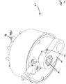
- Fig. 1 a view obliquely from above of an axle assembly 2 is shown.
- the axle swing arm 4 can be clearly seen, which can be attached to the frame of a vehicle such as a trailer with the naked eye.
- the front end of the axle stub 6 can be seen in the axle swing arm 4, which in its installation position is pressed into the axle swing arm 4 via a press fit.
- connection 8 On the axle rocker 4 there is a connection 8 to which a pressure line for supplying compressed air can be connected.
- the connection 8 is located directly above the stub axle 6, but in deviation from the exemplary embodiment, the connection 8 can also be arranged at a different point on the axle rocker 4.
- the compressed air supplied via the connection 8 is led through the axle rocker 4 and the axle stub 6 to the opposite side of the axle assembly 2, where the compressed air is led via the pressure hose 10 to a tire to which the compressed air is to be applied.
- FIG. 2 Fig. 3 is a sectional view through the Fig Fig. 1 Axle arrangement 2 shown is shown.
- the bore 12 which is made in the axle rocker 4, as well as the bore 14, which is guided through the axle stub 6, can be seen.
- the bore 14 in the stub axle 6 is in two parts, with a first section that extends along the longitudinal axis of the stub axle 6 and a second section that extends in a direction transverse to the longitudinal axis of the stub axle 6.
- the two bores 12, 14 have mouth openings 16 facing one another Fig. 2 these two mouth openings 16 are now exactly opposite in the sectional view. According to the invention, however, this is not absolutely necessary.
- the bores 12, 14 are located at the same height in relation to the longitudinal axis of the stub axle 6, so that a groove also running at right angles to the longitudinal axis of the stub axle 6 connects the two mouth openings 16 with one another.
- the matching spatial position of the orifices 16 to one another and to the groove 18 can be ensured by forming a shoulder 22 on the stub axle 6, which when the stub axle 6 is pressed with the axle rocker 4 in the assembly position hits a stop.
- the stub axle 6 has assumed its desired assembly position in the axle receptacle 20.
- the invention is not restricted to the exemplary embodiment described above.
- the person skilled in the art does not have any difficulties in modifying the exemplary embodiment in a manner that appears suitable to him in order to adapt it to a specific application.
Landscapes
- Engineering & Computer Science (AREA)
- Mechanical Engineering (AREA)
- Tires In General (AREA)
Description
- Die vorliegende Erfindung bezieht sich auf eine Achsanordnung mit einer Reifendruckregelanlage, deren Versorgungsleitung für die Druckluftversorgung durch eine im Inneren eines starren Achskörpers ausgebildete Druckluftleitung verläuft.
- Eine gattungsgemäße Achsanordnung ist aus der Schrift
DE 10 2006 021 712 A1 bekannt. In dieser Schrift ist offenbart, dass die Druckluft durch einen Achsstummel hindurch von einer fahrzeugseitigen Druckquelle aus nach außen in Richtung der Felge und des Reifens geführt werden kann. Der Achsstummel ist in zwei beabstandet zueinander angeordneten Radlagern gelagert. Der Zwischenraum zwischen den Radlagern wird zur Übertragung von Druckluft genutzt, die von außen über eine den Zwischenraum angeschlossene Leitung von einer Druckquelle aus herangeführt wird. Als Druckquelle kommt beispielsweise ein auf dem betreffenden Fahrzeug installierter oder sonstiger externer Druckluftkompressor in Betracht. - Es ist zwar vorteilhaft, die Druckluft durch den Achsstummel hindurch in Richtung des Reifens zu leiten, es ist aber schwierig, die Zuführung der Druckluft zum Achsstummel hin so zu gestalten, dass sich eine einfache Montage und ein dauerhaft zuverlässiger Betrieb ergeben. Die in der Schrift
DE 10 2006 021 712 A1 offenbarte Lösung ist praktisch nicht einsetzbar, weil die Druckluft im Zwischenraum das Lagerfett aus den Lagern der Radlager drückt, die Radlager dadurch allmählich trockenlaufen und dadurch einem erhöhten Verschleiß unterliegen, bis sie ganz versagen. - In der Schrift
DE 20 2013 105 026 U1 ist eine Reifendruckregelanlage offenbart, bei der die Drehdurchführungen zur Zuleitung der Druckluft in den Reifen auf der Außenseite der jeweiligen Räder angeordnet sind. Nun ist es aber so, dass die Breite eines Fahrzeugs vom Gesetzgeber vorgegebene Maximalwerte nicht überschreiten darf. Die Fahrzeuge sind häufig zugunsten des nutzbaren Laderaums für sich bereits so breit, dass am Fahrzeug keine weiteren Komponenten mehr angebaut werden können, ohne die maximal zulässigen Grenzwerte zu überschreiten. - Es ist die Aufgabe der vorliegenden Erfindung, eine Achsanordnung zu schaffen, bei der die Zuleitung der Druckluft durch den Achsstummel hindurch erfolgt, wobei die Fahrzeugbreite durch die Druckluftführung nicht vergrößert wird, die Komponenten kostengünstig herstellbar sind und ein dauerhaft zuverlässiger Betrieb möglich ist.
- Die Aufgabe wird gelöst, indem der Achskörper als ein in einer schwingenseitigen Achsaufnahme mit einer Achsschwinge drehfest verpresster Achsstummel ausgebildet ist, in der Achsschwinge und im Achsstummel jeweilige in der Montageposition des Achsstummels in der Achsaufnahme miteinander verbundene Bohrungen vorhanden sind, die als eine Druckluftzuleitung durch den Achskörper hindurch von einem schwingenseitigen Anschluss bis zu einer Mündungsöffnung im Achsstummel dienen, wobei der Verbindungsbereich der Bohrungen als eine in der Höhe der Mündungsöffnungen der Bohrungen befindliche und sich zumindest teilweise in Umfangsrichtung um den Außenumfang des Achsstummels erstreckende Nut ausgebildet ist, die die Mündungsöffnungen der Bohrungen in der Achsschwinge und im Achsstummel miteinander verbindet.
- Die erfindungsgemäße Ausgestaltung der Druckluftführung ermöglicht eine raumsparende, leicht und kostengünstig herstellbare und dauerhaft zuverlässige Lösung. Der Achsstummel und die Schwinge können im Bereich der Achsaufnahme so passgenau vorgefertigt werden, dass sich nach dem Verpressen der beiden Bauteile miteinander ein ausreichend fester klemmender Sitz des Achsstummels in der Achsaufnahme in der Achsschwinge ergibt. Dieser Presssitz des Achsstummels in der Achsaufnahme ist auch hinreichend gasdicht, um die Druckluft ohne einen oder nur mit einem geringem Druckverlust von Anschluss der Zuleitung an der Achsschwinge bis an die Mündungsöffnung der Bohrung im Achsstummel zu leiten.
- Wenn die Achsschwinge und der Achsstummel erst miteinander verpresst werden, nachdem die Bohrungen und die Nut in die Bauteile eingebracht worden sind, können diese Bauteile vorher leicht und schnell bearbeitet werden. So können die Bohrungen in die Bauteile eingebracht werden, und auch die Nut kann aus dem Material der Bauteile ausgefräst werden.
- Die einander zugewandten Mündungsöffnungen der Bohrungen im Achsstummel und in der Achsschwinge werden durch eine in der Montageposition in ihrer Höhe befindliche und sich zumindest teilweise in Umfangsrichtung um den Außenumfang des Achsstummels erstreckende Nut miteinander verbunden. Die Nut bildet einen Verbindungskanal, durch den die Druckluft aus der Bohrung in der Achsschwinge in die Bohrung im Achsstummel strömen kann. Sie ist deshalb so angelegt, dass sie von ihrer Lage und Ausrichtung her die Mündungsöffnungen der Bauteile im Bereich der Achsaufnahme in der Montageposition der Bauteile miteinander verbindet. Der Verbindungskanal ermöglicht es durch seine Erstreckung in Umfangsrichtung um den Außenumfang des Achsstummels, einen entsprechenden Winkelversatz zwischen den Mündungsöffnungen der Bohrungen zu überbrücken, wenn der Achsstummel nicht genau in einer Winkellage in der Achsaufnahme verpresst wird, in der die Mündungsöffnungen direkt aufeinander zu liegen kommen. Je nach Länge, in die sich die Nut in Umfangsrichtung erstreckt, können geringere oder größere Winkelversatze ausgeglichen werden. Es ist nicht mehr erforderlich, den Achsstummel und die Achsschwinge bei der Montage genau so auszurichten, dass die Mündungsöffnungen der Bohrungen nach dem Verpressen der Bauteile genau aufeinander zu liegen kommen. Es genügt vielmehr eine ungefähre Ausrichtung, bei der Winkelversätze zwischen diesen beiden Bauteilen über die Nut ausgeglichen werden.
- Genauso ist es möglich, über die Nut einen eventuellen Längenversatz in axialer Richtung des Achsstummels auszugleichen. Wenn die Nut so breit ausgeführt ist, dass sie auch einen Längenversatz in axialer Richtung überbrückt, kann die Druckluft immer noch von der Bohrung in der Achsschwinge in die Bohrung im Achsstummel strömen, auch wenn der Achsstummel nicht genau so weit in die Achsaufnahme eingepresst worden ist, dass die Mündungsöffnungen in axialer Richtung auf einer gemeinsamen Höhe liegen. Auch hierdurch wird die Montage vereinfacht und die Ausschussquote in der Fertigung gesenkt.
- Die Bohrung durch die Schwinge kann so angelegt sein, dass sie sich auch über einen größeren Längenabschnitt der Schwinge beispielsweise entlang ihrer Längserstreckung erstreckt. Dadurch ist es möglich, die Zuleitung für die Druckluft in einem Bereich außerhalb der Reifenflanken an die Achsschwinge anzuschließen. Der regelmäßig sehr schmale Bauraum zwischen den auf der zum Rahmen weisenden Innenseite der Reifen befindlichen Reifenflanken und dem Rahmen des Fahrzeugs kann dadurch von Leitungsführungen für die Druckluft frei und schmal wie ohne eine gesonderte Druckluftführung gehalten werden. Je nach Bauart der Fahrzeuge können sich in diesem Bereich auch thermische Probleme ergeben, die eine Druckluftführung per Schlauch kritisch erscheinen lassen. Hier ist die Druckluftführung durch die Schwinge hindurch technisch überzeugender.
- Auf verschleißanfällige Drehdurchführungen kann bei der einmaligen Verpressung der Bauteile des Achskörpers verzichtet werden. Die im Achskörper geführte Druckluftleitung ist zudem gut gegen Fremdkörper, Schmutz und Anfahrschäden geschützt.
- Nach einer Ausgestaltung der Erfindung befindet sich die Nut in der nach innen weisenden Oberfläche der Achsaufnahme und/oder in der nach außen weisenden Umfangsfläche des Achsstummels. Vor dem Zusammenpressen dieser beiden Bauteile kann eine Nut gut in der Oberfläche des jeweiligen Bauteils ausgefräst werden, wobei das bei dem Achsstummel noch einfacher ist, weil die Außenumfangsfläche leichter zugänglich ist.
- Nach einer Ausgestaltung der Erfindung ist die Nut als umlaufende Ringnut ausgebildet. Bei einer Ringnut ist es vor dem Verpressen der Bauteile nicht mehr erforderlich, diese in ihrer Rotationslage zueinander auszurichten. Da die Ringnut um einen Vollkreis umläuft, sind die Mündungsöffnungen der Bohrungen nach dem Verpressen des Achsstummels in jedem Fall miteinander verbunden.
- Nach einer Ausgestaltung der Erfindung verläuft die Bohrung im Achsstummel in einem ersten Abschnitt parallel zur axialen Richtung des Achsstummels und in einem zweiten Abschnitt quer zur axialen Richtung, wobei das zuströmungsseitige Ende des zweiten Abschnitts in der Nut mündet. Der Druckluftkanal im Achsstummel kann auf diese Weise durch zwei einfach auszuführende gerade Bohrungen hergestellt werden.
- Nach einer Ausgestaltung der Erfindung ist der zweite Abschnitt der Bohrung außerhalb der Lastzone des Achsstummels angeordnet. Im Übergangsbereich vom Achsstummel zur Achsschwinge wirken Kerbkräfte auf den Achsstummel ein, durch die dieser statisch hoch belastet ist. Diese Zone des Achsstummels stellt die Lastzone dar, in der eine Bohrung die statische Festigkeit des Achsstummels schwächen würde. Um eine Schwächung des Achsstummels zu vermeiden, ist es vorteilhaft, den zweiten Abschnitt der Bohrung in einem Bereich außerhalb der Lastzone anzuordnen, beispielsweise im Bereich der Achsaufnahme, in der der Achsstummel bevorzugt ganz oder überwiegend von der Achsaufnahme umschlossen ist.
- Nach einer Ausgestaltung der Erfindung ist in der Achsaufnahme und/oder dem Achsstummel ein stufenförmiger Absatz ausgebildet, gegen den der Achsstummel in der Achsaufnahme verpresst ist. Der Absatz bildet einen Anschlag, der sicherstellt, dass die Mündungsöffnungen nach dem Verpressen des Achsstummels in einer passenden Lage in axialer Richtung und auch im Verhältnis zur Nut zueinander liegen.
- Nach einer Ausgestaltung der Erfindung ist die Achsanordnung gemäß einem der vorstehenden Ansprüche Bestandteil einer Trailerachse. Die vorstehenden Ausgestaltungen der Erfindung eignen sich besonders für die Anwendung in Trailerachsen, weil die Trailer besonders bauraumoptimiert sind. Im professionellen täglichen Einsatz unter teilweise schwierigen Einsatzbedingungen müssen die darin verbauten Komponenten auch besonders ausfallsicher und hoch belastbar gebaut werden. Einzelne Trailer für bestimmte Anwendungen sind mit Reifendruckregelanlagen ausgestattet, um empfindliche oder gefährliche Güter unter allen Bedingungen ohne Bruchschäden transportieren zu können.
- Weitere Merkmale der Erfindung ergeben sich aus den Ansprüchen, den Figuren und der gegenständlichen Beschreibung. Alle vorstehend in der Beschreibung genannten Merkmale und Merkmalskombinationen sowie die nachfolgend in der Figurenbeschreibung genannten und/oder in den Figuren alleine gezeigten Merkmale und Merkmalskombinationen sind nicht nur in der jeweils angegebenen Kombination, sondern auch in anderen Kombinationen oder aber in Alleinstellung verwendbar.
- Die Erfindung wird nun anhand eines bevorzugten Ausführungsbeispiels sowie unter Bezugnahme auf die beigefügten Zeichnungen näher erläutert. Es zeigen:
- Fig. 1:
- eine Ansicht von schräg oben auf eine Achsanordnung, und
- Fig. 2:
- eine Schnittansicht durch die in
Fig. 1 gezeigte Achsanordnung. - In
Fig. 1 ist eine Ansicht von schräg oben auf eine Achsanordnung 2 gezeigt. In der Ansicht ist gut die Achsschwinge 4 erkennbar, die mit dem freien Auge am Rahmen eines Fahrzeugs wie beispielsweise einem Trailer befestigt werden kann. In der Achsschwinge 4 ist das stirnseitige Ende des Achsstummels 6 erkennbar, der in seiner Einbaulage über eine Presspassung in die Achsschwinge 4 eingepresst ist. - An der Achsschwinge 4 befindet sich ein Anschluss 8, an den eine Druckleitung zur Zuführung von Druckluft angeschlossen werden kann. Im Ausführungsbeispiel befindet sich der Anschluss 8 direkt oberhalb des Achsstummels 6, vom Ausführungsbeispiel abweichend kann der Anschluss 8 aber auch an einer anderen Stelle der Achsschwinge 4 angeordnet sein.
- Die über den Anschluss 8 zugeführte Druckluft wird durch die Achsschwinge 4 und den Achsstummel 6 zur gegenüberliegenden Seite der Achsanordnung 2 geführt, wo die Druckluft über den Druckschlauch 10 zu einem mit der Druckluft zu beaufschlagenden Reifen geführt wird.
- In
Fig. 2 ist eine Schnittansicht durch die inFig. 1 gezeigte Achsanordnung 2 gezeigt. In der Schnittansicht ist die Bohrung 12 erkennbar, die in die Achsschwinge 4 eingebracht ist, sowie die Bohrung 14, die durch den Achsstummel 6 geführt ist. Die Bohrung 14 im Achsstummel 6 ist zweiteilig, und zwar mit einem ersten Abschnitt, der sich entlang der Längsachse des Achsstummels 6 erstreckt, sowie einem zweiten Abschnitt, der sich in einer Richtung quer zur Längsachse des Achsstummels 6 erstreckt. Die beiden Bohrungen 12, 14 haben einander zugewandte Mündungsöffnungen 16. InFig. 2 liegen diese beiden Mündungsöffnungen 16 in der Schnittansicht nun genau gegenüber. Erfindungsgemäß ist das allerdings nicht zwingend erforderlich. Vielmehr befindet sich zwischen den beiden Mündungsöffnungen 16 eine Nut 18, die im Ausführungsbeispiel als eine umlaufende Ringnut ausgebildet ist. Wenn der Achsstummel 6 also in einer anderen Winkellage mit der Achsschwinge 4 verpresst wird, als das inFig. 2 gezeigt ist, kann die in die Bohrung 12 einströmende Druckluft durch die Mündungsöffnung der Bohrung 12 und die Nut 18 zur Mündungsöffnung 16 der Bohrung 14 gelangen, von wo aus die Druckluft dann die gesamte Länge der Bohrung 14 durchströmen kann, um zur Leitung 10 zu gelangen. - In der Schnittansicht ist erkennbar, dass sich die Bohrungen 12, 14 auf derselben Höhe bezogen auf die Längsachse des Achsstummels 6 befinden, so dass eine ebenfalls rechtwinklig zur Längsachse des Achsstummels 6 ausgeführte Nut die beiden Mündungsöffnungen 16 miteinander verbindet. Die passende räumliche Lage der Mündungsöffnungen 16 zueinander sowie zur Nut 18 kann sichergestellt werden, indem an dem Achsstummel 6 ein Absatz 22 ausgebildet ist, der bei der Verpressung des Achsstummels 6 mit der Achsschwinge 4 in der Montageposition gegen einen Anschlag schlägt. In der Schnittzeichnung ist erkennbar, dass der Achsstummel 6 seine gewünschte Montagestellung in der Achsaufnahme 20 eingenommen hat.
- Die Erfindung ist nicht auf das vorstehend beschriebene Ausführungsbeispiel beschränkt. Dem Fachmann bereitet es keine Schwierigkeiten, das Ausführungsbeispiel auf eine ihm als geeignet erscheinende Weise abzuwandeln, um es an einen konkreten Anwendungsfall anzupassen.
Claims (7)
- Achsanordnung (2) mit einer Reifendruckregelanlage, deren Versorgungsleitung für die Druckluftversorgung durch eine im Inneren eines starren Achskörpers ausgebildete Druckluftleitung verläuft, dadurch gekennzeichnet, dass der Achskörper als ein in einer schwingenseitigen Achsaufnahme mit einer Achsschwinge (4) drehfest verpresster Achsstummel (6) ausgebildet ist, in der Achsschwinge (4) und im Achsstummel (6) jeweilige in der Montageposition des Achsstummels (6) in der Achsaufnahme (20) miteinander verbundene Bohrungen (12, 14) vorhanden sind, die als eine Druckluftzuleitung durch den Achskörper hindurch von einem schwingenseitigen Anschluss (8) bis zu einer Mündungsöffnung (16) im Achsstummel (6) dienen, wobei der Verbindungsbereich der Bohrungen (12, 14) als eine in der Höhe der Mündungsöffnungen (16) der Bohrungen (12, 14) befindliche und sich zumindest teilweise in Umfangsrichtung um den Außenumfang des Achsstummels (6) erstreckende Nut (18) ausgebildet ist, die die Mündungsöffnungen (16) der Bohrungen (12, 14) in der Achsschwinge (4) und im Achsstummel (6) miteinander verbindet.
- Achsanordnung (2) nach Anspruch 1, dadurch gekennzeichnet, dass sich die Nut (18) in der nach innen weisenden Oberfläche der Achsaufnahme (20) und/oder in der nach außen weisenden Umfangsfläche des Achsstummels (6) befindet.
- Achsanordnung (2) nach Anspruch 1 oder 2, dadurch gekennzeichnet, dass die Nut (18) als umlaufende Ringnut ausgebildet ist.
- Achsanordnung (2) nach einem der vorgehenden Ansprüche, dadurch gekennzeichnet, dass die Bohrung (14) im Achsstummel (6) in einem ersten Abschnitt parallel zur axialen Richtung des Achsstummels (6) und in einem zweiten Abschnitt quer zur axialen Richtung verläuft, wobei das zuströmungsseitige Ende des zweiten Abschnitts in der Nut (18) mündet.
- Achsanordnung (2) nach Anspruch 4, dadurch gekennzeichnet, dass der zweite Abschnitt der Bohrung (14) außerhalb der Lastzone des Achsstummels (6) angeordnet ist.
- Achsanordnung (2) nach einem der vorgehenden Ansprüche, dadurch gekennzeichnet, dass in der Achsaufnahme (20) und/oder dem Achsstummel (6) ein stufenförmiger Absatz (22) ausgebildet ist, gegen den der Achsstummel (6) in der Achsaufnahme (20) verpresst ist.
- Achsanordnung (2) nach einem der vorgehenden Ansprüche, dadurch gekennzeichnet, dass die Achsanordnung (2) gemäß einem der vorstehenden Ansprüche Bestandteil einer Trailerachse ist.
Applications Claiming Priority (1)
| Application Number | Priority Date | Filing Date | Title |
|---|---|---|---|
| DE102018122413.3A DE102018122413B3 (de) | 2018-09-13 | 2018-09-13 | Reifendruckregelanlage mit Druckluftversorgung durch eine im Inneren eines starren Achskörpers ausgebildete Druckluftleitung |
Publications (2)
| Publication Number | Publication Date |
|---|---|
| EP3623178A1 EP3623178A1 (de) | 2020-03-18 |
| EP3623178B1 true EP3623178B1 (de) | 2020-10-21 |
Family
ID=67400201
Family Applications (1)
| Application Number | Title | Priority Date | Filing Date |
|---|---|---|---|
| EP19196792.6A Active EP3623178B1 (de) | 2018-09-13 | 2019-09-11 | Reifendruckregelanlage mit druckluftversorgung durch eine im inneren eines starren achskörpers ausgebildete druckluftleitung |
Country Status (2)
| Country | Link |
|---|---|
| EP (1) | EP3623178B1 (de) |
| DE (1) | DE102018122413B3 (de) |
Families Citing this family (1)
| Publication number | Priority date | Publication date | Assignee | Title |
|---|---|---|---|---|
| DE102019123511A1 (de) * | 2019-09-03 | 2020-10-01 | Ffg Flensburger Fahrzeugbau Gesellschaft Mbh | Radfahrzeug mit Reifendruckregelanlage |
Family Cites Families (5)
| Publication number | Priority date | Publication date | Assignee | Title |
|---|---|---|---|---|
| US4702843A (en) * | 1985-06-21 | 1987-10-27 | Standard Manufacturing Co., Inc. | Control system for an adverse terrain vehicle |
| DE102006021712B4 (de) | 2006-05-10 | 2012-10-04 | Klaus Müller | Reifenfüllvorrichtung |
| CN103209842B (zh) * | 2010-07-29 | 2016-04-13 | 伊夸莱尔系统公司 | 转向车桥高温报警系统 |
| DE202013105026U1 (de) | 2013-11-08 | 2014-01-29 | Ptg Reifendruckregelsysteme Gmbh | Reifendruckregelanlage für ein Fahrzeug |
| ITUA20162296A1 (it) * | 2016-04-05 | 2017-10-05 | Cnh Ind Italia Spa | Dispositivo di connessione per un assale di un veicolo. |
-
2018
- 2018-09-13 DE DE102018122413.3A patent/DE102018122413B3/de active Active
-
2019
- 2019-09-11 EP EP19196792.6A patent/EP3623178B1/de active Active
Non-Patent Citations (1)
| Title |
|---|
| None * |
Also Published As
| Publication number | Publication date |
|---|---|
| DE102018122413B3 (de) | 2019-08-14 |
| EP3623178A1 (de) | 2020-03-18 |
Similar Documents
| Publication | Publication Date | Title |
|---|---|---|
| DE3446495C2 (de) | Kreuzgelenk für eine Gelenkwelle | |
| DE2520889A1 (de) | Zweiwegeabsperrventil, insbesondere fuer pneumatische kraftfahrzeugbremsanlagen | |
| EP0816703B1 (de) | Konusschraubverbindung für Lamellenpaket-Wellenkupplungen | |
| EP3253645B1 (de) | Lenkstabilisierung | |
| DE102016210221B4 (de) | Aktuator mit einem Schublager für eine Spindel sowie Aktuator für eine Hinterachslenkung | |
| EP3623178B1 (de) | Reifendruckregelanlage mit druckluftversorgung durch eine im inneren eines starren achskörpers ausgebildete druckluftleitung | |
| EP3401129B1 (de) | Reifen-druckbeaufschlagungseinrichtung | |
| EP4375092B1 (de) | Reifendruckventilbaugruppe und gruppe mit reifendruckventilbaugruppen | |
| DE102014218323B4 (de) | Achseinheit | |
| DE102011007231B4 (de) | Radlageranordnung, insbesondere Radlageranordnung für Nutzfahrzeuge | |
| EP3191326B1 (de) | Achseinheit | |
| EP2955040A2 (de) | Lenkerverschraubung eines lenkers eines fahrwerks eines kraftfahrzeugs | |
| DE69411466T2 (de) | Dreharm | |
| EP2363308A1 (de) | Achslenker für eine luftgefederte Fahrzeugachse | |
| DE10120324B4 (de) | Elektropneumatisches Doppelregelventil mit einer Dichtungsanordnung | |
| DE19735753A1 (de) | Drehstabanordnung | |
| DE4225903C2 (de) | Radadapter für Lastfahrzeugräder | |
| DE102017214320B4 (de) | Aktuator einer Hinterachslenkung für ein Kraftfahrzeug | |
| EP3274243B1 (de) | Achseinheit | |
| EP4422882B1 (de) | Anordnung einer nicht rotierenden radblende an einem achsschenkel | |
| DE102013112313A1 (de) | Lenkachse | |
| DE102014105155A1 (de) | Lenkachse | |
| DE69806587T2 (de) | Aufhängung für ein nicht angetriebenes, lenkbares fahrzeugrad | |
| DE102016117164B4 (de) | Achssystem | |
| DE102017126953A1 (de) | Antriebs- und Nachstellvorrichtung einer Trommelbremse |
Legal Events
| Date | Code | Title | Description |
|---|---|---|---|
| PUAI | Public reference made under article 153(3) epc to a published international application that has entered the european phase |
Free format text: ORIGINAL CODE: 0009012 |
|
| STAA | Information on the status of an ep patent application or granted ep patent |
Free format text: STATUS: REQUEST FOR EXAMINATION WAS MADE |
|
| 17P | Request for examination filed |
Effective date: 20200212 |
|
| AK | Designated contracting states |
Kind code of ref document: A1 Designated state(s): AL AT BE BG CH CY CZ DE DK EE ES FI FR GB GR HR HU IE IS IT LI LT LU LV MC MK MT NL NO PL PT RO RS SE SI SK SM TR |
|
| AX | Request for extension of the european patent |
Extension state: BA ME |
|
| GRAP | Despatch of communication of intention to grant a patent |
Free format text: ORIGINAL CODE: EPIDOSNIGR1 |
|
| STAA | Information on the status of an ep patent application or granted ep patent |
Free format text: STATUS: GRANT OF PATENT IS INTENDED |
|
| RIC1 | Information provided on ipc code assigned before grant |
Ipc: B60C 23/00 20060101AFI20200507BHEP Ipc: B60B 35/00 20060101ALI20200507BHEP |
|
| INTG | Intention to grant announced |
Effective date: 20200527 |
|
| GRAS | Grant fee paid |
Free format text: ORIGINAL CODE: EPIDOSNIGR3 |
|
| GRAA | (expected) grant |
Free format text: ORIGINAL CODE: 0009210 |
|
| STAA | Information on the status of an ep patent application or granted ep patent |
Free format text: STATUS: THE PATENT HAS BEEN GRANTED |
|
| AK | Designated contracting states |
Kind code of ref document: B1 Designated state(s): AL AT BE BG CH CY CZ DE DK EE ES FI FR GB GR HR HU IE IS IT LI LT LU LV MC MK MT NL NO PL PT RO RS SE SI SK SM TR |
|
| REG | Reference to a national code |
Ref country code: GB Ref legal event code: FG4D Free format text: NOT ENGLISH |
|
| REG | Reference to a national code |
Ref country code: CH Ref legal event code: EP |
|
| REG | Reference to a national code |
Ref country code: DE Ref legal event code: R096 Ref document number: 502019000316 Country of ref document: DE |
|
| REG | Reference to a national code |
Ref country code: IE Ref legal event code: FG4D Free format text: LANGUAGE OF EP DOCUMENT: GERMAN |
|
| REG | Reference to a national code |
Ref country code: AT Ref legal event code: REF Ref document number: 1325475 Country of ref document: AT Kind code of ref document: T Effective date: 20201115 |
|
| RAP2 | Party data changed (patent owner data changed or rights of a patent transferred) |
Owner name: GIGANT GMBH |
|
| REG | Reference to a national code |
Ref country code: NL Ref legal event code: MP Effective date: 20201021 |
|
| PG25 | Lapsed in a contracting state [announced via postgrant information from national office to epo] |
Ref country code: RS Free format text: LAPSE BECAUSE OF FAILURE TO SUBMIT A TRANSLATION OF THE DESCRIPTION OR TO PAY THE FEE WITHIN THE PRESCRIBED TIME-LIMIT Effective date: 20201021 Ref country code: PT Free format text: LAPSE BECAUSE OF FAILURE TO SUBMIT A TRANSLATION OF THE DESCRIPTION OR TO PAY THE FEE WITHIN THE PRESCRIBED TIME-LIMIT Effective date: 20210222 Ref country code: FI Free format text: LAPSE BECAUSE OF FAILURE TO SUBMIT A TRANSLATION OF THE DESCRIPTION OR TO PAY THE FEE WITHIN THE PRESCRIBED TIME-LIMIT Effective date: 20201021 Ref country code: NO Free format text: LAPSE BECAUSE OF FAILURE TO SUBMIT A TRANSLATION OF THE DESCRIPTION OR TO PAY THE FEE WITHIN THE PRESCRIBED TIME-LIMIT Effective date: 20210121 Ref country code: GR Free format text: LAPSE BECAUSE OF FAILURE TO SUBMIT A TRANSLATION OF THE DESCRIPTION OR TO PAY THE FEE WITHIN THE PRESCRIBED TIME-LIMIT Effective date: 20210122 |
|
| REG | Reference to a national code |
Ref country code: LT Ref legal event code: MG4D |
|
| PG25 | Lapsed in a contracting state [announced via postgrant information from national office to epo] |
Ref country code: SE Free format text: LAPSE BECAUSE OF FAILURE TO SUBMIT A TRANSLATION OF THE DESCRIPTION OR TO PAY THE FEE WITHIN THE PRESCRIBED TIME-LIMIT Effective date: 20201021 Ref country code: PL Free format text: LAPSE BECAUSE OF FAILURE TO SUBMIT A TRANSLATION OF THE DESCRIPTION OR TO PAY THE FEE WITHIN THE PRESCRIBED TIME-LIMIT Effective date: 20201021 Ref country code: LV Free format text: LAPSE BECAUSE OF FAILURE TO SUBMIT A TRANSLATION OF THE DESCRIPTION OR TO PAY THE FEE WITHIN THE PRESCRIBED TIME-LIMIT Effective date: 20201021 Ref country code: IS Free format text: LAPSE BECAUSE OF FAILURE TO SUBMIT A TRANSLATION OF THE DESCRIPTION OR TO PAY THE FEE WITHIN THE PRESCRIBED TIME-LIMIT Effective date: 20210221 Ref country code: BG Free format text: LAPSE BECAUSE OF FAILURE TO SUBMIT A TRANSLATION OF THE DESCRIPTION OR TO PAY THE FEE WITHIN THE PRESCRIBED TIME-LIMIT Effective date: 20210121 Ref country code: ES Free format text: LAPSE BECAUSE OF FAILURE TO SUBMIT A TRANSLATION OF THE DESCRIPTION OR TO PAY THE FEE WITHIN THE PRESCRIBED TIME-LIMIT Effective date: 20201021 |
|
| PG25 | Lapsed in a contracting state [announced via postgrant information from national office to epo] |
Ref country code: NL Free format text: LAPSE BECAUSE OF FAILURE TO SUBMIT A TRANSLATION OF THE DESCRIPTION OR TO PAY THE FEE WITHIN THE PRESCRIBED TIME-LIMIT Effective date: 20201021 Ref country code: HR Free format text: LAPSE BECAUSE OF FAILURE TO SUBMIT A TRANSLATION OF THE DESCRIPTION OR TO PAY THE FEE WITHIN THE PRESCRIBED TIME-LIMIT Effective date: 20201021 |
|
| REG | Reference to a national code |
Ref country code: DE Ref legal event code: R097 Ref document number: 502019000316 Country of ref document: DE |
|
| PG25 | Lapsed in a contracting state [announced via postgrant information from national office to epo] |
Ref country code: CZ Free format text: LAPSE BECAUSE OF FAILURE TO SUBMIT A TRANSLATION OF THE DESCRIPTION OR TO PAY THE FEE WITHIN THE PRESCRIBED TIME-LIMIT Effective date: 20201021 Ref country code: EE Free format text: LAPSE BECAUSE OF FAILURE TO SUBMIT A TRANSLATION OF THE DESCRIPTION OR TO PAY THE FEE WITHIN THE PRESCRIBED TIME-LIMIT Effective date: 20201021 Ref country code: SM Free format text: LAPSE BECAUSE OF FAILURE TO SUBMIT A TRANSLATION OF THE DESCRIPTION OR TO PAY THE FEE WITHIN THE PRESCRIBED TIME-LIMIT Effective date: 20201021 Ref country code: SK Free format text: LAPSE BECAUSE OF FAILURE TO SUBMIT A TRANSLATION OF THE DESCRIPTION OR TO PAY THE FEE WITHIN THE PRESCRIBED TIME-LIMIT Effective date: 20201021 Ref country code: RO Free format text: LAPSE BECAUSE OF FAILURE TO SUBMIT A TRANSLATION OF THE DESCRIPTION OR TO PAY THE FEE WITHIN THE PRESCRIBED TIME-LIMIT Effective date: 20201021 Ref country code: LT Free format text: LAPSE BECAUSE OF FAILURE TO SUBMIT A TRANSLATION OF THE DESCRIPTION OR TO PAY THE FEE WITHIN THE PRESCRIBED TIME-LIMIT Effective date: 20201021 |
|
| PLBE | No opposition filed within time limit |
Free format text: ORIGINAL CODE: 0009261 |
|
| STAA | Information on the status of an ep patent application or granted ep patent |
Free format text: STATUS: NO OPPOSITION FILED WITHIN TIME LIMIT |
|
| PG25 | Lapsed in a contracting state [announced via postgrant information from national office to epo] |
Ref country code: DK Free format text: LAPSE BECAUSE OF FAILURE TO SUBMIT A TRANSLATION OF THE DESCRIPTION OR TO PAY THE FEE WITHIN THE PRESCRIBED TIME-LIMIT Effective date: 20201021 |
|
| 26N | No opposition filed |
Effective date: 20210722 |
|
| PG25 | Lapsed in a contracting state [announced via postgrant information from national office to epo] |
Ref country code: AL Free format text: LAPSE BECAUSE OF FAILURE TO SUBMIT A TRANSLATION OF THE DESCRIPTION OR TO PAY THE FEE WITHIN THE PRESCRIBED TIME-LIMIT Effective date: 20201021 |
|
| PG25 | Lapsed in a contracting state [announced via postgrant information from national office to epo] |
Ref country code: SI Free format text: LAPSE BECAUSE OF FAILURE TO SUBMIT A TRANSLATION OF THE DESCRIPTION OR TO PAY THE FEE WITHIN THE PRESCRIBED TIME-LIMIT Effective date: 20201021 |
|
| REG | Reference to a national code |
Ref country code: DE Ref legal event code: R119 Ref document number: 502019000316 Country of ref document: DE |
|
| REG | Reference to a national code |
Ref country code: BE Ref legal event code: MM Effective date: 20210930 |
|
| PG25 | Lapsed in a contracting state [announced via postgrant information from national office to epo] |
Ref country code: IS Free format text: LAPSE BECAUSE OF FAILURE TO SUBMIT A TRANSLATION OF THE DESCRIPTION OR TO PAY THE FEE WITHIN THE PRESCRIBED TIME-LIMIT Effective date: 20210221 Ref country code: MC Free format text: LAPSE BECAUSE OF FAILURE TO SUBMIT A TRANSLATION OF THE DESCRIPTION OR TO PAY THE FEE WITHIN THE PRESCRIBED TIME-LIMIT Effective date: 20201021 |
|
| PG25 | Lapsed in a contracting state [announced via postgrant information from national office to epo] |
Ref country code: LU Free format text: LAPSE BECAUSE OF NON-PAYMENT OF DUE FEES Effective date: 20210911 Ref country code: IE Free format text: LAPSE BECAUSE OF NON-PAYMENT OF DUE FEES Effective date: 20210911 Ref country code: FR Free format text: LAPSE BECAUSE OF NON-PAYMENT OF DUE FEES Effective date: 20210930 Ref country code: DE Free format text: LAPSE BECAUSE OF NON-PAYMENT OF DUE FEES Effective date: 20220401 Ref country code: BE Free format text: LAPSE BECAUSE OF NON-PAYMENT OF DUE FEES Effective date: 20210930 |
|
| REG | Reference to a national code |
Ref country code: CH Ref legal event code: PL |
|
| PG25 | Lapsed in a contracting state [announced via postgrant information from national office to epo] |
Ref country code: CY Free format text: LAPSE BECAUSE OF FAILURE TO SUBMIT A TRANSLATION OF THE DESCRIPTION OR TO PAY THE FEE WITHIN THE PRESCRIBED TIME-LIMIT Effective date: 20201021 |
|
| PG25 | Lapsed in a contracting state [announced via postgrant information from national office to epo] |
Ref country code: LI Free format text: LAPSE BECAUSE OF NON-PAYMENT OF DUE FEES Effective date: 20220930 Ref country code: HU Free format text: LAPSE BECAUSE OF FAILURE TO SUBMIT A TRANSLATION OF THE DESCRIPTION OR TO PAY THE FEE WITHIN THE PRESCRIBED TIME-LIMIT; INVALID AB INITIO Effective date: 20190911 Ref country code: CH Free format text: LAPSE BECAUSE OF NON-PAYMENT OF DUE FEES Effective date: 20220930 |
|
| PG25 | Lapsed in a contracting state [announced via postgrant information from national office to epo] |
Ref country code: MK Free format text: LAPSE BECAUSE OF FAILURE TO SUBMIT A TRANSLATION OF THE DESCRIPTION OR TO PAY THE FEE WITHIN THE PRESCRIBED TIME-LIMIT Effective date: 20201021 |
|
| PG25 | Lapsed in a contracting state [announced via postgrant information from national office to epo] |
Ref country code: MT Free format text: LAPSE BECAUSE OF FAILURE TO SUBMIT A TRANSLATION OF THE DESCRIPTION OR TO PAY THE FEE WITHIN THE PRESCRIBED TIME-LIMIT Effective date: 20201021 Ref country code: TR Free format text: LAPSE BECAUSE OF NON-PAYMENT OF DUE FEES Effective date: 20210911 |
|
| PGFP | Annual fee paid to national office [announced via postgrant information from national office to epo] |
Ref country code: GB Payment date: 20250923 Year of fee payment: 7 |
|
| REG | Reference to a national code |
Ref country code: AT Ref legal event code: MM01 Ref document number: 1325475 Country of ref document: AT Kind code of ref document: T Effective date: 20240911 |
|
| PG25 | Lapsed in a contracting state [announced via postgrant information from national office to epo] |
Ref country code: AT Free format text: LAPSE BECAUSE OF NON-PAYMENT OF DUE FEES Effective date: 20240911 |
|
| PGFP | Annual fee paid to national office [announced via postgrant information from national office to epo] |
Ref country code: IT Payment date: 20250930 Year of fee payment: 7 |
|
| PGFP | Annual fee paid to national office [announced via postgrant information from national office to epo] |
Ref country code: AT Payment date: 20260410 Year of fee payment: 5 |