EP3621099A2 - Vakuumvorrichtung und verfahren zur fehlerbehebung - Google Patents
Vakuumvorrichtung und verfahren zur fehlerbehebung Download PDFInfo
- Publication number
- EP3621099A2 EP3621099A2 EP19191521.4A EP19191521A EP3621099A2 EP 3621099 A2 EP3621099 A2 EP 3621099A2 EP 19191521 A EP19191521 A EP 19191521A EP 3621099 A2 EP3621099 A2 EP 3621099A2
- Authority
- EP
- European Patent Office
- Prior art keywords
- procedure
- display
- recovery operation
- specimen
- vacuum apparatus
- Prior art date
- Legal status (The legal status is an assumption and is not a legal conclusion. Google has not performed a legal analysis and makes no representation as to the accuracy of the status listed.)
- Granted
Links
Images




Classifications
-
- G—PHYSICS
- G05—CONTROLLING; REGULATING
- G05B—CONTROL OR REGULATING SYSTEMS IN GENERAL; FUNCTIONAL ELEMENTS OF SUCH SYSTEMS; MONITORING OR TESTING ARRANGEMENTS FOR SUCH SYSTEMS OR ELEMENTS
- G05B23/00—Testing or monitoring of control systems or parts thereof
- G05B23/02—Electric testing or monitoring
- G05B23/0205—Electric testing or monitoring by means of a monitoring system capable of detecting and responding to faults
- G05B23/0259—Electric testing or monitoring by means of a monitoring system capable of detecting and responding to faults characterized by the response to fault detection
- G05B23/0286—Modifications to the monitored process, e.g. stopping operation or adapting control
-
- B—PERFORMING OPERATIONS; TRANSPORTING
- B07—SEPARATING SOLIDS FROM SOLIDS; SORTING
- B07C—POSTAL SORTING; SORTING INDIVIDUAL ARTICLES, OR BULK MATERIAL FIT TO BE SORTED PIECE-MEAL, e.g. BY PICKING
- B07C5/00—Sorting according to a characteristic or feature of the articles or material being sorted, e.g. by control effected by devices which detect or measure such characteristic or feature; Sorting by manually actuated devices, e.g. switches
- B07C5/34—Sorting according to other particular properties
-
- B—PERFORMING OPERATIONS; TRANSPORTING
- B07—SEPARATING SOLIDS FROM SOLIDS; SORTING
- B07C—POSTAL SORTING; SORTING INDIVIDUAL ARTICLES, OR BULK MATERIAL FIT TO BE SORTED PIECE-MEAL, e.g. BY PICKING
- B07C5/00—Sorting according to a characteristic or feature of the articles or material being sorted, e.g. by control effected by devices which detect or measure such characteristic or feature; Sorting by manually actuated devices, e.g. switches
- B07C5/36—Sorting apparatus characterised by the means used for distribution
- B07C5/361—Processing or control devices therefor, e.g. escort memory
- B07C5/362—Separating or distributor mechanisms
-
- G—PHYSICS
- G05—CONTROLLING; REGULATING
- G05B—CONTROL OR REGULATING SYSTEMS IN GENERAL; FUNCTIONAL ELEMENTS OF SUCH SYSTEMS; MONITORING OR TESTING ARRANGEMENTS FOR SUCH SYSTEMS OR ELEMENTS
- G05B23/00—Testing or monitoring of control systems or parts thereof
- G05B23/02—Electric testing or monitoring
- G05B23/0205—Electric testing or monitoring by means of a monitoring system capable of detecting and responding to faults
- G05B23/0259—Electric testing or monitoring by means of a monitoring system capable of detecting and responding to faults characterized by the response to fault detection
- G05B23/0267—Fault communication, e.g. human machine interface [HMI]
-
- H—ELECTRICITY
- H01—ELECTRIC ELEMENTS
- H01J—ELECTRIC DISCHARGE TUBES OR DISCHARGE LAMPS
- H01J37/00—Discharge tubes with provision for introducing objects or material to be exposed to the discharge, e.g. for the purpose of examination or processing thereof
- H01J37/02—Details
- H01J37/18—Vacuum locks ; Means for obtaining or maintaining the desired pressure within the vessel
-
- H—ELECTRICITY
- H01—ELECTRIC ELEMENTS
- H01J—ELECTRIC DISCHARGE TUBES OR DISCHARGE LAMPS
- H01J37/00—Discharge tubes with provision for introducing objects or material to be exposed to the discharge, e.g. for the purpose of examination or processing thereof
- H01J37/02—Details
- H01J37/24—Circuit arrangements not adapted to a particular application of the tube and not otherwise provided for
-
- H—ELECTRICITY
- H01—ELECTRIC ELEMENTS
- H01J—ELECTRIC DISCHARGE TUBES OR DISCHARGE LAMPS
- H01J2237/00—Discharge tubes exposing object to beam, e.g. for analysis treatment, etching, imaging
- H01J2237/02—Details
- H01J2237/026—Shields
-
- H—ELECTRICITY
- H01—ELECTRIC ELEMENTS
- H01J—ELECTRIC DISCHARGE TUBES OR DISCHARGE LAMPS
- H01J2237/00—Discharge tubes exposing object to beam, e.g. for analysis treatment, etching, imaging
- H01J2237/26—Electron or ion microscopes
-
- H—ELECTRICITY
- H01—ELECTRIC ELEMENTS
- H01J—ELECTRIC DISCHARGE TUBES OR DISCHARGE LAMPS
- H01J2237/00—Discharge tubes exposing object to beam, e.g. for analysis treatment, etching, imaging
- H01J2237/30—Electron or ion beam tubes for processing objects
Definitions
- the present invention relates to a vacuum apparatus and a recovery support method.
- JP-A-7-36729 discloses a recovery support apparatus which, upon an occurrence of a failure of an electronic apparatus, investigates a cause from collected diagnostic information, reads out corresponding recovery procedures based on the cause of the failure and measures, and displays the recovery procedures on a recovery support screen display unit.
- the invention is capable of providing a vacuum apparatus and a recovery support method which enable a user to easily perform a recovery.
- a vacuum apparatus equipped with an automatic transport mechanism for transporting a specimen and a sensor for detecting a state of the vacuum apparatus, the vacuum apparatus including:
- a recovery support method of a vacuum apparatus equipped with an automatic transport mechanism for transporting a specimen and a sensor for detecting a state of the vacuum apparatus including:
- a transition button for making a transition to a screen showing next procedure of the recovery operation may be enabled, and when an operation of the transition button is performed, the display unit may be caused to display the next procedure.
- FIG. 1 schematically illustrates a vacuum apparatus 1 according to an embodiment of the invention.
- the vacuum apparatus 1 may be configured by omitting a part of the components (units) illustrated in FIG. 1 .
- the vacuum apparatus 1 is a vacuum apparatus provided in an observation apparatus such as an electron microscope, an analysis apparatus such as an electron-probe microanalyzer (EPMA), or a processing apparatus such as a focused ion-beam apparatus (FIB).
- the vacuum apparatus 1 includes a specimen chamber 2, a specimen replacing chamber 3, and a specimen replacing rod 4 provided in the specimen replacing chamber 3.
- the specimen chamber 2 is a space in which a specimen is placed during observation (analysis, processing), and the specimen replacing chamber 3 is a space provided for inserting and removing a specimen to and from the specimen chamber 2 without venting the specimen chamber 2.
- the specimen replacing chamber 3 is configured to be capable of performing pre-evacuation due to an isolation valve 5 being provided on a side of the specimen chamber 2 in the specimen replacing chamber 3 and a replacing chamber door 6 being provided on an atmospheric pressure side in the specimen replacing chamber 3.
- a specimen is mounted to a specimen holder 7, and the specimen holder 7 is mounted to a holder adapter 8.
- the specimen holder 7 and the holder adapter 8 depicted by solid lines in the diagram represent a state where the specimen holder 7 and the holder adapter 8 are on a specimen stage 9 inside the specimen chamber 2, and the specimen holder 7 and the holder adapter 8 depicted by dotted lines in the diagram represent a state where the specimen holder 7 and the holder adapter 8 are inside the specimen replacing chamber 3.
- the specimen stage 9 moves the specimen holder 7 and the holder adapter 8 in a horizontal direction and a vertical direction inside the specimen chamber 2.
- the specimen replacing rod 4 constitutes an automatic transport mechanism which transports (inserts and removes) a specimen between the specimen chamber 2 and the specimen replacing chamber 3 when replacing a specimen.
- the specimen replacing rod 4 is driven by a replacing rod drive motor 10, and a tip section of the specimen replacing rod 4 moves in a lateral direction.
- the tip section of the specimen replacing rod 4 is configured so as to be coupleable to the holder adapter 8.
- the tip section of the specimen replacing rod 4 rotates 90 degrees every time the tip section of the specimen replacing rod 4 is depressed and changes from a vertical state to a horizontal state or from a horizontal state to a vertical state.
- the tip section of the specimen replacing rod 4 in the vertical state comes into contact with the holder adapter 8 and is depressed toward the side of the holder adapter 8, the tip section rotates to assume the horizontal state and is coupled to the holder adapter 8.
- the tip section of the specimen replacing rod 4 in the horizontal state (a state of being coupled to the holder adapter 8) is depressed toward the side of the holder adapter 8
- the tip section rotates to assume the vertical state and the coupling with the holder adapter 8 is released.
- the specimen holder 7 can be transported from the specimen chamber 2 to the specimen replacing chamber 3.
- the specimen replacing chamber 3 is provided with a sensor 11 (a vacuum gauge) which measures pressure in the specimen replacing chamber 3, a sensor 12 which detects whether the replacing chamber door 6 is open or closed, a sensor 13 which detects a rotation state of the tip section of the specimen replacing rod 4 (whether the tip section is in the horizontal state or the vertical state), and sensors 14 and 15 which detect a position of the tip section of the specimen replacing rod 4.
- the sensor 14 can detect that the tip section of the specimen replacing rod 4 is at a left end position (the specimen replacing rod 4 is in a fully contracted state), and the sensor 15 can detect that the tip section of the specimen replacing rod 4 is at a right end position (the specimen replacing rod 4 is in a fully extended state).
- the sensor 13 can detect the rotation state of the tip section of the specimen replacing rod 4 only when the tip section is at the left end position.
- the specimen chamber 2 is provided with a sensor 16 which detects whether the isolation valve 5 is open or closed and a sensor 17 which detects a position of the specimen stage 9 inside the specimen chamber 2.
- the vacuum apparatus 1 is provided with sensors 18 to 21 which detect a position of the holder adapter 8, and among the sensors 18 to 21, the sensors 18 and 19 are provided in the specimen replacing chamber 3, the sensor 20 is provided in a T-shaped section 22 inside the specimen chamber 2, and the sensor 21 is provided on the specimen stage 9.
- the sensors 18 and 19 can detect that the holder adapter 8 is positioned in the specimen replacing chamber 3, the sensor 20 can detect that the holder adapter 8 is positioned between the specimen replacing chamber 3 and the specimen chamber 2 (a position straddling the isolation valve 5), and the sensor 21 can detect that the holder adapter 8 is positioned on the specimen stage 9.
- FIG. 2 illustrates an example of functional block diagrams of the vacuum apparatus 1 described above.
- the vacuum apparatus 1 includes a processing unit 100, an operating unit 110, a detecting unit 120 (sensors), a display unit 130, a drive mechanism 140, and a storage unit 150.
- the operating unit 110 enables a user to input operation information and outputs input operation information to the processing unit 100.
- Functions of the operating unit 110 can be realized by hardware such as a keyboard, a mouse, a button, a touch panel, or a touch pad.
- the detecting unit 120 is sensors that detect a state of the apparatus (the vacuum apparatus 1, the automatic transport mechanism) and includes the sensors 11 to 21. A detection signal of each sensor included in the detecting unit 120 is output to the processing unit 100.
- the display unit 130 displays an image generated by the processing unit 100, and functions of the display unit can be realized by an LCD, a CRT, a touch panel which also functions as the operating unit 110, or the like.
- the drive mechanism 140 includes a drive apparatus (the replacing rod drive motor 10) of the specimen replacing rod 4, a drive apparatus of a vacuum pump, a drive apparatus of a vacuum valve, and a drive apparatus of the specimen stage 9.
- the storage unit 150 stores programs and various data which enable a computer to function as the respective units of the processing unit 100 and functions as a work area of the processing unit 100, and the functions of the storage unit 150 can be realized by a hard disk, a RAM, or the like.
- the processing unit 100 (a computer) performs various processes based on operation information, signals from the detecting unit 120, programs, and the like. Functions of the processing unit 100 can be realized by hardware including various processors (a CPU, DSP, or the like) and by programs.
- the processing unit 100 includes a determining unit 101, a display control unit 102, and a drive control unit 103.
- the determining unit 101 determines whether or not a recoverable error (an error from which recovery is possible by an operation of the user) has occurred based on a signal from one or a plurality of sensors included in the detecting unit 120. For example, data identifying a type of a recoverable error corresponding to a combination of symbols from the respective sensors included in the detecting unit 120 may be stored in the storage unit 150, whereby the determining unit 101 refers to the data based on a combination of symbols from the respective sensors and determines whether or not there is an error corresponding to the combination.
- a recoverable error an error from which recovery is possible by an operation of the user
- the display control unit 102 When it is determined by the determining unit 101 that a recoverable error has occurred, the display control unit 102 performs control for causing the display unit 130 to display, in a wizard format, procedures of a recovery operation in order to recover from the error.
- data for displaying procedures of a recovery operation in a wizard format may be stored in the storage unit 150 in association with a type of each recoverable error, whereby the display control unit 102 reads out data corresponding to a type of the occurred error and causes procedures of a recovery operation in order to recover from the error to be displayed in a wizard format.
- Each procedure of the recovery operation is displayed by a text, a diagram, or a photograph indicating an operation procedure, or a combination thereof.
- the display control unit 102 determines whether or not a recovery operation has been performed according to a procedure being displayed on the display unit 130 based on a signal from one or a plurality of sensors included in the detecting unit 120, and when the display control unit 102 determines that the recovery operation has been performed according to the procedure, the display control unit 102 causes the display unit 130 to display a next procedure of the recovery operation.
- the display control unit 102 may enable a transition button for making a transition to a screen showing a next procedure of the recovery operation, and when an operation with respect to the enabled transition button is performed, the display control unit 102 may cause the display unit 130 to display the next procedure.
- Enabling the transition button means that the transition button is changed from an inoperable state to an operable state.
- the transition button may be changed from a hidden state to a displayed state or the transition button having been displayed translucently may be displayed opaquely.
- the display control unit 102 when the procedures of the recovery operation include a procedure for operating the apparatus, the display control unit 102 causes the display unit 130 to display a control button for operating the apparatus. Furthermore, when the display control unit 102 is unable to determine whether or not a recovery operation has been performed according to a procedure of the recovery operation based on a signal from a sensor included in the detecting unit 120, the display control unit 102 causes the display unit 130 to display an operation procedure for enabling the determination based on a signal from the detecting unit 120.
- the drive control unit 103 outputs a control signal to the drive mechanism 140 and performs control for operating the drive mechanism 140. For example, when an operation for issuing an instruction to insert the specimen holder 7 into the specimen stage 9 is performed by the user, the drive control unit 103 drives the replacing rod drive motor 10 and moves the tip section of the specimen replacing rod 4 being coupled with the holder adapter 8 toward the side of the specimen chamber 2 to transport the specimen holder 7 to the specimen stage 9, and moves the tip section of the specimen replacing rod 4 of which coupling with the holder adapter 8 has been released toward the side of the specimen replacing chamber 3.
- the drive control unit 103 drives the replacing rod drive motor 10 and moves the tip section of the specimen replacing rod 4 not being coupled with the holder adapter 8 toward the side of the specimen chamber 2 to couple the tip section with the holder adapter 8, and moves the tip section of the specimen replacing rod 4 being coupled with the holder adapter 8 toward the side of the specimen replacing chamber 3 to transport the specimen holder 7 to the specimen replacing chamber 3. Furthermore, the drive control unit 103 operates the drive mechanism 140 in accordance with an operation with respect to the control button displayed on a screen of a wizard during recovery.
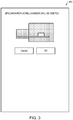
- FIGS. 3 to 9 illustrate examples of a recovery wizard (procedures of a recovery operation displayed in a wizard format) which is displayed on the display unit 130 when a recoverable error occurs.
- the tip section of the specimen replacing rod 4 is detected to be at the left end position according to a signal from the sensor 14, and the tip section of the specimen replacing rod 4 is detected to be in the horizontal state according to a signal from the sensor 13, it is determined that a recoverable error (an abnormality of a rotation state of the tip section of the specimen replacing rod 4) has occurred.
- the tip section of the specimen replacing rod 4 is in the horizontal state, even when the user performs an operation for issuing an instruction to remove the specimen holder 7, the tip section of the specimen replacing rod 4 is not coupled to the holder adapter 8 and the specimen holder 7 cannot be removed. In order to recover from this error, the user must perform a recovery operation that involves manually depressing the tip section of the specimen replacing rod 4 and changing the tip section from the horizontal state to the vertical state.
- FIG. 3 illustrates an initial screen of the recovery wizard.
- a screen 201 illustrated in FIG. 3 displays a diagram representing states of the specimen chamber 2, the specimen replacing chamber 3, and the specimen holder 7. The diagram illustrates that the specimen holder 7 is in the specimen chamber 2 and that the specimen chamber 2 and the specimen replacing chamber 3 are being exhausted.
- the screen 201 displays venting the specimen replacing chamber 3 as a first procedure of the recovery operation.
- the screen 201 displays an "OK" button (a control button), and when the user performs an operation to depress the "OK” button, the vacuum valve is driven after the isolation valve 5 is detected to be closed based on a signal from the sensor 16 and the specimen replacing chamber 3 is vented. It should be noted that when the user performs an operation to depress a "Cancel" button, the recovery wizard is ended.
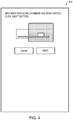
- a transition is made to a screen 202 illustrated in FIG. 4 .
- the diagram displayed on the screen 202 indicates that the specimen replacing chamber 3 has been vented.
- a transition button displayed on the screen 202
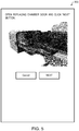
- a transition is made to a screen 203 illustrated in FIG. 5 .
- the screen 203 displays opening the replacing chamber door 6 as a next procedure of the recovery operation and also displays a photograph of the replacing chamber door 6 in an open state.
- a "Next" button (a transition button) displayed on the screen 203 is enabled.
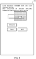
- a transition is made to a screen 204 illustrated in FIG. 6 .
- the screen 204 displays moving the tip section of the specimen replacing rod 4 toward the side of the specimen chamber 2 from the left end position by a predetermined distance (several cm) (changing the tip section of the specimen replacing rod 4 to an IN state) as a next procedure of the recovery operation and also displays a photograph of the tip section in the IN state.
- the screen 204 displays an "IN" button (a control button) for changing the tip section of the specimen replacing rod 4 to the IN state.
- the replacing rod drive motor 10 is driven, the tip section of the specimen replacing rod 4 moves toward the side of the specimen chamber 2 from the left end position by the predetermined distance, and a transition is made to a screen 205 illustrated in FIG. 7 .
- the screen 205 displays manually depressing the tip section of the specimen replacing rod 4 to place the tip section of the specimen replacing rod 4 in the vertical state and subsequently moving the tip section of the specimen replacing rod 4 to the left end position (changing the tip section of the specimen replacing rod 4 to an OUT state) as a next procedure of the recovery operation, and also displays a photograph of a situation where the tip section of the specimen replacing rod 4 is manually depressed, a photograph of the tip section in the vertical state, and a photograph of the tip section in the horizontal state.
- the screen 205 displays an "OUT" button (a control button) for changing the tip section of the specimen replacing rod 4 to the OUT state.
- the replacing rod drive motor 10 is driven and the tip section of the specimen replacing rod 4 is moved to the left end position, and when the tip section of the specimen replacing rod 4 is detected to be in the vertical state based on a signal from the sensor 13, a "Next" button (a transition button) displayed on the screen 205 is enabled.
- the screen 206 displays closing the replacing chamber door 6 and evacuating the specimen replacing chamber 3 as a next procedure of the recovery operation.
- an "Evacuate” button (a control button) displayed on the screen 206 is enabled.
- the vacuum pump is driven and the specimen replacing chamber 3 is evacuated, and when the specimen replacing chamber 3 is detected to be evacuated based on a signal from the sensor 11, a "Next" button (a transition button) displayed on the screen 206 is enabled.
- a transition button is made to a screen 207 illustrated in FIG. 9 .
- the screen 207 displays a message to the effect that recovery has been completed and the specimen holder 7 can be removed by a normal specimen replacement operation (an operation for issuing an instruction to remove the specimen holder 7).
- a normal specimen replacement operation an operation for issuing an instruction to remove the specimen holder 7.
- procedures of a recovery operation are displayed in a wizard format, a determination as to whether or not the recovery operation has been performed according to a displayed procedure is made based on a signal from a sensor, when it is determined that the recovery operation has been performed according to the procedure, a transition button for making a transition to a screen showing a next procedure is enabled, when an operation of the enabled transition button is performed, the screen showing the next procedure is displayed, but when a determination as to whether or not the recovery operation has been performed according to the procedure cannot be determined by the sensor, an operation is guided to a point where the determination can be made by the sensor, and a determination is made as to whether or not the recovery operation has been performed according to the procedure, thereby enabling a user to readily perform the recovery operation without making mistakes.
- procedures of the recovery operation include a procedure for operating the apparatus, by displaying a control button for operating the apparatus,
- the transition button may not be displayed on the screen of the recovery wizard.
- a screen showing a next procedure may be displayed automatically (independent of an operation by the user).
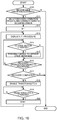
- the determining unit 101 determines whether or not a recoverable error has occurred based on a signal from the detecting unit 120 (the sensors 11 to 21) (step S10).
- the display control unit 102 selects procedures of a recovery operation corresponding to the occurred error from procedures of recovery operations respectively corresponding to a plurality of types of errors (step S11), and sets a variable N to 1 (step S12).
- the display control unit 102 causes the display unit 130 to display a screen showing an N-th procedure of the selected recovery operation (step S13).
- the drive control unit 103 determines whether or not an operation with respect to a control button displayed on the screen has been performed (step S14), and when an operation with respect to the control button has been performed (Y in step S14), the drive control unit 103 performs control for operating the drive mechanism 140 in accordance with the operated control button (step S15).
- the display control unit 102 determines whether or not the recovery operation has been performed according to the N-th procedure being displayed on the display unit 130 based on a signal from the detecting unit 120 (step S16).
- step S14 When the recovery operation has not been performed according to the N-th procedure (N in step S16), a transition is made to step S14.
- the display control unit 102 determines whether or not the recovery has been completed (whether or not all procedures of the recovery operation have been performed) (step S17), and when the recovery has been completed (Y in step S17), the display control unit 102 ends the process.
- step S17 When the recovery has not been completed (N in step S17), the display control unit 102 enables a transition button on the screen (step S18). Next, the display control unit 102 determines whether or not an operation with respect to the enabled transition button has been performed (step S19), and when an operation with respect to the transition button has been performed (Y in step S19), the display control unit 102 adds 1 to the variable N (step S20) and makes a transition to step S13. Subsequently, the process of steps S13 to S20 is repeated until all of the procedures of the recovery operation are performed.
- the invention includes configurations that are substantially the same (for example, in function and method) as the configurations described in the embodiments.
- the invention also includes configurations in which non-essential elements described in the embodiments are replaced by other elements.
- the invention further includes configurations obtained by adding known art to the configurations described in the embodiments.
Landscapes
- Engineering & Computer Science (AREA)
- Chemical & Material Sciences (AREA)
- Analytical Chemistry (AREA)
- Physics & Mathematics (AREA)
- General Physics & Mathematics (AREA)
- Automation & Control Theory (AREA)
- Human Computer Interaction (AREA)
- Automatic Analysis And Handling Materials Therefor (AREA)
- Sampling And Sample Adjustment (AREA)
Applications Claiming Priority (1)
| Application Number | Priority Date | Filing Date | Title |
|---|---|---|---|
| JP2018152838A JP6851348B2 (ja) | 2018-08-15 | 2018-08-15 | 真空装置及び復旧支援方法 |
Publications (3)
| Publication Number | Publication Date |
|---|---|
| EP3621099A2 true EP3621099A2 (de) | 2020-03-11 |
| EP3621099A3 EP3621099A3 (de) | 2020-05-13 |
| EP3621099B1 EP3621099B1 (de) | 2021-05-05 |
Family
ID=67658708
Family Applications (1)
| Application Number | Title | Priority Date | Filing Date |
|---|---|---|---|
| EP19191521.4A Active EP3621099B1 (de) | 2018-08-15 | 2019-08-13 | Vakuumvorrichtung und verfahren zur fehlerbehebung |
Country Status (3)
| Country | Link |
|---|---|
| US (1) | US11260427B2 (de) |
| EP (1) | EP3621099B1 (de) |
| JP (1) | JP6851348B2 (de) |
Citations (1)
| Publication number | Priority date | Publication date | Assignee | Title |
|---|---|---|---|---|
| JPH0736729A (ja) | 1993-07-22 | 1995-02-07 | Toshiba Corp | 復旧支援装置 |
Family Cites Families (13)
| Publication number | Priority date | Publication date | Assignee | Title |
|---|---|---|---|---|
| US4967337A (en) * | 1988-10-11 | 1990-10-30 | Texas Instruments Incorporated | Automated diagnostic system |
| TW309503B (de) * | 1995-06-27 | 1997-07-01 | Tokyo Electron Co Ltd | |
| JP3793707B2 (ja) * | 2001-09-28 | 2006-07-05 | 株式会社日立製作所 | 真空装置の監視装置および監視方法 |
| EP1546827A1 (de) * | 2002-09-30 | 2005-06-29 | Tokyo Electron Limited | Vefahren und vorrichtung zum steuern und überwachen eines prozesses zur herstellung von halbleiterbausteinen |
| JP3858935B2 (ja) * | 2005-09-21 | 2006-12-20 | 株式会社日立製作所 | 監視方法および監視システム |
| US8195418B2 (en) * | 2007-04-25 | 2012-06-05 | Brooks Automation, Inc. | Pressure measurement instrument and method |
| JP2009135433A (ja) * | 2007-11-05 | 2009-06-18 | Hitachi Kokusai Electric Inc | 基板処理装置 |
| US20090114346A1 (en) * | 2007-11-05 | 2009-05-07 | Hitachi Kokusai Electric Inc. | Substrate processing apparatus |
| US8185242B2 (en) * | 2008-05-07 | 2012-05-22 | Lam Research Corporation | Dynamic alignment of wafers using compensation values obtained through a series of wafer movements |
| US8330101B2 (en) * | 2010-01-19 | 2012-12-11 | Agilent Technologies, Inc. | System and method for replacing an ion source in a mass spectrometer |
| US8504313B2 (en) * | 2010-03-22 | 2013-08-06 | Dennis Cardinale | Electronic vacuum gauge and systems and methods of calibration and operation of same |
| WO2012060416A1 (ja) * | 2010-11-05 | 2012-05-10 | 株式会社 日立ハイテクノロジーズ | イオンミリング装置 |
| KR102459432B1 (ko) * | 2015-06-16 | 2022-10-27 | 삼성전자주식회사 | 기판 제조 설비 및 그의 관리 방법 |
-
2018
- 2018-08-15 JP JP2018152838A patent/JP6851348B2/ja active Active
-
2019
- 2019-08-07 US US16/534,065 patent/US11260427B2/en active Active
- 2019-08-13 EP EP19191521.4A patent/EP3621099B1/de active Active
Patent Citations (1)
| Publication number | Priority date | Publication date | Assignee | Title |
|---|---|---|---|---|
| JPH0736729A (ja) | 1993-07-22 | 1995-02-07 | Toshiba Corp | 復旧支援装置 |
Also Published As
| Publication number | Publication date |
|---|---|
| US20200055092A1 (en) | 2020-02-20 |
| JP2020027773A (ja) | 2020-02-20 |
| US11260427B2 (en) | 2022-03-01 |
| JP6851348B2 (ja) | 2021-03-31 |
| EP3621099A3 (de) | 2020-05-13 |
| EP3621099B1 (de) | 2021-05-05 |
Similar Documents
| Publication | Publication Date | Title |
|---|---|---|
| JP4166229B2 (ja) | タッチパネルを備えた表示装置 | |
| JP4901442B2 (ja) | トラブル原因究明支援装置,トラブル原因究明支援方法,プログラムを記憶する記憶媒体 | |
| JP2009211641A (ja) | 入力装置、入力方法およびプログラム | |
| EP3255971B1 (de) | Bildverarbeitungsvorrichtung, montageverarbeitungssystem und bildverarbeitungsverfahren | |
| EP3621099B1 (de) | Vakuumvorrichtung und verfahren zur fehlerbehebung | |
| JPWO2011148719A1 (ja) | 情報処理装置、gui操作支援方法およびgui操作支援プログラム | |
| CN101853105A (zh) | 一种具有触控屏幕的计算机及其操作方法 | |
| JP2016053582A (ja) | 検体測定装置および表示方法 | |
| US6414699B1 (en) | Message box facility for graphical user interface for computer system video display | |
| EP1986095A1 (de) | Verfahren und Vorrichtung zur Hilfeleistung bei falscher Schaltflächenverwendung durch einen Benutzer | |
| EP3617703B1 (de) | Computerlesbarer programmcode und überwachungsvorrichtung zur überwachung eines zustands einer chromatografievorrichtung | |
| CN1908657A (zh) | 色谱数据处理装置 | |
| JP5851637B2 (ja) | 検体処理装置および表示方法 | |
| JP6109103B2 (ja) | プラント監視画面表示装置 | |
| KR20170104446A (ko) | 샘플 스테이지 | |
| US11493917B2 (en) | Remotely operating a machine using a communication device | |
| JP2012173765A (ja) | タッチパネル装置、処理決定方法、プログラムおよびタッチパネルシステム | |
| JP3670317B2 (ja) | オペレーション装置 | |
| JP5883193B2 (ja) | 検体測定装置および表示方法 | |
| US10628005B2 (en) | Image display device, image display method, and information storage medium | |
| JP2006134060A (ja) | 設計支援プログラム及び設計支援方法 | |
| JP5864793B2 (ja) | 検体測定装置および表示方法 | |
| JP5836516B2 (ja) | 検体処理装置および表示方法 | |
| JP2005195666A (ja) | 画像形成装置 | |
| US20190317701A1 (en) | Image forming apparatus, method of controlling image forming apparatus, and program |
Legal Events
| Date | Code | Title | Description |
|---|---|---|---|
| PUAI | Public reference made under article 153(3) epc to a published international application that has entered the european phase |
Free format text: ORIGINAL CODE: 0009012 |
|
| STAA | Information on the status of an ep patent application or granted ep patent |
Free format text: STATUS: THE APPLICATION HAS BEEN PUBLISHED |
|
| AK | Designated contracting states |
Kind code of ref document: A2 Designated state(s): AL AT BE BG CH CY CZ DE DK EE ES FI FR GB GR HR HU IE IS IT LI LT LU LV MC MK MT NL NO PL PT RO RS SE SI SK SM TR |
|
| AX | Request for extension of the european patent |
Extension state: BA ME |
|
| PUAL | Search report despatched |
Free format text: ORIGINAL CODE: 0009013 |
|
| AK | Designated contracting states |
Kind code of ref document: A3 Designated state(s): AL AT BE BG CH CY CZ DE DK EE ES FI FR GB GR HR HU IE IS IT LI LT LU LV MC MK MT NL NO PL PT RO RS SE SI SK SM TR |
|
| AX | Request for extension of the european patent |
Extension state: BA ME |
|
| RIC1 | Information provided on ipc code assigned before grant |
Ipc: G05B 23/02 20060101ALI20200407BHEP Ipc: G05B 19/042 20060101ALI20200407BHEP Ipc: H01J 37/18 20060101AFI20200407BHEP Ipc: H01J 37/24 20060101ALI20200407BHEP |
|
| STAA | Information on the status of an ep patent application or granted ep patent |
Free format text: STATUS: REQUEST FOR EXAMINATION WAS MADE |
|
| 17P | Request for examination filed |
Effective date: 20200623 |
|
| RBV | Designated contracting states (corrected) |
Designated state(s): AL AT BE BG CH CY CZ DE DK EE ES FI FR GB GR HR HU IE IS IT LI LT LU LV MC MK MT NL NO PL PT RO RS SE SI SK SM TR |
|
| GRAP | Despatch of communication of intention to grant a patent |
Free format text: ORIGINAL CODE: EPIDOSNIGR1 |
|
| STAA | Information on the status of an ep patent application or granted ep patent |
Free format text: STATUS: GRANT OF PATENT IS INTENDED |
|
| INTG | Intention to grant announced |
Effective date: 20201203 |
|
| RIN1 | Information on inventor provided before grant (corrected) |
Inventor name: TSUKAMOTO, KAZUNORI |
|
| GRAS | Grant fee paid |
Free format text: ORIGINAL CODE: EPIDOSNIGR3 |
|
| GRAA | (expected) grant |
Free format text: ORIGINAL CODE: 0009210 |
|
| STAA | Information on the status of an ep patent application or granted ep patent |
Free format text: STATUS: THE PATENT HAS BEEN GRANTED |
|
| AK | Designated contracting states |
Kind code of ref document: B1 Designated state(s): AL AT BE BG CH CY CZ DE DK EE ES FI FR GB GR HR HU IE IS IT LI LT LU LV MC MK MT NL NO PL PT RO RS SE SI SK SM TR |
|
| RAP3 | Party data changed (applicant data changed or rights of an application transferred) |
Owner name: JEOL LTD. |
|
| REG | Reference to a national code |
Ref country code: GB Ref legal event code: FG4D |
|
| REG | Reference to a national code |
Ref country code: CH Ref legal event code: EP |
|
| REG | Reference to a national code |
Ref country code: AT Ref legal event code: REF Ref document number: 1390862 Country of ref document: AT Kind code of ref document: T Effective date: 20210515 |
|
| REG | Reference to a national code |
Ref country code: DE Ref legal event code: R096 Ref document number: 602019004449 Country of ref document: DE |
|
| REG | Reference to a national code |
Ref country code: IE Ref legal event code: FG4D |
|
| REG | Reference to a national code |
Ref country code: LT Ref legal event code: MG9D |
|
| REG | Reference to a national code |
Ref country code: AT Ref legal event code: MK05 Ref document number: 1390862 Country of ref document: AT Kind code of ref document: T Effective date: 20210505 |
|
| PG25 | Lapsed in a contracting state [announced via postgrant information from national office to epo] |
Ref country code: AT Free format text: LAPSE BECAUSE OF FAILURE TO SUBMIT A TRANSLATION OF THE DESCRIPTION OR TO PAY THE FEE WITHIN THE PRESCRIBED TIME-LIMIT Effective date: 20210505 Ref country code: BG Free format text: LAPSE BECAUSE OF FAILURE TO SUBMIT A TRANSLATION OF THE DESCRIPTION OR TO PAY THE FEE WITHIN THE PRESCRIBED TIME-LIMIT Effective date: 20210805 Ref country code: LT Free format text: LAPSE BECAUSE OF FAILURE TO SUBMIT A TRANSLATION OF THE DESCRIPTION OR TO PAY THE FEE WITHIN THE PRESCRIBED TIME-LIMIT Effective date: 20210505 Ref country code: HR Free format text: LAPSE BECAUSE OF FAILURE TO SUBMIT A TRANSLATION OF THE DESCRIPTION OR TO PAY THE FEE WITHIN THE PRESCRIBED TIME-LIMIT Effective date: 20210505 Ref country code: FI Free format text: LAPSE BECAUSE OF FAILURE TO SUBMIT A TRANSLATION OF THE DESCRIPTION OR TO PAY THE FEE WITHIN THE PRESCRIBED TIME-LIMIT Effective date: 20210505 |
|
| PG25 | Lapsed in a contracting state [announced via postgrant information from national office to epo] |
Ref country code: PL Free format text: LAPSE BECAUSE OF FAILURE TO SUBMIT A TRANSLATION OF THE DESCRIPTION OR TO PAY THE FEE WITHIN THE PRESCRIBED TIME-LIMIT Effective date: 20210505 Ref country code: LV Free format text: LAPSE BECAUSE OF FAILURE TO SUBMIT A TRANSLATION OF THE DESCRIPTION OR TO PAY THE FEE WITHIN THE PRESCRIBED TIME-LIMIT Effective date: 20210505 Ref country code: NO Free format text: LAPSE BECAUSE OF FAILURE TO SUBMIT A TRANSLATION OF THE DESCRIPTION OR TO PAY THE FEE WITHIN THE PRESCRIBED TIME-LIMIT Effective date: 20210805 Ref country code: PT Free format text: LAPSE BECAUSE OF FAILURE TO SUBMIT A TRANSLATION OF THE DESCRIPTION OR TO PAY THE FEE WITHIN THE PRESCRIBED TIME-LIMIT Effective date: 20210906 Ref country code: SE Free format text: LAPSE BECAUSE OF FAILURE TO SUBMIT A TRANSLATION OF THE DESCRIPTION OR TO PAY THE FEE WITHIN THE PRESCRIBED TIME-LIMIT Effective date: 20210505 Ref country code: RS Free format text: LAPSE BECAUSE OF FAILURE TO SUBMIT A TRANSLATION OF THE DESCRIPTION OR TO PAY THE FEE WITHIN THE PRESCRIBED TIME-LIMIT Effective date: 20210505 Ref country code: IS Free format text: LAPSE BECAUSE OF FAILURE TO SUBMIT A TRANSLATION OF THE DESCRIPTION OR TO PAY THE FEE WITHIN THE PRESCRIBED TIME-LIMIT Effective date: 20210905 Ref country code: GR Free format text: LAPSE BECAUSE OF FAILURE TO SUBMIT A TRANSLATION OF THE DESCRIPTION OR TO PAY THE FEE WITHIN THE PRESCRIBED TIME-LIMIT Effective date: 20210806 |
|
| REG | Reference to a national code |
Ref country code: NL Ref legal event code: MP Effective date: 20210505 |
|
| PG25 | Lapsed in a contracting state [announced via postgrant information from national office to epo] |
Ref country code: NL Free format text: LAPSE BECAUSE OF FAILURE TO SUBMIT A TRANSLATION OF THE DESCRIPTION OR TO PAY THE FEE WITHIN THE PRESCRIBED TIME-LIMIT Effective date: 20210505 |
|
| PG25 | Lapsed in a contracting state [announced via postgrant information from national office to epo] |
Ref country code: CZ Free format text: LAPSE BECAUSE OF FAILURE TO SUBMIT A TRANSLATION OF THE DESCRIPTION OR TO PAY THE FEE WITHIN THE PRESCRIBED TIME-LIMIT Effective date: 20210505 Ref country code: DK Free format text: LAPSE BECAUSE OF FAILURE TO SUBMIT A TRANSLATION OF THE DESCRIPTION OR TO PAY THE FEE WITHIN THE PRESCRIBED TIME-LIMIT Effective date: 20210505 Ref country code: RO Free format text: LAPSE BECAUSE OF FAILURE TO SUBMIT A TRANSLATION OF THE DESCRIPTION OR TO PAY THE FEE WITHIN THE PRESCRIBED TIME-LIMIT Effective date: 20210505 Ref country code: SM Free format text: LAPSE BECAUSE OF FAILURE TO SUBMIT A TRANSLATION OF THE DESCRIPTION OR TO PAY THE FEE WITHIN THE PRESCRIBED TIME-LIMIT Effective date: 20210505 Ref country code: SK Free format text: LAPSE BECAUSE OF FAILURE TO SUBMIT A TRANSLATION OF THE DESCRIPTION OR TO PAY THE FEE WITHIN THE PRESCRIBED TIME-LIMIT Effective date: 20210505 Ref country code: ES Free format text: LAPSE BECAUSE OF FAILURE TO SUBMIT A TRANSLATION OF THE DESCRIPTION OR TO PAY THE FEE WITHIN THE PRESCRIBED TIME-LIMIT Effective date: 20210505 Ref country code: EE Free format text: LAPSE BECAUSE OF FAILURE TO SUBMIT A TRANSLATION OF THE DESCRIPTION OR TO PAY THE FEE WITHIN THE PRESCRIBED TIME-LIMIT Effective date: 20210505 |
|
| REG | Reference to a national code |
Ref country code: DE Ref legal event code: R097 Ref document number: 602019004449 Country of ref document: DE |
|
| PLBE | No opposition filed within time limit |
Free format text: ORIGINAL CODE: 0009261 |
|
| STAA | Information on the status of an ep patent application or granted ep patent |
Free format text: STATUS: NO OPPOSITION FILED WITHIN TIME LIMIT |
|
| PG25 | Lapsed in a contracting state [announced via postgrant information from national office to epo] |
Ref country code: MC Free format text: LAPSE BECAUSE OF FAILURE TO SUBMIT A TRANSLATION OF THE DESCRIPTION OR TO PAY THE FEE WITHIN THE PRESCRIBED TIME-LIMIT Effective date: 20210505 |
|
| 26N | No opposition filed |
Effective date: 20220208 |
|
| REG | Reference to a national code |
Ref country code: BE Ref legal event code: MM Effective date: 20210831 |
|
| PG25 | Lapsed in a contracting state [announced via postgrant information from national office to epo] |
Ref country code: IS Free format text: LAPSE BECAUSE OF FAILURE TO SUBMIT A TRANSLATION OF THE DESCRIPTION OR TO PAY THE FEE WITHIN THE PRESCRIBED TIME-LIMIT Effective date: 20210905 Ref country code: LU Free format text: LAPSE BECAUSE OF NON-PAYMENT OF DUE FEES Effective date: 20210813 Ref country code: AL Free format text: LAPSE BECAUSE OF FAILURE TO SUBMIT A TRANSLATION OF THE DESCRIPTION OR TO PAY THE FEE WITHIN THE PRESCRIBED TIME-LIMIT Effective date: 20210505 |
|
| PG25 | Lapsed in a contracting state [announced via postgrant information from national office to epo] |
Ref country code: IT Free format text: LAPSE BECAUSE OF FAILURE TO SUBMIT A TRANSLATION OF THE DESCRIPTION OR TO PAY THE FEE WITHIN THE PRESCRIBED TIME-LIMIT Effective date: 20210505 Ref country code: IE Free format text: LAPSE BECAUSE OF NON-PAYMENT OF DUE FEES Effective date: 20210813 Ref country code: BE Free format text: LAPSE BECAUSE OF NON-PAYMENT OF DUE FEES Effective date: 20210831 |
|
| REG | Reference to a national code |
Ref country code: CH Ref legal event code: PL |
|
| PG25 | Lapsed in a contracting state [announced via postgrant information from national office to epo] |
Ref country code: LI Free format text: LAPSE BECAUSE OF NON-PAYMENT OF DUE FEES Effective date: 20220831 Ref country code: CH Free format text: LAPSE BECAUSE OF NON-PAYMENT OF DUE FEES Effective date: 20220831 |
|
| PG25 | Lapsed in a contracting state [announced via postgrant information from national office to epo] |
Ref country code: CY Free format text: LAPSE BECAUSE OF FAILURE TO SUBMIT A TRANSLATION OF THE DESCRIPTION OR TO PAY THE FEE WITHIN THE PRESCRIBED TIME-LIMIT Effective date: 20210505 |
|
| PG25 | Lapsed in a contracting state [announced via postgrant information from national office to epo] |
Ref country code: HU Free format text: LAPSE BECAUSE OF FAILURE TO SUBMIT A TRANSLATION OF THE DESCRIPTION OR TO PAY THE FEE WITHIN THE PRESCRIBED TIME-LIMIT; INVALID AB INITIO Effective date: 20190813 |
|
| PG25 | Lapsed in a contracting state [announced via postgrant information from national office to epo] |
Ref country code: MK Free format text: LAPSE BECAUSE OF FAILURE TO SUBMIT A TRANSLATION OF THE DESCRIPTION OR TO PAY THE FEE WITHIN THE PRESCRIBED TIME-LIMIT Effective date: 20210505 |
|
| PG25 | Lapsed in a contracting state [announced via postgrant information from national office to epo] |
Ref country code: MT Free format text: LAPSE BECAUSE OF FAILURE TO SUBMIT A TRANSLATION OF THE DESCRIPTION OR TO PAY THE FEE WITHIN THE PRESCRIBED TIME-LIMIT Effective date: 20210505 |
|
| PGFP | Annual fee paid to national office [announced via postgrant information from national office to epo] |
Ref country code: DE Payment date: 20250820 Year of fee payment: 7 |
|
| PGFP | Annual fee paid to national office [announced via postgrant information from national office to epo] |
Ref country code: GB Payment date: 20250820 Year of fee payment: 7 |
|
| PGFP | Annual fee paid to national office [announced via postgrant information from national office to epo] |
Ref country code: FR Payment date: 20250828 Year of fee payment: 7 |
|
| PG25 | Lapsed in a contracting state [announced via postgrant information from national office to epo] |
Ref country code: TR Free format text: LAPSE BECAUSE OF FAILURE TO SUBMIT A TRANSLATION OF THE DESCRIPTION OR TO PAY THE FEE WITHIN THE PRESCRIBED TIME-LIMIT Effective date: 20210505 |