EP3620842A1 - Konzept zum einstellen eines head-up-displays in einem kraftfahrzeug - Google Patents
Konzept zum einstellen eines head-up-displays in einem kraftfahrzeug Download PDFInfo
- Publication number
- EP3620842A1 EP3620842A1 EP19190870.6A EP19190870A EP3620842A1 EP 3620842 A1 EP3620842 A1 EP 3620842A1 EP 19190870 A EP19190870 A EP 19190870A EP 3620842 A1 EP3620842 A1 EP 3620842A1
- Authority
- EP
- European Patent Office
- Prior art keywords
- display
- head
- motor vehicle
- camera
- setting
- Prior art date
- Legal status (The legal status is an assumption and is not a legal conclusion. Google has not performed a legal analysis and makes no representation as to the accuracy of the status listed.)
- Granted
Links
- 238000012360 testing method Methods 0.000 claims abstract description 41
- 238000000034 method Methods 0.000 claims abstract description 26
- 230000003190 augmentative effect Effects 0.000 description 9
- 230000015654 memory Effects 0.000 description 9
- 238000004519 manufacturing process Methods 0.000 description 5
- 230000008569 process Effects 0.000 description 5
- 230000008901 benefit Effects 0.000 description 4
- 238000011156 evaluation Methods 0.000 description 4
- 238000009434 installation Methods 0.000 description 4
- 230000005540 biological transmission Effects 0.000 description 3
- 238000001514 detection method Methods 0.000 description 3
- 230000004438 eyesight Effects 0.000 description 3
- 238000003384 imaging method Methods 0.000 description 3
- 230000003287 optical effect Effects 0.000 description 3
- 230000002457 bidirectional effect Effects 0.000 description 2
- 238000011161 development Methods 0.000 description 2
- 238000005516 engineering process Methods 0.000 description 2
- 230000007613 environmental effect Effects 0.000 description 2
- 230000006870 function Effects 0.000 description 2
- 230000004308 accommodation Effects 0.000 description 1
- 230000006978 adaptation Effects 0.000 description 1
- 230000008859 change Effects 0.000 description 1
- 230000019771 cognition Effects 0.000 description 1
- 230000001149 cognitive effect Effects 0.000 description 1
- 238000010276 construction Methods 0.000 description 1
- 230000001419 dependent effect Effects 0.000 description 1
- 230000004424 eye movement Effects 0.000 description 1
- 239000011521 glass Substances 0.000 description 1
- 210000003128 head Anatomy 0.000 description 1
- 230000004886 head movement Effects 0.000 description 1
- 230000003993 interaction Effects 0.000 description 1
- 238000012544 monitoring process Methods 0.000 description 1
- 238000012545 processing Methods 0.000 description 1
- 238000009420 retrofitting Methods 0.000 description 1
- 239000004065 semiconductor Substances 0.000 description 1
- 238000004088 simulation Methods 0.000 description 1
- 238000012546 transfer Methods 0.000 description 1
- 230000000007 visual effect Effects 0.000 description 1
Images


Classifications
-
- G—PHYSICS
- G02—OPTICS
- G02B—OPTICAL ELEMENTS, SYSTEMS OR APPARATUS
- G02B27/00—Optical systems or apparatus not provided for by any of the groups G02B1/00 - G02B26/00, G02B30/00
- G02B27/01—Head-up displays
- G02B27/0101—Head-up displays characterised by optical features
-
- G—PHYSICS
- G02—OPTICS
- G02B—OPTICAL ELEMENTS, SYSTEMS OR APPARATUS
- G02B27/00—Optical systems or apparatus not provided for by any of the groups G02B1/00 - G02B26/00, G02B30/00
- G02B27/01—Head-up displays
-
- B—PERFORMING OPERATIONS; TRANSPORTING
- B60—VEHICLES IN GENERAL
- B60K—ARRANGEMENT OR MOUNTING OF PROPULSION UNITS OR OF TRANSMISSIONS IN VEHICLES; ARRANGEMENT OR MOUNTING OF PLURAL DIVERSE PRIME-MOVERS IN VEHICLES; AUXILIARY DRIVES FOR VEHICLES; INSTRUMENTATION OR DASHBOARDS FOR VEHICLES; ARRANGEMENTS IN CONNECTION WITH COOLING, AIR INTAKE, GAS EXHAUST OR FUEL SUPPLY OF PROPULSION UNITS IN VEHICLES
- B60K35/00—Arrangement of adaptations of instruments
-
- G—PHYSICS
- G02—OPTICS
- G02B—OPTICAL ELEMENTS, SYSTEMS OR APPARATUS
- G02B27/00—Optical systems or apparatus not provided for by any of the groups G02B1/00 - G02B26/00, G02B30/00
- G02B27/01—Head-up displays
- G02B27/0179—Display position adjusting means not related to the information to be displayed
-
- G—PHYSICS
- G02—OPTICS
- G02B—OPTICAL ELEMENTS, SYSTEMS OR APPARATUS
- G02B27/00—Optical systems or apparatus not provided for by any of the groups G02B1/00 - G02B26/00, G02B30/00
- G02B27/62—Optical apparatus specially adapted for adjusting optical elements during the assembly of optical systems
-
- G—PHYSICS
- G06—COMPUTING; CALCULATING OR COUNTING
- G06T—IMAGE DATA PROCESSING OR GENERATION, IN GENERAL
- G06T7/00—Image analysis
- G06T7/80—Analysis of captured images to determine intrinsic or extrinsic camera parameters, i.e. camera calibration
-
- B60K2360/777—
-
- B60K35/23—
-
- B60K35/60—
-
- B—PERFORMING OPERATIONS; TRANSPORTING
- B60—VEHICLES IN GENERAL
- B60R—VEHICLES, VEHICLE FITTINGS, OR VEHICLE PARTS, NOT OTHERWISE PROVIDED FOR
- B60R2300/00—Details of viewing arrangements using cameras and displays, specially adapted for use in a vehicle
- B60R2300/20—Details of viewing arrangements using cameras and displays, specially adapted for use in a vehicle characterised by the type of display used
- B60R2300/205—Details of viewing arrangements using cameras and displays, specially adapted for use in a vehicle characterised by the type of display used using a head-up display
-
- G—PHYSICS
- G02—OPTICS
- G02B—OPTICAL ELEMENTS, SYSTEMS OR APPARATUS
- G02B27/00—Optical systems or apparatus not provided for by any of the groups G02B1/00 - G02B26/00, G02B30/00
- G02B27/01—Head-up displays
- G02B27/0101—Head-up displays characterised by optical features
- G02B2027/0138—Head-up displays characterised by optical features comprising image capture systems, e.g. camera
-
- G—PHYSICS
- G02—OPTICS
- G02B—OPTICAL ELEMENTS, SYSTEMS OR APPARATUS
- G02B27/00—Optical systems or apparatus not provided for by any of the groups G02B1/00 - G02B26/00, G02B30/00
- G02B27/01—Head-up displays
- G02B27/0101—Head-up displays characterised by optical features
- G02B2027/014—Head-up displays characterised by optical features comprising information/image processing systems
-
- G—PHYSICS
- G02—OPTICS
- G02B—OPTICAL ELEMENTS, SYSTEMS OR APPARATUS
- G02B27/00—Optical systems or apparatus not provided for by any of the groups G02B1/00 - G02B26/00, G02B30/00
- G02B27/01—Head-up displays
- G02B27/0149—Head-up displays characterised by mechanical features
- G02B2027/0154—Head-up displays characterised by mechanical features with movable elements
- G02B2027/0159—Head-up displays characterised by mechanical features with movable elements with mechanical means other than scaning means for positioning the whole image
-
- G—PHYSICS
- G02—OPTICS
- G02B—OPTICAL ELEMENTS, SYSTEMS OR APPARATUS
- G02B27/00—Optical systems or apparatus not provided for by any of the groups G02B1/00 - G02B26/00, G02B30/00
- G02B27/01—Head-up displays
- G02B2027/0192—Supplementary details
- G02B2027/0198—System for aligning or maintaining alignment of an image in a predetermined direction
Definitions
- the present invention relates to a method, a device and a computer-readable storage medium with instructions for setting a head-up display in a motor vehicle.
- the invention further relates to an adjusting device for use in such a method or with such a device.
- HUD head-up display
- the light rays of a display built into the dashboard are folded over several mirrors and lenses and reflected into the driver's eye via a projection surface, so that the driver perceives a virtual image outside the vehicle.
- the front screen is often used as the projection surface, the curved shape of which must be taken into account in the illustration.
- an additional glass or plastic pane is used, which is arranged between the driver and the windshield on the dashboard.
- the visual overlay of the display and driving scene means fewer head and eye movements are required to read the information.
- the adaptation effort for the eyes is reduced, since less or no accommodation has to be accommodated, depending on the virtual distance of the display.
- Augmented Reality in German “augmented reality” is about the enrichment of the real world by virtual elements that are registered in three-dimensional space and allow real-time interaction. Since the term “augmented reality” has prevailed in the professional world in German-speaking countries over the term “augmented reality”, the former is used in the following.
- the expression “mixed reality” is also used synonymously.
- Augmented Reality offers a wide range of application options to support the driver by contact-wise marking of lanes and objects, especially for vehicle navigation.
- the installation of head-up displays requires calibration during vehicle production due to the tolerances that occur.
- the tolerances result from the structure of the head-up display module, i.e. of the projector, which projects the image to be displayed onto the windshield via several deflecting mirrors, the installation of the module in the cockpit and the construction and installation of the windshield. If augmented reality representations are used, the permissible tolerances are even tighter.
- an adjustment of the installation position of the module relative to the windscreen is also necessary.
- a projection device generates a calibration pattern on a projection surface, which is recorded by a camera device.
- the projection device and the camera device are controlled by a control unit.
- the system comprises a means for automatically calibrating the projection and a positioning means for the camera device which can be controlled by the control unit.
- the control unit controls the means for automatically setting the calibration in such a way that a predetermined target function, in particular the freedom from distortion of the projection, is fulfilled.
- the projection can also take place on a calibration target.
- DE 10 2012 010 120 A1 describes a method for calibrating a head-up display in a motor vehicle.
- a camera is positioned in a defined position in the vehicle.
- the head-up display then projects a test image onto a windshield of the vehicle.
- the camera is positioned so that at least one edge area of an eyebox is recorded by the camera.
- DE 10 2014 013 221 A1 describes a device for calibrating an image display unit of a vehicle.
- the device comprises a projection unit belonging to the image display unit, which projects images onto a projection screen into a field of vision of a vehicle occupant and onto a headrest arranged on a vehicle seat.
- a test pattern is projected directly onto a surface of the headrest and recorded by a detection unit.
- the projection unit can comprise a separate laser for the projection of the test pattern.
- An evaluation unit compares the recorded test pattern with a target pattern.
- An indoor camera can be used as the detection unit.
- the calibration is currently usually carried out on a test bench for driver assistance systems at the end of the production line.
- a camera is brought to the most likely eye position of the driver by means of a mechanically movable telescopic arm, i.e. the middle of the so-called eyebox.
- This position is specified based on a simulated ideal vehicle. Any deviations of the real vehicle with regard to the position in the test bench and in the room are determined by laser sensors by means of a detection of the wheel house edges and taken into account when positioning the camera.
- Various test images are then displayed, which are used to determine the position of the displayed image as well as the distortion and image errors in the display. This information is then written into the corresponding control unit, which then takes these deviations into account when displaying the driving information.
- the adjustment and calibration can already be carried out on the assembly line.
- a telescopic arm with a camera is inserted into the vehicle using a manipulator. If the seats have not yet been installed, this manipulator can rest on holes in a reference point system in the floor and then position the camera in the center of the eyebox. Screwdrivers then move automatically to the adjusting screws of the module. The test images shown are then evaluated with the camera and the screwdrivers accordingly controlled to bring the image into an optimal position. Finally, small distortions in the image are compensated for by calibration.
- the term computer is to be understood broadly. In particular, it also includes workstations, control devices and other processor-based data processing devices.
- the solution according to the invention is based on the idea of realizing the orientation of the camera that takes the test images on the basis of a multifunction camera installed in the vehicle.
- a multifunction camera is installed in vehicles with a head-up display. This collects important driving information, such as Traffic signs or road markings, and passes them on to the head-up display for display on the disc.
- a calibration board is currently used for the calibration of the multifunction camera, on which a pattern is shown. For example, the calibration board has a size of 1500mmx2000mm and is 1m away from the vehicle.
- the multifunction camera picks up the pattern and calibrates itself based on the recorded pattern.
- the calibration table is usually also in the calibration position when calibrating the head-up display, i.e. almost down to the ground so that the brake lights of the previous vehicles do not hinder the image acquisition of the test images.
- the setting device now consists of the camera for recording the test images, a projection unit which is arranged fixed relative to the camera, and a holder to which the camera and the projection unit are attached.
- the adjustment or calibration process takes place in several steps.
- the bracket is inserted into the vehicle and fixed.
- the position of the camera is now almost correct, since the holder is preferably designed so that the camera is positioned near the center of the eyebox.
- the projection unit is activated and projects an alignment pattern on the calibration board.
- This alignment pattern is captured by the multifunction camera.
- the deviations from the ideal position of the alignment pattern are transmitted to the camera of the setting device or taken into account in the later evaluation of the test images.
- the ideal position is determined, for example, during the development of the simulated vehicle and stored in the multifunction camera. Since the multifunction camera has already been calibrated, it can determine the deviations of the alignment pattern from the ideal position.
- the camera of the setting device thus has the information of how it is positioned relative to the ideal position. This can now be taken into account when recording the test images or determining the setting information for the head-up display.
- the solution described has a number of advantages. Due to the inherent repeatability, it is reliable. It also reduces the manufacturing time required, since the positioning of the camera or calibration device can be completed more quickly. Furthermore, the costs are lower than with solutions based on a mechanically movable telescopic arm. At the same time, high accuracies are achieved.
- the solution described can also be used uniformly both in production and in customer service.
- the setting information for the head-up display is transmitted to a control device for the head-up display.
- the head-up display is adjusted based on the setting information.
- the setting information can be used to write the determined deviations into the control unit of the head-up display, i.e. the head-up display is calibrated. This is particularly useful in the case of only small deviations, since an additional adjustment can be dispensed with.
- the position of the head-up display module can be optimized, i.e. an adjustment is carried out. This is particularly useful in the case of larger deviations, since the full display area of the head-up display can be used.
- the projection unit has a laser.
- the alignment pattern is preferably a line.
- the use of a laser has the advantage that a very precisely defined alignment pattern can be projected, especially in view of the distance between the projection unit and the calibration board.
- a line represents an alignment pattern that is particularly easy to generate and requires only a one-dimensional deflection of the generated laser beam.
- the adjusting device is fastened by means of a holder to bearings of at least one sun visor of the motor vehicle, for example to the central bearings of the sun visors.
- This has the advantage that the setting device can easily be hooked in and fixed.
- the bearings are located at a defined position in the motor vehicle, so that the positioning of the adjusting device is very reproducible.
- the defined position in the motor vehicle is the position of an eyebox of the head-up display. Since the content generated by the head-up display should be visible in the area of the eyebox, it is expedient to also position the setting device or the camera of the setting device in this area.
- the setting device has a manipulator for adjusting the head-up display, for example a screwdriver.
- a manipulator for adjusting the head-up display for example a screwdriver.
- the setting device has two cameras for motor vehicles with left-hand drive and motor vehicles with right-hand drive.
- the setting device can have two cameras and optionally two projection units for left-hand and right-hand drive. In this way, the adjustment device can be used for both types of vehicles, so that different adjustment devices do not have to be kept ready.
- Fig. 1 schematically shows a method for setting a head-up display in a motor vehicle.
- an adjusting device is introduced into a defined position in the motor vehicle, preferably into the position of an eyebox of the head-up display.
- the adjusting device can be fastened, for example, by means of a holder to bearings in at least one sun visor of the motor vehicle.
- the setting device has at least one camera and a projection unit.
- An alignment pattern is then projected with the projection unit onto a calibration panel 11 positioned outside the motor vehicle.
- the projection unit can, for example, have a laser.
- the alignment pattern can be a line in this case.
- the calibration table and the alignment pattern are recorded with a calibrated camera installed in the motor vehicle.
- a deviation of the setting device from the defined position in the motor vehicle is then determined on the basis of the image data of the calibrated camera. Thereupon at least one is shown by the head-up display Test image captured with the camera of the setting device 14. On the basis of the at least one captured test image, setting information for the head-up display is finally determined 15.
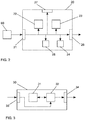
- Fig. 2 shows a simplified schematic representation of a first embodiment of a device 20 for setting a head-up display in a motor vehicle.
- the device 20 has an input 21, via which, for example, data of an adjustment device 60, which has at least one camera and a projection unit, can be received.
- a control unit 22 ensures that the setting device 60 is brought into a defined position in the motor vehicle, preferably into the position of an eyebox of the head-up display.
- the adjusting device can be fastened, for example, by means of a holder to bearings in at least one sun visor of the motor vehicle.
- the control unit 22 also controls the projection of an alignment pattern with the projection unit onto a calibration panel positioned outside the motor vehicle.
- the projection unit can have a laser, for example.
- the alignment pattern can be a line in this case.
- a computing unit 23 detects the calibration table and the alignment pattern with a calibrated camera installed in the motor vehicle. In addition, the computing unit 23 determines a deviation of the setting device from the defined position in the motor vehicle on the basis of the image data of the calibrated camera. The computing unit 23 likewise captures at least one test image represented by the head-up display with the camera of the setting device 60 and determines setting information for the head-up display on the basis of the at least one captured test image. Of course, separate units can also be provided for the different functions of the computing unit 23.
- the setting information is output to a control device for the head-up display or provided for an adjustment of the head-up display via an output 26 of the device 20.
- the control unit 22 and the computing unit 23 can be controlled by a control unit 24.
- Settings of the control unit 22, the computing unit 23 or the control unit 24 can optionally be changed via a user interface 27.
- the data accumulating in the device 20 can, if required, be stored in a memory 25 of the device 20, for example for later evaluation or for use by the components of the device 20.
- the control unit 22, the computing unit 23 and the control unit 24 can be dedicated Hardware can be implemented, for example as integrated circuits. Of course, they can also be partially or completely combined or implemented as software that runs on a suitable processor, for example on a GPU or a CPU.
- the input 21 and the output 26 can be implemented as separate interfaces or as a combined bidirectional interface.
- the device 20 is an independent component. However, it can also be integrated in the setting device 60.
- Fig. 3 shows a simplified schematic representation of a second embodiment of a device 30 for setting a head-up display in a motor vehicle.
- the device 30 has a processor 32 and a memory 31.
- device 30 is a computer or a control device. Instructions are stored in the memory 31 which, when executed by the processor 32, cause the device 30 to carry out the steps in accordance with one of the described methods.
- the instructions stored in the memory 31 thus embody a program which can be executed by the processor 32 and which implements the method according to the invention.
- the device 30 has an input 33 for receiving information, for example data from a setting device. Data generated by processor 32 are provided via an output 34. In addition, they can be stored in the memory 31.
- the input 33 and the output 34 can be combined to form a bidirectional interface.
- Processor 32 may include one or more processor units, such as microprocessors, digital signal processors, or combinations thereof.
- the memories 25, 31 of the described embodiments can have both volatile and non-volatile memory areas and comprise a wide variety of storage devices and storage media, for example hard disks, optical storage media or semiconductor memories.
- Fig. 4 schematically shows a head-up display 51 for a motor vehicle 50.
- contents can be displayed on a projection surface 42 of the motor vehicle 50, for example on the windscreen.
- the displayed contents are generated by an imaging unit 40 and projected onto the projection surface 42 with the aid of an optical module 41.
- the projection takes place in an area of the windshield above the steering wheel.
- the imaging unit 40 can be, for example, an LCD TFT display.
- the head-up display 51 is usually installed in a dashboard of the motor vehicle 50. The position of the head-up display 51 can be adjusted by means of adjusting elements 43.
- Fig. 5 schematically shows a motor vehicle 50 with a head-up display 51.
- the head-up display 51 is controlled by an associated control unit 52.
- Further components of motor vehicle 50 are a camera 53 for environmental monitoring, a navigation system 54, a data transmission unit 55 and a number of Assistance systems 56, one of which is shown as an example.
- a connection to service providers can be established by means of the data transmission unit 55, for example for calling up card data.
- a memory 57 is provided for storing data.
- the data exchange between the various components of motor vehicle 50 takes place via a network 58.
- Fig. 6 schematically shows an adjustment device 60 for use in the method Fig. 1 or with the device FIG. 2 or FIG. 3 .
- the setting device 60 has a projection unit 62 for projecting an alignment pattern onto a calibration panel positioned outside a motor vehicle.
- the projection unit 62 can have a laser, for example.
- the alignment pattern can be a line in this case.
- a camera 61 is used to capture at least one test image generated by a head-up display of the motor vehicle.
- the adjusting device 60 can be fastened in a defined position in the motor vehicle with a holder 63.
- at least one manipulator 64 is provided, for example a screwdriver, with which the head-up display can be adjusted. This can be attached to the setting device 60 or can only be controlled by the setting device 60.
- the adjusting device 60 can have two cameras 61 for motor vehicles with left-hand drive and motor vehicles with right-hand drive.
- two projection units 62 can also be provided.
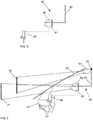
- Fig. 7 shows schematically the use of the adjusting device 60 Fig. 6 for setting a head-up display 51 in a motor vehicle.
- the operator who moves the vehicle to the test stand, positions the adjusting device 60 on bearings 65 of the sun visors, for example on the central bearings. Then he starts the setting process.
- This can be implemented both on the system and by means of a series test system.
- the control of the cameras 53, 61 and the projection unit 62 and the display of the test images is now carried out automatically via the system or the series test system.
- the projection unit 62 has a laser.
- the camera 61 of the setting device 60 and the laser were optimally aligned with one another in advance in an alignment process.
- the laser now projects a line onto a calibration board 70, which is located in front of the vehicle.
- a previously calibrated multifunction camera 53 of the vehicle determines the rotational deviations of the projected line around all axes from the desired position with the holder 63 of the setting device 60 in an ideal position.
- a shift of the laser line along the Y axis (left-right) means that the holder 63 is rotated the vertical axis (Z axis).
- a shift of the laser line along the Z-axis (top-bottom) means a rotation of the holder 63 about the horizontal axis (Y-axis).
- a rotation of the laser line clockwise or counterclockwise means a rotation of the holder 63 about the vehicle longitudinal axis (X axis). Since the laser and the calibration camera 61 are aligned with one another, the viewing direction of the calibration camera 61 is now known and the camera 61 is ready for use in the calibration.
- the camera 61 now determines the deviation of the head-up display 51 using the projection surface 42, i.e. the windshield, generated virtual image 71 of the target position with an ideally installed head-up display module, taking into account the deviations determined by the multifunction camera 53.
- the setting information determined from these deviations can now be written into the control unit of the head-up display 51 and taken into account in the display.
- automated manipulators 64 can be controlled which change the position of the head-up display module by means of the setting elements 43 such that the image is set to a zero position.
- instructions can be issued as to how many revolutions and in which direction of rotation the adjusting elements have to be adjusted in order to set the image to the zero position. A guided adjustment is thus carried out. After completion of the adjustment process, the operator removes the adjustment device 60 from the vehicle before moving out of the test bench and then moves the vehicle out of the test bench.
- the guided adjustment described above can also be carried out by a customer service when the head-up display 51 is set.
Abstract
Description
- Die vorliegende Erfindung betrifft ein Verfahren, eine Vorrichtung und ein computerlesbares Speichermedium mit Instruktionen zum Einstellen eines Head-Up-Displays in einem Kraftfahrzeug. Die Erfindung betrifft weiterhin eine Einstellvorrichtung zur Verwendung in einem solchen Verfahren oder mit einer solchen Vorrichtung.
- Die Fahrzeugnavigation wird in Zukunft vermehrt Darstellungen in einem Head-Up-Display (HUD) nutzen. Dabei werden die Lichtstrahlen eines im Armaturenbrett verbauten Displays über mehrere Spiegel und Linsen gefaltet und über eine Projektionsfläche in das Auge des Fahrers gespiegelt, sodass dieser ein virtuelles Bild außerhalb des Fahrzeugs wahrnimmt. Als Projektionsfläche dient im Automobilbereich oftmals die Frontscheibe, deren gekrümmte Form bei der Darstellung berücksichtigt werden muss. Als Alternative wird zum Teil auch eine zusätzliche Scheibe aus Glas oder Kunststoff genutzt, die zwischen dem Fahrer und der Frontscheibe auf dem Armaturenbrett angeordnet ist. Durch die optische Überlagerung von Anzeige und Fahrszene sind weniger Kopf- und Augenbewegungen zum Ablesen der Informationen notwendig. Zudem verringert sich der Adaptationsaufwand für die Augen, da abhängig von der virtuellen Distanz der Anzeige weniger bis gar nicht akkommodiert werden muss. Aktuelle Serien-HUDs beschränken sich jedoch auf Anzeigen direkt unter dem primären Sichtbereich des Fahrers. Diese Anzeigetechnologie reduziert zwar Blickabwendungen von der Straße, hat aber weiterhin den Nachteil, dass die präsentierten Informationen interpretiert und auf die reale Situation übertragen werden müssen, da sie nicht in der realen Szene registriert sind. Dies kann in komplexen Situationen einen mental beanspruchenden kognitiven Prozess darstellen.
- Mit der stetigen Weiterentwicklung von Virtual- und Augmented-Reality-Technologien und -Anwendungen finden diese auch Einzug in das Automobil, insbesondere für die Anzeigen von Head-Up-Displays. Bei Augmented Reality (AR), auf Deutsch "erweiterte Realität", handelt es sich um die Anreicherung der realen Welt durch virtuelle Elemente, die im dreidimensionalen Raum ortskorrekt registriert sind und eine Echtzeitinteraktion erlauben. Da sich in der Fachwelt im deutschsprachigen Raum der Ausdruck "Augmented Reality" gegenüber dem Ausdruck "erweiterte Realität" durchgesetzt hat, wird im Folgenden ersterer benutzt. Synonym wird auch der Ausdruck "Mixed Reality" verwendet.
- Durch Markieren von Objekten und Einblenden von Informationen an ihrem realen Bezugsort, d.h. durch eine kontaktanaloge Darstellung, lassen sich umweltbezogene Informationen im Sichtfeld des Fahrers direkt darstellen. Diese direkte grafische Anreicherung der Umwelt in Form von Augmented Reality kann die kognitiven Transferanforderungen erheblich reduzieren. Augmented Reality bietet vielfältige Anwendungsmöglichkeiten zur Unterstützung des Fahrers durch kontaktanaloge Markierung von Fahrbahnen und Objekten, insbesondere für die Fahrzeugnavigation.
- Damit die Funktionalität eines Head-Up-Displays, also das Darstellen von Fahrinformationen auf der Frontscheibe, vom Kunden als korrekt empfunden wird, erfordert der Verbau von Head-Up-Displays aufgrund der auftretenden Toleranzen eine Kalibrierung während der Fahrzeugproduktion. Die Toleranzen entstehen durch den Aufbau des Head-Up-Display-Moduls, d.h. des Projektors, der das darzustellende Bild über mehrere Umlenkspiegel auf die Frontscheibe projiziert, den Einbau des Moduls ins Cockpit sowie durch den Aufbau und den Einbau der Frontscheibe. Sofern Augmented-Reality-Darstellungen genutzt werden, sind die zulässigen Toleranzen noch enger. In diesem Fall ist neben der Kalibrierung, also dem softwareseitigen Ausgleichen der Toleranzen durch Offsets im zugehörigen Steuergerät, auch noch eine Justage der Einbaulage des Moduls relativ zur Frontscheibe erforderlich.
- In diesem Zusammenhang beschreibt
DE 10 2005 037 797 B4 ein System zur Kalibrierung einer Projektion eines Head-Up-Displays, das automatisierbar bei der Fertigung eines Transportmittels oder einer Nachrüstung verwendbar ist. Eine Projektionsvorrichtung erzeugt ein Kalibriermuster auf einer Projektionsfläche, das von einer Kameravorrichtung aufgenommen wird. Die Projektionsvorrichtung und die Kameravorrichtung werden von einer Steuereinheit angesteuert. Zusätzlich umfasst das System ein Mittel zur automatischen Kalibrierung der Projektion sowie ein von der Steuereinheit ansteuerbares Positioniermittel für die Kameravorrichtung. In Abhängigkeit von den von der Kameravorrichtung erfassten Signalen des Kalibriermusters steuert die Steuereinheit das Mittel zur automatischen Einstellung der Kalibrierung so an, dass eine vorbestimmte Zielfunktion, insbesondere die Verzerrungsfreiheit der Projektion erfüllt wird. Die Projektion kann auch auf ein Kalibriertarget erfolgen. -
DE 10 2012 010 120 A1 beschreibt ein Verfahren zur Kalibrierung eines Head-Up-Displays in einem Kraftfahrzeug. Bei dem Verfahren wird eine Kamera in einer definierten Position in dem Fahrzeug positioniert. Das Head-Up-Display projiziert dann ein Testbild auf eine Windschutzscheibe des Fahrzeugs. Die Kamera ist so positioniert, dass von der Kamera wenigstens ein Kantenbereich einer Eyebox aufgenommen wird. -
DE 10 2014 013 221 A1 beschreibt eine Vorrichtung zur Kalibrierung einer Bildanzeigeeinheit eines Fahrzeugs. Die Vorrichtung umfasst eine der Bildanzeigeeinheit zugehörige Projektionseinheit, die Bilder auf einen Projektionsschirm in ein Sichtfeld eines Fahrzeuginsassen und auf eine an einem Fahrzeugsitz angeordnete Kopfstütze projiziert. Mittels der Projektionseinheit wird ein Testmuster unmittelbar auf eine Oberfläche der Kopfstütze projiziert und von einer Erfassungseinheit erfasst. Für die Projektion des Testmusters kann die Projektionseinheit einen gesonderten Laser umfassen. Mittels einer Auswerteeinheit erfolgt ein Vergleich des erfassten Testmusters mit einem Sollmuster. Als Erfassungseinheit kann eine Innenraumkamera genutzt werden. - Die Kalibrierung erfolgt aktuell in der Regel auf einem Prüfstand für Fahrerassistenzsysteme am Ende des Produktionsbandes. Auf dem Prüfstand wird, nachdem das Fahrzeug im Prüfstand ausgerichtet wurde, eine Kamera mittels eines mechanisch verfahrbaren Teleskop-Arms auf die wahrscheinlichste Augenposition des Fahrers gebracht, d.h. die Mitte der sogenannten Eyebox. Diese Position wird anhand eines simulierten idealen Fahrzeugs vorgegeben. Etwaige Abweichungen des realen Fahrzeugs bezüglich der Position im Prüfstand und im Raum werden durch Lasersensoren mittels einer Erfassung der Radhauskanten ermittelt und bei der Positionierung der Kamera berücksichtigt. Im Anschluss werden verschiedene Testbilder angezeigt, anhand derer zum einen die Lage des dargestellten Bildes als auch die Verzerrung und Bildfehler der Darstellung ermittelt werden. Diese Informationen werden dann in das entsprechende Steuergerät geschrieben, welches diese Abweichungen daraufhin bei der Darstellung der Fahrinformationen berücksichtigt.
- Allerdings sind die Schwankungen beim Aufbau der Radhauskanten groß, sodass bei der Positionierung schon Fehler entstehen können. Gleichzeitig sind diese Punkte die einzigen von außen messbaren Konturen, die durch Laser erfasst und mit der Simulation verglichen werden können.
- Um die Toleranzen bei der Positionierung der Kamera zu umgehen, kann die Justage und Kalibrierung bereits in der Montagelinie erfolgen. Hierbei wird ein Teleskop-Arm mit einer Kamera mithilfe eines Manipulators ins Fahrzeug eingebracht. Dieser Manipulator kann sich bei noch nicht eingebauten Sitzen auf Löchern eines Referenzpunktsystems im Boden abstützen und dann die Kamera in der Mitte der Eyebox positionieren. Im Anschluss verfahren Schrauber automatisiert zu den Einstellschrauben des Moduls. Danach werden die dargestellten Testbilder mithilfe der Kamera ausgewertet und die Schrauber entsprechend angesteuert, um das Bild in eine optimale Lage zu bringen. Abschließend werden kleine Verzerrungen im Bild über eine Kalibrierung ausgeglichen.
- Allerdings ist auch dieser Prozess nicht produktionssicher, da die Schwingungen in der Montagelinie zu Fehlern bei der Bildaufnahme führen können. Dies kann wiederrum die Auswertung unmöglich machen.
- Ferner gibt es bei beiden Lösungen keine ausreichende Kundendienstlösung. Aktuell wird mit Hilfe einer Sonnenblende mit Schlitz das Bild von einem Kundendienstmitarbeiter in eine plausible Position gebracht. Bildfehler oder Verzerrungen werden hierbei nicht betrachtet. Auch die hohen Anforderungen an die Genauigkeit für Augmented-Reality-Darstellungen können durch diese Methode nur schwer eingehalten werden.
- Es ist eine Aufgabe der Erfindung, ein verbessertes Konzept zum Einstellen eines Head-Up-Displays in einem Kraftfahrzeug bereitzustellen.
- Diese Aufgabe wird durch ein Verfahren mit den Merkmalen des Anspruchs 1, durch eine Vorrichtung mit den Merkmalen des Anspruchs 6, durch ein computerlesbares Speichermedium mit Instruktionen gemäß Anspruch 7 und durch eine Einstellvorrichtung mit den Merkmalen des Anspruchs 8 gelöst. Bevorzugte Ausgestaltungen der Erfindung sind Gegenstand der abhängigen Ansprüche.
- Gemäß einem ersten Aspekt der Erfindung umfasst ein Verfahren zum Einstellen eines Head-Up-Displays in einem Kraftfahrzeug die Schritte:
- Einbringen einer Einstellvorrichtung in eine definierte Position im Kraftfahrzeug, wobei die Einstellvorrichtung zumindest eine Kamera und eine Projektionseinheit aufweist;
- Projizieren eines Ausrichtungsmusters mit der Projektionseinheit auf eine außerhalb des Kraftfahrzeugs positionierte Kalibriertafel;
- Erfassen der Kalibriertafel und des Ausrichtungsmusters mit einer im Kraftfahrzeug verbauten kalibrierten Kamera;
- Bestimmen einer Abweichung der Einstellvorrichtung von der definierten Position im Kraftfahrzeug auf Basis der Bilddaten der kalibrierten Kamera;
- Erfassen zumindest eines durch das Head-Up-Display dargestellten Testbildes mit der Kamera der Einstellvorrichtung; und
- Ermitteln von Einstellinformationen für das Head-Up-Display auf Basis des zumindest einen erfassten Testbildes.
- Gemäß einem weiteren Aspekt der Erfindung enthält ein computerlesbares Speichermedium Instruktionen, die bei Ausführung durch einen Computer den Computer zur Ausführung der folgende Schritte zum Einstellen eines Head-Up-Displays in einem Kraftfahrzeug veranlassen:
- Einbringen einer Einstellvorrichtung in eine definierte Position im Kraftfahrzeug, wobei die Einstellvorrichtung zumindest eine Kamera und eine Projektionseinheit aufweist;
- Projizieren eines Ausrichtungsmusters mit der Projektionseinheit auf eine außerhalb des Kraftfahrzeugs positionierte Kalibriertafel;
- Erfassen der Kalibriertafel und des Ausrichtungsmusters mit einer im Kraftfahrzeug verbauten kalibrierten Kamera;
- Bestimmen einer Abweichung der Einstellvorrichtung von der definierten Position im Kraftfahrzeug auf Basis der Bilddaten der kalibrierten Kamera;
- Erfassen zumindest eines durch das Head-Up-Display dargestellten Testbildes mit der Kamera der Einstellvorrichtung; und
- Ermitteln von Einstellinformationen für das Head-Up-Display auf Basis des zumindest einen erfassten Testbildes.
- Der Begriff Computer ist dabei breit zu verstehen. Insbesondere umfasst er auch Workstations, Steuergeräte und andere prozessorbasierte Datenverarbeitungsvorrichtungen.
- Gemäß einem weiteren Aspekt der Erfindung weist eine Vorrichtung zum Einstellen eines Head-Up-Displays in einem Kraftfahrzeug auf:
- eine Steuerungseinheit zum Einbringen einer Einstellvorrichtung in eine definierte Position im Kraftfahrzeug, wobei die Einstellvorrichtung zumindest eine Kamera und eine Projektionseinheit aufweist, und zum Projizieren eines Ausrichtungsmusters mit der Projektionseinheit auf eine außerhalb des Kraftfahrzeugs positionierte Kalibriertafel; und
- eine Recheneinheit zum Erfassen der Kalibriertafel und des Ausrichtungsmusters mit einer im Kraftfahrzeug verbauten kalibrierten Kamera, zum Bestimmen einer Abweichung der Einstellvorrichtung von der definierten Position im Kraftfahrzeug auf Basis der Bilddaten der kalibrierten Kamera, zum Erfassen zumindest eines durch das Head-Up-Display dargestellten Testbildes mit der Kamera der Einstellvorrichtung, und zum Ermitteln von Einstellinformationen für das Head-Up-Display auf Basis des zumindest einen erfassten Testbildes.
- Gemäß einem weiteren Aspekt der Erfindung weist eine Einstellvorrichtung zur Verwendung in einem erfindungsgemäßen Verfahren oder mit einer erfindungsgemäßen Vorrichtung auf:
- eine Projektionseinheit zum Projizieren eines Ausrichtungsmusters auf eine außerhalb des Kraftfahrzeugs positionierte Kalibriertafel;
- eine Kamera zum Erfassen zumindest eines durch das Head-Up-Display dargestellten Testbildes; und
- eine Halterung zum Befestigen der Einstellvorrichtung in einer definierten Position im Kraftfahrzeug.
- Die erfindungsgemäße Lösung basiert auf der Idee, die Ausrichtung der Kamera, die die Testbilder aufnimmt, auf Basis einer im Fahrzeug verbauten Multifunktionskamera umzusetzen. In Fahrzeugen mit Head-Up-Display ist eine Multifunktionskamera verbaut. Diese erfasst wichtige Fahrinformationen, wie z.B. Verkehrsschilder oder Fahrbahnmarkierungen, und gibt diese an das Head-Up-Display zur Darstellung auf der Scheibe weiter. Für die Kalibrierung der Multifunktionskamera wird aktuell eine Kalibriertafel verwendet, auf der ein Muster abgebildet ist. Beispielsweise hat die Kalibriertafel eine Größe von 1500mmx2000mm und befindet sich in einer Entfernung von 1m vor dem Fahrzeug. Die Multifunktionskamera nimmt das Muster auf und kalibriert sich auf Basis des aufgenommenen Musters. Die Kalibriertafel ist in der Regel auch bei der Kalibrierung des Head-Up-Displays in der Kalibrierposition, d.h. bis fast auf den Boden heruntergefahren, damit die Bremslichter der vorherigen Fahrzeuge die Bildaufnahme der Testbilder nicht behindern.
- Die Einstellvorrichtung besteht nun aus der Kamera zur Aufnahme der Testbilder, einer Projektionseinheit, die fest relativ zur Kamera angeordnet ist, und einer Halterung, an der die Kamera und die Projektionseinheit angebracht sind. Der Ablauf der Justage bzw. Kalibrierung erfolgt in mehreren Schritten. Zunächst wird die Halterung in das Fahrzeug eingebracht und fixiert. Die Position der Kamera stimmt nun bereits annähernd, da die Halterung vorzugsweise so konstruiert ist, dass die Kamera in der Nähe der Mitte der Eyebox positioniert ist. Nun wird die Projektionseinheit aktiviert und projiziert ein Ausrichtungsmuster auf die Kalibriertafel. Dieses Ausrichtungsmuster wird von der Multifunktionskamera erfasst. Die Abweichungen zur Ideallage des Ausrichtungsmusters werden an die Kamera der Einstellvorrichtung übertragen bzw. bei der späteren Auswertung der Testbilder berücksichtigt. Die Ideallage wird hierbei beispielsweise im Rahmen der Entwicklung bei dem simulierten Fahrzeug ermittelt und in der Multifunktionskamera hinterlegt. Da die Multifunktionskamera zuvor bereits kalibriert wurde, kann sie die Abweichungen des Ausrichtungsmusters von der Ideallage bestimmen.
- Wurde durch die Kalibrierung der Multifunktionskamera beispielsweise eine Verbautoleranz der Multifunktionskamera von 1° Gierwinkel (links-rechts) ermittelt und misst die Multifunktionskamera das Ausrichtungsmuster nun 2° gierend neben der Ideallage, so überträgt sie unter Berücksichtigung der Kalibrierergebnisse nun eine Abweichung von 1° Gierwinkel an die Kamera der Einstellvorrichtung.
- Anhand der durch die Multifunktionskamera gemessenen Abweichungen liegt der Kamera der Einstellvorrichtung somit die Information vor, wie sie relativ zur Ideallage positioniert ist. Dies kann nun bei der Bildaufnahme der Testbilder bzw. dem Ermitteln der Einstellinformationen für das Head-Up-Display berücksichtigt werden.
- Die beschriebene Lösung hat eine Reihe von Vorteilen. Aufgrund der inhärenten Wiederholgenauigkeit ist sie prozesssicher. Zudem reduziert sie die benötigte Fertigungszeit, da die Positionierung der Kamera bzw. der Kalibiervorrichtung schneller abgeschlossen werden kann. Des Weiteren sind die Kosten niedriger als bei Lösungen, die auf einem mechanisch verfahrbaren Teleskop-Arm beruhen. Gleichzeitig werden hohe Genauigkeiten erreicht. Die beschriebene Lösung ist zudem einheitlich sowohl in der Produktion als auch beim Kundendienst nutzbar.
- Gemäß einem Aspekt der Erfindung werden die Einstellinformationen für das Head-Up-Display an ein Steuergerät für das Head-Up-Display übermittelt. Alternativ wird das Head-Up-Display auf Basis der Einstellinformationen justiert. Anhand der Einstellinformationen können einerseits die ermittelten Abweichungen in das Steuergerät des Head-Up-Displays geschrieben werden, d.h. das Head-Up-Display wird kalibriert. Dies ist insbesondere bei lediglich kleinen Abweichungen sinnvoll, da auf eine zusätzliche Justage verzichtet werden kann. Alternativ kann die Position des Head-Up-Display-Moduls optimiert werden, d.h. es wird eine Justage durchgeführt. Dies ist insbesondere bei größeren Abweichungen sinnvoll, da so der vollständige Darstellungsbereich des Head-Up-Displays genutzt werden kann.
- Gemäß einem Aspekt der Erfindung weist die Projektionseinheit einen Laser auf. Das Ausrichtungsmuster ist dabei vorzugsweise eine Linie. Die Verwendung eines Lasers hat den Vorteil, dass ein sehr genau definiertes Ausrichtungsmuster projiziert werden kann, insbesondere in Anbetracht des Abstandes zwischen der Projektionseinheit und der Kalibiertafel. Eine Linie stellt dabei ein besonders leicht zu erzeugendes Ausrichtungsmuster dar, das eine lediglich eindimensionale Ablenkung des generierten Laserstrahls benötigt.
- Gemäß einem Aspekt der Erfindung wird die Einstellvorrichtung mittels einer Halterung an Lagern zumindest einer Sonnenblende des Kraftfahrzeugs befestigt, beispielsweise an den Mittellagern der Sonnenblenden. Dies hat den Vorteil, dass die Einstellvorrichtung einfach eingehakt und fixiert werden kann. Zudem befinden sich die Lager an einer definierten Position im Kraftfahrzeug, so dass eine sehr gut reproduzierbare Positionierung der Einstellvorrichtung gewährleistet ist.
- Gemäß einem Aspekt der Erfindung ist die definierte Position im Kraftfahrzeug die Position einer Eyebox des Head-Up-Displays. Da die vom Head-Up-Display generierten Inhalte im Bereich der Eyebox sichtbar sein sollen ist es zweckmäßig, auch die Einstellvorrichtung bzw. die Kamera der Einstellvorrichtung in diesem Bereich zu positionieren.
- Gemäß einem Aspekt der Erfindung weist die Einstellvorrichtung einen Manipulator zum Justieren des Head-Up-Displays auf, beispielsweise einen Schrauber. Dies hat den Vorteil, dass die Einstellvorrichtung nicht nur die Einstellinformationen für das Head-Up-Display bestimmt, sondern auf Basis der Einstellinformationen auch gleich eine Justage des Head-Up-Display-Moduls vornimmt. Zwar erhöht die Verwendung von automatisierten Manipulatoren das Gewicht der Einstellvorrichtung, was die Ergonomie des Arbeitsablaufs des Bedieners beeinflusst, dafür kann auf einen separaten Justageschritt, der eventuell einer weiteren Kontrolle bedarf, verzichtet werden.
- Gemäß einem Aspekt der Erfindung weist die Einstellvorrichtung zwei Kameras für Kraftfahrzeuge mit Linkslenkung und Kraftfahrzeuge mit Rechtslenkung auf. Neben einer Ausführungsform, bei der die Einstellvorrichtung entweder für Linkslenker oder Rechtslenker ausgelegt ist, kann die Einstellvorrichtung zwei Kameras und gegebenenfalls zwei Projektionseinheiten für Links- und Rechtslenker aufweisen. Auf diese Weise kann die Einstellvorrichtung für beide Arten von Fahrzeugen genutzt werden, so dass nicht unterschiedliche Einstellvorrichtungen bereitgehalten werden müssen.
- Weitere Merkmale der vorliegenden Erfindung werden aus der nachfolgenden Beschreibung und den angehängten Ansprüchen in Verbindung mit den Figuren ersichtlich.
- Fig. 1
- zeigt schematisch ein Verfahren zum Einstellen eines Head-Up-Displays in einem Kraftfahrzeug;
- Fig. 2
- zeigt eine erste Ausführungsform einer Vorrichtung zum Einstellen eines Head-Up-Displays in einem Kraftfahrzeug;
- Fig. 3
- zeigt eine zweite Ausführungsform einer Vorrichtung zum Einstellen eines Head-Up-Displays in einem Kraftfahrzeug;
- Fig. 4
- zeigt schematisch einen allgemeinen Aufbau einer Head-Up-Display-Vorrichtung für ein Kraftfahrzeug;
- Fig. 5
- stellt schematisch ein Kraftfahrzeug mit einer Head-Up-Display-Vorrichtung dar;
- Fig. 6
- zeigt schematisch eine Einstellvorrichtung; und
- Fig. 7
- zeigt schematisch die Verwendung der Einstellvorrichtung aus
Fig. 6 zum Einstellen eines Head-Up-Displays in einem Kraftfahrzeug. - Zum besseren Verständnis der Prinzipien der vorliegenden Erfindung werden nachfolgend Ausführungsformen der Erfindung anhand der Figuren detaillierter erläutert. Es versteht sich, dass sich die Erfindung nicht auf diese Ausführungsformen beschränkt und dass die beschriebenen Merkmale auch kombiniert oder modifiziert werden können, ohne den Schutzbereich der Erfindung zu verlassen, wie er in den angehängten Ansprüchen definiert ist.
-
Fig. 1 zeigt schematisch ein Verfahren zum Einstellen eines Head-Up-Displays in einem Kraftfahrzeug. In einem ersten Schritt 10 wird eine Einstellvorrichtung in eine definierte Position im Kraftfahrzeug eingebracht, vorzugsweise in die Position einer Eyebox des Head-Up-Displays. Die Einstellvorrichtung kann beispielsweise mittels einer Halterung an Lagern zumindest einer Sonnenblende des Kraftfahrzeugs befestigt werden. Die Einstellvorrichtung weist zumindest eine Kamera und eine Projektionseinheit auf. Anschließend wird mit der Projektionseinheit ein Ausrichtungsmuster auf eine außerhalb des Kraftfahrzeugs positionierte Kalibriertafel projiziert 11. Die Projektionseinheit kann z.B. einen Laser aufweisen. Das Ausrichtungsmuster kann in diesem Fall eine Linie sein. Mit einer im Kraftfahrzeug verbauten kalibrierten Kamera werden die Kalibriertafel und das Ausrichtungsmuster erfasst 12. Auf Basis der Bilddaten der kalibrierten Kamera wird dann eine Abweichung der Einstellvorrichtung von der definierten Position im Kraftfahrzeug bestimmt 13. Daraufhin wird zumindest ein durch das Head-Up-Display dargestelltes Testbild mit der Kamera der Einstellvorrichtung erfasst 14. Auf Basis des zumindest einen erfassten Testbildes werden schließlich Einstellinformationen für das Head-Up-Display ermittelt 15. -
Fig. 2 zeigt eine vereinfachte schematische Darstellung einer ersten Ausführungsform einer Vorrichtung 20 zum Einstellen eines Head-Up-Displays in einem Kraftfahrzeug. Die Vorrichtung 20 hat einen Eingang 21, über den beispielsweise Daten einer Einstellvorrichtung 60, die zumindest eine Kamera und eine Projektionseinheit aufweist, empfangen werden können. Eine Steuerungseinheit 22 sorgt dafür, dass die Einstellvorrichtung 60 in eine definierte Position im Kraftfahrzeug eingebracht wird, vorzugsweise in die Position einer Eyebox des Head-Up-Displays. Die Einstellvorrichtung kann beispielsweise mittels einer Halterung an Lagern zumindest einer Sonnenblende des Kraftfahrzeugs befestigt werden. Die Steuerungseinheit 22 steuert zudem das Projizieren eines Ausrichtungsmusters mit der Projektionseinheit auf eine außerhalb des Kraftfahrzeugs positionierte Kalibriertafel. Die Projektionseinheit kann z.B. einen Laser aufweisen. Das Ausrichtungsmuster kann in diesem Fall eine Linie sein. Eine Recheneinheit 23 erfasst die Kalibriertafel und das Ausrichtungsmuster mit einer im Kraftfahrzeug verbauten kalibrierten Kamera. Zudem bestimmt die Recheneinheit 23 eine Abweichung der Einstellvorrichtung von der definierten Position im Kraftfahrzeug auf Basis der Bilddaten der kalibrierten Kamera. Ebenso erfasst die Recheneinheit 23 zumindest ein durch das Head-Up-Display dargestellte Testbild mit der Kamera der Einstellvorrichtung 60 und ermittelt Einstellinformationen für das Head-Up-Display auf Basis des zumindest einen erfassten Testbildes. Natürlich können für die verschiedenen Funktionen der Recheneinheit 23 auch getrennte Einheiten vorgesehen sein. Über einen Ausgang 26 der Vorrichtung 20 werden die Einstellinformationen an ein Steuergerät für das Head-Up-Display ausgegeben oder für eine Justage des Head-Up-Displays bereitgestellt. - Die Steuerungseinheit 22 und die Recheneinheit 23 können von einer Kontrolleinheit 24 gesteuert werden. Über eine Benutzerschnittstelle 27 können gegebenenfalls Einstellungen der Steuerungseinheit 22, der Recheneinheit 23 oder der Kontrolleinheit 24 geändert werden. Die in der Vorrichtung 20 anfallenden Daten können bei Bedarf in einem Speicher 25 der Vorrichtung 20 abgelegt werden, beispielsweise für eine spätere Auswertung oder für eine Nutzung durch die Komponenten der Vorrichtung 20. Die Steuerungseinheit 22, die Recheneinheit 23 sowie die Kontrolleinheit 24 können als dedizierte Hardware realisiert sein, beispielsweise als integrierte Schaltungen. Natürlich können sie aber auch teilweise oder vollständig kombiniert oder als Software implementiert werden, die auf einem geeigneten Prozessor läuft, beispielsweise auf einer GPU oder einer CPU. Der Eingang 21 und der Ausgang 26 können als getrennte Schnittstellen oder als eine kombinierte bidirektionale Schnittstelle implementiert sein. Im beschriebenen Beispiel ist die Vorrichtung 20 eine eigenständige Komponente. Sie kann aber ebenso in der Einstellvorrichtung 60 integriert sein.
-
Fig. 3 zeigt eine vereinfachte schematische Darstellung einer zweiten Ausführungsform einer Vorrichtung 30 zum Einstellen eines Head-Up-Displays in einem Kraftfahrzeug. Die Vorrichtung 30 weist einen Prozessor 32 und einen Speicher 31 auf. Beispielsweise handelt es sich bei der Vorrichtung 30 um einen Computer oder ein Steuergerät. Im Speicher 31 sind Instruktionen abgelegt, die die Vorrichtung 30 bei Ausführung durch den Prozessor 32 veranlassen, die Schritte gemäß einem der beschriebenen Verfahren auszuführen. Die im Speicher 31 abgelegten Instruktionen verkörpern somit ein durch den Prozessor 32 ausführbares Programm, welches das erfindungsgemäße Verfahren realisiert. Die Vorrichtung 30 hat einen Eingang 33 zum Empfangen von Informationen, beispielsweise von Daten einer Einstellvorrichtung. Vom Prozessor 32 generierte Daten werden über einen Ausgang 34 bereitgestellt. Darüber hinaus können sie im Speicher 31 abgelegt werden. Der Eingang 33 und der Ausgang 34 können zu einer bidirektionalen Schnittstelle zusammengefasst sein. - Der Prozessor 32 kann eine oder mehrere Prozessoreinheiten umfassen, beispielsweise Mikroprozessoren, digitale Signalprozessoren oder Kombinationen daraus.
- Die Speicher 25, 31 der beschriebenen Ausführungsformen können sowohl volatile als auch nichtvolatile Speicherbereiche aufweisen und unterschiedlichste Speichergeräte und Speichermedien umfassen, beispielsweise Festplatten, optische Speichermedien oder Halbleiterspeicher.
-
Fig. 4 zeigt schematisch ein Head-Up-Display 51 für ein Kraftfahrzeug 50. Mit Hilfe des Head-Up-Displays 51 können Inhalte auf einer Projektionsfläche 42 des Kraftfahrzeugs 50 angezeigt werden, beispielsweise auf der Frontscheibe. Die dargestellten Inhalte werden durch eine bildgebende Einheit 40 erzeugt und mit Hilfe eines optischen Moduls 41 auf die Projektionsfläche 42 projiziert. Typischerweise erfolgt die Projektion dabei in einen Bereich der Frontscheibe oberhalb des Lenkrades. Die bildgebende Einheit 40 kann beispielsweise ein LCD-TFT-Display sein. Das Head-Up-Display 51 ist in der Regel in einem Armaturenbrett des Kraftfahrzeugs 50 verbaut. Mittels Einstellelementen 43 kann die Position des Head-Up-Displays 51 justiert werden. -
Fig. 5 stellt schematisch ein Kraftfahrzeug 50 mit einem Head-Up-Display 51 dar. Das Head-Up-Display 51 wird von einem zugehörigen Steuergerät 52 gesteuert. Weitere Komponenten des Kraftfahrzeugs 50 sind eine Kamera 53 für die Umfeldüberwachung, ein Navigationssystem 54, eine Datenübertragungseinheit 55 sowie eine Reihe von Assistenzsystemen 56, von denen eines exemplarisch dargestellt ist. Mittels der Datenübertragungseinheit 55 kann eine Verbindung zu Dienstanbietern aufgebaut werden, beispielsweise zum Abrufen von Kartendaten. Zur Speicherung von Daten ist ein Speicher 57 vorhanden. Der Datenaustausch zwischen den verschiedenen Komponenten des Kraftfahrzeugs 50 erfolgt über ein Netzwerk 58. -
Fig. 6 zeigt schematisch eine Einstellvorrichtung 60 zur Verwendung in dem Verfahren ausFig. 1 oder mit der Vorrichtung ausFig. 2 oder Fig. 3 . Die Einstellvorrichtung 60 hat eine Projektionseinheit 62 zum Projizieren eines Ausrichtungsmusters auf eine außerhalb eines Kraftfahrzeugs positionierte Kalibriertafel. Die Projektionseinheit 62 kann z.B. einen Laser aufweisen. Das Ausrichtungsmuster kann in diesem Fall eine Linie sein. Eine Kamera 61 dient zum Erfassen zumindest eines durch ein Head-Up-Display des Kraftfahrzeugs generierten Testbildes. Mit einer Halterung 63 kann die Einstellvorrichtung 60 in einer definierten Position im Kraftfahrzeug befestigt werden. Optional ist zumindest ein Manipulator 64 vorgesehen, beispielsweise ein Schrauber, mit dem das Head-Up-Display justiert werden kann. Dieser kann an der Einstellvorrichtung 60 befestigt sein oder auch lediglich von der Einstellvorrichtung 60 angesteuert werden. In einer Ausführungsform kann die Einstellvorrichtung 60 zwei Kameras 61 für Kraftfahrzeuge mit Linkslenkung und Kraftfahrzeuge mit Rechtslenkung aufweisen. In diesem Fall können auch zwei Projektionseinheiten 62 vorgesehen sein. -
Fig. 7 zeigt schematisch die Verwendung der Einstellvorrichtung 60 ausFig. 6 zum Einstellen eines Head-Up-Displays 51 in einem Kraftfahrzeug. Der Bediener, der das Fahrzeug auf den Prüfstand bewegt, positioniert die Einstellvorrichtung 60 an Lagern 65 der Sonnenblenden, z.B. an den Mittellagern. Im Anschluss startet er den Einstellvorgang. Dies kann sowohl auf der Anlage als auch durch ein Serienprüfsystem umgesetzt sein. Die Steuerung der Kameras 53, 61 und der Projektionseinheit 62 sowie die Anzeige der Testbilder erfolgt nun automatisiert über die Anlage bzw. das Serienprüfsystem. - Im Beispiel in
Fig. 7 weist die Projektionseinheit 62 einen Laser auf. Die Kamera 61 der Einstellvorrichtung 60 und der Laser wurden im Vorfeld in einem Ausrichtungsprozess optimal zueinander ausgerichtet. Der Laser projiziert nun eine Linie auf eine Kalibriertafel 70, die sich vor dem Fahrzeug befindet. Eine zuvor kalibrierte Multifunktionskamera 53 des Fahrzeugs ermittelt die rotatorischen Abweichungen der projizierten Linie um alle Achsen zur Solllage bei ideal positionierter Halterung 63 der Einstellvorrichtung 60. Eine Verschiebung der Laserlinie entlang der Y-Achse (links-rechts) bedeutet dabei eine Verdrehung der Halterung 63 um die Vertikalachse (Z-Achse). Eine Verschiebung der Laserlinie entlang der Z-Achse (oben-unten) bedeutet eine Verdrehung der Halterung 63 um die Horizontalachse (Y-Achse). Eine Verdrehung der Laserlinie im oder gegen den Uhrzeigesinn bedeutet eine Verdrehung der Halterung 63 um die Fahrzeuglängsachse (X-Achse). Da der Laser und die Kalibrierungskamera 61 zueinander ausgerichtet sind, ist nun die Blickrichtung der Kalibrierungskamera 61 bekannt und die Kamera 61 ist für die Kalibrierung einsatzbereit. - Die Kamera 61 ermittelt nun die Abweichung des vom Head-Up-Display 51 unter Verwendung der Projektionsfläche 42, d.h. der Windschutzscheibe, generierten virtuellen Bildes 71 von der Solllage bei ideal eingebautem Head-Up-Display-Modul unter Berücksichtigung der von der Multifunktionskamera 53 ermittelten Abweichungen. Die aus diesen Abweichungen bestimmten Einstellinformationen können nun in das Steuergerät des Head-Up-Displays 51 geschrieben und bei der Darstellung berücksichtigt werden. Alternativ können automatisiert Manipulatoren 64 angesteuert werden, die das Head-Up-Display-Modul mittels der Einstellelemente 43 in seiner Lage so verändern, dass das Bild auf eine Nulllage eingestellt wird. Als weitere Alternative können Anweisungen ausgegeben werden, um wie viele Umdrehungen und in welche Drehrichtung die Einstellelemente verstellt werden müssen, um das Bild auf die Nulllage einzustellen. Es erfolgt somit eine geführte Justage. Nach Beendigung des Einstellvorgangs entnimmt der Bediener vor dem Ausfahren aus dem Prüfstand die Einstellvorrichtung 60 aus dem Fahrzeug und bewegt im Anschluss das Fahrzeug aus dem Prüfstand.
- Die oben beschriebene geführte Justage kann auch bei einer Einstellung des Head-Up-Displays 51 durch einen Kundendienst durchgeführt werden.
-
- 10
- Einbringen einer Einstellvorrichtung in eine definierte Position
- 11
- Projizieren eines Ausrichtungsmusters auf eine Kalibriertafel
- 12
- Erfassen von Kalibriertafel und Ausrichtungsmuster mit einer kalibrierten Kamera
- 13
- Bestimmen einer Abweichung der Einstellvorrichtung von der definierten Position
- 14
- Erfassen eines Testbildes des Head-Up-Displays mit einer Kamera der Einstellvorrichtung
- 15
- Ermitteln von Einstellinformationen für das Head-Up-Display
- 20
- Vorrichtung
- 21
- Eingang
- 22
- Steuerungseinheit
- 23
- Recheneinheit
- 24
- Kontrolleinheit
- 25
- Speicher
- 26
- Ausgang
- 27
- Benutzerschnittstelle
- 30
- Vorrichtung
- 31
- Speicher
- 32
- Prozessor
- 33
- Eingang
- 34
- Ausgang
- 40
- Bildgebende Einheit
- 41
- Optisches Modul
- 42
- Projektionsfläche
- 43
- Einstellelement
- 50
- Kraftfahrzeug
- 51
- Head-Up-Display
- 52
- Steuergerät
- 53
- Kamera
- 54
- Navigationssystem
- 55
- Datenübertragungseinheit
- 56
- Assistenzsystem
- 57
- Speicher
- 58
- Netzwerk
- 60
- Einstellvorrichtung
- 61
- Kamera
- 62
- Projektionseinheit
- 63
- Halterung
- 64
- Manipulator
- 65
- Lager
- 70
- Kalibriertafel
- 71
- Virtuelles Bild
Claims (10)
- Verfahren zum Einstellen eines Head-Up-Displays (51) in einem Kraftfahrzeug (50), mit den Schritten:- Einbringen (10) einer Einstellvorrichtung (60) in eine definierte Position im Kraftfahrzeug (50), wobei die Einstellvorrichtung (60) zumindest eine Kamera (61) und eine Projektionseinheit (62) aufweist;- Projizieren (11) eines Ausrichtungsmusters mit der Projektionseinheit (62) auf eine außerhalb des Kraftfahrzeugs (50) positionierte Kalibriertafel (70);- Erfassen (12) der Kalibriertafel (70) und des Ausrichtungsmusters mit einer im Kraftfahrzeug (50) verbauten kalibrierten Kamera (53);- Bestimmen (13) einer Abweichung der Einstellvorrichtung (60) von der definierten Position im Kraftfahrzeug (50) auf Basis der Bilddaten der kalibrierten Kamera (53);- Erfassen (14) zumindest eines durch das Head-Up-Display (51) dargestellten Testbildes mit der Kamera (61) der Einstellvorrichtung (60); und- Ermitteln (15) von Einstellinformationen für das Head-Up-Display (51) auf Basis des zumindest einen erfassten Testbildes.
- Verfahren gemäß Anspruch 1, wobei die Einstellinformationen für das Head-Up-Display (51) an ein Steuergerät (52) für das Head-Up-Display (51) übermittelt werden oder das Head-Up-Display (51) auf Basis der Einstellinformationen justiert wird.
- Verfahren gemäß Anspruch 1 oder 2, wobei die Projektionseinheit (62) einen Laser aufweist und das Ausrichtungsmuster eine Linie ist.
- Verfahren gemäß einem der vorherigen Ansprüche, wobei die Einstellvorrichtung (60) mittels einer Halterung (63) an Lagern (65) zumindest einer Sonnenblende des Kraftfahrzeugs (50) befestigt wird.
- Verfahren gemäß einem der vorherigen Ansprüche, wobei die definierte Position im Kraftfahrzeug (50) die Position einer Eyebox des Head-Up-Displays (51) ist.
- Vorrichtung (20) zum Einstellen eines Head-Up-Displays (51) in einem Kraftfahrzeug (50), mit:- einer Steuerungseinheit (22) zum Einbringen (10) einer Einstellvorrichtung (60) in eine definierte Position im Kraftfahrzeug (50), wobei die Einstellvorrichtung (60) zumindest eine Kamera (61) und eine Projektionseinheit (62) aufweist, und zum Projizieren (11) eines Ausrichtungsmusters mit der Projektionseinheit (62) auf eine außerhalb des Kraftfahrzeugs (50) positionierte Kalibriertafel (70); und- einer Recheneinheit (23) zum Erfassen (12) der Kalibriertafel (70) und des Ausrichtungsmusters mit einer im Kraftfahrzeug (50) verbauten kalibrierten Kamera (53), zum Bestimmen (13) einer Abweichung der Einstellvorrichtung (60) von der definierten Position im Kraftfahrzeug (50) auf Basis der Bilddaten der kalibrierten Kamera (53), zum Erfassen (14) zumindest eines durch das Head-Up-Display (51) dargestellten Testbildes mit der Kamera (61) der Einstellvorrichtung (60), und zum Ermitteln (15) von Einstellinformationen für das Head-Up-Display (51) auf Basis des zumindest einen erfassten Testbildes.
- Computerlesbares Speichermedium mit Instruktionen, die bei Ausführung durch einen Computer den Computer zur Ausführung der Schritte eines Verfahrens gemäß einem der Ansprüche 1 bis 5 zum Einstellen eines Head-Up-Displays (51) in einem Kraftfahrzeug (50) veranlassen.
- Einstellvorrichtung (60) zur Verwendung in einem Verfahren gemäß einem der Ansprüche 1 bis 5 oder mit einer Vorrichtung gemäß Anspruch 6 zum Einstellen eines Head-Up-Displays (51) in einem Kraftfahrzeug (50), mit:- einer Projektionseinheit (62) zum Projizieren (11) eines Ausrichtungsmusters auf eine außerhalb des Kraftfahrzeugs (50) positionierte Kalibriertafel (70);- einer Kamera (61) zum Erfassen (14) zumindest eines durch das Head-Up-Display (51) dargestellten Testbildes; und- einer Halterung (62) zum Befestigen der Einstellvorrichtung (60) in einer definierten Position im Kraftfahrzeug (50).
- Einstellvorrichtung (60) gemäß Anspruch 8, wobei die Einstellvorrichtung (60) einen Manipulator (64) zum Justieren des Head-Up-Displays (51) aufweist.
- Einstellvorrichtung (60) gemäß Anspruch 8 oder 9, wobei die Einstellvorrichtung (60) zwei Kameras (61) für Kraftfahrzeuge (50) mit Linkslenkung und Kraftfahrzeuge (50) mit Rechtslenkung aufweist.
Applications Claiming Priority (1)
| Application Number | Priority Date | Filing Date | Title |
|---|---|---|---|
| DE102018215185.7A DE102018215185B3 (de) | 2018-09-06 | 2018-09-06 | Verfahren, Vorrichtung und computerlesbares Speichermedium mit Instruktionen zum Einstellen eines Head-Up-Displays in einem Kraftfahrzeug, Einstellvorrichtung zur Verwendung in einem solchen Verfahren oder mit einer solchen Vorrichtung |
Publications (2)
| Publication Number | Publication Date |
|---|---|
| EP3620842A1 true EP3620842A1 (de) | 2020-03-11 |
| EP3620842B1 EP3620842B1 (de) | 2022-02-23 |
Family
ID=67587557
Family Applications (1)
| Application Number | Title | Priority Date | Filing Date |
|---|---|---|---|
| EP19190870.6A Active EP3620842B1 (de) | 2018-09-06 | 2019-08-08 | Konzept zum einstellen eines head-up-displays in einem kraftfahrzeug |
Country Status (3)
| Country | Link |
|---|---|
| US (1) | US10775621B2 (de) |
| EP (1) | EP3620842B1 (de) |
| DE (1) | DE102018215185B3 (de) |
Families Citing this family (7)
| Publication number | Priority date | Publication date | Assignee | Title |
|---|---|---|---|---|
| BR112020021185A2 (pt) * | 2018-08-29 | 2021-03-02 | Saint-Gobain Glass France | dispositivo de teste para um colimador de pilotagem frontal (hud) |
| US11487132B2 (en) * | 2018-11-12 | 2022-11-01 | Yutou Technology (Hangzhou) Co., Ltd. | Active alignment for assembling optical devices |
| CN110780445A (zh) * | 2018-11-12 | 2020-02-11 | 芋头科技(杭州)有限公司 | 用于装配光学成像系统的主动校准的方法及系统 |
| US10996480B1 (en) | 2019-10-11 | 2021-05-04 | GM Global Technology Operations LLC | Head-up display calibration |
| CN111147834A (zh) * | 2019-12-31 | 2020-05-12 | 深圳疆程技术有限公司 | 一种基于增强现实抬头显示的虚拟图像标定方法 |
| US11920922B2 (en) * | 2021-04-02 | 2024-03-05 | Rockwell Collins, Inc. | Combiner alignment detector |
| DE102021110880A1 (de) * | 2021-04-28 | 2022-11-03 | Audi Aktiengesellschaft | Blende zur Durchführung einer Bildlagekorrektur eines mittels eines Head-Up Displays auf eine Windschutzscheibe eines Fahrzeugs projizierbaren virtuellen Bildes |
Citations (9)
| Publication number | Priority date | Publication date | Assignee | Title |
|---|---|---|---|---|
| DE102005037797B4 (de) | 2005-08-03 | 2011-06-01 | Fraunhofer-Gesellschaft zur Förderung der angewandten Forschung e.V. | System und Verfahren zur automatischen Kalibrierung einer Projektion, sowie eine Verwendung des Systems |
| DE102011075702A1 (de) * | 2011-05-12 | 2012-11-15 | Robert Bosch Gmbh | Verfahren und Vorrichtung zur Ausrichtung einer Projektion einer Projektionseinrichtung eines Fahrzeugs |
| DE102012010120A1 (de) | 2012-05-23 | 2013-11-28 | Audi Ag | Verfahren zur Kalibrierung eines Head-up-Displays |
| DE102014001376B3 (de) * | 2014-02-04 | 2015-01-08 | Daimler Ag | Abgleich von Koordinatensystemen mit Hilfe von Fahrzeuginnenraummerkmalen |
| DE102014013221A1 (de) | 2014-09-05 | 2015-04-02 | Daimler Ag | Vorrichtung und Verfahren zur Kalibrierung einer Bildanzeigeeinheit eines Fahrzeugs |
| US20150168719A1 (en) * | 2013-12-18 | 2015-06-18 | Hyundai Motor Company | Inspection device and method of head up display for vehicle |
| DE102014019013A1 (de) * | 2014-12-18 | 2015-06-25 | Daimler Ag | Verfahren und Vorrichtung zur Kalibrierung und/oder Justierung einer Anzeigeeinheit |
| DE102015008887A1 (de) * | 2015-07-09 | 2016-03-24 | Daimler Ag | Verfahren und Vorrichtung zur Kalibrierung eines Headup-Displays in einem Fahrzeug |
| WO2017179453A1 (ja) * | 2016-04-14 | 2017-10-19 | 旭硝子株式会社 | 検査装置、検査方法 |
Family Cites Families (10)
| Publication number | Priority date | Publication date | Assignee | Title |
|---|---|---|---|---|
| DE102004056669A1 (de) * | 2004-10-13 | 2006-04-20 | Robert Bosch Gmbh | Einrichtung für die Kalibrierung eines Bildsensorsystems in einem Kraftfahrzeug |
| DE102007045301A1 (de) | 2007-09-21 | 2009-04-02 | Carl Zeiss Ag | Anordnung und Verfahren zur Charakterisierung von reflektiv abbildenden Projektionssystemen |
| DE102010040694A1 (de) | 2010-09-14 | 2012-03-15 | Robert Bosch Gmbh | Head-up-Display |
| US9430046B2 (en) * | 2014-01-16 | 2016-08-30 | Denso International America, Inc. | Gesture based image capturing system for vehicle |
| US9794552B1 (en) * | 2014-10-31 | 2017-10-17 | Lytx, Inc. | Calibration of advanced driver assistance system |
| DE102015006284A1 (de) | 2015-05-15 | 2016-02-25 | Daimler Ag | Verfahren und Vorrichtung zur Kompensation von Vibrationen und/oder Toleranzen von Bestandteilen eines Head-up-Displays |
| EP3481059A4 (de) * | 2016-06-29 | 2020-02-05 | KYOCERA Corporation | Objekterkennungs- und anzeigevorrichtung, beweglicher körper sowie objekterkennungs- und anzeigeverfahren |
| US20180160087A1 (en) * | 2016-12-01 | 2018-06-07 | Panasonic Automotive Systems Company Of America, Division Of Panasonic Corporation Of North America | Hud image optimization through software control of displayed graphics |
| US20180239134A1 (en) * | 2017-02-21 | 2018-08-23 | Gentex Corporation | Projection display system |
| TWI642972B (zh) * | 2018-03-07 | 2018-12-01 | 和碩聯合科技股份有限公司 | 抬頭顯示系統及其控制方法 |
-
2018
- 2018-09-06 DE DE102018215185.7A patent/DE102018215185B3/de active Active
-
2019
- 2019-08-08 EP EP19190870.6A patent/EP3620842B1/de active Active
- 2019-09-05 US US16/561,463 patent/US10775621B2/en active Active
Patent Citations (10)
| Publication number | Priority date | Publication date | Assignee | Title |
|---|---|---|---|---|
| DE102005037797B4 (de) | 2005-08-03 | 2011-06-01 | Fraunhofer-Gesellschaft zur Förderung der angewandten Forschung e.V. | System und Verfahren zur automatischen Kalibrierung einer Projektion, sowie eine Verwendung des Systems |
| DE102011075702A1 (de) * | 2011-05-12 | 2012-11-15 | Robert Bosch Gmbh | Verfahren und Vorrichtung zur Ausrichtung einer Projektion einer Projektionseinrichtung eines Fahrzeugs |
| DE102012010120A1 (de) | 2012-05-23 | 2013-11-28 | Audi Ag | Verfahren zur Kalibrierung eines Head-up-Displays |
| US20150168719A1 (en) * | 2013-12-18 | 2015-06-18 | Hyundai Motor Company | Inspection device and method of head up display for vehicle |
| DE102014001376B3 (de) * | 2014-02-04 | 2015-01-08 | Daimler Ag | Abgleich von Koordinatensystemen mit Hilfe von Fahrzeuginnenraummerkmalen |
| DE102014013221A1 (de) | 2014-09-05 | 2015-04-02 | Daimler Ag | Vorrichtung und Verfahren zur Kalibrierung einer Bildanzeigeeinheit eines Fahrzeugs |
| DE102014019013A1 (de) * | 2014-12-18 | 2015-06-25 | Daimler Ag | Verfahren und Vorrichtung zur Kalibrierung und/oder Justierung einer Anzeigeeinheit |
| DE102015008887A1 (de) * | 2015-07-09 | 2016-03-24 | Daimler Ag | Verfahren und Vorrichtung zur Kalibrierung eines Headup-Displays in einem Fahrzeug |
| WO2017179453A1 (ja) * | 2016-04-14 | 2017-10-19 | 旭硝子株式会社 | 検査装置、検査方法 |
| EP3444584A1 (de) * | 2016-04-14 | 2019-02-20 | Agc Inc. | Inspektionsvorrichtung und prüfungsverfahren |
Also Published As
| Publication number | Publication date |
|---|---|
| EP3620842B1 (de) | 2022-02-23 |
| DE102018215185B3 (de) | 2019-10-10 |
| US10775621B2 (en) | 2020-09-15 |
| US20200082570A1 (en) | 2020-03-12 |
Similar Documents
| Publication | Publication Date | Title |
|---|---|---|
| EP3620842B1 (de) | Konzept zum einstellen eines head-up-displays in einem kraftfahrzeug | |
| DE112018001655B4 (de) | Anzeigevorrichtung und sich bewegender Körper mit der Anzeigevorrichtung | |
| EP3765324B1 (de) | Verfahren, vorrichtung und computerlesbares speichermedium mit instruktionen zur steuerung einer anzeige einer augmented-reality-display-vorrichtung für ein kraftfahrzeug | |
| DE102013208971A1 (de) | Vorrichtung und Verfahren zum Projizieren einer Bildinformation in ein Blickfeld eines Fahrzeuginsassen eines Fahrzeugs | |
| DE102009045169A1 (de) | Anzeigevorrichtung für ein Fahrzeug und Verfahren zur Darstellung von Bildinformation in einem Fahrzeug | |
| DE102011075702A1 (de) | Verfahren und Vorrichtung zur Ausrichtung einer Projektion einer Projektionseinrichtung eines Fahrzeugs | |
| DE102014214516A1 (de) | Vorrichtung und Verfahren zur Wiedergabe von Daten in einer erweiterten Realität für einen Insassen eines Fahrzeugs | |
| DE112014004889T5 (de) | Systeme und Verfahren zum Anzeigen von dreidimensionalen Bildern auf einer Fahrzeug-Instrumentenkonsole | |
| DE102020124756B4 (de) | Verfahren und Vorrichtung zum Kalibrieren eines virtuellen Bildes | |
| DE102017216774A1 (de) | Verfahren, Vorrichtung und computerlesbares Speichermedium mit Instruktionen zur Steuerung einer Anzeige einer Augmented-Reality-Head-Up-Display-Vorrichtung für ein Kraftfahrzeug | |
| DE102015008887A1 (de) | Verfahren und Vorrichtung zur Kalibrierung eines Headup-Displays in einem Fahrzeug | |
| EP3559725A1 (de) | Head-up-display-vorrichtung für ein kraftfahrzeug, verfahren, vorrichtung und computerlesbares speichermedium mit instruktionen zur steuerung einer anzeige einer head-up-display-vorrichtung | |
| WO2019057452A1 (de) | Verfahren, vorrichtung und computerlesbares speichermedium mit instruktionen zur steuerung einer anzeige einer augmented-reality-head-up-display-vorrichtung für ein kraftfahrzeug | |
| WO2021032368A1 (de) | Generieren einer anzeige eines augmented-reality-head-up-displays für ein kraftfahrzeug | |
| EP3749541B1 (de) | Verfahren, vorrichtung und computerlesbares speichermedium mit instruktionen zur steuerung einer anzeige einer augmented-reality-head-up-display-vorrichtung für ein kraftfahrzeug | |
| EP4083681A1 (de) | Blende zur durchführung einer bildlagekorrektur eines mittels eines head-up displays auf eine windschutzscheibe eines fahrzeugs projizierbaren virtuellen bildes | |
| DE102012213132B4 (de) | Verfahren und Vorrichtung zur Fusion von Kameraaufnahmen von zumindest zwei Fahrzeugen | |
| DE102019208649B3 (de) | Steuerung einer Anzeige einer Augmented-Reality-Head-up-Display-Vorrichtung für ein Kraftfahrzeug | |
| DE102014019013A1 (de) | Verfahren und Vorrichtung zur Kalibrierung und/oder Justierung einer Anzeigeeinheit | |
| EP3361355A1 (de) | Verfahren, vorrichtung und computerlesbares speichermedium mit instruktionen zur steuerung einer anzeige einer augmented-reality-head-up-display-vorrichtung | |
| DE102020003921A1 (de) | Verfahren zur Kalibrierung eines Head-Up-Displays und Fahrzeug mit einem solchen Head-Up-Display | |
| DE102018126835A1 (de) | Elektronisch steuerbare, mehrachsige, rotatorisch und/oder translatorisch bewegbare Zubehörhalterung für Fahrzeuge | |
| DE102019112189A1 (de) | Verfahren und Vorrichtung zur Anzeige eines Informationsobjektes in einer Augmented-Reality-Datenbrille | |
| DE102017215023B4 (de) | Verfahren, Vorrichtung und computerlesbares Speichermedium mit Instruktionen zum Bereitstellen von Informationen zur Steuerung einer Anzeige einer Head-Up-Display-Vorrichtung für ein Kraftfahrzeug, sowie zugehöriges System zur Steuerung und Kraftfahrzeug damit | |
| DE102018200312B4 (de) | Verfahren, Vorrichtung und Computerlesbares Speichermedium mit Instruktionen zur Steuerung einer Anzeige einer Augmented-Reality-Head-Up-Display-Vorrichtung für ein Kraftfahrzeug sowie Kraftfahrzeug mit einer solchen Vorrichtung |
Legal Events
| Date | Code | Title | Description |
|---|---|---|---|
| PUAI | Public reference made under article 153(3) epc to a published international application that has entered the european phase |
Free format text: ORIGINAL CODE: 0009012 |
|
| STAA | Information on the status of an ep patent application or granted ep patent |
Free format text: STATUS: THE APPLICATION HAS BEEN PUBLISHED |
|
| AK | Designated contracting states |
Kind code of ref document: A1 Designated state(s): AL AT BE BG CH CY CZ DE DK EE ES FI FR GB GR HR HU IE IS IT LI LT LU LV MC MK MT NL NO PL PT RO RS SE SI SK SM TR |
|
| AX | Request for extension of the european patent |
Extension state: BA ME |
|
| STAA | Information on the status of an ep patent application or granted ep patent |
Free format text: STATUS: REQUEST FOR EXAMINATION WAS MADE |
|
| 17P | Request for examination filed |
Effective date: 20200911 |
|
| RBV | Designated contracting states (corrected) |
Designated state(s): AL AT BE BG CH CY CZ DE DK EE ES FI FR GB GR HR HU IE IS IT LI LT LU LV MC MK MT NL NO PL PT RO RS SE SI SK SM TR |
|
| RIC1 | Information provided on ipc code assigned before grant |
Ipc: G02B 27/01 20060101AFI20210728BHEP Ipc: G02B 27/62 20060101ALI20210728BHEP |
|
| GRAP | Despatch of communication of intention to grant a patent |
Free format text: ORIGINAL CODE: EPIDOSNIGR1 |
|
| STAA | Information on the status of an ep patent application or granted ep patent |
Free format text: STATUS: GRANT OF PATENT IS INTENDED |
|
| INTG | Intention to grant announced |
Effective date: 20210930 |
|
| RIN1 | Information on inventor provided before grant (corrected) |
Inventor name: WUNDERWALD, TIM |
|
| GRAS | Grant fee paid |
Free format text: ORIGINAL CODE: EPIDOSNIGR3 |
|
| GRAA | (expected) grant |
Free format text: ORIGINAL CODE: 0009210 |
|
| STAA | Information on the status of an ep patent application or granted ep patent |
Free format text: STATUS: THE PATENT HAS BEEN GRANTED |
|
| AK | Designated contracting states |
Kind code of ref document: B1 Designated state(s): AL AT BE BG CH CY CZ DE DK EE ES FI FR GB GR HR HU IE IS IT LI LT LU LV MC MK MT NL NO PL PT RO RS SE SI SK SM TR |
|
| REG | Reference to a national code |
Ref country code: GB Ref legal event code: FG4D Free format text: NOT ENGLISH |
|
| REG | Reference to a national code |
Ref country code: CH Ref legal event code: EP |
|
| REG | Reference to a national code |
Ref country code: AT Ref legal event code: REF Ref document number: 1470905 Country of ref document: AT Kind code of ref document: T Effective date: 20220315 |
|
| REG | Reference to a national code |
Ref country code: IE Ref legal event code: FG4D Free format text: LANGUAGE OF EP DOCUMENT: GERMAN |
|
| REG | Reference to a national code |
Ref country code: DE Ref legal event code: R096 Ref document number: 502019003472 Country of ref document: DE |
|
| REG | Reference to a national code |
Ref country code: LT Ref legal event code: MG9D |
|
| REG | Reference to a national code |
Ref country code: NL Ref legal event code: MP Effective date: 20220223 |
|
| PG25 | Lapsed in a contracting state [announced via postgrant information from national office to epo] |
Ref country code: SE Free format text: LAPSE BECAUSE OF FAILURE TO SUBMIT A TRANSLATION OF THE DESCRIPTION OR TO PAY THE FEE WITHIN THE PRESCRIBED TIME-LIMIT Effective date: 20220223 Ref country code: RS Free format text: LAPSE BECAUSE OF FAILURE TO SUBMIT A TRANSLATION OF THE DESCRIPTION OR TO PAY THE FEE WITHIN THE PRESCRIBED TIME-LIMIT Effective date: 20220223 Ref country code: PT Free format text: LAPSE BECAUSE OF FAILURE TO SUBMIT A TRANSLATION OF THE DESCRIPTION OR TO PAY THE FEE WITHIN THE PRESCRIBED TIME-LIMIT Effective date: 20220623 Ref country code: NO Free format text: LAPSE BECAUSE OF FAILURE TO SUBMIT A TRANSLATION OF THE DESCRIPTION OR TO PAY THE FEE WITHIN THE PRESCRIBED TIME-LIMIT Effective date: 20220523 Ref country code: NL Free format text: LAPSE BECAUSE OF FAILURE TO SUBMIT A TRANSLATION OF THE DESCRIPTION OR TO PAY THE FEE WITHIN THE PRESCRIBED TIME-LIMIT Effective date: 20220223 Ref country code: LT Free format text: LAPSE BECAUSE OF FAILURE TO SUBMIT A TRANSLATION OF THE DESCRIPTION OR TO PAY THE FEE WITHIN THE PRESCRIBED TIME-LIMIT Effective date: 20220223 Ref country code: HR Free format text: LAPSE BECAUSE OF FAILURE TO SUBMIT A TRANSLATION OF THE DESCRIPTION OR TO PAY THE FEE WITHIN THE PRESCRIBED TIME-LIMIT Effective date: 20220223 Ref country code: ES Free format text: LAPSE BECAUSE OF FAILURE TO SUBMIT A TRANSLATION OF THE DESCRIPTION OR TO PAY THE FEE WITHIN THE PRESCRIBED TIME-LIMIT Effective date: 20220223 Ref country code: BG Free format text: LAPSE BECAUSE OF FAILURE TO SUBMIT A TRANSLATION OF THE DESCRIPTION OR TO PAY THE FEE WITHIN THE PRESCRIBED TIME-LIMIT Effective date: 20220523 |
|
| PG25 | Lapsed in a contracting state [announced via postgrant information from national office to epo] |
Ref country code: PL Free format text: LAPSE BECAUSE OF FAILURE TO SUBMIT A TRANSLATION OF THE DESCRIPTION OR TO PAY THE FEE WITHIN THE PRESCRIBED TIME-LIMIT Effective date: 20220223 Ref country code: LV Free format text: LAPSE BECAUSE OF FAILURE TO SUBMIT A TRANSLATION OF THE DESCRIPTION OR TO PAY THE FEE WITHIN THE PRESCRIBED TIME-LIMIT Effective date: 20220223 Ref country code: GR Free format text: LAPSE BECAUSE OF FAILURE TO SUBMIT A TRANSLATION OF THE DESCRIPTION OR TO PAY THE FEE WITHIN THE PRESCRIBED TIME-LIMIT Effective date: 20220524 Ref country code: FI Free format text: LAPSE BECAUSE OF FAILURE TO SUBMIT A TRANSLATION OF THE DESCRIPTION OR TO PAY THE FEE WITHIN THE PRESCRIBED TIME-LIMIT Effective date: 20220223 |
|
| PG25 | Lapsed in a contracting state [announced via postgrant information from national office to epo] |
Ref country code: IS Free format text: LAPSE BECAUSE OF FAILURE TO SUBMIT A TRANSLATION OF THE DESCRIPTION OR TO PAY THE FEE WITHIN THE PRESCRIBED TIME-LIMIT Effective date: 20220623 |
|
| PG25 | Lapsed in a contracting state [announced via postgrant information from national office to epo] |
Ref country code: SM Free format text: LAPSE BECAUSE OF FAILURE TO SUBMIT A TRANSLATION OF THE DESCRIPTION OR TO PAY THE FEE WITHIN THE PRESCRIBED TIME-LIMIT Effective date: 20220223 Ref country code: SK Free format text: LAPSE BECAUSE OF FAILURE TO SUBMIT A TRANSLATION OF THE DESCRIPTION OR TO PAY THE FEE WITHIN THE PRESCRIBED TIME-LIMIT Effective date: 20220223 Ref country code: RO Free format text: LAPSE BECAUSE OF FAILURE TO SUBMIT A TRANSLATION OF THE DESCRIPTION OR TO PAY THE FEE WITHIN THE PRESCRIBED TIME-LIMIT Effective date: 20220223 Ref country code: EE Free format text: LAPSE BECAUSE OF FAILURE TO SUBMIT A TRANSLATION OF THE DESCRIPTION OR TO PAY THE FEE WITHIN THE PRESCRIBED TIME-LIMIT Effective date: 20220223 Ref country code: DK Free format text: LAPSE BECAUSE OF FAILURE TO SUBMIT A TRANSLATION OF THE DESCRIPTION OR TO PAY THE FEE WITHIN THE PRESCRIBED TIME-LIMIT Effective date: 20220223 Ref country code: CZ Free format text: LAPSE BECAUSE OF FAILURE TO SUBMIT A TRANSLATION OF THE DESCRIPTION OR TO PAY THE FEE WITHIN THE PRESCRIBED TIME-LIMIT Effective date: 20220223 |
|
| REG | Reference to a national code |
Ref country code: DE Ref legal event code: R097 Ref document number: 502019003472 Country of ref document: DE |
|
| PG25 | Lapsed in a contracting state [announced via postgrant information from national office to epo] |
Ref country code: AL Free format text: LAPSE BECAUSE OF FAILURE TO SUBMIT A TRANSLATION OF THE DESCRIPTION OR TO PAY THE FEE WITHIN THE PRESCRIBED TIME-LIMIT Effective date: 20220223 |
|
| PLBE | No opposition filed within time limit |
Free format text: ORIGINAL CODE: 0009261 |
|
| STAA | Information on the status of an ep patent application or granted ep patent |
Free format text: STATUS: NO OPPOSITION FILED WITHIN TIME LIMIT |
|
| 26N | No opposition filed |
Effective date: 20221124 |
|
| PG25 | Lapsed in a contracting state [announced via postgrant information from national office to epo] |
Ref country code: SI Free format text: LAPSE BECAUSE OF FAILURE TO SUBMIT A TRANSLATION OF THE DESCRIPTION OR TO PAY THE FEE WITHIN THE PRESCRIBED TIME-LIMIT Effective date: 20220223 |
|
| PG25 | Lapsed in a contracting state [announced via postgrant information from national office to epo] |
Ref country code: MC Free format text: LAPSE BECAUSE OF FAILURE TO SUBMIT A TRANSLATION OF THE DESCRIPTION OR TO PAY THE FEE WITHIN THE PRESCRIBED TIME-LIMIT Effective date: 20220223 |
|
| REG | Reference to a national code |
Ref country code: CH Ref legal event code: PL |
|
| PG25 | Lapsed in a contracting state [announced via postgrant information from national office to epo] |
Ref country code: LU Free format text: LAPSE BECAUSE OF NON-PAYMENT OF DUE FEES Effective date: 20220808 Ref country code: LI Free format text: LAPSE BECAUSE OF NON-PAYMENT OF DUE FEES Effective date: 20220831 Ref country code: CH Free format text: LAPSE BECAUSE OF NON-PAYMENT OF DUE FEES Effective date: 20220831 |
|
| REG | Reference to a national code |
Ref country code: BE Ref legal event code: MM Effective date: 20220831 |
|
| P01 | Opt-out of the competence of the unified patent court (upc) registered |
Effective date: 20230523 |
|
| PG25 | Lapsed in a contracting state [announced via postgrant information from national office to epo] |
Ref country code: IT Free format text: LAPSE BECAUSE OF FAILURE TO SUBMIT A TRANSLATION OF THE DESCRIPTION OR TO PAY THE FEE WITHIN THE PRESCRIBED TIME-LIMIT Effective date: 20220223 Ref country code: IE Free format text: LAPSE BECAUSE OF NON-PAYMENT OF DUE FEES Effective date: 20220808 |
|
| PG25 | Lapsed in a contracting state [announced via postgrant information from national office to epo] |
Ref country code: BE Free format text: LAPSE BECAUSE OF NON-PAYMENT OF DUE FEES Effective date: 20220831 |
|
| PGFP | Annual fee paid to national office [announced via postgrant information from national office to epo] |
Ref country code: GB Payment date: 20230822 Year of fee payment: 5 |
|
| PGFP | Annual fee paid to national office [announced via postgrant information from national office to epo] |
Ref country code: FR Payment date: 20230824 Year of fee payment: 5 Ref country code: DE Payment date: 20230831 Year of fee payment: 5 |
|
| PG25 | Lapsed in a contracting state [announced via postgrant information from national office to epo] |
Ref country code: HU Free format text: LAPSE BECAUSE OF FAILURE TO SUBMIT A TRANSLATION OF THE DESCRIPTION OR TO PAY THE FEE WITHIN THE PRESCRIBED TIME-LIMIT; INVALID AB INITIO Effective date: 20190808 |