EP3620636A1 - Arretiervorrichtung und ventil mit einer arretiervorrichtung - Google Patents
Arretiervorrichtung und ventil mit einer arretiervorrichtung Download PDFInfo
- Publication number
- EP3620636A1 EP3620636A1 EP19194529.4A EP19194529A EP3620636A1 EP 3620636 A1 EP3620636 A1 EP 3620636A1 EP 19194529 A EP19194529 A EP 19194529A EP 3620636 A1 EP3620636 A1 EP 3620636A1
- Authority
- EP
- European Patent Office
- Prior art keywords
- locking
- valve
- shaft
- groove
- clamping ring
- Prior art date
- Legal status (The legal status is an assumption and is not a legal conclusion. Google has not performed a legal analysis and makes no representation as to the accuracy of the status listed.)
- Granted
Links
Images

Classifications
-
- F—MECHANICAL ENGINEERING; LIGHTING; HEATING; WEAPONS; BLASTING
- F01—MACHINES OR ENGINES IN GENERAL; ENGINE PLANTS IN GENERAL; STEAM ENGINES
- F01L—CYCLICALLY OPERATING VALVES FOR MACHINES OR ENGINES
- F01L3/00—Lift-valve, i.e. cut-off apparatus with closure members having at least a component of their opening and closing motion perpendicular to the closing faces; Parts or accessories thereof
- F01L3/20—Shapes or constructions of valve members, not provided for in preceding subgroups of this group
- F01L3/205—Reed valves
-
- F—MECHANICAL ENGINEERING; LIGHTING; HEATING; WEAPONS; BLASTING
- F02—COMBUSTION ENGINES; HOT-GAS OR COMBUSTION-PRODUCT ENGINE PLANTS
- F02D—CONTROLLING COMBUSTION ENGINES
- F02D13/00—Controlling the engine output power by varying inlet or exhaust valve operating characteristics, e.g. timing
- F02D13/02—Controlling the engine output power by varying inlet or exhaust valve operating characteristics, e.g. timing during engine operation
- F02D13/0276—Actuation of an additional valve for a special application, e.g. for decompression, exhaust gas recirculation or cylinder scavenging
-
- F—MECHANICAL ENGINEERING; LIGHTING; HEATING; WEAPONS; BLASTING
- F02—COMBUSTION ENGINES; HOT-GAS OR COMBUSTION-PRODUCT ENGINE PLANTS
- F02D—CONTROLLING COMBUSTION ENGINES
- F02D17/00—Controlling engines by cutting out individual cylinders; Rendering engines inoperative or idling
- F02D17/02—Cutting-out
- F02D17/023—Cutting-out the inactive cylinders acting as compressor other than for pumping air into the exhaust system
-
- Y—GENERAL TAGGING OF NEW TECHNOLOGICAL DEVELOPMENTS; GENERAL TAGGING OF CROSS-SECTIONAL TECHNOLOGIES SPANNING OVER SEVERAL SECTIONS OF THE IPC; TECHNICAL SUBJECTS COVERED BY FORMER USPC CROSS-REFERENCE ART COLLECTIONS [XRACs] AND DIGESTS
- Y02—TECHNOLOGIES OR APPLICATIONS FOR MITIGATION OR ADAPTATION AGAINST CLIMATE CHANGE
- Y02T—CLIMATE CHANGE MITIGATION TECHNOLOGIES RELATED TO TRANSPORTATION
- Y02T10/00—Road transport of goods or passengers
- Y02T10/10—Internal combustion engine [ICE] based vehicles
- Y02T10/12—Improving ICE efficiencies
Definitions
- the invention relates to a locking device, preferably a ball locking device, and a valve, preferably a poppet valve, for an internal combustion engine, comprising a locking device.
- a valve can be equipped with a locking device that makes it possible to lock the valve in a certain position.
- the locking device can be designed in different ways.
- the DE 40 35 376 A1 an actuating device for a gas exchange valve having a valve stem of an internal combustion engine with a closing spring for moving the valve into a closed position.
- the valve stem carries a magnet armature which, together with a magnet winding arranged outside the valve and controlled by a control unit, forms a locking device for the valve moved into its open position.
- DE 10 2004 027 967 B4 discloses a gas exchange valve for an internal combustion engine, with a hydraulically or electromechanically actuated valve member and a spring acting against the opening direction of the valve member, which spring can be locked in the tensioned state during operation of the internal combustion engine.
- the object of the invention is to create an alternative and / or improved locking device, preferably for a valve.
- the invention provides a locking device, preferably a ball locking device, expediently for a valve.
- the locking device has a clamping ring.
- the locking device has a stem, preferably a valve stem (e.g. a lift valve, preferably a poppet valve), which is axially displaceably mounted.
- the shaft is arranged coaxially within the clamping ring and has a groove, preferably an annular groove.
- the locking device has at least one locking element which is arranged (for example radially) between the shaft and the clamping ring. The at least one locking element can be moved radially with respect to the shaft and from the clamping ring for engaging in the groove for axial Prestressed locking of the shaft.
- the groove expediently displaces the at least one locking element to release the locking of the shaft radially away from the shaft (or radially outward) when an axial force acting on the shaft exceeds a locking force caused by the clamping ring and the at least one locking element, expediently under one radial expansion of the clamping ring to the outside.
- the locking device with the clamping ring has a simple, inexpensive and yet effective structure.
- the locking device can be dimensioned very small, so that it does not take up much space. No additional means are required to release the lock. Instead, the system is only to be designed so that a certain axial force can be applied to the shaft that exceeds the locking force, so that the locking is released. In principle, it is possible that the axial force can be applied in both axial directions in order to shift the shaft in the corresponding direction.
- the at least one locking element and the clamping ring are formed separately.
- the at least one locking element can be integrally formed in one piece with the clamping ring, preferably on an inner circumference of the clamping ring.
- the at least one locking element can be vulcanized onto the tension ring and / or be formed as a, preferably inside, elevation of the tension ring.
- the groove has a curved, curved, chamfered and / or beveled contact surface (preferably for contacting the at least one locking element) for radially pushing out the at least one locking element.
- the at least one locking element has a curved, curved, chamfered and / or beveled contact surface (preferably for contacting the groove) in order to be pushed radially out of the groove by the groove.
- the at least one locking element prefferably be a ball.
- the groove can expediently be chamfered, for example, preferably at an acute angle (for example 30 °).
- the shaft has a further groove, preferably an annular groove, for the at least one locking element, the further groove being axially offset from the groove.
- the shaft can thus be in a first position, for example an open position of a valve, are locked by the groove and in a second position, for example a closed position of the valve, by the second groove.
- the further groove moves the at least one locking element to release the locking of the shaft radially away from the shaft when an axial force acting on the shaft exceeds a locking force caused by the clamping ring and the at least one locking element.
- the further groove for example partially or completely, is designed as the groove.
- the at least one locking element has a plurality of locking elements arranged in the circumferential direction around the shaft, which are preferably arranged symmetrically (for example rotationally symmetrically) around the shaft and / or preferably have an odd number.
- the several, symmetrically arranged locking elements enable a uniform locking of the shaft around its circumference.
- the preferably odd number means that locking elements are not directly opposite one another, so that, for example, centering can be improved by the locking elements.
- the locking device has a holder which holds the at least one locking element and / or the clamping ring.
- the holder prefferably included in a valve and / or to be arranged, preferably fastened, in a cylinder head of an internal combustion engine.
- the holder holds the at least one locking element and / or the clamping ring with respect to an axial direction of the shaft.
- the holder holds the at least one locking element and / or the clamping ring in a movable, preferably displaceable, manner with respect to a radial direction of the shaft.
- the holder has an outer circumferential groove in which the clamping ring is held.
- the holder has an (for example central) axial through hole for the shaft.
- the holder has at least one radial through hole in which the at least one locking element is held.
- the clamping ring is designed as an elastomer clamping ring, preferably a rubber clamping ring, or a tube spring.
- the clamping ring is on the at least one locking element, for. B. radially outside.
- the clamping ring can have at least one receptacle (eg annular groove or pocket) on an inner peripheral surface of the clamping ring for holding the at least one locking element.
- the invention also relates to a valve (for example a lift valve), preferably a poppet valve, for example for an internal combustion engine.
- the valve has a valve stem and a locking device as disclosed herein.
- the stem of the locking device is preferably the valve stem of the valve.
- the valve is locked in an open position when the at least one locking element engages in the groove.
- the valve can be locked in a closed position when the at least one locking element engages in the further groove. The valve can thus be locked in the open position and / or in the closed position by the locking device.
- the valve is a compressed air extraction valve for the selective extraction of compressed air from a combustion chamber of the internal combustion engine.
- the compressed air extraction valve can expediently be provided or arranged in addition to or separately from the gas exchange valves, for example air inlet valves and exhaust gas outlet valves, of the internal combustion engine.
- valve can be actuated electrically, electromagnetically, mechanically, pneumatically and / or hydraulically to axially shift the shaft into an open position of the valve.
- the at least one locking element preferably engages in the groove for locking the stem when the valve is in the open position.
- the valve can be actuated, preferably closed, by means of a gas force acting on, for example, a plate element of the valve on the combustion chamber side, which is preferably caused by a cylinder pressure in a combustion chamber of the internal combustion engine.
- a gas force acting on, for example, a plate element of the valve on the combustion chamber side, which is preferably caused by a cylinder pressure in a combustion chamber of the internal combustion engine.
- the axial force exceeding the locking force is preferred partially or completely caused by the gas force to release the locking.
- an additional elastic element e.g. B. a spring is arranged, which increases the locking force.
- the gas force can cause the axial locking to be released by pushing the at least one locking element out of the groove through the groove.
- the present disclosure thus also expediently relates to the use of the valve disclosed herein and a method for actuating a valve as disclosed herein.
- the use or the method has a release by the locking device of the valve positioned in an open position by applying an axial force to the valve stem by means of a gas force which is brought about by a cylinder pressure in a combustion chamber of the internal combustion engine.
- the gas force preferably acts on a plate element of the valve, for example on the combustion chamber side.
- the invention also relates to a motor vehicle, preferably a utility vehicle (e.g. truck or bus), with a locking device as disclosed herein or a valve as disclosed herein.
- a motor vehicle preferably a utility vehicle (e.g. truck or bus)
- a locking device as disclosed herein or a valve as disclosed herein.
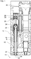
- the Figures 1 and 2nd show a valve 10 which is arranged in a cylinder head 12 of an internal combustion engine.
- the internal combustion engine can in a motor vehicle, preferably a commercial vehicle, for. B. trucks or buses.
- the valve 10 is designed as a compressed air extraction valve.
- the valve 10 is used for the selective removal of compressed air from a combustion chamber 14 covered by the cylinder head 12, e.g. B. during a compression cycle and / or during a push-out cycle.
- the compressed air can be used, for example, to operate an operating and / or parking brake device and / or an air suspension system of the motor vehicle.
- the valve 10 is not designed as a compressed air extraction valve and / or is included in a system that differs from an internal combustion engine.
- the valve 10 has a stem 16 and a plate element 18.
- the valve 10 can be actuated, preferably opened, via an actuating device 20.
- the valve 10 can, for example, be arranged adjacent to a receptacle for a fuel injector, as shown.
- the stem 16 is designed as an elongated valve stem of the valve 10.
- the shaft 16 is slidably mounted along its longitudinal axis A, z. B. in a valve guide.
- the shaft 16 can for example have a diameter of 6 mm ⁇ 50%, preferably 6 mm ⁇ 25%.
- the plate element 18 is arranged at a front end of the shaft 16.
- the plate element 18 is connected to the shaft 16, for. B. integrally made in one piece.
- the plate element 18 moves together with the shaft 16.
- the plate element 18 faces the combustion chamber 14.
- the plate element 18 can for example have a diameter of 14 mm ⁇ 50%, preferably 14 mm ⁇ 25%.
- valve 10 In a closed position of valve 10 (see Figure 1 ) essentially seals the plate element 18 between the combustion chamber 14 and a fluid channel (for example compressed air channel) 22 in the cylinder head 12. The plate element 18 bears against a valve seat 24 in the cylinder head 12. In an open position of the valve 10 (see Figure 2 ), the plate element 18 is spaced from the valve seat 24. Fluid, preferably compressed air, can flow from the combustion chamber 14 into the fluid channel 22.
- the actuating device 20 is designed to open the valve 10. To open the valve 10, the actuating device 20 moves the shaft 16 together with the plate element 18 in a direction toward the combustion chamber 14. The plate element 18 lifts off the valve seat 24 and releases a fluid connection to the fluid channel 22.
- the actuating device 20 can, as shown, be arranged at a rear end of the shaft 16. Other arrangements for the actuator 20 are also possible.
- the actuating device 20 can have a control chamber 26 and a control piston 28.
- the control piston 28 is received in the control chamber 26 in an axially displaceable manner.
- the control piston 28 is connected directly or indirectly to the shaft 16 for displacing the shaft 16.
- a fluid such as compressed air or hydraulic fluid
- the valve 10 is opened.
- the actuating device 20 can, for example, also be coupled to a lever device 30, for example an intake or exhaust valve rocker arm, of a valve drive, so that the actuating device 20 can expediently be actuated directly or indirectly even by the lever device 30. It is also possible for the actuating device 20 to actuate the valve 10 additionally or alternatively mechanically, electrically, electromagnetically and / or in another way hydraulically and / or pneumatically.
- the valve 10 can have a sealing device 32.
- the sealing device 32 can provide a fluid-tight seal between the shaft 16 and the valve guide.
- the valve 10 has a locking device 34.
- the locking device 34 is arranged on the cylinder head 12, here in principle different variants of the arrangement, for. B. in, on or on the cylinder head, are possible.
- the locking device 34 can be arranged with respect to a longitudinal axis of the valve 10 between the sealing device 32 and a rear end of the shaft 16.
- the locking device 34 can lock the valve 10 in its open position and its closed position. It is also possible that the locking device 34, for example depending on a construction of the actuating device 20, the valve 10 is locked either only in its open position or only in its closed position.
- the locking device 34 can be used particularly advantageously for locking the valve 10.
- the locking device 34 according to the present disclosure can also be used to lock other valves and also other stems, which are not included in a valve, for example.
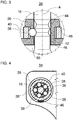
- the Figures 3 and 4 show the locking device 34 in a longitudinal sectional view and a cross-sectional view.
- the locking device 34 can expediently have a holder 36, a plurality of locking elements 38, a clamping ring 40 and grooves 42 and 44 on the shaft 16.
- the locking device 34 can also have, for example, more or fewer grooves and / or more or fewer locking elements than in the exemplary embodiment.
- the locking device 34 can advantageously be designed as a ball locking device with spherical locking elements 38.
- the bracket 36 is used to arrange the locking device 34 z. B. on the cylinder head 12 (see Figures 1 and 2nd ).
- the holder 36 holds the clamping ring 40 axially fixed with respect to a longitudinal axis A of the shaft 16 and radially displaceable or expandable.
- the holder 36 holds the plurality of locking elements 38 axially fixed and radially displaceable with respect to the longitudinal axis A.
- the holder 36 can have a suitably central, axial through hole 46 for the shaft 16.
- the through hole 46 is preferably axially aligned with the longitudinal axis A.
- the holder 36 can have an outer circumferential groove 48 for holding the clamping ring 40.
- the holder 36 can have a plurality of radial through holes 50 for holding the locking elements 38.
- the through holes 50 may extend between an inner circumferential surface of the through hole 46 and a bottom surface of the circumferential groove 48, preferably in a direction perpendicular to the longitudinal axis A.
- the through holes 50 may be arranged symmetrically around the shaft 16.
- the through holes 50 are preferably arranged in a rotationally symmetrical manner around the shaft 16, in particular N times in a rotationally symmetrical manner, where N here indicates the number of through holes 50.
- the plurality of locking elements 38 are arranged radially between the shaft 16 and the clamping ring 40.
- the shaft 16 is arranged radially on the inside of the locking elements 38.
- the clamping ring 40 is arranged radially on the outside of the locking elements 38.
- the locking elements 38 are held radially movable and axially immovable with respect to the longitudinal axis A.
- the locking elements 38 are designed such that they can engage in the grooves 42 and 44 for locking the shaft 16.
- the locking elements 38 are designed as balls, as shown.
- the plurality of locking elements 38 can be arranged symmetrically around the shaft 16.
- the locking elements 38 - like the through holes 50 - can be arranged in a rotationally symmetrical manner around the shaft 16, in particular N times in a rotationally symmetrical manner, where N indicates the number of the locking elements 38 here.
- the locking elements 38 expediently have an odd number, so that the locking elements 38 are not directly opposite one another and there is an improved centering of the shaft 16 by the locking elements 38.
- five locking elements 38 are included, for example.
- the clamping ring 40 surrounds the locking elements 38.
- the clamping ring 40 can have a flat inner circumferential surface, as shown. However, it is also possible for the clamping ring 40 to have, for example, a plurality of pockets for holding the locking elements 38 on its inner circumferential surface or an annular groove for holding the locking elements 38.
- the clamping ring 40 is arranged coaxially to the shaft 16 or the longitudinal axis A.
- the clamping ring 40 is designed such that the locking elements 38 are biased in a radial direction to the shaft 16.
- the locking elements 38 can thus engage in the grooves 42, 44. If the locking elements 38 engage, for example, in the groove 42, the valve 10 can be locked in its closed position (see Figure 1 ). If the locking elements 38 engage, for example, in the groove 44, the valve 10 can be locked in its open position (see Figure 2 ).
- the clamping ring 40 can be designed, for example, as an elastomer clamping ring, for example a rubber clamping ring, which derives the clamping force for prestressing the locking elements 38 from its elastic material properties.
- the clamping ring 40 it is also possible for the clamping ring 40 to be designed, for example, as an annular hose spring or annular helical spring.
- the grooves 42, 44 are arranged axially offset from one another with respect to the longitudinal axis A.
- the grooves 42, 44 are expediently designed as ring grooves in a lateral surface of the shaft 16.
- the grooves 42, 44 can for example each have a width of 3 mm ⁇ 50%, preferably 3 mm ⁇ 25%.
- the grooves 42, 44 are each designed such that they can move the locking elements 38 to release the locking of the shaft 16 with respect to the groove 42 or 44 in a radial direction away from the shaft 16.
- an axial force is applied to the shaft 16 in a direction of the desired displacement.
- the locking elements 38 are each pushed radially outwards by the respective groove 42 or 44.
- the shaft 16 can be pushed back and forth between a lock by means of the groove 42, for example to keep the valve 10 closed, and a lock by means of the groove 44, for example to keep the valve 10 open.
- the clamping ring 40 can be designed such that a locking force applied by the locking device 34 through the clamping ring 40 is 100 N ⁇ 50%, preferably 100 N ⁇ 25%.
- the axial force for pushing the locking elements 38 out of the groove 42 can be applied by the actuating device 20, expediently for opening the valve 10.
- the shaft 16 moves in a direction towards the combustion chamber 14 until it passes through the locking elements 38 engaging in the groove 44 is locked.
- An oppositely directed axial force which in turn exceeds the locking force, can then push the locking elements 38 out of the groove 44 again, for example for closing the valve 10.
- This oppositely directed axial force can be applied particularly advantageously by a gas force exerted on the plate element 18 the combustion chamber 14 acts.
- An increased cylinder pressure for example during a compression or extension stroke, can cause this gas force.
- the valve 10 for extracting compressed air can thus be operated, for example, as follows.
- the valve 10 is actuated by the actuator 20 for example at the beginning of the compression stroke or earlier, e.g. B. opened during or at the beginning of the intake stroke.
- the locking elements 38 are pushed out of the groove 42.
- the valve 10 is held open by the locking elements 38 which now engage in the groove 44.
- Compressed air flows through the open valve 10 into the fluid channel 22 and can thus be used as desired.
- the pressure in the combustion chamber 14 rises steadily.
- the cylinder pressure is so great that the through this caused gas force on the plate element 18 exceeds the locking force of the locking device 34.
- the locking elements 38 are pushed out of the groove 44.
- the valve 10 closes.
- the valve 10 is kept closed by the locking elements 38 engaging in the groove 44.
- the grooves 42 and 44 can, for example, be curved or chamfered, for example at an angle of 30 °.
- the locking elements 38 can be designed as balls, for. B with a ball diameter of 3 mm ⁇ 50%, preferably 3 mm ⁇ 25%.
- the locking elements 38 and / or the grooves 42, 44 are otherwise geometrically adapted to one another, as long as this enables the locking elements 38 to be pushed out of the grooves 42, 44.
- the contact surfaces of the locking elements 38 and / or the grooves 42, 44 can be curved, curved and / or bevelled.
- the clamping ring 40 When the locking elements 38 are pushed out of the groove 42 or 44, the clamping ring 40 is stretched radially outwards.
- a radially inwardly acting locking force caused by the clamping ring 40 can increase.
- the clamping ring 40 is expediently designed such that the increase in the locking force due to the expansion of the clamping ring 40 is less than 50% of the locking force when the locking elements 38 are in engagement with the groove 42 or 44.
- the clamping ring 40 can be designed such that the increase in the locking force due to the expansion of the clamping ring 40 is less than 30 N ⁇ 50%, preferably less than 30 N ⁇ 25%.
- the invention is not restricted to the preferred exemplary embodiments described above. Rather, a large number of variants and modifications are possible which also make use of the inventive idea and therefore fall within the scope of protection.
- the invention also claims protection for the subject and the features of the subclaims independently of the claims referred to.
- the features of independent claim 1 are disclosed independently of one another.
- the features of the subclaims are also disclosed independently of all the features of independent claim 1 and, for example, independently of the features relating to the presence and / or configuration of the tension ring, the shaft and / or the at least one locking element of independent claim 1. All area information disclosed herein are to be understood as meaning that, as it were, all values falling within the respective range are disclosed individually, e.g. B. also as the respective preferred narrower external borders of the respective area.
Landscapes
- Engineering & Computer Science (AREA)
- Mechanical Engineering (AREA)
- General Engineering & Computer Science (AREA)
- Chemical & Material Sciences (AREA)
- Combustion & Propulsion (AREA)
- Physics & Mathematics (AREA)
- Geometry (AREA)
- Valve Device For Special Equipments (AREA)
Abstract
Description
- Die Erfindung betrifft eine Arretiervorrichtung, vorzugsweise eine Kugel-Arretiervorrichtung, und ein Ventil, vorzugsweise ein Tellerventil, für eine Brennkraftmaschine, aufweisend eine Arretiervorrichtung.
- Ein Ventil kann mit einer Arretiervorrichtung ausgestattet sein, die es ermöglicht, das Ventil in einer bestimmen Stellung zu arretieren. Die Arretiervorrichtung kann auf unterschiedliche Weise ausgeführt sein.
- Zum Beispiel offenbart die
DE 40 35 376 A1 eine Betätigungseinrichtung für ein einen Ventilschaft aufweisendes Ladungswechselventil einer Brennkraftmaschine mit einer Schließfeder zum Bewegen des Ventils in eine Schließstellung. Der Ventilschaft trägt einen Magnetanker, der zusammen mit einer außerhalb des Ventils angeordneten, von einem Steuergerät angesteuerten Magnetwicklung eine Arretiervorrichtung für das in seine Öffnungsstellung bewegte Ventil bildet. -
DE 10 2004 027 967 B4 offenbart ein Gaswechselventil für eine Brennkraftmaschine, mit einem hydraulisch oder elektromechanisch betätigten Ventilglied und einer entgegen einer Öffnungsrichtung des Ventilglieds auf dasselbe einwirkenden Feder, die während des Betriebs der Brennkraftmaschine in gespanntem Zustand arretierbar ist. - Der Erfindung liegt die Aufgabe zu Grunde, eine alternative und/oder verbesserte Arretierung, vorzugsweise für ein Ventil, zu schaffen.
- Die Aufgabe wird gelöst durch die Merkmale des unabhängigen Anspruchs 1. Vorteilhafte Weiterbildungen sind in den abhängigen Ansprüchen und der Beschreibung angegeben.
- Die Erfindung schafft eine Arretiervorrichtung, vorzugsweise eine Kugel-Arretiervorrichtung, zweckmäßig für ein Ventil. Die Arretiervorrichtung weist einen Spannring auf. Die Arretiervorrichtung weist einen Schaft, vorzugsweise einen Ventilschaft (z. B. eines Hubventils, vorzugsweise eines Tellerventils), auf, der axial verschiebbar gelagert ist. Der Schaft ist koaxial innerhalb des Spannrings angeordnet und weist eine Nut, vorzugsweise eine Ringnut, auf. Die Arretiervorrichtung weist mindestens ein Arretierelement auf, das (z. B. radial) zwischen dem Schaft und dem Spannring angeordnet ist. Das mindestens eine Arretierelement ist radial bezüglich des Schafts bewegbar und von dem Spannring zum Eingreifen in die Nut zum axialen Arretieren des Schafts vorgespannt. Zweckmäßig verschiebt die Nut das mindestens eine Arretierelement zum Lösen der Arretierung des Schafts radial weg von dem Schaft (bzw. radial nach außen), wenn eine auf den Schaft wirkende Axialkraft eine durch den Spannring und das mindestens eine Arretierelement bewirkte Arretierkraft überschreitet, zweckmäßig unter einer radialen Dehnung des Spannrings nach außen.
- Die Arretiervorrichtung mit dem Spannring weist einen einfachen, kostengünstigen und doch wirkungsvollen Aufbau auf. Die Arretiervorrichtung kann sehr klein dimensioniert sein, sodass sie nicht viel Bauraum benötigt. Zum Freigeben der Arretierung sind zudem keine zusätzlichen Mittel erforderlich. Stattdessen ist das System lediglich so auszulegen, dass eine bestimmte Axialkraft auf den Schaft aufgebracht werden kann, die die Arretierkraft überschreitet, sodass die Arretierung gelöst wird. Es ist prinzipiell möglich, das die Axialkraft in beide Axialrichtungen aufgebracht werden kann, um den Schaft in der entsprechenden Richtung zu verschieben.
- Es ist möglich, dass das mindestens eine Arretierelement und der Spannring separat ausgebildet sind. Alternativ kann das mindestens eine Arretierelement integral-einstückig mit dem Spannring ausgebildet sein, vorzugsweise an einem Innenumfang des Spannrings. Bspw. kann das mindestens eine Arretierelement an den Spannring anvulkanisiert sein und/oder als eine, vorzugsweise innenseitige, Erhebung des Spannrings gebildet sein.
- In einem Ausführungsbeispiel weist die Nut eine gewölbte, gekrümmte, angefaste und/oder angeschrägte Kontaktfläche (vorzugsweise zum Kontaktieren des mindestens einen Arretierelements) zum radialen Ausschieben des mindestens einen Arretierelements auf. Alternativ oder zusätzlich weist das mindestens eine Arretierelement eine gewölbte, gekrümmte, angefaste und/oder angeschrägte Kontaktfläche (vorzugsweise zum Kontaktieren der Nut) auf, um von der Nut radial aus der Nut ausgeschoben zu werden. Die geometrische Anpassung der Nut an das mindestens eine Arretierelement ermöglicht das radiale Ausschieben aus der Nut durch die Nut zum Lösen der Arretierung.
- Es ist beispielsweise auch möglich, dass das mindestens eine Arretierelement eine Kugel ist.
- Zweckmäßig kann die Nut beispielsweise angefast sein, vorzugsweise in einem spitzen Winkel (z. B. 30°).
- In einem weiteren Ausführungsbeispiel weist der Schaft eine weitere Nut, vorzugsweise eine Ringnut, für das mindestens eine Arretierelement auf, wobei die weitere Nut axial versetzt zu der Nut ist. Somit kann der Schaft in einer ersten Stellung, zum Beispiel einer Öffnungsstellung eines Ventils, durch die Nut und in einer zweiten Stellung, zum Beispiel einer Schließstellung des Ventils, durch die zweite Nut arretiert werden.
- In einer Weiterbildung verschiebt die weitere Nut das mindestens eine Arretierelement zum Lösen der Arretierung des Schafts radial weg von dem Schaft, wenn eine auf den Schaft wirkende Axialkraft eine durch den Spannring und das mindestens eine Arretierelement bewirkte Arretierkraft überschreitet. Somit müssen keine zusätzlichen Mittel zum Lösen der Arretierung durch den Eingriff des mindestens einen Arretierelements in die weitere Nut vorgesehen werden.
- Es ist möglich, dass die weitere Nut, zum Beispiel teilweise oder vollständig, wie die Nut ausgeführt ist.
- In einer Ausführungsform weist das mindestens eine Arretierelement mehrere in Umfangsrichtung um den Schaft herum angerordnete Arretierelemente auf, die vorzugsweise symmetrisch (z. B. drehsymmetrisch) um den Schaft herum angeordnet sind und/oder vorzugsweise eine ungerade Anzahl aufweisen. Die mehreren, symmetrisch angeordneten Arretierelemente ermöglichen eine gleichmäßige Arretierung des Schafts um dessen Umfang. Die vorzugsweise ungerade Anzahl führt dazu, dass sich Arretierelemente nicht direkt gegenüber liegen, sodass sich beispielsweise eine Zentrierung durch die Arretierelemente verbessern lässt.
- In einer weiteren Ausführungsform weist die Arretiervorrichtung eine Halterung auf, die das mindestens eine Arretierelement und/oder den Spannring hält.
- Es ist möglich, dass die Halterung in einem Ventil umfasst ist und/oder in einem Zylinderkopf einer Brennkraftmaschine angeordnet, vorzugsweise befestigt, ist.
- In einer Weiterbildung hält die Halterung das mindestens eine Arretierelement und/oder den Spannring bezüglich einer Axialrichtung des Schafts fest. Alternativ oder zusätzlich hält die Halterung das mindestens eine Arretierelement und/oder den Spannring bezüglich einer Radialrichtung des Schafts beweglich, vorzugsweise verschiebbar.
- In einem weiteren Ausführungsbeispiel weist die Halterung eine äußere Umfangsnut auf, in der der Spannring gehalten ist. Alternativ oder zusätzlich weist die Halterung ein (zum Beispiel zentrales) axiales Durchgangsloch für den Schaft auf. Alternativ oder ergänzend weist die Halterung mindestens ein radiales Durchgangsloch auf, in dem das mindestens eine Arretierelement gehalten ist.
- In einer Ausführungsvariante ist der Spannring als ein Elastomer-Spannring, vorzugsweise ein Gummispannring, oder eine Schlauchfeder ausgebildet.
- In einer weiteren Ausführungsvariante liegt der Spannring an dem mindestens einen Arretierelement, z. B. radial außen, an. Alternativ oder zusätzlich kann der Spannring an einer Innenumfangsfläche des Spannrings mindestens eine Aufnahme (z. B. Ringnut oder Tasche) zum Halten des mindestens einen Arretierelements aufweisen.
- Die Erfindung betrifft auch ein Ventil (zum Beispiel Hubventil), vorzugsweise Tellerventil, beispielsweise für eine Brennkraftmaschine. Das Ventil weist einen Ventilschaft und eine Arretiervorrichtung wie hierin offenbart auf. Vorzugsweise ist der Schaft der Arretiervorrichtung der Ventilschaft des Ventils.
- In einer Weiterbildung ist das Ventil in einer Öffnungsstellung arretiert, wenn das mindestens eine Arretierelement in die Nut eingreift. Alternativ oder zusätzlich kann das Ventil in einer Schließstellung arretiert sein, wenn das mindestens eine Arretierelement in die weitere Nut eingreift. Damit kann das Ventil durch die Arretiervorrichtung in der Öffnungsstellung und/oder in der Schließstellung arretiert werden.
- In einer Ausführungsform ist das Ventil ein Druckluftentnahmeventil zur selektiven Entnahme von Druckluft aus einer Verbrennungskammer der Brennkraftmaschine.
- Zweckmäßig kann das Druckluftentnahmeventil zusätzlich bzw. separat von den Gaswechselventilen, zum Beispiel Lufteinlassventile und Abgasauslassventile, der Brennkraftmaschine vorgesehen bzw. angeordnet sein.
- In einer weiteren Ausführungsform ist das Ventil elektrisch, elektromagnetisch, mechanisch, pneumatisch und/oder hydraulisch zum axialen Verschieben des Schafts in eine Öffnungsstellung des Ventils, betätigbar. Vorzugsweise greift das mindestens eine Arretierelement in die Nut zum Arretieren des Schafts ein, wenn das Ventil in der Öffnungsstellung ist.
- In einer weiteren Ausführungsform ist das Ventil mittels einer auf ein beispielsweise brennraumseitiges Tellerelement des Ventils wirkenden Gaskraft, die vorzugsweise durch einen Zylinderdruck in einer Verbrennungskammer der Brennkraftmaschine bewirkt wird, betätigbar, vorzugsweise schließbar. Vorzugsweise wird die die Arretierkraft überschreitende Axialkraft zum Lösen der Arretierung teilweise oder vollständig durch die Gaskraft bewirkt. Es ist möglich, dass bspw. zusätzlich ein elastisches Element, z. B. eine Feder, angeordnet ist, das die Arretierkraft erhöht.
- Beispielsweise kann die Gaskraft bewirken, dass die axiale Arretierung durch Ausschieben des mindestens einen Arretierelements aus der Nut durch die Nut gelöst wird.
- Die vorliegende Offenbarung betrifft somit zweckmäßig auch eine Verwendung des hierin offenbarten Ventils bzw. ein Verfahren zum Betätigen eines Ventils wie hierin offenbart. Die Verwendung bzw. das Verfahren weist ein Lösen einer Arretierung durch die Arretiervorrichtung des in einer Öffnungsstellung positionierten Ventils durch Aufbringen einer Axialkraft auf den Ventilschaft mittels einer Gaskraft, die durch einen Zylinderdruck in einer Verbrennungskammer der Brennkraftmaschine bewirkt wird, auf. Vorzugsweise wirkt die Gaskraft auf ein beispielsweise brennraumseitiges Tellerelement des Ventils.
- Die Erfindung betrifft auch ein Kraftfahrzeug, vorzugsweise ein Nutzfahrzeug (z. B. Lastkraftwagen oder Omnibus), mit einer Arretiervorrichtung wie hierin offenbart oder einem Ventil wie hierin offenbart.
- Es ist auch möglich, die Vorrichtung wie hierin offenbart für Personenkraftwagen, Großmotoren, geländegängige Fahrzeuge, stationäre Motoren, Marinemotoren, andere Anlagen usw. zu verwenden.
- Die zuvor beschriebenen bevorzugten Ausführungsformen und Merkmale der Erfindung sind beliebig miteinander kombinierbar. Weitere Einzelheiten und Vorteile der Erfindung werden im Folgenden unter Bezug auf die beigefügten Zeichnungen beschrieben. Es zeigen:
- Figur 1
- eine Schnittansicht durch einen Abschnitt eines Zylinderkopfes mit einem Ventil gemäß einem Ausführungsbeispiel der vorliegenden Offenbarung in einer Schließstellung;
- Figur 2
- eine Schnittansicht gemäß
Figur 1 , mit dem beispielhaften Ventil in einer Öffnungsstellung; - Figur 3
- eine Längsschnittansicht einer Arretiervorrichtung des beispielhaften Ventils; und
- Figur 4
- eine Querschnittansicht der beispielhaften Arretiervorrichtung.
- Die in den Figuren gezeigten Ausführungsformen stimmen zumindest teilweise überein, so dass ähnliche oder identische Teile mit den gleichen Bezugszeichen versehen sind und zu deren Erläuterung auch auf die Beschreibung der anderen Ausführungsformen bzw. Figuren verwiesen wird, um Wiederholungen zu vermeiden.
- Die
Figuren 1 und2 zeigen ein Ventil 10, das in einem Zylinderkopf 12 einer Brennkraftmaschine angeordnet ist. Die Brennkraftmaschine kann in einem Kraftfahrzeug, vorzugsweise einem Nutzfahrzeug, z. B. Lastkraftwagen oder Omnibus, umfasst sein. - Im Ausführungsbeispiel ist das Ventil 10 als ein Druckluftentnahmeventil ausgeführt. Das Ventil 10 dient zur selektiven Entnahme von Druckluft aus einer von dem Zylinderkopf 12 abgedeckten Verbrennungskammer 14, z. B. während eines Verdichtungstaktes und/oder während eines Ausschiebetaktes. Die Druckluft kann beispielsweise zum Betreiben einer Betriebs- und/oder Feststellbremsvorrichtung und/oder einer Luftfederanlage des Kraftfahrzeugs verwendet werden. Es ist allerdings auch möglich, dass das Ventil 10 nicht als Druckluftentnahmeventil ausgeführt ist und/oder in einer Anlage, die sich von einer Brennkraftmaschine unterscheidet, umfasst ist.
- Das Ventil 10 weist einen Schaft 16 und ein Tellerelement 18 auf. Das Ventil 10 kann über eine Betätigungseinrichtung 20 betätigt, vorzugsweise geöffnet, werden. Das Ventil 10 kann beispielsweise benachbart zu einer Aufnahme für einen Kraftstoffinjektor angeordnet sein, wie dargestellt ist.
- Der Schaft 16 ist als ein länglicher Ventilschaft des Ventils 10 ausgeführt. Der Schaft 16 ist entlang seiner Längsachse A verschiebbar gelagert, z. B. in einer Ventilführung. Der Schaft 16 kann beispielsweise einen Durchmesser von 6 mm ± 50 %, vorzugsweise 6 mm ± 25 %, aufweisen.
- Das Tellerelement 18 ist an einem vorderen Ende des Schafts 16 angeordnet. Das Tellerelement 18 ist mit dem Schaft 16 verbunden, z. B. integral einstückig ausgeführt. Das Tellerelement 18 bewegt sich gemeinsam mit dem Schaft 16. Das Tellerelement 18 ist der Verbrennungskammer 14 zugewandt. Das Tellerelement 18 kann beispielsweise einen Durchmesser von 14 mm ± 50 %, vorzugsweise 14 mm ± 25 %, aufweisen.
- In einer Schließstellung des Ventils 10 (siehe
Figur 1 ) dichtet das Tellerelement 18 im Wesentlichen zwischen der Verbrennungskammer 14 und einem Fluidkanal (zum Beispiel Druckluftkanal) 22 im Zylinderkopf 12 ab. Das Tellerelement 18 liegt an einem Ventilsitz 24 im Zylinderkopf 12 an. In einer Öffnungsstellung des Ventils 10 (sieheFigur 2 ) ist das Tellerelement 18 beabstandet von dem Ventilsitz 24. Fluid, vorzugsweise Druckluft, aus der Verbrennungskammer 14 kann in den Fluidkanal 22 strömen. - Die Betätigungseinrichtung 20 ist dazu ausgebildet, das Ventil 10 zu öffnen. Zum Öffnen des Ventils 10 verschiebt die Betätigungseinrichtung 20 den Schaft 16 zusammen mit dem Tellerelement 18 in einer Richtung zu der Verbrennungskammer 14. Das Tellerelement 18 hebt vom Ventilsitz 24 ab und gibt eine Fluidverbindung zu dem Fluidkanal 22 frei. Die Betätigungseinrichtung 20 kann, wie dargestellt ist, an einem hinteren Ende des Schafts 16 angeordnet sein. Andere Anordnungen für die Betätigungseinrichtung 20 sind ebenfalls möglich.
- Beispielsweise kann die Betätigungseinrichtung 20 eine Steuerkammer 26 und einen Steuerkolben 28 aufweisen. Der Steuerkolben 28 ist axial verschiebbar in der Steuerkammer 26 aufgenommen. Der Steuerkolben 28 ist direkt oder indirekt mit dem Schaft 16 zum Verschieben des Schafts 16 verbunden. Wenn beispielsweise die Steuerkammer 26 mit einem Fluid, zum Beispiel Druckluft oder Hydraulikfluid, beaufschlagt wird, wird der Steuerkolben 28 in einer Axialrichtung zu dem Schaft 16 verschoben. Das Ventil 10 wird geöffnet. Die Betätigungseinrichtung 20 kann beispielsweise auch mit einer Hebelvorrichtung 30, zum Beispiel einem Einlass- oder Auslassventilkipphebel, eines Ventiltriebs gekoppelt sein, sodass die Betätigungseinrichtung 20 zweckmäßig selbst von Hebelvorrichtung 30 direkt oder indirekt betätigbar ist. Es ist auch möglich, dass die Betätigungseinrichtung 20 das Ventil 10 zusätzlich oder alternativ mechanisch, elektrisch, elektromagnetisch und/oder andersartig hydraulisch und/oder pneumatisch betätigt.
- Das Ventil 10 kann eine Dichtvorrichtung 32 aufweisen. Die Dichtvorrichtung 32 kann zwischen dem Schaft 16 und der Ventilführung fluiddicht abdichten.
- Das Ventil 10 weist eine Arretiervorrichtung 34 auf. Die Arretiervorrichtung 34 ist am Zylinderkopf 12 angeordnet, wobei hier prinzipiell verschiedene Varianten der Anordnung, z. B. in, an oder auf dem Zylinderkopf, möglich sind. Beispielsweise kann die Arretiervorrichtung 34 bezüglich einer Längsachse des Ventils 10 zwischen der Dichtvorrichtung 32 und einem hinteren Ende des Schafts 16 angeordnet sein. Die Arretiervorrichtung 34 kann das Ventil 10 in dessen Öffnungsstellung und dessen Schließstellung arretieren. Es ist auch möglich, dass die Arretiervorrichtung 34, zum Beispiel in Abhängigkeit von einer Konstruktion der Betätigungseinrichtung 20, das Ventil 10 entweder nur in dessen Öffnungsstellung oder nur in dessen Schließstellung arretiert.
- Nachfolgend ist unter Bezugnahme auf die
Figuren 3 und 4 eine beispielhafte Ausführungsform für die Arretiervorrichtung 34 beschrieben, die besonders vorteilhaft zum Arretieren des Ventils 10 verwendet werden kann. Es wurde allerdings erkannt, dass die Arretiervorrichtung 34 gemäß der vorliegenden Offenbarung auch zum Arretieren anderer Ventile und auch anderer Schäfte, die beispielsweise nicht in einem Ventil umfasst sind, eingesetzt werden kann. - Die
Figuren 3 und 4 zeigen die Arretiervorrichtung 34 in einer Längsschnittansicht und einer Querschnittansicht. - Die Arretiervorrichtung 34 kann zweckmäßig eine Halterung 36, mehrere Arretierelemente 38, einen Spannring 40 und Nuten 42 und 44 am Schaft 16 aufweisen. Die Arretiervorrichtung 34 kann beispielsweise auch mehr oder weniger Nuten und/oder mehr oder weniger Arretierelemente als im Ausführungsbeispiel aufweisen. Vorteilhaft kann die Arretiervorrichtung 34, wie dargestellt ist, als eine Kugel-Arretiervorrichtung mit kugelförmigen Arretierelementen 38 ausgebildet sein.
- Die Halterung 36 dient zur Anordnung der Arretiervorrichtung 34 z. B. am Zylinderkopf 12 (siehe
Figuren 1 und2 ). Die Halterung 36 hält den Spannring 40 bezüglich einer Längsachse A des Schafts 16 axial fest und radial verschiebbar bzw. dehnbar. Die Halterung 36 hält die mehreren Arretierelemente 38 bezüglich der Längsachse A axial fest und radial verschiebbar. - Die Halterung 36 kann ein zweckmäßig zentrales, axiales Durchgangsloch 46 für den Schaft 16 aufweisen. Das Durchgangsloch 46 ist vorzugsweise axial mit der Längsachse A ausgerichtet. Die Halterung 36 kann eine äußere Umfangsnut 48 zum Halten des Spannrings 40 aufweisen. Die Halterung 36 kann mehrere radiale Durchgangslöcher 50 zum Halten der Arretierelemente 38 aufweisen. Die Durchgangslöcher 50 können sich zwischen einer Innenumfangsfläche des Durchgangslochs 46 und einer Bodenfläche der Umfangsnut 48 erstrecken, vorzugsweise in einer Richtung senkrecht zur Längsachse A. Die Durchgangslöcher 50 können symmetrisch um den Schaft 16 herum angeordnet sein. Vorzugsweise sind die Durchgangslöcher 50 drehsymmetrisch um den Schaft 16 herum angeordnet, insbesondere N-fach drehsymmetrisch, wobei N hier die Anzahl der Durchgangslöcher 50 angibt.
- Die mehreren Arretierelemente 38 sind radial zwischen dem Schaft 16 und dem Spannring 40 angeordnet. Der Schaft 16 ist radial innenliegend von den Arretierelementen 38 angeordnet. Der Spannring 40 ist radial außenliegend von den Arretierelementen 38 angeordnet. Die Arretierelemente 38 sind bezüglich der Längsachse A radial beweglich und axial unbeweglich gehalten. Die Arretierelemente 38 sind so ausgeführt, dass sie in die Nuten 42 und 44 zum Arretieren des Schafts 16 eingreifen können. Beispielsweise sind die Arretierelemente 38 als Kugeln ausgeführt, wie dargestellt ist.
- Die mehreren Arretierelemente 38 können symmetrisch um den Schaft 16 herum angeordnet sein. Zweckmäßig können die Arretierelemente 38 - wie die Durchgangslöcher 50 - drehsymmetrisch um den Schaft 16 herum angeordnet sein, insbesondere N-fach drehsymmetrisch, wobei N hier die Anzahl der Arretierelemente 38 angibt. Zweckmäßig weisen die Arretierelemente 38 eine ungerade Anzahl auf, sodass sich die Arretierelemente 38 nicht direkt gegenüber liegen und sich eine verbesserte Zentrierung des Schafts 16 durch die Arretierelemente 38 ergibt. Im Ausführungsbeispiel sind beispielsweise fünf Arretierelemente 38 umfasst.
- Der Spannring 40 umgibt die Arretierelemente 38. Der Spannring 40 kann eine flächige Innenumfangsfläche aufweisen, wie dargestellt ist. Es ist aber auch möglich, dass der Spannring 40 an dessen Innenumfangsfläche beispielsweise mehrere Taschen zum Halten der Arretierelemente 38 oder eine Ringnut zum Halten der Arretierelemente 38 aufweist.
- Der Spannring 40 ist koaxial zum Schaft 16 bzw. der Längsachse A angeordnet. Der Spannring 40 ist so ausgebildet, dass die Arretierelemente 38 in einer Radialrichtung zu dem Schaft 16 vorgespannt sind. Somit können die Arretierelemente 38 in die Nuten 42, 44 eingreifen. Greifen die Arretierelemente 38 beispielsweise in die Nut 42 ein, kann das Ventil 10 in dessen Schließstellung arretiert sein (siehe
Figur 1 ). Greifen die Arretierelemente 38 beispielsweise in die Nut 44 ein, kann das Ventil 10 in dessen Öffnungsstellung arretiert sein (sieheFigur 2 ). - Der Spannring 40 kann beispielsweise als ein Elastomer-Spannring, zum Beispiel ein Gummispannring ausgeführt sein, der die Spannkraft zum Vorspannen der Arretierelemente 38 aus dessen elastischen Materialeigenschaften ableitet. Es ist allerdings auch möglich, dass der Spannring 40 beispielsweise als eine ringförmige Schlauchfeder oder ringförmige Schraubenfeder ausgeführt ist.
- Die Nuten 42, 44 sind bezüglich der Längsachse A axial versetzt zueinander angeordnet. Die Nuten 42, 44 sind zweckmäßig als Ringnuten in einer Mantelfläche des Schafts 16 ausgebildet. Die Nuten 42, 44 können beispielsweise jeweils eine Breite von 3 mm ± 50 %, vorzugsweise 3 mm ± 25 %, aufweisen.
- Die Nuten 42, 44 sind jeweils so ausgeführt, dass sie die Arretierelemente 38 zum Lösen der Arretierung des Schafts 16 bezüglich der Nut 42 oder 44 in einer Radialrichtung weg von dem Schaft 16 verschieben können. Hierzu wird eine Axialkraft auf den Schaft 16 in einer Richtung der gewünschten Verschiebung aufgebracht. Wenn die aufgebrachte Axialkraft die durch den Spannring 40 und die Arretierelemente 38 aufgebrachte Arretierkraft überschreitet, werden die Arretierelemente 38 von der jeweiligen Nut 42 oder 44 jeweils radial nach außen gedrückt. So kann der Schaft 16 beispielsweise zwischen einer Arretierung mittels der Nut 42, zum Beispiel zum Geschlossenhalten des Ventils 10, und einer Arretierung mittels der Nut 44, zum Beispiel zum Offenhalten des Ventils 10, hin- und hergeschoben werden. Beispielsweise kann der Spannring 40 so ausgebildet sein, dass eine von der Arretiervorrichtung 34 durch den Spannring 40 aufgebrachte Arretierkraft 100 N ± 50 %, vorzugsweise 100 N ± 25 %, beträgt.
- Beispielsweise kann die Axialkraft zum Ausschieben der Arretierelemente 38 aus der Nut 42 von der Betätigungseinrichtung 20 aufgebracht werden, zweckmäßig zum Öffnen des Ventils 10. Der Schaft 16 bewegt sich in einer Richtung zu der Verbrennungskammer 14 bis er durch die in die Nut 44 eingreifenden Arretierelemente 38 arretiert wird. Eine entgegengesetzt gerichtete Axialkraft, die wiederum die Arretierkraft überschreitet, kann die Arretierelemente 38 dann wieder aus der Nut 44 ausschieben, zum Beispiel zum Schließen des Ventils 10. Diese entgegengesetzt gerichtete Axialkraft kann besonders vorteilhaft durch eine Gaskraft aufgebracht werden, die auf das Tellerelement 18 aus der Verbrennungskammer 14 wirkt. Ein erhöhter Zylinderdruck beispielsweise während eines Verdichtungs- oder Ausschubtaktes kann diese Gaskraft bewirken.
- Somit kann das Ventil 10 zur Druckluftentnahme beispielsweise wie folgt betätigt werden. Das Ventil 10 wird durch die Betätigungseinrichtung 20 beispielsweise zu Beginn des Verdichtungstaktes oder früher, z. B. während oder zu Beginn des Ansaugtaktes, geöffnet. Dabei werden die Arretierelemente 38 aus der Nut 42 ausgeschoben. Das Ventil 10 wird durch die nun in die Nut 44 eingreifenden Arretierelemente 38 offengehalten. Verdichtete Luft strömt durch das offen gehaltene Ventil 10 in den Fluidkanal 22 und kann somit wie gewünscht weiterverwendet werden. Während des Verdichtungstaktes steigt der Druck in der Verbrennungskammer 14 stetig an. Zu einem bestimmten Zeitpunkt ist der Zylinderdruck so groß, dass die durch diesen bewirkte Gaskraft auf das Tellerelement 18 die Arretierkraft der Arretiervorrichtung 34 überschreitet. Die Arretierelemente 38 werden aus der Nut 44 ausgeschoben. Das Ventil 10 schließt. Das Ventil 10 wird durch die in die Nut 44 eingreifenden Arretierelemente 38 geschlossen gehalten.
- Um ein Ausschieben der Arretierelemente 38 aus den Nuten 42 und 44 zu ermöglichen, sind diese zweckmäßig geometrisch aneinander angepasst. Wie dargestellt ist, können die Nuten 42 und 44 beispielsweise gewölbt oder angefast, zum Beispiel mit einem Winkel von 30°, ausgebildet sein. Die Arretierelemente 38 können als Kugeln ausgebildet sein, z. B mit einem Kugeldurchmesser von 3 mm ± 50 %, vorzugsweise 3 mm ± 25 %. Es ist allerdings auch möglich, dass die Arretierelemente 38 und/oder die Nuten 42, 44 anderweitig aneinander geometrisch angepasst sind, solange dadurch ein Ausschieben der Arretierelemente 38 aus den Nuten 42, 44 ermöglicht wird. Beispielsweise können die Kontaktflächen der Arretierelemente 38 und/oder der Nuten 42, 44 gewölbt, gekrümmt und/oder angeschrägt sein.
- Beim Ausschieben der Arretierelemente 38 aus der Nut 42 oder 44 wird der Spannring 40 radial nach außen gedehnt. Hierbei kann sich eine durch den Spannring 40 bewirkte radial nach innen wirkende Arretierkraft erhöhen. Zweckmäßig ist der Spannring 40 so ausgebildet, dass sich die Vergrößerung der Arretierkraft durch die Dehnung des Spannrings 40 in einem Bereich kleiner als 50 % der Arretierkraft, wenn die Arretierelemente 38 in Eingriff mit der Nut 42 oder 44 sind, beträgt. Beispielsweise kann der Spannring 40 so ausgebildet, dass die Vergrößerung der Arretierkraft durch die Dehnung des Spannrings 40 kleiner als 30 N ± 50 %, vorzugsweise kleiner als 30 N ± 25 %, ist.
- Die Erfindung ist nicht auf die vorstehend beschriebenen bevorzugten Ausführungsbeispiele beschränkt. Vielmehr ist eine Vielzahl von Varianten und Abwandlungen möglich, die ebenfalls von dem Erfindungsgedanken Gebrauch machen und deshalb in den Schutzbereich fallen. Insbesondere beansprucht die Erfindung auch Schutz für den Gegenstand und die Merkmale der Unteransprüche unabhängig von den in Bezug genommenen Ansprüchen. Insbesondere sind die Merkmale des unabhängigen Anspruchs 1 unabhängig voneinander offenbart. Zusätzlich sind auch die Merkmale der Unteransprüche unabhängig von sämtlichen Merkmalen des unabhängigen Anspruchs 1 und beispielsweise unabhängig von den Merkmalen bezüglich des Vorhandenseins und/oder der Konfiguration des Spannrings, des Schafts und/oder des mindestens einen Arretierelements des unabhängigen Anspruchs 1 offenbart. Alle Bereichsangaben hierin sind derart offenbart zu verstehen, dass gleichsam alle in den jeweiligen Bereich fallenden Werte einzeln offenbart sind, z. B. auch als jeweilige bevorzugte engere Außengrenzen des jeweiligen Bereichs.
-
- A
- Längsachse
- 10
- Ventil
- 12
- Zylinderkopf
- 14
- Verbrennungskammer
- 16
- Schaft
- 18
- Tellerelement
- 20
- Betätigungseinrichtung
- 22
- Fluidkanal
- 24
- Ventilsitz
- 26
- Steuerkammer
- 28
- Steuerkolben
- 30
- Hebelvorrichtung
- 32
- Dichtvorrichtung
- 34
- Arretiervorrichtung
- 36
- Halterung
- 38
- Arretierelement
- 40
- Spannring
- 42
- Nut
- 44
- Nut
- 46
- Durchgangsloch
- 48
- Umfangsnut
- 50
- Durchgangsloch
Claims (15)
- Arretiervorrichtung (34), vorzugsweise Kugel-Arretiervorrichtung, aufweisend:einen Spannring (40);einen Schaft (16), vorzugsweise einen Ventilschaft, der axial verschiebbar gelagert ist, koaxial innerhalb des Spannrings (40) angeordnet ist und eine Nut (44), vorzugsweise eine Ringnut, aufweist; undmindestens ein Arretierelement (38), das zwischen dem Schaft (16) und dem Spannring (40) angeordnet ist, radial bezüglich des Schafts (16) bewegbar ist und von dem Spannring (40) zum Eingreifen in die Nut (44) zum axialen Arretieren des Schafts (16) vorgespannt ist;wobei die Nut (44) das mindestens eine Arretierelement (38) zum Lösen der Arretierung des Schafts (16) radial weg von dem Schaft (16) verschiebt, wenn eine auf den Schaft (16) wirkende Axialkraft eine durch den Spannring (40) und das mindestens eine Arretierelement (38) bewirkte Arretierkraft überschreitet.
- Arretiervorrichtung (34) nach Anspruch 1, wobeidie Nut (44) eine gewölbte, gekrümmte, angefaste und/oder angeschrägte Kontaktfläche zum radialen Ausschieben des mindestens einen Arretierelements (38) aufweist; und/oderdas mindestens eine Arretierelement (38) eine gewölbte, gekrümmte, angefaste und/oder angeschrägte Kontaktfläche aufweist, um von der Nut (44) radial aus der Nut (44) ausgeschoben zu werden; und/oderdas mindestens eine Arretierelement (38) eine Kugel ist.
- Arretiervorrichtung (34) nach Anspruch 1 oder Anspruch 2, wobei:
der Schaft (16) eine weitere Nut (42), vorzugsweise eine Ringnut, für das mindestens eine Arretierelement (38) aufweist, wobei die weitere Nut (42) axial versetzt zu der Nut (44) ist. - Arretiervorrichtung (34) nach Anspruch 3, wobei:die weitere Nut (42) das mindestens eine Arretierelement (38) zum Lösen der Arretierung des Schafts (16) radial weg von dem Schaft (16) verschiebt, wenn eine auf den Schaft (16) wirkende Axialkraft eine durch den Spannring (40) und das mindestens eine Arretierelement (38) bewirkte Arretierkraft überschreitet; und/oderdie weitere Nut (42) wie die Nut (44) ausgeführt ist.
- Arretiervorrichtung (34) nach einem der vorherigen Ansprüche, wobei:
das mindestens eine Arretierelement (38) mehrere in Umfangsrichtung um den Schaft (16) herum angerordnete Arretierelemente (38) aufweist, die symmetrisch um den Schaft (16) herum angeordnet sind und eine ungerade Anzahl aufweisen. - Arretiervorrichtung (34) nach einem der vorherigen Ansprüche, ferner aufweisend:
eine Halterung (36), die das mindestens eine Arretierelement (38) und/oder den Spannring (40) hält. - Arretiervorrichtung (34) nach Anspruch 6, wobei:die Halterung (36) das mindestens eine Arretierelement (38) und/oder den Spannring (40) bezüglich einer Axialrichtung des Schafts (16) fest hält; und/oderdie Halterung (36) das mindestens eine Arretierelement (38) und/oder den Spannring (40) bezüglich einer Radialrichtung des Schafts (16) beweglich hält; und/oderdie Halterung (36) eine äußere Umfangsnut (48) aufweist, in der der Spannring (40) gehalten ist; und/oderdie Halterung (36) ein axiales Durchgangsloch (46) für den Schaft (16) aufweist; und/oderdie Halterung (36) mindestens ein radiales Durchgangsloch (50) aufweist, in dem das mindestens eine Arretierelement (38) gehalten ist.
- Arretiervorrichtung (34) nach einem der vorherigen Ansprüche, wobei:
der Spannring (40) als ein Elastomer-Spannring, vorzugsweise ein Gummispannring, oder eine Schlauchfeder ausgebildet ist. - Arretiervorrichtung (34) nach einem der vorherigen Ansprüche, wobei:der Spannring (40) an dem mindestens einen Arretierelement (38) anliegt; und/oderder Spannring (40) an einer Innenumfangsfläche des Spannrings (40) mindestens eine Aufnahme zum Halten des mindestens einen Arretierelements (38) aufweist.
- Ventil (10), vorzugsweise Tellerventil, für eine Brennkraftmaschine, aufweisend:einen Ventilschaft; undeine Arretiervorrichtung (34) nach einem der vorherigen Ansprüche, wobei der Schaft (16) der Arretiervorrichtung (34) der Ventilschaft des Ventils (10) ist.
- Ventil (10) nach Anspruch 10, wobei:das Ventil (10) in einer Öffnungsstellung arretiert ist, wenn das mindestens eine Arretierelement (38) in die Nut (44) eingreift; und/oderdas Ventil (10) in einer Schließstellung arretiert ist, wenn das mindestens eine Arretierelement (38) in die weitere Nut (42) eingreift.
- Ventil (10) nach Anspruch 10 oder Anspruch 11, wobei:
das Ventil (10) ein Druckluftentnahmeventil zur selektiven Entnahme von Druckluft aus einer Verbrennungskammer (14) der Brennkraftmaschine ist. - Ventil (10) nach einem der Ansprüche 10 bis 12, wobei:
das Ventil (10) elektrisch, elektromagnetisch, mechanisch, pneumatisch und/oder hydraulisch zum axialen Verschieben des Schafts (16) in eine Öffnungsstellung des Ventils (10), in der das mindestens eine Arretierelement (38) in die Nut (44) zum Arretieren des Schafts (16) eingreift, betätigbar ist. - Ventil (10) nach einem der Ansprüche 10 bis 13, wobei:
das Ventil (10) mittels einer auf ein Tellerelement (18) des Ventils (10) wirkenden Gaskraft, die vorzugsweise durch einen Zylinderdruck in einer Verbrennungskammer (14) der Brennkraftmaschine bewirkt wird, betätigbar, vorzugsweise schließbar, ist, wobei die die Arretierkraft überschreitende Axialkraft zum Lösen der Arretierung teilweise oder vollständig durch die Gaskraft bewirkt wird. - Kraftfahrzeug, vorzugsweise Nutzfahrzeug, mit einer Arretiervorrichtung (34) nach einem der Ansprüche 1 bis 9 oder einem Ventil (10) nach einem der Ansprüche 10 bis 14.
Applications Claiming Priority (1)
| Application Number | Priority Date | Filing Date | Title |
|---|---|---|---|
| DE102018121722.6A DE102018121722A1 (de) | 2018-09-06 | 2018-09-06 | Arretiervorrichtung und Ventil mit einer Arretiervorrichtung |
Publications (2)
| Publication Number | Publication Date |
|---|---|
| EP3620636A1 true EP3620636A1 (de) | 2020-03-11 |
| EP3620636B1 EP3620636B1 (de) | 2021-08-25 |
Family
ID=67810423
Family Applications (1)
| Application Number | Title | Priority Date | Filing Date |
|---|---|---|---|
| EP19194529.4A Active EP3620636B1 (de) | 2018-09-06 | 2019-08-30 | Druckluftentnahmeventil |
Country Status (2)
| Country | Link |
|---|---|
| EP (1) | EP3620636B1 (de) |
| DE (1) | DE102018121722A1 (de) |
Citations (7)
| Publication number | Priority date | Publication date | Assignee | Title |
|---|---|---|---|---|
| US3403667A (en) * | 1967-06-26 | 1968-10-01 | Briggs & Stratton Corp | Compression relief for internal combustion engines |
| US3665813A (en) * | 1970-02-24 | 1972-05-30 | Gen Gas Light Co | Snap operator for pressure fluid valve |
| DE3903474A1 (de) * | 1988-02-25 | 1989-09-07 | Avl Verbrennungskraft Messtech | Verfahren zum betrieb einer brennkraftmaschine |
| DE4035376A1 (de) | 1989-11-16 | 1991-05-23 | Volkswagen Ag | Betaetigungseinrichtung fuer ein hubventil |
| DE4309860C1 (de) * | 1993-03-26 | 1994-06-09 | Daimler Benz Ag | Vorrichtung zur Steuerung von in einem Zylinder einer Brennkraftmaschine komprimierter Luft |
| EP0659947A2 (de) * | 1993-12-21 | 1995-06-28 | Roediger Anlagenbau GmbH | Steueranordnung für ein durch Unterdruck betätigbares Absperrventil |
| DE102004027967B4 (de) | 2004-06-08 | 2008-06-12 | Audi Ag | Gaswechselventil für eine Brennkraftmaschine |
Family Cites Families (1)
| Publication number | Priority date | Publication date | Assignee | Title |
|---|---|---|---|---|
| DE102007013947A1 (de) * | 2007-03-23 | 2008-09-25 | Schaeffler Kg | Ventiltrieb einer Brennkraftmaschine mit einem deaktivierbaren Tellerhubventil |
-
2018
- 2018-09-06 DE DE102018121722.6A patent/DE102018121722A1/de not_active Withdrawn
-
2019
- 2019-08-30 EP EP19194529.4A patent/EP3620636B1/de active Active
Patent Citations (7)
| Publication number | Priority date | Publication date | Assignee | Title |
|---|---|---|---|---|
| US3403667A (en) * | 1967-06-26 | 1968-10-01 | Briggs & Stratton Corp | Compression relief for internal combustion engines |
| US3665813A (en) * | 1970-02-24 | 1972-05-30 | Gen Gas Light Co | Snap operator for pressure fluid valve |
| DE3903474A1 (de) * | 1988-02-25 | 1989-09-07 | Avl Verbrennungskraft Messtech | Verfahren zum betrieb einer brennkraftmaschine |
| DE4035376A1 (de) | 1989-11-16 | 1991-05-23 | Volkswagen Ag | Betaetigungseinrichtung fuer ein hubventil |
| DE4309860C1 (de) * | 1993-03-26 | 1994-06-09 | Daimler Benz Ag | Vorrichtung zur Steuerung von in einem Zylinder einer Brennkraftmaschine komprimierter Luft |
| EP0659947A2 (de) * | 1993-12-21 | 1995-06-28 | Roediger Anlagenbau GmbH | Steueranordnung für ein durch Unterdruck betätigbares Absperrventil |
| DE102004027967B4 (de) | 2004-06-08 | 2008-06-12 | Audi Ag | Gaswechselventil für eine Brennkraftmaschine |
Also Published As
| Publication number | Publication date |
|---|---|
| EP3620636B1 (de) | 2021-08-25 |
| DE102018121722A1 (de) | 2020-03-12 |
Similar Documents
| Publication | Publication Date | Title |
|---|---|---|
| EP3434871B1 (de) | Schiebenockensystem | |
| DE102012112461A1 (de) | Umschaltventil und Verbrennungsmotor mit einem derartigen Umschaltventil | |
| EP3421741B1 (de) | Variabler ventiltrieb | |
| DE102017113783A1 (de) | Kraftübertragungsvorrichtung | |
| DE102010035622A1 (de) | Abgasrückführventil für eine Verbrennungskraftmaschine | |
| DE102015206202A1 (de) | Gasventil | |
| DE102015117132A1 (de) | Mehrfachvariabel-Ventilhubvorrichtung | |
| EP3536917B1 (de) | Variabler ventiltrieb mit schiebenockensystem für eine brennkraftmaschine | |
| EP3620636B1 (de) | Druckluftentnahmeventil | |
| EP3628853B1 (de) | Ventil | |
| DE102011050263A1 (de) | Ventilvorrichtung für eine Verbrennungskraftmaschine | |
| DE102021000982B4 (de) | Ventiltrieb für eine Verbrennungskraftmaschine, insbesondere eines Kraftfahrzeugs | |
| DE102017106987A1 (de) | Rückschlagventil für ein Pleuel für eine Brennkraftmaschine mit variabler Verdichtung | |
| DE102024002203B3 (de) | Ventileinheit für eine Verbrennungskraftmaschine sowie Verbrennungskraftmaschine für ein Kraftfahrzeug | |
| EP3887655B1 (de) | Ventildrehvorrichtung | |
| EP3550115B1 (de) | Vorrichtung zur drucklufterzeugung für eine brennkraftmaschine mit einem zusatzventil | |
| DE102014201085B4 (de) | Abgasrückführventil | |
| DE102020129626B4 (de) | Ventiltrieb für eine Verbrennungskraftmaschine und Verbrennungskraftmaschine | |
| DE102010023876A1 (de) | Regelventil für einen Schmiermittelkanal sowie Schmiermittelversorgungseinrichtung | |
| DE102013012162B4 (de) | Verfahren zur Prüfung einer Ventiltriebvorrichtung | |
| AT501030B1 (de) | Dekompressionseinrichtung für eine brennkraftmaschine | |
| DE102024107914A1 (de) | Motorbremsvorrichtung für einen Ventiltrieb einer Brennkraftmaschine | |
| DE102017002021A1 (de) | Ventilbrückenvorrichtung für eine Dekompressions-Motorbremse einer Verbrennungskraftmaschine | |
| DE102020112546A1 (de) | Ventilbrückeneinrichtung für einen Ventiltrieb einer Brennkraftmaschine | |
| DE102018002171A1 (de) | Gaswechselventil für eine Verbrennungskraftmaschine, insbesondere eines Kraftfahrzeugs |
Legal Events
| Date | Code | Title | Description |
|---|---|---|---|
| PUAI | Public reference made under article 153(3) epc to a published international application that has entered the european phase |
Free format text: ORIGINAL CODE: 0009012 |
|
| STAA | Information on the status of an ep patent application or granted ep patent |
Free format text: STATUS: THE APPLICATION HAS BEEN PUBLISHED |
|
| AK | Designated contracting states |
Kind code of ref document: A1 Designated state(s): AL AT BE BG CH CY CZ DE DK EE ES FI FR GB GR HR HU IE IS IT LI LT LU LV MC MK MT NL NO PL PT RO RS SE SI SK SM TR |
|
| AX | Request for extension of the european patent |
Extension state: BA ME |
|
| STAA | Information on the status of an ep patent application or granted ep patent |
Free format text: STATUS: REQUEST FOR EXAMINATION WAS MADE |
|
| STAA | Information on the status of an ep patent application or granted ep patent |
Free format text: STATUS: EXAMINATION IS IN PROGRESS |
|
| 17P | Request for examination filed |
Effective date: 20200910 |
|
| RBV | Designated contracting states (corrected) |
Designated state(s): AL AT BE BG CH CY CZ DE DK EE ES FI FR GB GR HR HU IE IS IT LI LT LU LV MC MK MT NL NO PL PT RO RS SE SI SK SM TR |
|
| 17Q | First examination report despatched |
Effective date: 20201013 |
|
| GRAP | Despatch of communication of intention to grant a patent |
Free format text: ORIGINAL CODE: EPIDOSNIGR1 |
|
| STAA | Information on the status of an ep patent application or granted ep patent |
Free format text: STATUS: GRANT OF PATENT IS INTENDED |
|
| INTG | Intention to grant announced |
Effective date: 20210428 |
|
| GRAS | Grant fee paid |
Free format text: ORIGINAL CODE: EPIDOSNIGR3 |
|
| GRAA | (expected) grant |
Free format text: ORIGINAL CODE: 0009210 |
|
| STAA | Information on the status of an ep patent application or granted ep patent |
Free format text: STATUS: THE PATENT HAS BEEN GRANTED |
|
| AK | Designated contracting states |
Kind code of ref document: B1 Designated state(s): AL AT BE BG CH CY CZ DE DK EE ES FI FR GB GR HR HU IE IS IT LI LT LU LV MC MK MT NL NO PL PT RO RS SE SI SK SM TR |
|
| REG | Reference to a national code |
Ref country code: CH Ref legal event code: EP |
|
| REG | Reference to a national code |
Ref country code: DE Ref legal event code: R096 Ref document number: 502019002122 Country of ref document: DE |
|
| REG | Reference to a national code |
Ref country code: IE Ref legal event code: FG4D Free format text: LANGUAGE OF EP DOCUMENT: GERMAN Ref country code: AT Ref legal event code: REF Ref document number: 1424028 Country of ref document: AT Kind code of ref document: T Effective date: 20210915 |
|
| REG | Reference to a national code |
Ref country code: SE Ref legal event code: TRGR |
|
| REG | Reference to a national code |
Ref country code: NL Ref legal event code: FP |
|
| REG | Reference to a national code |
Ref country code: LT Ref legal event code: MG9D |
|
| PG25 | Lapsed in a contracting state [announced via postgrant information from national office to epo] |
Ref country code: BG Free format text: LAPSE BECAUSE OF FAILURE TO SUBMIT A TRANSLATION OF THE DESCRIPTION OR TO PAY THE FEE WITHIN THE PRESCRIBED TIME-LIMIT Effective date: 20211125 Ref country code: LT Free format text: LAPSE BECAUSE OF FAILURE TO SUBMIT A TRANSLATION OF THE DESCRIPTION OR TO PAY THE FEE WITHIN THE PRESCRIBED TIME-LIMIT Effective date: 20210825 Ref country code: HR Free format text: LAPSE BECAUSE OF FAILURE TO SUBMIT A TRANSLATION OF THE DESCRIPTION OR TO PAY THE FEE WITHIN THE PRESCRIBED TIME-LIMIT Effective date: 20210825 Ref country code: PT Free format text: LAPSE BECAUSE OF FAILURE TO SUBMIT A TRANSLATION OF THE DESCRIPTION OR TO PAY THE FEE WITHIN THE PRESCRIBED TIME-LIMIT Effective date: 20211227 Ref country code: NO Free format text: LAPSE BECAUSE OF FAILURE TO SUBMIT A TRANSLATION OF THE DESCRIPTION OR TO PAY THE FEE WITHIN THE PRESCRIBED TIME-LIMIT Effective date: 20211125 Ref country code: RS Free format text: LAPSE BECAUSE OF FAILURE TO SUBMIT A TRANSLATION OF THE DESCRIPTION OR TO PAY THE FEE WITHIN THE PRESCRIBED TIME-LIMIT Effective date: 20210825 Ref country code: FI Free format text: LAPSE BECAUSE OF FAILURE TO SUBMIT A TRANSLATION OF THE DESCRIPTION OR TO PAY THE FEE WITHIN THE PRESCRIBED TIME-LIMIT Effective date: 20210825 Ref country code: ES Free format text: LAPSE BECAUSE OF FAILURE TO SUBMIT A TRANSLATION OF THE DESCRIPTION OR TO PAY THE FEE WITHIN THE PRESCRIBED TIME-LIMIT Effective date: 20210825 |
|
| PG25 | Lapsed in a contracting state [announced via postgrant information from national office to epo] |
Ref country code: PL Free format text: LAPSE BECAUSE OF FAILURE TO SUBMIT A TRANSLATION OF THE DESCRIPTION OR TO PAY THE FEE WITHIN THE PRESCRIBED TIME-LIMIT Effective date: 20210825 Ref country code: LV Free format text: LAPSE BECAUSE OF FAILURE TO SUBMIT A TRANSLATION OF THE DESCRIPTION OR TO PAY THE FEE WITHIN THE PRESCRIBED TIME-LIMIT Effective date: 20210825 Ref country code: GR Free format text: LAPSE BECAUSE OF FAILURE TO SUBMIT A TRANSLATION OF THE DESCRIPTION OR TO PAY THE FEE WITHIN THE PRESCRIBED TIME-LIMIT Effective date: 20211126 |
|
| REG | Reference to a national code |
Ref country code: BE Ref legal event code: MM Effective date: 20210831 |
|
| PG25 | Lapsed in a contracting state [announced via postgrant information from national office to epo] |
Ref country code: DK Free format text: LAPSE BECAUSE OF FAILURE TO SUBMIT A TRANSLATION OF THE DESCRIPTION OR TO PAY THE FEE WITHIN THE PRESCRIBED TIME-LIMIT Effective date: 20210825 |
|
| REG | Reference to a national code |
Ref country code: DE Ref legal event code: R097 Ref document number: 502019002122 Country of ref document: DE |
|
| PG25 | Lapsed in a contracting state [announced via postgrant information from national office to epo] |
Ref country code: SM Free format text: LAPSE BECAUSE OF FAILURE TO SUBMIT A TRANSLATION OF THE DESCRIPTION OR TO PAY THE FEE WITHIN THE PRESCRIBED TIME-LIMIT Effective date: 20210825 Ref country code: SK Free format text: LAPSE BECAUSE OF FAILURE TO SUBMIT A TRANSLATION OF THE DESCRIPTION OR TO PAY THE FEE WITHIN THE PRESCRIBED TIME-LIMIT Effective date: 20210825 Ref country code: RO Free format text: LAPSE BECAUSE OF FAILURE TO SUBMIT A TRANSLATION OF THE DESCRIPTION OR TO PAY THE FEE WITHIN THE PRESCRIBED TIME-LIMIT Effective date: 20210825 Ref country code: MC Free format text: LAPSE BECAUSE OF FAILURE TO SUBMIT A TRANSLATION OF THE DESCRIPTION OR TO PAY THE FEE WITHIN THE PRESCRIBED TIME-LIMIT Effective date: 20210825 Ref country code: LU Free format text: LAPSE BECAUSE OF NON-PAYMENT OF DUE FEES Effective date: 20210830 Ref country code: EE Free format text: LAPSE BECAUSE OF FAILURE TO SUBMIT A TRANSLATION OF THE DESCRIPTION OR TO PAY THE FEE WITHIN THE PRESCRIBED TIME-LIMIT Effective date: 20210825 Ref country code: CZ Free format text: LAPSE BECAUSE OF FAILURE TO SUBMIT A TRANSLATION OF THE DESCRIPTION OR TO PAY THE FEE WITHIN THE PRESCRIBED TIME-LIMIT Effective date: 20210825 Ref country code: AL Free format text: LAPSE BECAUSE OF FAILURE TO SUBMIT A TRANSLATION OF THE DESCRIPTION OR TO PAY THE FEE WITHIN THE PRESCRIBED TIME-LIMIT Effective date: 20210825 |
|
| PLBE | No opposition filed within time limit |
Free format text: ORIGINAL CODE: 0009261 |
|
| STAA | Information on the status of an ep patent application or granted ep patent |
Free format text: STATUS: NO OPPOSITION FILED WITHIN TIME LIMIT |
|
| PG25 | Lapsed in a contracting state [announced via postgrant information from national office to epo] |
Ref country code: IE Free format text: LAPSE BECAUSE OF NON-PAYMENT OF DUE FEES Effective date: 20210830 Ref country code: BE Free format text: LAPSE BECAUSE OF NON-PAYMENT OF DUE FEES Effective date: 20210831 |
|
| 26N | No opposition filed |
Effective date: 20220527 |
|
| PG25 | Lapsed in a contracting state [announced via postgrant information from national office to epo] |
Ref country code: SI Free format text: LAPSE BECAUSE OF FAILURE TO SUBMIT A TRANSLATION OF THE DESCRIPTION OR TO PAY THE FEE WITHIN THE PRESCRIBED TIME-LIMIT Effective date: 20210825 |
|
| REG | Reference to a national code |
Ref country code: CH Ref legal event code: PL |
|
| PG25 | Lapsed in a contracting state [announced via postgrant information from national office to epo] |
Ref country code: LI Free format text: LAPSE BECAUSE OF NON-PAYMENT OF DUE FEES Effective date: 20220831 Ref country code: CH Free format text: LAPSE BECAUSE OF NON-PAYMENT OF DUE FEES Effective date: 20220831 |
|
| PG25 | Lapsed in a contracting state [announced via postgrant information from national office to epo] |
Ref country code: CY Free format text: LAPSE BECAUSE OF FAILURE TO SUBMIT A TRANSLATION OF THE DESCRIPTION OR TO PAY THE FEE WITHIN THE PRESCRIBED TIME-LIMIT Effective date: 20210825 |
|
| PG25 | Lapsed in a contracting state [announced via postgrant information from national office to epo] |
Ref country code: HU Free format text: LAPSE BECAUSE OF FAILURE TO SUBMIT A TRANSLATION OF THE DESCRIPTION OR TO PAY THE FEE WITHIN THE PRESCRIBED TIME-LIMIT; INVALID AB INITIO Effective date: 20190830 |
|
| GBPC | Gb: european patent ceased through non-payment of renewal fee |
Effective date: 20230830 |
|
| PG25 | Lapsed in a contracting state [announced via postgrant information from national office to epo] |
Ref country code: MK Free format text: LAPSE BECAUSE OF FAILURE TO SUBMIT A TRANSLATION OF THE DESCRIPTION OR TO PAY THE FEE WITHIN THE PRESCRIBED TIME-LIMIT Effective date: 20210825 |
|
| PG25 | Lapsed in a contracting state [announced via postgrant information from national office to epo] |
Ref country code: TR Free format text: LAPSE BECAUSE OF FAILURE TO SUBMIT A TRANSLATION OF THE DESCRIPTION OR TO PAY THE FEE WITHIN THE PRESCRIBED TIME-LIMIT Effective date: 20210825 |
|
| PG25 | Lapsed in a contracting state [announced via postgrant information from national office to epo] |
Ref country code: GB Free format text: LAPSE BECAUSE OF NON-PAYMENT OF DUE FEES Effective date: 20230830 |
|
| PG25 | Lapsed in a contracting state [announced via postgrant information from national office to epo] |
Ref country code: GB Free format text: LAPSE BECAUSE OF NON-PAYMENT OF DUE FEES Effective date: 20230830 |
|
| PG25 | Lapsed in a contracting state [announced via postgrant information from national office to epo] |
Ref country code: MT Free format text: LAPSE BECAUSE OF FAILURE TO SUBMIT A TRANSLATION OF THE DESCRIPTION OR TO PAY THE FEE WITHIN THE PRESCRIBED TIME-LIMIT Effective date: 20210825 |
|
| PGFP | Annual fee paid to national office [announced via postgrant information from national office to epo] |
Ref country code: NL Payment date: 20250825 Year of fee payment: 7 |
|
| PGFP | Annual fee paid to national office [announced via postgrant information from national office to epo] |
Ref country code: DE Payment date: 20250827 Year of fee payment: 7 |
|
| PGFP | Annual fee paid to national office [announced via postgrant information from national office to epo] |
Ref country code: IT Payment date: 20250825 Year of fee payment: 7 |
|
| REG | Reference to a national code |
Ref country code: AT Ref legal event code: MM01 Ref document number: 1424028 Country of ref document: AT Kind code of ref document: T Effective date: 20240830 |
|
| PG25 | Lapsed in a contracting state [announced via postgrant information from national office to epo] |
Ref country code: AT Free format text: LAPSE BECAUSE OF NON-PAYMENT OF DUE FEES Effective date: 20240830 |
|
| PGFP | Annual fee paid to national office [announced via postgrant information from national office to epo] |
Ref country code: FR Payment date: 20250825 Year of fee payment: 7 |
|
| PGFP | Annual fee paid to national office [announced via postgrant information from national office to epo] |
Ref country code: SE Payment date: 20250825 Year of fee payment: 7 |
|
| PGFP | Annual fee paid to national office [announced via postgrant information from national office to epo] |
Ref country code: AT Payment date: 20260410 Year of fee payment: 5 |