EP3620146A1 - Lenkradstützeinrichtung für einen rollstuhl und rollstuhl damit - Google Patents
Lenkradstützeinrichtung für einen rollstuhl und rollstuhl damit Download PDFInfo
- Publication number
- EP3620146A1 EP3620146A1 EP18192870.6A EP18192870A EP3620146A1 EP 3620146 A1 EP3620146 A1 EP 3620146A1 EP 18192870 A EP18192870 A EP 18192870A EP 3620146 A1 EP3620146 A1 EP 3620146A1
- Authority
- EP
- European Patent Office
- Prior art keywords
- caster wheel
- support assembly
- wheel support
- swivel
- holding member
- Prior art date
- Legal status (The legal status is an assumption and is not a legal conclusion. Google has not performed a legal analysis and makes no representation as to the accuracy of the status listed.)
- Granted
Links
- 230000004323 axial length Effects 0.000 claims description 6
- XAGFODPZIPBFFR-UHFFFAOYSA-N aluminium Chemical compound [Al] XAGFODPZIPBFFR-UHFFFAOYSA-N 0.000 claims description 3
- 229910052782 aluminium Inorganic materials 0.000 claims description 3
- 230000000712 assembly Effects 0.000 description 5
- 238000000429 assembly Methods 0.000 description 5
- 238000010276 construction Methods 0.000 description 1
- 230000001747 exhibiting effect Effects 0.000 description 1
- 238000000034 method Methods 0.000 description 1
- 238000012986 modification Methods 0.000 description 1
- 230000004048 modification Effects 0.000 description 1
Images


Classifications
-
- A—HUMAN NECESSITIES
- A61—MEDICAL OR VETERINARY SCIENCE; HYGIENE
- A61G—TRANSPORT, PERSONAL CONVEYANCES, OR ACCOMMODATION SPECIALLY ADAPTED FOR PATIENTS OR DISABLED PERSONS; OPERATING TABLES OR CHAIRS; CHAIRS FOR DENTISTRY; FUNERAL DEVICES
- A61G5/00—Chairs or personal conveyances specially adapted for patients or disabled persons, e.g. wheelchairs
- A61G5/10—Parts, details or accessories
- A61G5/1097—Camber- or toe-adjusting means for the drive wheels
-
- B—PERFORMING OPERATIONS; TRANSPORTING
- B60—VEHICLES IN GENERAL
- B60B—VEHICLE WHEELS; CASTORS; AXLES FOR WHEELS OR CASTORS; INCREASING WHEEL ADHESION
- B60B33/00—Castors in general; Anti-clogging castors
- B60B33/0002—Castors in general; Anti-clogging castors assembling to the object, e.g. furniture
- B60B33/0005—Castors in general; Anti-clogging castors assembling to the object, e.g. furniture characterised by mounting method
-
- A—HUMAN NECESSITIES
- A61—MEDICAL OR VETERINARY SCIENCE; HYGIENE
- A61G—TRANSPORT, PERSONAL CONVEYANCES, OR ACCOMMODATION SPECIALLY ADAPTED FOR PATIENTS OR DISABLED PERSONS; OPERATING TABLES OR CHAIRS; CHAIRS FOR DENTISTRY; FUNERAL DEVICES
- A61G5/00—Chairs or personal conveyances specially adapted for patients or disabled persons, e.g. wheelchairs
- A61G5/10—Parts, details or accessories
-
- B—PERFORMING OPERATIONS; TRANSPORTING
- B60—VEHICLES IN GENERAL
- B60B—VEHICLE WHEELS; CASTORS; AXLES FOR WHEELS OR CASTORS; INCREASING WHEEL ADHESION
- B60B33/00—Castors in general; Anti-clogging castors
- B60B33/0002—Castors in general; Anti-clogging castors assembling to the object, e.g. furniture
- B60B33/0005—Castors in general; Anti-clogging castors assembling to the object, e.g. furniture characterised by mounting method
- B60B33/0007—Castors in general; Anti-clogging castors assembling to the object, e.g. furniture characterised by mounting method by screwing
-
- B—PERFORMING OPERATIONS; TRANSPORTING
- B60—VEHICLES IN GENERAL
- B60B—VEHICLE WHEELS; CASTORS; AXLES FOR WHEELS OR CASTORS; INCREASING WHEEL ADHESION
- B60B33/00—Castors in general; Anti-clogging castors
- B60B33/0002—Castors in general; Anti-clogging castors assembling to the object, e.g. furniture
- B60B33/0015—Castors in general; Anti-clogging castors assembling to the object, e.g. furniture characterised by adaptations made to castor
- B60B33/0023—Castors in general; Anti-clogging castors assembling to the object, e.g. furniture characterised by adaptations made to castor in the form of specific adaptations to the form of the object
-
- B—PERFORMING OPERATIONS; TRANSPORTING
- B60—VEHICLES IN GENERAL
- B60B—VEHICLE WHEELS; CASTORS; AXLES FOR WHEELS OR CASTORS; INCREASING WHEEL ADHESION
- B60B33/00—Castors in general; Anti-clogging castors
- B60B33/006—Castors in general; Anti-clogging castors characterised by details of the swivel mechanism
- B60B33/0065—Castors in general; Anti-clogging castors characterised by details of the swivel mechanism characterised by details of the swivel axis
- B60B33/0068—Castors in general; Anti-clogging castors characterised by details of the swivel mechanism characterised by details of the swivel axis the swivel axis being vertical
-
- B—PERFORMING OPERATIONS; TRANSPORTING
- B60—VEHICLES IN GENERAL
- B60B—VEHICLE WHEELS; CASTORS; AXLES FOR WHEELS OR CASTORS; INCREASING WHEEL ADHESION
- B60B33/00—Castors in general; Anti-clogging castors
- B60B33/006—Castors in general; Anti-clogging castors characterised by details of the swivel mechanism
- B60B33/0065—Castors in general; Anti-clogging castors characterised by details of the swivel mechanism characterised by details of the swivel axis
- B60B33/0071—Castors in general; Anti-clogging castors characterised by details of the swivel mechanism characterised by details of the swivel axis the swivel axis being inclined
-
- B—PERFORMING OPERATIONS; TRANSPORTING
- B60—VEHICLES IN GENERAL
- B60B—VEHICLE WHEELS; CASTORS; AXLES FOR WHEELS OR CASTORS; INCREASING WHEEL ADHESION
- B60B33/00—Castors in general; Anti-clogging castors
- B60B33/04—Castors in general; Anti-clogging castors adjustable, e.g. in height; linearly shifting castors
-
- B—PERFORMING OPERATIONS; TRANSPORTING
- B60—VEHICLES IN GENERAL
- B60B—VEHICLE WHEELS; CASTORS; AXLES FOR WHEELS OR CASTORS; INCREASING WHEEL ADHESION
- B60B33/00—Castors in general; Anti-clogging castors
- B60B33/0036—Castors in general; Anti-clogging castors characterised by type of wheels
- B60B33/0039—Single wheels
-
- B—PERFORMING OPERATIONS; TRANSPORTING
- B60—VEHICLES IN GENERAL
- B60B—VEHICLE WHEELS; CASTORS; AXLES FOR WHEELS OR CASTORS; INCREASING WHEEL ADHESION
- B60B33/00—Castors in general; Anti-clogging castors
- B60B33/0047—Castors in general; Anti-clogging castors characterised by details of the rolling axle
- B60B33/0049—Castors in general; Anti-clogging castors characterised by details of the rolling axle the rolling axle being horizontal
-
- B—PERFORMING OPERATIONS; TRANSPORTING
- B60—VEHICLES IN GENERAL
- B60Y—INDEXING SCHEME RELATING TO ASPECTS CROSS-CUTTING VEHICLE TECHNOLOGY
- B60Y2200/00—Type of vehicle
- B60Y2200/80—Other vehicles not covered by groups B60Y2200/10 - B60Y2200/60
- B60Y2200/84—Wheelchairs
Definitions
- the present invention generally relates to a caster wheel support assembly for a wheelchair and a wheelchair comprising the same.
- Caster wheel support assemblies are known as such in the art.
- FIG 1A is a photographic illustration of Rieschall's Champion® SK wheelchair, which is generally designated by reference numeral 1.
- This wheelchair 1 comprises a wheelchair frame 2 supporting a seat 5, a pair of rear wheels 3 allowing manual wheeling of the wheelchair 1, and a pair of front caster wheels 4 that are coupled to a front end of the wheelchair frame 2.
- the wheelchair frame 2 comprises a pair of side frame members 20 provided on the left-hand and right-hand sides of the wheelchair 1, which side frame members 20 consist here of essentially L-shaped tubular frame members having a circular cross-section.
- a caster wheel support assembly 6 is secured to a front end of each frame member 20 to support the relevant front caster wheels 4 as shown in greater detail in Figures 1B to 1D .
- Figure 1A further shows that the front end of the tubular frame members 20, above the location where the caster wheel support assemblies 6 are secured to the frame members 20, is configured to be foldable, a particularly advantageous feature of the Champion® SK wheelchair.
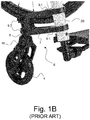
- FIG. 1B is an enlarged view of the photographic illustration of Figure 1A showing in greater detail one of the caster wheel support assemblies 6 (namely the one located on the right-hand side of the wheelchair 1) secured to the front end of the associated frame member 20.
- the caster wheel support assembly 6 comprises a support member 7 having a first section that is secured to the frame member 20 and a second section that is configured to hold a swivel member 8.
- This swivel member 8 is coupled to the relevant caster wheel 4 via a fork element 16 that is freely rotatable about the axis of the swivel member 8.
- Reference numeral 9.1 designates a first pair of bolts that are used to clamp the support member 7 on the relevant frame member 20, while reference numeral 9.2 designates a second pair of bolts that are used to secure the swivel member 8 to the support member 7.
- caster angle designates the angle formed by the caster wheel arrangement in the driving direction
- camber (angle) designates the angle formed by the caster wheel arrangement transversely to the driving direction.
- caster angle and camber should be set to 0°, i.e. the axis of the swivel member 8 about which the fork element 16 is free to rotate should be vertical to ensure optimal behavior and performance.
- Figures 1C and 1D schematically illustrate how caster angle and camber are adjusted with the known caster wheel support assembly 6 depicted in Figure 1B .
- the wheelchair 1 is first placed on a planar surface and the caster wheel 4 is turned transversely to the driving direction (NB: by convention, it will be assumed in the following that the driving direction is a direction that coincides with the x-axis of a Cartesian coordinate system x-y-z as reproduced in the drawings).
- a 90° ruler (such as a triangular ruler) is then placed next to the side of the caster wheel 4, as schematically shown in Figure 1C , to check if the caster wheel 4 is perfectly vertical.
- the bolts 9.2 are loosened to allow the swivel member 8 to be adjusted with respect to the support member 7 (as indicated by the double arrow in Figure 1C ). Adjustment of the position of the swivel member 8 relative to the support member 7 is carried out manually to ensure that the caster wheel 4 is perfectly vertical and the gap with the ruler is eliminated, thereby correcting the caster angle accordingly. Once the adjustment is made, the bolts 9.2 are tightened again to secure the swivel member 8 onto the support member 7.
- FIG 1D which illustrates adjustment of the camber of the caster wheel 4
- the wheelchair 1 is likewise first placed on a planar surface and the caster wheel 4 is turned in this case so as to be aligned with the driving direction.
- a 90° ruler is then placed next to the side of the caster wheel 4, as schematically shown in Figure 1D , to similarly check if the caster wheel 4 is perfectly vertical. If a gap exists between the caster wheel 4 and the ruler (as indicated once again by reference A in Figure 1D ), which is indicative of the fact that adjustment of the camber is required, the bolts 9.1 are loosened in this case to allow the support member 7 to be adjusted (i.e. turned) with respect to the frame member 20 (as indicated by the double arrow in Figure 1D ).
- Adjustment of the position of the support member 7 relative to the frame member 20 is carried out manually to ensure that the caster wheel 4 is perfectly vertical and the gap with the ruler is eliminated, thereby correcting the camber accordingly. Once the adjustment is made, the bolts 9.1 are tightened again to clamp the support member 7 onto the frame member 20.
- a drawback with the aforementioned approach resides in that adjustment of the camber requires loosening of the bolts 9.1 and movement of the entire support member 7 relative to the frame member 20, which may compromise vertical adjustment of the caster wheel support assembly 6 along the frame member 20, and vice versa. This adjustment may furthermore lead to undesired damage to the support member 7 and/or frame member 20 as a result of friction or dirt finding its way between the two components.
- the cross-section of the relevant portion of the frame member 20, where the caster wheel support assembly 6 is secured, is furthermore necessarily circular to allow the support member 7 to be turned relative to the frame member 20 during adjustment, as mentioned above in connection with Figure 1D , which also leads to potential adjustment inaccuracies.
- a general aim of the invention is to provide such a caster wheel support assembly that is easy to adjust on a wheelchair.
- Yet another aim of the invention is to provide such a caster wheel support assembly that allows for a camber of the caster wheel to be adjusted if need be and in a simple manner.
- a further aim of the invention is to provide such a caster wheel support assembly which is of simple construction, is robust and cost-efficient to produce.
- Still another aim of the invention is to provide such a caster wheel support assembly which can be adjusted without causing undesired damage to the wheelchair frame onto which the caster wheel support assembly is secured.
- a caster wheel support assembly for a wheelchair as defined in claim 1, namely a caster wheel support assembly having a first section configured to be securable to a frame member of the wheelchair and a second section configured to hold a swivel member coupled to a caster wheel.
- the caster wheel support assembly comprises a holding member configured to hold a first portion of the swivel member, which first portion extends along a first axis.
- a second portion of the swivel member, which is coupled to the caster wheel extends away from the first portion along a second axis, which second axis forms an angle relative to the first axis.
- the holding member and swivel member are configured such that the first portion of the swivel member is supported by the holding member to selectively allow rotation of the swivel member relative to the holding member about the first axis and thereby cause adjustment of a camber of the caster wheel.
- the holding member is designed as a collet configured to selectively allow :
- the holding member may advantageously comprise a longitudinal opening gap formed along an axial length of the holding member, which longitudinal opening gap is designed to selectively allow clamping or release of the swivel member with respect to the holding member.
- the first portion of the swivel member comprises a head portion that is designed to allow manual rotation of the swivel member about the first axis by means of a tool.
- the camber of the caster wheel is adjustable in a continuous, stepless manner as a result of rotation of the swivel member about the first axis.
- the angle formed between the first and second axes does not exceed 5°, and is preferably of the order of 2°.
- the holding member comprises a guiding aperture extending along the first axis and inside which the first portion of the swivel member is supported.
- the first and second portions of the swivel member may in particular be substantially cylindrical portions coaxial to the first and second axes, respectively, and the first portion of the swivel member may advantageously exhibit a grooved section designed to retain the swivel member inside the guiding aperture, the caster wheel support assembly further comprising a retaining element secured to the holding member, which retaining element cooperates with the grooved section on the first portion of the swivel member.
- this retaining element can also advantageously act as clamping element to selectively clamp the swivel member onto the holding member and prevent rotation of the swivel member relative to the holding member.
- the caster wheel support assembly may be configured to allow adjustment of an angle of inclination of the swivel member forward or rearward in a driving direction.
- the caster wheel support assembly may further comprise a support member with first and second sections acting respectively as the first and second sections of the caster wheel support assembly, the holding member being secured to the second section of the support member.
- the first section of the support member preferably comprises first and second arms each configured to be securable to the frame member.
- the holding member itself is configured to be securable directly to the frame member.
- a wheelchair comprising at least one caster wheel support assembly in accordance with the invention, which caster wheel support assembly is secured to a frame member of the wheelchair.
- the caster wheel support assembly is a caster wheel support assembly comprising the aforementioned support member, and the frame member exhibits a non-circular cross-section where the caster wheel support assembly is secured to the frame member, the first section of the support member being provided with at least one mounting aperture the shape of which substantially matches the non-circular cross-section of the frame member, preventing any rotation of the support member with respect to the frame member.
- the frame member and the support member of the caster wheel support assembly may further be configured such that the support member is slidably adjustable along the frame member.
- the frame member may advantageously be a hydroformed part, preferably made of aluminum.
- the invention will be described in relation to various embodiments of a caster wheel support assembly for attachment to a front end of a wheelchair frame, in a manner similar to the known caster wheel support assembly depicted in Figures 1A to 1D .
- the caster wheel support assembly of the invention is retrofittable on existing wheelchairs, including but not limited to the wheelchair 1 depicted in Figure 1A . It is worth pointing out that the invention is generally applicable to any wheelchair comprising at least one caster wheel support assembly, be it at a front end and/or rear end of the wheelchair.
- FIG 2A is a perspective view of a caster wheel support assembly in accordance with a first embodiment of the present invention, which caster wheel support assembly is generally designated by reference numeral 10.
- the caster wheel support assembly 10 generally has a first section 10A that is configured to be securable to a frame member of a wheelchair and a second section 10B that is configured to hold a swivel member 15 coupled to a caster wheel (not shown in Figure 2A ).
- a caster wheel designated by reference numeral 4', is depicted in the photographic illustration of Figure 6 and can in particular be coupled to the swivel member 15 by means of a fork element 16', in a manner similar to the known caster wheel support assembly 6 of Figures 1A to 1D .
- FIG. 2A A portion of a frame member, designated by reference numeral 20', secured to the first section 10A of the caster wheel support assembly 10, is schematically depicted in dashed lines in Figure 2A for the sake of illustration and explanation.
- the caster wheel support assembly 10 is illustrated in a configuration suitable for mounting on the left-hand side of a wheelchair frame (see also Figure 6 ). It is to be understood that a similar caster wheel support assembly 10 exhibiting a mirrored configuration would be mounted on the right-hand side of the wheelchair frame.
- the overall shape and configuration of the caster wheel support assembly 10 as depicted in Figure 2A is not however limitative and may vary depending on the application and/or on design considerations.
- a Cartesian coordinate system x-y-z is also reproduced in Figure 2A for the sake of identifying the relevant orientation in which the caster wheel support assembly 10 is mounted.
- the x-axis coincides with the relevant driving direction and that the y-axis designates a lateral direction, transversely to the driving direction, while the z-axis designates a direction perpendicular to the plane formed by the x-axis and y-axis.
- the caster wheel support assembly 10 comprises a support member 11 having a first section acting as the aforementioned first section 10A of the caster wheel support assembly 10, which first section is accordingly configured to be securable to the frame member 20'.
- the support member 11 further has a second section acting as the aforementioned second section 10B of the caster wheel support assembly 10, which second section is configured to hold the swivel member 15.
- the first section of the support member 11 may in particular comprise first and second arms 11.1, 11.2 each configured to be securable to the relevant frame member 20', each arm 11.1, 11.2 being provided with a corresponding mounting aperture 120, the shape of which substantially matches the cross-section of the frame member 20'.
- the cross-section of the frame member 20' is advantageously non-circular (see also Figures 2B to 2D ).
- the swivel member 15 is configured to exhibit first and second portions designated by reference numerals 15.1 and 15.2, respectively, which first and second portions 15.1, 15.2 extend along respective axes designated by references A1 and A2 respectively.
- the second portion 15.2 of the swivel member 15 is designed to be coupled to the relevant caster wheel 4', while the first portion 15.1 of the swivel member 15 is held by a holding member 12 that is secured to the second section of the support member 11.
- a shoulder portion 15C is furthermore preferably formed between the first and second portions 15.1, 15.2 to provide support against which the relevant upper portion of the fork element 16' can come in abutment.
- the holding member 12 preferably comprises a substantially cylindrical guiding aperture 12A extending along the first axis A1 and inside which the first portion 15.1 of the swivel member 15 is supported.
- the first and second portions 15.1, 15.2 of the swivel member 15 are preferably substantially cylindrical portions coaxial to the first and second axes A1, A2, respectively.
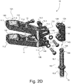
- the first portion 15.1 further exhibits a grooved section 15B designed to retain the swivel member 15 inside the guiding aperture 12A (see Figures 2D , 3 and 4 ).
- the holding member 12 is depicted in transparency to reveal the first portion 15.1 of the swivel member 15 held therein.
- the holding member 12 is preferably secured to the second section of the support member 11 by means of an adjustable retaining mechanism 11.3/11.4/14, which will be described in greater detail hereafter.
- the second section of the support member 11 advantageously exhibits first and second extensions 11.3, 11.4 forming an opening gap 112 between them, which opening gap 112 is dimensioned to receive the holding member 12.
- the holding member 12 is held and secured to the second section of the support member 11 by means of a pair of (upper and lower) retaining elements 14 that are provided in upper and lower portions of the extensions 11.3, 11.4, each provided with corresponding retaining apertures 14A, 14B.
- Corresponding retaining apertures 14C, 14D are likewise formed on the holding member 12 for cooperation with the upper and lower retaining elements 14.
- retaining elements 14 each include a bolt 14.1, a pair of washers 14.2, 14.3 and a nut 14.4 (see Figure 2D ), the holding member 12 being selectively clampable between the extensions 11.3, 11.4 by tightening the retaining elements 14. Conversely, tension can be released by loosening the retaining elements 14.
- retaining elements 14 advantageously fulfill two purposes, namely (i) securing the holding member 12 to the second section of the support member 11 and selectively allowing adjustment of the position of the holding member 12 with respect to the support member 11 to be carried out if need be (leading to a corresponding adjustment of the caster angle in the driving direction as discussed below) and (ii) clamping the swivel member 15 onto the holding member 12 and selectively allowing adjustment of the rotational position of the swivel member 15 with respect to the holding member 12 to be carried out if need be (leading to a corresponding adjustment of the camber of the caster wheel 4 as discussed below).
- the upper retaining element 14 fulfills yet another purpose, namely to interact with the aforementioned grooved section 15B on the first portion 15.1 of the swivel member 15 to retain the swivel member 15 inside the guiding aperture 12A.
- the second portion 15.2 of the swivel member 15 extends away from the first portion 15.1 along the second axis A2, which second axis A2 forms an angle ⁇ relative to the first axis A1.
- this angle ⁇ does not exceed 5°, and is preferably of the order of 2°.
- the holding member 12 and swivel member 15 are configured such that the first portion 15.1 of the swivel member 15 is supported by the holding member 12 to selectively allow rotation of the swivel member 15 relative to the holding member 12 about the first axis A1. Thanks to the particular configuration of the swivel member 15, rotation of the swivel member 15 about the first axis A1 will cause the second portion 15.2 to rotate along a conical trajectory coaxial with the first axis A1. This movement is exploited to carry out adjustment of the camber of the caster wheel 4' that is coupled to the second portion 15.2 of the swivel member 15.
- the holding member 12 is designed as a collet configured to selectively allow :
- the swivel member 15 is released to permit rotation of the swivel member 15 relative to the holding member 12 when adjustment of the camber of the associated caster wheel 4 is required. Once adjustment of the camber has been carried out, the swivel member 15 is clamped onto the holding member 12 to prevent any undesired rotation of the swivel member 15 relative to the holding member 12 under normal operating conditions.
- the holding member 12 comprises a longitudinal opening gap 12B formed along an axial length of the holding member 12 (see e.g. Figures 2B and 2D ), which longitudinal opening gap 12B is designed to selectively allow clamping or release of the swivel member 15 with respect to the holding member 12.
- clamping of the swivel member 15 onto the holding member 12 is achieved thanks to the aforementioned retaining mechanism 11.3/11.4/14, which also acts as clamping mechanism.
- the retaining elements 14 not only act as retaining elements in this example, but also as clamping elements to selectively clamp the swivel member 15 onto the holding member 12.
- the swivel member 15 is prevented from being able to rotate with respect to the holding member 12 by clamping using the retaining elements 14. Loosening the retaining elements 14 allows for the swivel member 15 to be selectively turned about the first axis A1 to carry out adjustments of the camber.
- the first portion 15.1 of the swivel member 15 preferably comprises a head portion 15A that is designed to allow manual rotation of the swivel member 15 about the first axis A1 by means of a tool, such as a screwdriver.
- the head portion 15A is accessible from an upper portion of the caster wheel support assembly 10 (see e.g. Figures 2A , 2C and 3 ).
- the camber of the caster wheel is adjustable in a continuous, stepless manner as a result of rotation of the swivel member 15 about the first axis A1, which is achieved, in the illustrated embodiment, thanks to the overall configuration of the swivel member 15 and holding member 12, which allows for the swivel member 15 to be turned to any desired angular position.
- the caster wheel support assembly 10 is secured, at the first section 10A, to the relevant frame member 20' by means of the support member 11.
- the corresponding first section of the support member 11 is advantageously provided with a clamping mechanism 11.5/11.6/13.
- each end of the first and second arms 11.1, 11.2 that is secured to the frame member 20' is designed as a clamping collar comprising first and second extensions 11.5, 11.6 separated by an opening gap 113 and a clamping element 13 (such as a bolt) that cooperates with both extensions 11.5, 11.6 to selectively allow tightening or loosening of the resulting clamping collar.
- the resulting mounting aperture 120 can accordingly be tightened or loosened around the relevant portion of the frame member 20'.
- the frame member 20' advantageously exhibits a non-circular cross-section where the caster wheel support assembly 10 is secured to the frame member 20', and each mounting aperture 120 exhibits a shape that substantially matches the non-circular cross-section of the frame member 20', thereby preventing any rotation of the support member 11 with respect to the frame member 20'.
- the frame member 20' and the support member 11 are configured such that the support member 11 is slidably adjustable along the frame member 20', namely by loosening the clamping elements 13, moving the support member 11 up or down along the frame member 20', and then tightening again the clamping elements 13 to secure the caster wheel support assembly 10 onto the desired portion of the frame member 20'.
- this adjustment does not in any way affect or compromise the adjustment of the camber or caster angle of the caster wheel arrangement.
- the frame member 20' is a hydroformed part, in particular a hydroformed part made of aluminum. Hydroforming is particularly advantageous in that this technique allows to shape the relevant frame member 20' to exhibit the desired non-circular cross-section.
- Figures 5A to 5C illustrate adjustment of the caster angle forward or rearward in the driving direction in the context of the aforementioned first embodiment of the invention.
- the holding member 12 is held on the second section 10B of the caster wheel support assembly 10, namely on the second section of the support member 11, by means of the retaining mechanism 11.3/11.4/14, which is designed to selectively allow adjustment of the position of the holding member 12 with respect to the support member 11 to be carried out if need be.
- FIGs 7A to 7F are illustrative of a caster wheel support assembly, designated by reference numeral 10*, in accordance with a second embodiment of the present invention.
- This caster wheel support assembly 10* likewise has a first section 10A* configured to be securable to a frame member 20* of a wheelchair and a second section 10B* configured to hold a swivel member 15, which swivel member 15 is designed in the same way as the swivel member 15 used in the first embodiment (see again Figure 4 ).
- the caster wheel support assembly 10* also comprises a holding member 12* configured to hold the first portion 15.1 of the swivel member 15, the head portion 15A thereof being visible in Figures 7A to 7C (see also Figure 7D ).
- the second portion 15.2 of the swivel member 15 (not visible in Figures 7A and 7B - see Figures 7C to 7F ) is likewise coupled to a caster wheel 4* by means of a fork element 16*, the upper end of which comes in abutment with the shoulder portion 15C of the swivel member 15.
- the holding member 12* itself is configured to be securable directly to the frame member 20*.
- the holding member 12* exhibits an extension 12.1* configured to be secured to the frame member 20* by means of an adequate securing mechanism comprising in the instant example a (first) retaining element 14* (not shown in Figures 7A and 7B ) cooperating with a corresponding retaining aperture 14A* provided in an upper portion of the holding member 12* and another retaining element 14** (likewise not shown in Figures 7A and 7B ) cooperating with a corresponding, arc-shaped retaining aperture 14C* provided in extension 12.1*.
- an adequate securing mechanism comprising in the instant example a (first) retaining element 14* (not shown in Figures 7A and 7B ) cooperating with a corresponding retaining aperture 14A* provided in an upper portion of the holding member 12* and another retaining element 14** (likewise not shown in Figures 7A and 7B ) cooperating with a corresponding, arc-shaped retaining aperture 14C* provided
- the caster wheel support assembly 10* is likewise configured to allow adjustment of an angle of inclination of the swivel member 15 forward or rearward in a driving direction, namely by securing the holding member 12* in such a way that a position with respect to the frame member 20* can be adjusted if need be (see Figures 7E and 7F ).
- Figures 7E and 7F illustrate adjustment of the caster angle forward or rearward in the driving direction in the context of the aforementioned second embodiment of the invention.
- the holding member 12* is held on the frame member 20* by means the (upper) retaining element 14* and retaining element 14** in such a way as to selectively allow adjustment of the position of the holding member 12* with respect to the frame member 20* to be carried out if need be.
- This is achieved by configuring the retaining aperture 14C* formed in extension 12.1* to exhibit an arc shape and exploiting the (upper) retaining aperture 14A* and associated retaining element 14* as a pivot axis about which the holding member 12* can pivot after having loosened the retaining elements 14*, 14** as schematically depicted.
- an angle of inclination of the swivel member 15 can be adjusted forward or rearward in a driving direction, leading to a corresponding adjustment of the caster angle.
- retaining elements 14*, 14** each include a bolt 14.1*, resp. 14.1**, a pair of washers 14.2*, 14.3*, resp. 14.2**, 14.3**, and a nut 14.4* (see Figure 7D , the nut associated to bolt 14.1** being not visible in this illustration).
- Figure 7D further shows the presence of an additional adjustment element 14.5** provided in a corresponding retaining aperture 14D* that communicates with the retaining aperture 14C* where the retaining element 14** is provided.
- This additional adjustment element 14.5** is designed to interact with the retaining element 14** to define and adjust the desired caster angle.
- the holding member 12* is likewise designed as a collet configured to selectively allow:
- the holding member 12* to comprise a guiding aperture 12A* extending along the first axis A1 and inside which the first portion 15.1 of the swivel member 15 is supported, as well as a longitudinal opening gap 12B* formed along an axial length of the holding member 12* to selectively allow clamping or release of the swivel member 15 with respect to the holding member 12*, for instance by means of a pair of (upper and lower) retaining and clamping elements 14* cooperating with corresponding retaining apertures 14A*, 14B* provided in the holding member 12*.
- the upper retaining and clamping element 14* likewise cooperates with the grooved section 15B formed in the first portion 15.1 of the swivel member 15 to ensure that the swivel member is held inside the guiding aperture 12A* as long as the upper retaining and clamping element 14* remains in place.
- Adjustment of the camber is carried out in the same way as in the context of the first embodiment, namely by loosening the retaining and clamping elements 14*, turning the swivel member 15 by means of a tool, such as a screwdriver, to adjust the camber to the desired setting, and retightening the retaining and clamping elements 14* after the camber has been adjusted.
- the swivel member used in the context of the embodiments described above exhibits a substantially cylindrical first portion and is rotatable over 360°
- the embodiments disclosed herein show wheelchairs equipped with a pair of front caster wheels, the invention is generally applicable to any wheelchair comprising one or more caster wheel support assemblies provided at the front and/or rear end of the wheelchair.
Priority Applications (2)
| Application Number | Priority Date | Filing Date | Title |
|---|---|---|---|
| EP18192870.6A EP3620146B1 (de) | 2018-09-06 | 2018-09-06 | Lenkradstützeinrichtung für einen rollstuhl und rollstuhl damit |
| US16/562,512 US11203230B2 (en) | 2018-09-06 | 2019-09-06 | Caster wheel support assembly for a wheelchair and wheelchair comprising the same |
Applications Claiming Priority (1)
| Application Number | Priority Date | Filing Date | Title |
|---|---|---|---|
| EP18192870.6A EP3620146B1 (de) | 2018-09-06 | 2018-09-06 | Lenkradstützeinrichtung für einen rollstuhl und rollstuhl damit |
Publications (2)
| Publication Number | Publication Date |
|---|---|
| EP3620146A1 true EP3620146A1 (de) | 2020-03-11 |
| EP3620146B1 EP3620146B1 (de) | 2023-02-15 |
Family
ID=63524110
Family Applications (1)
| Application Number | Title | Priority Date | Filing Date |
|---|---|---|---|
| EP18192870.6A Active EP3620146B1 (de) | 2018-09-06 | 2018-09-06 | Lenkradstützeinrichtung für einen rollstuhl und rollstuhl damit |
Country Status (2)
| Country | Link |
|---|---|
| US (1) | US11203230B2 (de) |
| EP (1) | EP3620146B1 (de) |
Families Citing this family (3)
| Publication number | Priority date | Publication date | Assignee | Title |
|---|---|---|---|---|
| EP3620146B1 (de) * | 2018-09-06 | 2023-02-15 | Invacare International GmbH | Lenkradstützeinrichtung für einen rollstuhl und rollstuhl damit |
| US11865054B1 (en) * | 2020-02-18 | 2024-01-09 | Stephen C Golden, Jr. | Wheelchair mount apparatus |
| NL2026638B1 (en) * | 2020-10-07 | 2022-06-08 | Univ Delft Tech | A movable vehicle |
Citations (12)
| Publication number | Priority date | Publication date | Assignee | Title |
|---|---|---|---|---|
| US518A (en) | 1837-12-15 | Improvement in horizontal water-wheels | ||
| US7520A (en) | 1850-07-22 | Improvement in machines for raking-and binding grain | ||
| DE29704125U1 (de) * | 1997-03-07 | 1997-07-10 | Sopur Medizintechnik Gmbh | Rollstuhl |
| DE29817702U1 (de) | 1998-10-05 | 1999-01-07 | Sopur Medizintechnik Gmbh | Rollstuhl |
| JP2003180758A (ja) * | 2001-12-17 | 2003-07-02 | Ox Engineering:Kk | キャスタ連結システム |
| WO2003104028A2 (en) | 2002-06-05 | 2003-12-18 | Sunrise Medical Hhg Inc. | Adjustable wheel assembly |
| EP1454764A1 (de) | 2003-03-04 | 2004-09-08 | Invacare AG | Vorderradträger für einen Rollstuhl |
| EP1872761A1 (de) | 2006-06-30 | 2008-01-02 | Invacare International Sàrl | Winkelverstellvorrichtung einer Schwenkrolle für einen Rollstuhl |
| WO2012131642A1 (en) | 2011-04-01 | 2012-10-04 | Invacare International Sàrl | Wheelchair with adjustment of the castor wheel swivel axis |
| WO2013093874A1 (en) | 2011-12-21 | 2013-06-27 | Invacare International Sàrl | Easily dissociable wheelchair |
| WO2014057306A1 (en) | 2012-10-09 | 2014-04-17 | Invacare International Sàrl | Quick release device for a wheelchair |
| WO2016042444A1 (en) | 2014-09-19 | 2016-03-24 | Invacare International Sàrl | Foldable wheelchair having a stiffer construction |
Family Cites Families (10)
| Publication number | Priority date | Publication date | Assignee | Title |
|---|---|---|---|---|
| JPH0735762Y2 (ja) * | 1984-12-30 | 1995-08-16 | 日産自動車株式会社 | 旋回キヤスタ |
| US5060962A (en) * | 1990-05-21 | 1991-10-29 | Everest & Jennings, Inc. | Rear wheel camber sleeve assembly for a wheelchair |
| DE9113058U1 (de) * | 1991-10-21 | 1991-12-19 | Meyra Wilhelm Meyer Gmbh & Co Kg, 4925 Kalletal, De | |
| US5360224A (en) * | 1991-11-08 | 1994-11-01 | Medical Composite Technology, Inc. | Wheelchair frame assembly and components for use thereon |
| US5590893A (en) * | 1994-12-28 | 1997-01-07 | No Limit Designs, Inc. | Wheelchair frame assembly |
| US7231689B2 (en) * | 2002-06-05 | 2007-06-19 | Sunrise Medical Hhg Inc. | Adjustable wheel assembly |
| US7520518B2 (en) | 2004-10-25 | 2009-04-21 | Invacare Corporation | Wheelchair |
| US8002300B2 (en) * | 2007-09-28 | 2011-08-23 | Tisport, Llc | Rear wheel mounting assembly for a wheelchair |
| US10085903B1 (en) * | 2016-07-14 | 2018-10-02 | Ki Mobility | Angle adjustment assembly |
| EP3620146B1 (de) * | 2018-09-06 | 2023-02-15 | Invacare International GmbH | Lenkradstützeinrichtung für einen rollstuhl und rollstuhl damit |
-
2018
- 2018-09-06 EP EP18192870.6A patent/EP3620146B1/de active Active
-
2019
- 2019-09-06 US US16/562,512 patent/US11203230B2/en active Active
Patent Citations (13)
| Publication number | Priority date | Publication date | Assignee | Title |
|---|---|---|---|---|
| US7520A (en) | 1850-07-22 | Improvement in machines for raking-and binding grain | ||
| US518A (en) | 1837-12-15 | Improvement in horizontal water-wheels | ||
| DE29704125U1 (de) * | 1997-03-07 | 1997-07-10 | Sopur Medizintechnik Gmbh | Rollstuhl |
| DE29817702U1 (de) | 1998-10-05 | 1999-01-07 | Sopur Medizintechnik Gmbh | Rollstuhl |
| JP2003180758A (ja) * | 2001-12-17 | 2003-07-02 | Ox Engineering:Kk | キャスタ連結システム |
| US7353566B2 (en) | 2002-06-05 | 2008-04-08 | Sunrise Medical Hhg Inc. | Adjustable wheel assembly |
| WO2003104028A2 (en) | 2002-06-05 | 2003-12-18 | Sunrise Medical Hhg Inc. | Adjustable wheel assembly |
| EP1454764A1 (de) | 2003-03-04 | 2004-09-08 | Invacare AG | Vorderradträger für einen Rollstuhl |
| EP1872761A1 (de) | 2006-06-30 | 2008-01-02 | Invacare International Sàrl | Winkelverstellvorrichtung einer Schwenkrolle für einen Rollstuhl |
| WO2012131642A1 (en) | 2011-04-01 | 2012-10-04 | Invacare International Sàrl | Wheelchair with adjustment of the castor wheel swivel axis |
| WO2013093874A1 (en) | 2011-12-21 | 2013-06-27 | Invacare International Sàrl | Easily dissociable wheelchair |
| WO2014057306A1 (en) | 2012-10-09 | 2014-04-17 | Invacare International Sàrl | Quick release device for a wheelchair |
| WO2016042444A1 (en) | 2014-09-19 | 2016-03-24 | Invacare International Sàrl | Foldable wheelchair having a stiffer construction |
Also Published As
| Publication number | Publication date |
|---|---|
| EP3620146B1 (de) | 2023-02-15 |
| US20200079153A1 (en) | 2020-03-12 |
| US11203230B2 (en) | 2021-12-21 |
Similar Documents
| Publication | Publication Date | Title |
|---|---|---|
| US11203230B2 (en) | Caster wheel support assembly for a wheelchair and wheelchair comprising the same | |
| EP0966383B1 (de) | Schleppvorrichtung für fahrräder | |
| US7438306B2 (en) | Motorcycle rake and trail adjuster | |
| CN101850785B (zh) | 转向装置 | |
| CA2471149A1 (en) | Carrier for attachment to a bicycle | |
| US9801766B1 (en) | Multi-adjustable wheelchair and frame therefor | |
| EP0816205A3 (de) | Lenksäuleneinheit für Fahrzeug | |
| EP2686225A1 (de) | Modulares greifersystem für fahrzeugkarosserieteile | |
| US10421514B2 (en) | Rack for bicycle and bicycle with rack | |
| US5342015A (en) | Apparatus for mounting rear view mirrors on a tractor | |
| EP2694008B1 (de) | Rollstuhl mit einstellung der rollenschwenkachse | |
| US20040000770A1 (en) | One-sides sprung arm of a bicycle front wheel | |
| JP6043014B1 (ja) | 自転車用キャリア | |
| TW201922552A (zh) | 自行車支架安裝用配接器及具備其之兩足支架 | |
| JP2016055774A (ja) | 自転車用バックミラー装置 | |
| CN206187215U (zh) | 一种适用于倒三轮车的前两轮转向装置 | |
| GB2472887A (en) | Folding bicycle with latch for holding in folded position | |
| CN208895962U (zh) | 辅助定位装置 | |
| US20220296442A1 (en) | Anti-tip wheelchair | |
| JP2001018809A (ja) | 自動チルトテレスコピック式ステアリング装置 | |
| JP3107311U (ja) | 自転車用傘取り付け器具と取り付け位置 | |
| CN110979534A (zh) | 一种可折叠两轮车 | |
| JP2001001728A (ja) | 車両の懸架装置 | |
| JP2009035183A (ja) | アシストグリップ | |
| EP2399816A1 (de) | Anbauwagen für Fahrräder |
Legal Events
| Date | Code | Title | Description |
|---|---|---|---|
| PUAI | Public reference made under article 153(3) epc to a published international application that has entered the european phase |
Free format text: ORIGINAL CODE: 0009012 |
|
| STAA | Information on the status of an ep patent application or granted ep patent |
Free format text: STATUS: THE APPLICATION HAS BEEN PUBLISHED |
|
| AK | Designated contracting states |
Kind code of ref document: A1 Designated state(s): AL AT BE BG CH CY CZ DE DK EE ES FI FR GB GR HR HU IE IS IT LI LT LU LV MC MK MT NL NO PL PT RO RS SE SI SK SM TR |
|
| AX | Request for extension of the european patent |
Extension state: BA ME |
|
| STAA | Information on the status of an ep patent application or granted ep patent |
Free format text: STATUS: REQUEST FOR EXAMINATION WAS MADE |
|
| 17P | Request for examination filed |
Effective date: 20200904 |
|
| RBV | Designated contracting states (corrected) |
Designated state(s): AL AT BE BG CH CY CZ DE DK EE ES FI FR GB GR HR HU IE IS IT LI LT LU LV MC MK MT NL NO PL PT RO RS SE SI SK SM TR |
|
| GRAP | Despatch of communication of intention to grant a patent |
Free format text: ORIGINAL CODE: EPIDOSNIGR1 |
|
| STAA | Information on the status of an ep patent application or granted ep patent |
Free format text: STATUS: GRANT OF PATENT IS INTENDED |
|
| INTG | Intention to grant announced |
Effective date: 20220824 |
|
| GRAS | Grant fee paid |
Free format text: ORIGINAL CODE: EPIDOSNIGR3 |
|
| GRAA | (expected) grant |
Free format text: ORIGINAL CODE: 0009210 |
|
| STAA | Information on the status of an ep patent application or granted ep patent |
Free format text: STATUS: THE PATENT HAS BEEN GRANTED |
|
| AK | Designated contracting states |
Kind code of ref document: B1 Designated state(s): AL AT BE BG CH CY CZ DE DK EE ES FI FR GB GR HR HU IE IS IT LI LT LU LV MC MK MT NL NO PL PT RO RS SE SI SK SM TR |
|
| REG | Reference to a national code |
Ref country code: CH Ref legal event code: EP Ref country code: GB Ref legal event code: FG4D |
|
| REG | Reference to a national code |
Ref country code: DE Ref legal event code: R096 Ref document number: 602018046104 Country of ref document: DE |
|
| REG | Reference to a national code |
Ref country code: AT Ref legal event code: REF Ref document number: 1547879 Country of ref document: AT Kind code of ref document: T Effective date: 20230315 Ref country code: IE Ref legal event code: FG4D |
|
| REG | Reference to a national code |
Ref country code: LT Ref legal event code: MG9D |
|
| REG | Reference to a national code |
Ref country code: NL Ref legal event code: MP Effective date: 20230215 |
|
| REG | Reference to a national code |
Ref country code: AT Ref legal event code: MK05 Ref document number: 1547879 Country of ref document: AT Kind code of ref document: T Effective date: 20230215 |
|
| PG25 | Lapsed in a contracting state [announced via postgrant information from national office to epo] |
Ref country code: RS Free format text: LAPSE BECAUSE OF FAILURE TO SUBMIT A TRANSLATION OF THE DESCRIPTION OR TO PAY THE FEE WITHIN THE PRESCRIBED TIME-LIMIT Effective date: 20230215 Ref country code: PT Free format text: LAPSE BECAUSE OF FAILURE TO SUBMIT A TRANSLATION OF THE DESCRIPTION OR TO PAY THE FEE WITHIN THE PRESCRIBED TIME-LIMIT Effective date: 20230615 Ref country code: NO Free format text: LAPSE BECAUSE OF FAILURE TO SUBMIT A TRANSLATION OF THE DESCRIPTION OR TO PAY THE FEE WITHIN THE PRESCRIBED TIME-LIMIT Effective date: 20230515 Ref country code: NL Free format text: LAPSE BECAUSE OF FAILURE TO SUBMIT A TRANSLATION OF THE DESCRIPTION OR TO PAY THE FEE WITHIN THE PRESCRIBED TIME-LIMIT Effective date: 20230215 Ref country code: LV Free format text: LAPSE BECAUSE OF FAILURE TO SUBMIT A TRANSLATION OF THE DESCRIPTION OR TO PAY THE FEE WITHIN THE PRESCRIBED TIME-LIMIT Effective date: 20230215 Ref country code: LT Free format text: LAPSE BECAUSE OF FAILURE TO SUBMIT A TRANSLATION OF THE DESCRIPTION OR TO PAY THE FEE WITHIN THE PRESCRIBED TIME-LIMIT Effective date: 20230215 Ref country code: HR Free format text: LAPSE BECAUSE OF FAILURE TO SUBMIT A TRANSLATION OF THE DESCRIPTION OR TO PAY THE FEE WITHIN THE PRESCRIBED TIME-LIMIT Effective date: 20230215 Ref country code: ES Free format text: LAPSE BECAUSE OF FAILURE TO SUBMIT A TRANSLATION OF THE DESCRIPTION OR TO PAY THE FEE WITHIN THE PRESCRIBED TIME-LIMIT Effective date: 20230215 Ref country code: AT Free format text: LAPSE BECAUSE OF FAILURE TO SUBMIT A TRANSLATION OF THE DESCRIPTION OR TO PAY THE FEE WITHIN THE PRESCRIBED TIME-LIMIT Effective date: 20230215 |
|
| PG25 | Lapsed in a contracting state [announced via postgrant information from national office to epo] |
Ref country code: SE Free format text: LAPSE BECAUSE OF FAILURE TO SUBMIT A TRANSLATION OF THE DESCRIPTION OR TO PAY THE FEE WITHIN THE PRESCRIBED TIME-LIMIT Effective date: 20230215 Ref country code: PL Free format text: LAPSE BECAUSE OF FAILURE TO SUBMIT A TRANSLATION OF THE DESCRIPTION OR TO PAY THE FEE WITHIN THE PRESCRIBED TIME-LIMIT Effective date: 20230215 Ref country code: IS Free format text: LAPSE BECAUSE OF FAILURE TO SUBMIT A TRANSLATION OF THE DESCRIPTION OR TO PAY THE FEE WITHIN THE PRESCRIBED TIME-LIMIT Effective date: 20230615 Ref country code: GR Free format text: LAPSE BECAUSE OF FAILURE TO SUBMIT A TRANSLATION OF THE DESCRIPTION OR TO PAY THE FEE WITHIN THE PRESCRIBED TIME-LIMIT Effective date: 20230516 Ref country code: FI Free format text: LAPSE BECAUSE OF FAILURE TO SUBMIT A TRANSLATION OF THE DESCRIPTION OR TO PAY THE FEE WITHIN THE PRESCRIBED TIME-LIMIT Effective date: 20230215 |
|
| PG25 | Lapsed in a contracting state [announced via postgrant information from national office to epo] |
Ref country code: SM Free format text: LAPSE BECAUSE OF FAILURE TO SUBMIT A TRANSLATION OF THE DESCRIPTION OR TO PAY THE FEE WITHIN THE PRESCRIBED TIME-LIMIT Effective date: 20230215 Ref country code: RO Free format text: LAPSE BECAUSE OF FAILURE TO SUBMIT A TRANSLATION OF THE DESCRIPTION OR TO PAY THE FEE WITHIN THE PRESCRIBED TIME-LIMIT Effective date: 20230215 Ref country code: EE Free format text: LAPSE BECAUSE OF FAILURE TO SUBMIT A TRANSLATION OF THE DESCRIPTION OR TO PAY THE FEE WITHIN THE PRESCRIBED TIME-LIMIT Effective date: 20230215 Ref country code: DK Free format text: LAPSE BECAUSE OF FAILURE TO SUBMIT A TRANSLATION OF THE DESCRIPTION OR TO PAY THE FEE WITHIN THE PRESCRIBED TIME-LIMIT Effective date: 20230215 Ref country code: CZ Free format text: LAPSE BECAUSE OF FAILURE TO SUBMIT A TRANSLATION OF THE DESCRIPTION OR TO PAY THE FEE WITHIN THE PRESCRIBED TIME-LIMIT Effective date: 20230215 |
|
| PGFP | Annual fee paid to national office [announced via postgrant information from national office to epo] |
Ref country code: GB Payment date: 20230920 Year of fee payment: 6 |
|
| REG | Reference to a national code |
Ref country code: DE Ref legal event code: R097 Ref document number: 602018046104 Country of ref document: DE |
|
| PG25 | Lapsed in a contracting state [announced via postgrant information from national office to epo] |
Ref country code: SK Free format text: LAPSE BECAUSE OF FAILURE TO SUBMIT A TRANSLATION OF THE DESCRIPTION OR TO PAY THE FEE WITHIN THE PRESCRIBED TIME-LIMIT Effective date: 20230215 |
|
| PGFP | Annual fee paid to national office [announced via postgrant information from national office to epo] |
Ref country code: FR Payment date: 20230928 Year of fee payment: 6 Ref country code: DE Payment date: 20230920 Year of fee payment: 6 |
|
| PLBE | No opposition filed within time limit |
Free format text: ORIGINAL CODE: 0009261 |
|
| STAA | Information on the status of an ep patent application or granted ep patent |
Free format text: STATUS: NO OPPOSITION FILED WITHIN TIME LIMIT |
|
| 26N | No opposition filed |
Effective date: 20231116 |
|
| PG25 | Lapsed in a contracting state [announced via postgrant information from national office to epo] |
Ref country code: SI Free format text: LAPSE BECAUSE OF FAILURE TO SUBMIT A TRANSLATION OF THE DESCRIPTION OR TO PAY THE FEE WITHIN THE PRESCRIBED TIME-LIMIT Effective date: 20230215 |