EP3619119B2 - Verfahren zum polstern von gegenständen in einem behälter, sowie vorrichtung zum polstern von gegenständen in einem behälter - Google Patents
Verfahren zum polstern von gegenständen in einem behälter, sowie vorrichtung zum polstern von gegenständen in einem behälter Download PDFInfo
- Publication number
- EP3619119B2 EP3619119B2 EP18721761.7A EP18721761A EP3619119B2 EP 3619119 B2 EP3619119 B2 EP 3619119B2 EP 18721761 A EP18721761 A EP 18721761A EP 3619119 B2 EP3619119 B2 EP 3619119B2
- Authority
- EP
- European Patent Office
- Prior art keywords
- container
- cushioning
- characterizing
- cushioning means
- transported
- Prior art date
- Legal status (The legal status is an assumption and is not a legal conclusion. Google has not performed a legal analysis and makes no representation as to the accuracy of the status listed.)
- Active
Links
Images
Classifications
-
- B—PERFORMING OPERATIONS; TRANSPORTING
- B65—CONVEYING; PACKING; STORING; HANDLING THIN OR FILAMENTARY MATERIAL
- B65B—MACHINES, APPARATUS OR DEVICES FOR, OR METHODS OF, PACKAGING ARTICLES OR MATERIALS; UNPACKING
- B65B55/00—Preserving, protecting or purifying packages or package contents in association with packaging
- B65B55/20—Embedding contents in shock-absorbing media, e.g. plastic foam, granular material
-
- B—PERFORMING OPERATIONS; TRANSPORTING
- B65—CONVEYING; PACKING; STORING; HANDLING THIN OR FILAMENTARY MATERIAL
- B65B—MACHINES, APPARATUS OR DEVICES FOR, OR METHODS OF, PACKAGING ARTICLES OR MATERIALS; UNPACKING
- B65B57/00—Automatic control, checking, warning, or safety devices
- B65B57/10—Automatic control, checking, warning, or safety devices responsive to absence, presence, abnormal feed, or misplacement of articles or materials to be packaged
- B65B57/12—Automatic control, checking, warning, or safety devices responsive to absence, presence, abnormal feed, or misplacement of articles or materials to be packaged and operating to control, or stop, the feed of wrapping materials, containers, or packages
-
- B—PERFORMING OPERATIONS; TRANSPORTING
- B65—CONVEYING; PACKING; STORING; HANDLING THIN OR FILAMENTARY MATERIAL
- B65B—MACHINES, APPARATUS OR DEVICES FOR, OR METHODS OF, PACKAGING ARTICLES OR MATERIALS; UNPACKING
- B65B61/00—Auxiliary devices, not otherwise provided for, for operating on sheets, blanks, webs, binding material, containers or packages
- B65B61/20—Auxiliary devices, not otherwise provided for, for operating on sheets, blanks, webs, binding material, containers or packages for adding cards, coupons or other inserts to package contents
- B65B61/22—Auxiliary devices, not otherwise provided for, for operating on sheets, blanks, webs, binding material, containers or packages for adding cards, coupons or other inserts to package contents for placing protecting sheets, plugs, or wads over contents, e.g. cotton-wool in bottles of pills
-
- B—PERFORMING OPERATIONS; TRANSPORTING
- B65—CONVEYING; PACKING; STORING; HANDLING THIN OR FILAMENTARY MATERIAL
- B65B—MACHINES, APPARATUS OR DEVICES FOR, OR METHODS OF, PACKAGING ARTICLES OR MATERIALS; UNPACKING
- B65B2210/00—Specific aspects of the packaging machine
- B65B2210/04—Customised on demand packaging by determining a specific characteristic, e.g. shape or height, of articles or material to be packaged and selecting, creating or adapting a packaging accordingly, e.g. making a carton starting from web material
Definitions
- the present invention relates to a method for cushioning objects in a container according to the preamble of claim 1.
- a cushioning agent for example, from the EN 10 2012 222 805 B3 It is known to produce a cushioning agent from a web-shaped starting material, for example a flat paper strip, by crumpling it.
- various technologies are known on the market with which a cushioning agent is produced and introduced into a container in which objects are placed, depending on a residual empty volume.
- One example of this is the EP 1 556 278 B1 .
- the US 2011/016833 A1 discloses a system for packing objects in a container and a controlled release of cushioning material. The amount of cushioning material released depends on certain values.
- the WO 2008/146111 A1 describes the release of upholstery material depending on the weight of the upholstery material.
- the object of the present invention is to provide a method for cushioning objects in a container that is as simple and thus inexpensive as possible.
- a method for cushioning objects in a container comprises the following steps: detecting and/or determining a quantity characterizing a residual empty volume of the container by means of at least one sensor and automatically producing at least one cushioning agent depending on the quantity characterizing the residual empty volume of the container. It is further proposed that a cushioning agent is only produced if this results from a comparison of the quantity characterizing the residual empty volume of the container with a limit value, i.e. if this, for example, reaches and/or exceeds the limit value or, in another constellation, does not reach the limit value or falls below it. It is preferred that the cushioning agent has predetermined dimensions that are independent of the quantity characterizing the residual empty volume of the container.
- the method according to the invention has the advantage that a cushioning agent is only produced if it has been determined that the remaining empty volume is so large that it justifies the production and insertion of a cushioning agent.
- the production of a cushioning agent is therefore based on a yes/no decision and not on a complex evaluation process. This avoids unnecessary production of a cushioning agent. This in turn saves time and resources and therefore also costs.
- the cushioning material is transported into the container by gravity. This eliminates the need for a complex transport device with a separate drive, which in turn saves costs.
- the cushioning material be transported along a chute into the container. This allows the cushioning material to be fed precisely and reliably into the remaining empty volume in the container, while at the same time being cost-effective and highly reliable, as no drive means are required.
- the cushioning material is transported into the container by means of a robot. This enables the cushioning material to be placed very precisely in the container. The reliability of the placement of the cushioning material in the container is also increased.
- the invention is characterized in that the size characterizing the remaining empty volume of the container includes or is an average height within the interior of the container or in a section within the interior of the container. According to the invention, no complex determination of a contour of the objects present in the container is carried out, nor is any complex determination of the geometric distribution of the remaining empty volume in the container. Instead, only an average height of the objects in the container is determined, which allows the remaining empty volume in the container to be characterized very well. The average height is calculated from the arithmetic mean of the maximum heights recorded in certain sectors within the interior of the container. To estimate the remaining empty volume or the size characterizing the remaining empty volume, it is also useful to know the height of the container.
- variable characterizing the remaining empty volume of the container is determined using the signal from a sensor, in particular a height sensor.
- a sensor can be, for example, a sensor that works tactilely or a contactless sensor, for example an image capture device, an ultrasonic sensor and/or a barcode scanner.
- the barcode scanner can, for example, scan a barcode attached to the container either on its outside or on its inside.
- the information encoded in the barcode can, for example, be a variable characterizing the empty volume of the container (for example the height of the empty volume of the container) and the heights of the objects placed in the container according to a packing list.
- the barcode can also explicitly contain the variable characterizing the remaining empty volume, or even the yes/no decision as to whether a cushioning agent should be produced or not.
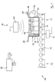
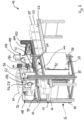
- a device for cushioning objects in a container carries in the Figures 1 and 2 overall the reference number 10. It comprises a first transport device 12, which in the present case comprises a roller conveyor with individual rollers 14 arranged parallel to one another. For reasons of clarity, Figure 1 only one of these rollers is provided with the reference number 14. These rollers 14 are kinematically connected to one another in that they can be set in rotation by a common drive 16.
- the first transport device 12 belongs to a first station 18 of the device 10, in which a value characterizing a residual empty volume of a container is recorded.
- a corresponding container carries Figure 1 the reference number 20. It is used for sending objects that are arranged in an interior of the container 20 and bear the reference numbers 22a, 22b and 22c.
- the container comprises a base 24, side walls 26, and movable closure flaps 28.
- the container is typically made of cardboard.
- a height of an empty volume of the container 20 bears the reference number 30.
- An average height within the interior of the container 20 bears the reference number 32.
- the average height 32 refers to a height which, on the one hand, takes into account the heights of the objects 22a-c, but which also takes into account the size of the area of the base 24 which is not occupied by the objects 22a-c.
- the average height is formed from the arithmetic mean of the maximum heights recorded in certain sectors (for example the 4 quadrants) within the interior of the container 20.
- a sensor 34 is initially provided, which is arranged above the container 20.
- the sensor 34 can be an image capture device, for example a camera, an ultrasonic sensor or a tactile sensor. It goes without saying that the actual height value is determined by a distance measurement, which is set in relation to the distance from the floor 24 of the container 20.
- a sensor 36 in the form of a barcode scanner is provided. This can be used to read a barcode 37 arranged on the outside of a side wall 26 of the container 20.
- One of the pieces of information contained in the barcode 37 is the said height 30.
- the height 30 of the empty volume of the container 20 is also determined by the sensor 34 or by another lateral sensor.
- control device 38 This receives signals, for example, from the two sensors 34 and 36 and controls, for example, the drive 16 of the first transport device 12.
- a residual empty volume 40 is shown in dotted lines. This is the volume within the interior of the container 20 which results from the difference between the height 30 of the empty volume and the average height 32.
- the average height 32 is determined by the control device 38 in accordance with the basic calculation options described above. It can be seen that the average height 32 is a value which characterizes the residual empty volume 40 in the interior of the container 20, insofar as it is at least related to the residual empty volume 40.
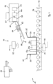
- FIG 1 In the lower left area a small part of a second transport device 42 is shown. As can be seen from Figure 2 As can be seen, this belongs to a second station 44 of the device 10. Like the first transport device 12, the second transport device 42 also comprises a plurality of driven rollers 46 arranged parallel to one another, of which, for reasons of clarity, Figure 2 only one is designated with a reference number. The common drive of these rollers 46 is in Figure 2 designated 48.
- the second station 44 includes a sensor 50, which is shown here above the second transport device 42. In principle, however, an arrangement to the side or even below the second transport device 42 is also conceivable.
- the sensor 50 detects the presence of the container 20 in the second station 44.
- the sensor 50 can be an ultrasonic sensor or a light barrier, for example.
- the second station 44 also includes a means 52 for producing a cushioning agent.
- the means 52 is designed here as a device with which a cushioning agent is produced from a web-shaped starting material, for example a paper material, by crumpling.
- the means 52 has a paper supply 54, which can be paper rolled up on a roll or paper folded in a zigzag pattern in a tray.
- a crumpling device 56 conveys the web-shaped starting material and compresses it in its longitudinal direction.
- the crumpling device 56 has two pairs of rollers (not shown) arranged one behind the other in the conveying direction 57, between which the paper is conveyed, with the rear pair of rollers, as seen in the conveying direction, conveying the paper at a lower speed than the front pair of rollers, as seen in the conveying direction.
- the paper is compressed or crumpled from the first pair of rollers to the second pair of rollers.
- a separating device 58 is arranged behind the crumpling device 56, as seen in the conveying direction 57, which separates a single cushioning means (also called a "cushion pad” or “cushion cushion”) from the crumpled web-shaped material.
- This separation can be carried out, for example, by cutting or tearing, whereby in one case the separating device comprises a cutting means and in the other case a tearing means.
- the discrete cushioning agent produced in this way passes through an outlet 60 onto a chute 62 arranged at an angle to a horizontal.
- the inclination of the chute is so great that a cushioning agent lying on the chute 62 (in Figure 2 designated by the reference numeral 64) slides downwards due to gravity along a longitudinal direction of the slide 62 and, after leaving the slide 62, falls at the lower end into the container 20 arranged below the lower end of the slide 62. This is in Figure 2 indicated by corresponding arrows 66.
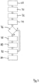
- the method begins in a start block 68. Following this, in a block 70, the container 20 is transported to the first station 18 by the drive 16 being controlled accordingly by the control device 38. As soon as the container 20 is in the first station 18 (which can also be determined by the sensor 34, for example), the first transport device 12 is stopped. Now, in a block 72, the barcode 37 is read out using the sensor 36 and a corresponding signal is transmitted to the control device 38. In a block 74, the height at different points in the interior of the container 20 is determined using the sensor 34, and corresponding signals are transmitted to the control device 38.
- the control device 38 determines an average height 32 which, as already mentioned above, in conjunction with the height 30 of the empty volume of the container 20 transmitted via the sensor 36, is a value characterizing the remaining empty volume 40 of the container 20.
- the average height 32 is then compared with a limit value in a block 76. The further course of the method depends on the result of this comparison.
- the container 20 is transported to the second station 44 in a block 78.
- the two transport devices 12 and 42 are put into operation accordingly by the control device 38.
- the first transport device 12 can be stopped or driven independently of the second transport device 42 to transport another container 20 to the first station 18.
- the container 20 is in the second station 44, which is detected by the sensor 50, in a block 80 of the control device 38 sets the agent 52 in motion and produces the cushioning agent 64.
- the production of the cushioning means 64 can also depend on information that was transmitted to the control device 38 by reading the barcode 37 on the container 20.
- this information can contain information about the size of the container 20, so that a larger or smaller cushioning means 64 is produced depending on the case.
- the cushioning means 64 has predetermined dimensions that are independent of the size characterizing the remaining empty volume of the container (in this case, the average height 32).
- the control device 38 comprises a timer which allows a certain amount of time to elapse after the production of the cushioning material 64 before the control device 38 initiates further transport of the container 20 to a subsequent station (not shown) in a block 82 by controlling the drive 48 accordingly. This time limit ensures that the cushioning material 64 produced has reached the container 20 via the chute 62 before the container 20 is transported out of the second station 44.
- the method ends in a block 84.
- a yes/no decision is made in decision block 76, which in the present embodiment means that either a cushioning agent 64 is produced and placed in the container 20, or that a cushioning agent 64 is not produced and thus not placed in the container 20. It is understood that the previously used term "one" cushioning agent 64 does not mean that only a single cushioning agent 64 is produced. It is understood that a multi-part cushioning agent 64 can also be produced in block 80.
- the cushioning material 64 is transported along a slide 62 into the container 20.
- other devices for transporting the cushioning material into the container are also conceivable.
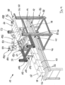
- a robot could also be used for this purpose, as can be seen from the Figures 4 and 5 which show a second embodiment of a device 10 for cushioning objects in a container.
- those elements and areas which have equivalent functions to the embodiment of the Figures 1-3 have the same reference symbols. They are not normally explained in detail again.
- a support structure 86 made of standard profiles can be seen, which comprises a total of four vertical stands 88. This supports a frame 90 above the first transport device 12 and the second transport device 42, which in turn supports a grid-like holding plate 92.
- two sensors are arranged with the function that the sensor 34 in the embodiment of the Figures 1 and 2 has. Seen in the conveying direction of the two transport devices 12 and 42, these two sensors are arranged one behind the other. Above the two sensors, on the holding plate 92, there is a receiving channel 94, made for example from sheet metal, in which a crumpled, tubular cushioning means 64 is deposited when it has been produced by the means 52 for producing the cushioning means 64, which is also arranged on the holding plate 92.
- Two of the vertical posts 88 of the support structure 86 also carry a buffer shelf 96 in which produced but not yet required cushioning materials 64 can be temporarily stored. From the Figures 4 and 5 It is clearly visible that the cushioning means 64 stored in the buffer shelf 96 are all identical. Unlike the embodiment of the Figures 1 and 2 the paper supply is not shown here. Only a storage plate 98 is shown, on which a stack of zigzag-folded paper material in web form can be stored - as mentioned above, not shown. As already mentioned, the paper material in web form is double-layered, so that it can be formed into the crumpled, tubular cushioning means 64 in the means 52.
- the cushioning means 64 in the embodiment of the Figures 4 and 5 not via a slide into the container 20, but by means of a robot 100.
- Such robots are also referred to as "pick-and-place robots".
- the robot 100 comprises a base 102, which is screwed onto the frame 90 above a stand 88.
- a touch-sensitive screen 104 (touchscreen) is arranged on the base 102, with which the robot 100 can be programmed.
- the robot 100 has a robot arm 106 provided with several joints, which is provided with a gripping device 108 at its protruding end. It is understood that the robot is also connected to the control device 38 and is controlled by it.
- the device 10 also includes a hold-down device 110.
- This comprises a holding structure 112 which is attached to a cross member 114 of the frame 90.
- the hold-down device 110 also comprises a rotor 116 which is rotatably and eccentrically mounted on the holding structure 112 and has a bone-like cross section in side view.
- the device 10 of the Figures 4 and 5 works basically similar to that of the Figures 1 and 2 This means that in the first station 18, using the sensors (not shown), an average height of the remaining empty volume in a container 20 is determined either directly or indirectly. It is not necessary to temporarily store this information on a label using a barcode, since the second station 44 is directly connected to the first station 18. If this were the case with the Figures 1 and 2 If this is also the case in the embodiment shown, the detour of the barcode could also be dispensed with there.
- the controller 38 determines, in the sense of a yes/no decision, for example by means of a limit value comparison, whether the determined average height is so great that a cushioning agent 64 - in the simplest case always the same - should be placed in the container 20, or whether the determined average height is so small that no cushioning agent 64 should be placed in the container 20.
- a limit value comparison determines, in the sense of a yes/no decision, for example by means of a limit value comparison, whether the determined average height is so great that a cushioning agent 64 - in the simplest case always the same - should be placed in the container 20, or whether the determined average height is so small that no cushioning agent 64 should be placed in the container 20.
- only one of the two sensors is used for a correspondingly short container, whereas in a longer container both sensors are used to determine the average height and, for example, an average value of the average height is formed.
- a cushioning agent 64 is to be placed in a container 20
- a cushioning agent 64 lying either in the receiving channel 94 or in the buffer shelf 96 is gripped by the robot arm 106 of the robot 100 using the gripping device 108 and placed in the corresponding container 20 in the second station 44.
- the corresponding container 20 is transported by the second transport device 42 to below the hold-down device 110.
- the cushioning agent 64 is pressed into the container 20 by a rotary movement of the eccentrically mounted rotor 116, which runs synchronously with the further transport of the container 20 by means of the second transport device 42, such that the closure flaps 28 of the container 20 can then be closed without any problem.
- the robot 100 not only serves to place cushioning means 64 into the container 20, but also serves to transport cushioning means 64 produced by the crumpling device 56 of the means 52, which are not to be immediately placed into a container 20, from the receiving channel 94 to the buffer shelf 96.
- the cushioning material could be transported into the container using a "revolver".
- a revolver is constructed similarly to a rotating carousel and picks up the cushioning material at a receiving station, transports it along a circular path over the container, where it then falls from a discharge station into the container.
Landscapes
- Engineering & Computer Science (AREA)
- Mechanical Engineering (AREA)
- Container Filling Or Packaging Operations (AREA)
Description
- Die vorliegende Erfindung betrifft ein Verfahren zum Polstern von Gegenständen in einem Behälter nach dem Oberbegriff des Anspruchs 1.
- Beispielsweise aus der
DE 10 2012 222 805 B3 ist es bekannt, ein Polstermittel aus einem bahnförmigen Ausgangsmaterial, beispielsweise einem flachen Papierstreifen, durch Knüllen zu erzeugen. Vom Markt her sind darüber hinaus verschiedene Technologien bekannt, mit denen ein Polstermittel abhängig von einem Rest-Leervolumen in einem Behälter, in dem Gegenstände platziert sind, produziert und in den Behälter eingebracht wird. Ein Beispiel hierfür ist dieEP 1 556 278 B1 . DieUS 2011/016833 A1 offenbart ein System zum Verpacken von Gegenständen in einem Behälter und eine gesteuerte Abgabe von Polstermaterial. Dabei hängt die Menge des abgegebenen Polstermaterials von bestimmten Werten ab. DieWO 2008/146111 A1 beschreibt die Abgabe von Polstermaterial abhängig von einem Gewicht des Polstermaterials. - Aufgabe der vorliegenden Erfindung ist es, ein möglichst einfaches und somit preiswertes Verfahren zum Polstern von Gegenständen in einem Behälter bereitzustellen.
- Diese Aufgabe wird durch ein Verfahren mit den Merkmalen des Anspruchs 1 gelöst. Vorteilhafte Weiterbildungen der Erfindung finden sich darüber hinaus in abhängigen Unteransprüchen. Für die Erfindung wichtige Merkmale finden sich ferner in der nachfolgenden Beschreibung und in der beigefügten Zeichnung. Diese Merkmale können für die Erfindung sowohl in unterschiedlichen Kombinationen als auch in Alleinstellung wesentlich sein.
- Erfindungsgemäß wird ein Verfahren zum Polstern von Gegenständen in einem Behälter vorgeschlagen, welches folgende Schritte umfasst: Erfassen und/oder Ermitteln einer ein Rest-Leervolumen des Behälters charakterisierenden Größe mittels mindestens eines Sensors und automatisches Produzieren mindestens eines Polstermittels abhängig von der das Rest-Leervolumen des Behälters charakterisierenden Größe. Ferner wird vorgeschlagen, dass ein Polstermittel nur dann produziert wird, wenn sich dies aus einem Vergleich der das Rest-Leervolumen des Behälters charakterisierenden Größe mit einem Grenzwert ergibt, wenn diese also beispielsweise den Grenzwert erreicht und/oder überschreitet oder, in einer anderen Konstellation, den Grenzwert nicht erreicht bzw. ihn unterschreitet. Dabei ist es bevorzugt, dass das Polstermittel vorgegebene Abmessungen aufweist, die von der das Rest-Leervolumen des Behälters charakterisierenden Größe unabhängig sind.
- Das erfindungsgemäße Verfahren hat den Vorteil, dass ein Polstermittel nur dann produziert wird, wenn festgestellt wurde, dass das Rest-Leervolumen so groß ist, dass es die Produktion und das Einlegen eines Polstermittels überhaupt rechtfertigt. Die Produktion eines Polstermittels basiert somit auf einer Ja/Nein-Entscheidung und nicht auf einem komplexen Auswertungsprozess. Hierdurch wird eine unnötige Produktion eines Polstermittels vermieden. Dies wiederum spart Zeit und Ressourcen und damit auch Kosten.
- In einer Weiterbildung des erfindungsgemäßen Verfahrens wird vorgeschlagen, dass dann, wenn ein Polstermittel produziert wird, dieses unmittelbar nach der Produktion automatisch in den Behälter transportiert wird. Hierdurch wird Zeit gespart, und es wird der "Packer", also die Person, die letztendlich für das Verpacken der Gegenstände in dem Behälter verantwortlich ist, entlastet.
- Besonders bevorzugt ist dabei, dass das Polstermittel mittels Schwerkraft in den Behälter transportiert wird. Eine aufwändige Transporteinrichtung mit einem separaten Antrieb wird hierdurch eingespart, was wiederum Kosten spart.
- In nochmaliger konkreter Weiterbildung wird hierzu vorgeschlagen, dass das Polstermittel längs einer Rutsche in den Behälter transportiert wird. Damit kann das Polstermittel präzise und zuverlässig in das Rest-Leervolumen im Behälter geleitet werden, bei gleichzeitig niedrigen Kosten und hoher Zuverlässigkeit, da keinerlei Antriebsmittel erforderlich sind.
- Bei einer alternativen Ausführungsform ist vorgesehen, dass das Polstermittel mittels eines Roboters in den Behälter transportiert wird. Hierdurch kann eine sehr zielgenaue Platzierung des Polstermittels im Behälter erreicht werden. Auch wird die Zuverlässigkeit der Platzierung des Polstermittels im Behälter erhöht.
- Möglich ist auch, dass dann, wenn ein Polstermittel produziert wird, welches nicht unmittelbar nach der Produktion in den Behälter transportiert wird, dieses Polstermittel in einem Zwischenlager zwischengelagert wird. Hierdurch wird der Tatsache Rechnung getragen, dass in der Praxis wohl nicht in jedem Behälter ein Polstermittel transportiert werden muss. Die auf diese Weise gewonnene Zeit kann dazu genutzt werden, auf Vorrat Polstermittel zu produzieren, so dass diese dann, wenn eine Polstermittel in einen Behälter gelegt werden soll, unmittelbar zur Verfügung stehen. Somit wird Zeit gespart.
- Die Erfindung zeichnet sich dadurch aus, dass die das Rest-Leervolumendes Behälters charakterisierende Größe eine mittlere Höhe innerhalb des Innenraums des Behälters oder in einem Abschnitt innerhalb des Innenraums des Behälters umfasst bzw. diese ist. Erfindungsgemäß wird also keine komplexe Ermittlung einer Kontur der im Behälter vorhandenen Gegenstände durchgeführt, und auch keine komplexe Ermittlung der geometrischen Verteilung des Rest-Leervolumens im Behälter. Stattdessen wird lediglich eine mittlere Höhe der im Behälter vorhandenen Gegenstände ermittelt, wodurch das im Behälter vorhandenen Rest-Leervolumen sehr gut charakterisiert werden kann. Die mittlere Höhe wird aus dem arithmetischen Mittel der in bestimmten Sektoren innerhalb des Innenraums des Behälters erfassten maximalen Höhen gebildet. Zur Abschätzung des Rest-Leervolumens bzw. der das Rest-Leervolumen charakterisierenden Größe ist auch eine Kenntnis von der Höhe des Behälters sinnvoll.
- Eine Weiterbildung zeichnet sich dadurch aus, dass die das Rest-Leervolumen des Behälters charakterisierende Größe unter Verwendung des Signals eines Sensors, insbesondere eines Höhensensors ermittelt wird. Ein solcher Sensor kann beispielsweise ein Geber sein, der taktil arbeitet, oder ein kontaktlos arbeitender Geber sein, beispielsweise eine Bilderfassungseinrichtung, ein Ultraschallsensor und/oder einen Barcodescanner. Mit dem Barcodescanner kann beispielsweise ein am Behälter entweder auf dessen Außenseite oder auf dessen Innenseite angebrachter Barcode gescannt werden. Die in dem Barcode verschlüsselten Informationen können beispielsweise eine das Leervolumen des Behälters charakterisierende Größe (beispielsweise die Höhe des Leervolumens des Behälters) sowie die Höhen der gemäß einer Packliste im Behälter abgelegten Gegenstände sein. Der Barcode kann aber auch bereits die das Rest-Leervolumen charakterisierende Größe explizit enthalten, oder sogar bereits die Ja/Nein-Entscheidung, ob ein Polstermittel produziert werden soll oder nicht.
- Nachfolgend werden mögliche Ausführungsformen der Erfindung unter Bezugnahme auf die beigefügte Zeichnung erläutert. In der Zeichnung zeigen:
- Figur 1
- eine schematisierte Seitenansicht auf einen ersten Bereich einer Vorrichtung zum Polstern von Gegenständen in einem Behälter;
- Figur 2
- eine Darstellung ähnlich
Figur 1 auf einen zweiten Bereich; - Figur 3
- ein Flussdiagramm eines Verfahrens zum Betreiben der Vorrichtung der
Figuren 1 und2 ; - Figur 4
- eine erste perspektivische Darstellung einer zweiten Ausführungsform einer Vorrichtung zum Polstern von Gegenständen in einem Behälter; und
- Figur 5
- eine zweite perspektivische Darstellung der Vorrichtung von
Figur 4 . - Eine Vorrichtung zum Polstern von Gegenständen in einem Behälter trägt in den
Figuren 1 und2 insgesamt das Bezugszeichen 10. Sie umfasst eine erste Transporteinrichtung 12, die vorliegend eine Rollenbahn mit einzelnen parallel zueinander angeordneten Rollen 14 umfasst. Aus Gründen der Übersichtlichkeit ist inFigur 1 nur eine dieser Rollen mit dem Bezugszeichen 14 versehen. Diese Rollen 14 sind kinematisch insoweit miteinander verbunden, als sie von einem gemeinsamen Antrieb 16 in Drehung versetzt werden können. - Die erste Transporteinrichtung 12 gehört zu einer ersten Station 18 der Vorrichtung 10, in der eine ein Rest-Leervolumen eines Behälters charakterisierende Größe erfasst wird. Ein entsprechender Behälter trägt in
Figur 1 das Bezugszeichen 20. Er dient zum Versenden von Gegenständen, die in einem Innenraum des Behälters 20 angeordnet sind und dort die Bezugszeichen 22a, 22b sowie 22c tragen. - Der Behälter umfasst einen Boden 24, Seitenwände 26, sowie bewegliche Verschlussklappen 28. Typischerweise ist der Behälter aus Karton hergestellt. Eine Höhe eines Leervolumens des Behälters 20 trägt das Bezugszeichen 30. Eine mittlere Höhe innerhalb des Innenraums des Behälters 20 trägt das Bezugszeichen 32. Vorliegend wird als mittlere Höhe 32 eine solche Höhe bezeichnet, welche einerseits die Höhen der Gegenstände 22a-c berücksichtigt, welche aber auch die Größe jener Fläche des Bodens 24 berücksichtigt, die nicht durch die Gegenstände 22a-c belegt ist. Die mittlere Höhe wird aus dem arithmetischen Mittel der in bestimmten Sektoren (beispielsweise den 4 Quadranten) innerhalb des Innenraums des Behälters 20 erfassten maximalen Höhen gebildet
- Um die mittlere Höhe 32 innerhalb des Innenraums des Behälters 20 ermitteln zu können, ist zunächst ein Sensor 34 vorgesehen, der oberhalb von dem Behälter 20 angeordnet ist. Bei dem Sensor 34 kann es sich um eine Bilderfassungseinrichtung, beispielsweise eine Kamera, einen Ultraschallsensor oder auch um einen taktil arbeitenden Geber handeln. Es versteht sich, dass der eigentliche Höhenwert durch eine Entfernungsmessung bestimmt wird, die in Relation zur Entfernung vom Boden 24 des Behälters 20 gesetzt wird.
- Um die Höhe 30 des Leervolumens des Behälters 20 ermitteln zu können, ist ein Sensor 36 in Form eines Barcodescanners vorgesehen. Mit diesem kann ein auf einer Außenseite einer Seitenwand 26 des Behälters 20 angeordneter Barcode 37 ausgelesen werden. Eine der Informationen, die in dem Barcode 37 enthalten sind, ist die besagte Höhe 30. Grundsätzlich denkbar ist aber auch, dass die Höhe 30 des Leervolumens des Behälters 20 ebenfalls durch den Sensor 34 oder durch einen anderen seitlichen Sensor ermittelt wird.
- Der Betrieb der Vorrichtung 10 wird von einer Steuereinrichtung 38 gesteuert. Diese erhält Signale beispielsweise von den beiden Sensoren 34 und 36 und steuert beispielsweise den Antrieb 16 der ersten Transporteinrichtung 12 an.
- In
Figur 1 ist ein Rest-Leervolumen 40 punktiert dargestellt. Es handelt sich hierbei um jenes Volumen innerhalb des Innenraums des Behälters 20, welches sich aus der Differenz zwischen der Höhe 30 des Leervolumens und der mittleren Höhe 32 ergibt. Dabei wird die mittlere Höhe 32 entsprechend den oben beschriebenen grundsätzlichen Berechnungsmöglichkeiten durch die Steuereinrichtung 38 ermittelt. Man erkennt, dass es sich insoweit bei der mittleren Höhe 32 um eine Größe handelt, welche das Rest-Leervolumen 40 im Innenraum des Behälters 20 charakterisiert, als sie jedenfalls mit dem Rest-Leervolumen 40 zusammenhängt. - In
Figur 1 ist im linken unteren Bereich noch ein kleiner Teil einer zweiten Transporteinrichtung 42 dargestellt. Wie ausFigur 2 ersichtlich ist, gehört diese zu einer zweiten Station 44 der Vorrichtung 10. Wie schon die erste Transporteinrichtung 12, umfasst auch die zweite Transporteinrichtung 42 eine Vielzahl von angetriebenen und parallel zueinander angeordneten Rollen 46, von denen aus Gründen der Übersichtlichkeit inFigur 2 nur eine mit einem Bezugszeichen bezeichnet ist. Der gemeinsame Antrieb dieser Rollen 46 ist inFigur 2 mit 48 bezeichnet. - Zu der zweiten Station 44 gehört ein Sensor 50, der vorliegend oberhalb der zweiten Transporteinrichtung 42 gezeichnet ist. Grundsätzlich denkbar ist aber auch eine Anordnung seitlich oder sogar unterhalb von der zweiten Transporteinrichtung 42. Mit dem Sensor 50 wird eine Anwesenheit des Behälters 20 in der zweiten Station 44 detektiert. Bei dem Sensor 50 kann es sich insoweit beispielsweise um einen Ultraschallsensor oder eine Lichtschranke handeln.
- Weiterhin gehört zu der zweiten Station 44 ein Mittel 52 zum Produzieren eines Polstermittels. Das Mittel 52 ist vorliegend als eine Vorrichtung ausgebildet, mit der aus einem bahnförmigen Ausgangsmaterial, beispielsweise einem Papiermaterial, durch Knüllen ein Polstermittel hergestellt wird. Hierzu verfügt das Mittel 52 über einen Papiervorrat 54, bei dem es sich um auf einer Rolle aufgerolltes Papier oder um in einer Ablage im Zickzack gefaltetes Papier handeln kann.
- Eine Knülleinrichtung 56 fördert das bahnförmige Ausgangsmaterial und staucht es in seiner Längsrichtung. Hierzu verfügt die Knülleinrichtung 56 über zwei in Förderrichtung 57 hintereinander angeordnete Rollenpaare (nicht dargestellt), zwischen denen das Papier gefördert wird, wobei das in Förderrichtung gesehen hintere Rollenpaar das Papier mit einer geringeren Geschwindigkeit fördert als das in Förderrichtung gesehen vordere Rollenpaar. Hierdurch wird das Papier vom ersten Rollenpaar zum zweiten Rollenpaar hin gestaucht bzw. geknüllt.
- In Förderrichtung 57 gesehen hinter der Knülleinrichtung 56 ist eine Trenneinrichtung 58 angeordnet, welche ein einzelnes Polstermittel (auch "Polster-Pad" oder "Polsterkissen" genannt) von dem geknüllten bahnförmigen Material abtrennt. Dieses Trennen kann beispielsweise durch ein Schneiden oder durch ein Reißen geschehen, wobei im einen Fall die Trenneinrichtung ein Schneidmittel und im anderen Fall ein Reißmittel umfasst.
- Das auf diese Weise erzeugte diskrete Polstermittel gelangt über einen Auslass 60 auf eine gegenüber einer Horizontalen schräg angeordnete Rutsche 62. Deren Neigung ist so groß, dass ein auf der Rutsche 62 liegendes Polstermittel (in
Figur 2 mit dem Bezugszeichen 64 bezeichnet) aufgrund der Schwerkraft längs einer Längsrichtung der Rutsche 62 nach unten rutscht und nach dem Verlassen der Rutsche 62 an deren unterem Ende in den unterhalb des unteren Endes der Rutsche 62 angeordneten Behälter 20 fällt. Dies ist inFigur 2 durch entsprechende Pfeile 66 angedeutet. - Nun wird unter Bezugnahme auf
Figur 3 ein Verfahren erläutert, gemäß dem die in denFiguren 1 und2 gezeigte und oben beschriebene Vorrichtung 10 arbeitet. - Das Verfahren beginnt in einem Startblock 68. An diesen anschließend wird in einem Block 70 der Behälter 20 in die erste Station 18 transportiert, indem der Antrieb 16 von der Steuereinrichtung 38 entsprechend angesteuert wird. Sobald sich der Behälter 20 in der ersten Station 18 befindet (was beispielsweise ebenfalls durch den Sensor 34 festgestellt werden kann), wird die erste Transporteinrichtung 12 angehalten. Nun wird in einem Block 72 mittels des Sensors 36 der Barcode 37 ausgelesen und ein entsprechendes Signal an die Steuereinrichtung 38 übermittelt. In einem Block 74 wird mittels des Sensors 34 die Höhe an unterschiedlichen Stellen im Innenraum des Behälters 20 ermittelt, und entsprechende Signale werden an die Steuereinrichtung 38 übermittelt.
- Auf der Basis der vom Sensor 34 erhaltenen Signale wird nun von der Steuereinrichtung 38 eine mittlere Höhe 32 ermittelt, welche, wie oben bereits erwähnt wurde, im Zusammenspiel mit der über den Sensor 36 übermittelten Höhe 30 des Leervolumens des Behälters 20 eine das Rest-Leervolumen 40 des Behälters 20 charakterisierende Größe ist. Die mittlere Höhe 32 wird dann in einem Block 76 mit einem Grenzwert verglichen. Der weitere Verfahrensfortgang hängt vom Ergebnis dieses Vergleichs ab.
- Erreicht die mittlere Höhe 32 den Grenzwert nicht (was ein Indiz dafür ist, dass das Rest-Leervolumen 40 ein gewisses Mindestmaß aufweist), wird in einem Block 78 der Behälter 20 in die zweite Station 44 transportiert. Hierzu werden von der Steuereinrichtung 38 die beiden Transporteinrichtungen 12 und 42 entsprechend in Betrieb gesetzt. Sobald sich der Behälter 20 ausschließlich auf der zweiten Transporteinrichtung 42 befindet, kann die erste Transporteinrichtung 12 angehalten bzw. unabhängig von der zweiten Transporteinrichtung 42 für den Transport eines weiteren Behälters 20 in die erste Station 18 angetrieben werden. Sobald sich der Behälter 20 in der zweiten Station 44 befindet, was durch den Sensor 50 erfasst wird, wird in einem Block 80 von der Steuereinrichtung 38 das Mittel 52 in Gang gesetzt und das Polstermittel 64 produziert.
- Dabei kann die Produktion des Polstermittels 64 auch von Informationen abhängen, die der Steuereinrichtung 38 durch das Auslesen des Barcodes 37 auf dem Behälter 20 übermittelt wurden. Beispielsweise kann diese Information eine Angabe über die Größe des Behälters 20 beinhalten, so dass je nachdem ein größeres oder ein kleineres Polstermittel 64 produziert wird. Bevorzugt ist jedoch, dass das Polstermittel 64 vorgegebene Abmessungen aufweist, die von der das Rest-Leervolumen des Behälters charakterisierenden Größe (vorliegend also von der mittleren Höhe 32) unabhängig sind.
- Die Steuereinrichtung 38 umfasst ein Zeitglied, welches nach der Produktion des Polstermittels 64 eine gewisse Zeit verstreichen lässt, bevor in einem Block 82 von der Steuereinrichtung 38 ein Weitertransport des Behälters 20 in eine nachfolgende Station (nicht dargestellt) veranlasst wird, indem der Antrieb 48 entsprechend angesteuert wird. Durch dieses Zeitlimit wird sichergestellt, dass das produzierte Polstermittel 64 über die Rutsche 62 in den Behälter 20 gelangt ist, bevor der Behälter 20 aus der zweiten Station 44 heraus transportiert wird. Das Verfahren endet in einem Block 84.
- Soeben wurde jene Verfahrensvariante beschrieben, welche abläuft, wenn im Block 76 durch die Steuereinrichtung 38 festgestellt wird, dass die mittlere Höhe 32 den vorgegebenen Grenzwert nicht erreicht. Sind jedoch die Gegenstände 22a-c im Vergleich zum Behälter 20 relativ groß, kann es sein, dass auch die mittlere Höhe 32 relativ groß ist und entsprechend das Rest-Leervolumen 40 des Behälters 20 relativ klein ist. In einem solchen Fall kann es sein, dass die mittlere Höhe 32 im Entscheidungsblock 76 den Grenzwert erreicht oder überschreitet. Dann erfolgt vom Block 76 unmittelbar ein Sprung zum Block 82, was in
Figur 3 durch einen entsprechenden Pfeil gekennzeichnet ist. Es wird also kein Polstermittel 64 produziert und in dem Behälter 20 abgelegt. Stattdessen wird der Behälter 20 aus der ersten Station 18 durch die zweite Station 44 hindurch und unmittelbar weiter zu einer nachfolgenden Station transportiert. - Man erkennt also, dass im Entscheidungsblock 76 eine Ja/Nein-Entscheidung getroffen wird, die bei der vorliegenden Ausführungsform bedeutet, dass entweder ein Polstermittel 64 produziert und in dem Behälter 20 abgelegt wird, oder dass ein Polstermittel 64 nicht produziert und somit auch nicht im Behälter 20 abgelegt wird. Dabei versteht es sich, dass die zuvor verwendete Begrifflichkeit "ein" Polstermittel 64 nicht bedeutet, dass grundsätzlich nur ein einziges Polstermittel 64 produziert wird. Es versteht sich, dass im Block 80 auch ein mehrteiliges Polstermittel 64 produziert werden kann.
- Oben wurde beschrieben, dass das Polstermittel 64 längs einer Rutsche 62 in den Behälter 20 transportiert wird. Grundsätzlich denkbar sind aber auch andere Einrichtungen zum Transport des Polstermittels in den Behälter. Beispielsweise könnte hierfür auch ein Roboter eingesetzt werden, wie aus den
Figuren 4 und5 ersichtlich ist, welche eine zweite Ausführungsform einer Vorrichtung 10 zum Polstern von Gegenständen in einem Behälter zeigen. Dabei tragen solche Elemente und Bereiche, welche äquivalente Funktionen zu der Ausführungsform derFiguren 1-3 haben, die gleichen Bezugszeichen. Sie werden im Normalfall nicht nochmals im Detail erläutert. - Gegenüber der eher schematisierten Darstellung der ersten Ausführungsform in den
Figuren 1 und2 zeigen dieFiguren 4 und5 die zweite Ausführungsform stärker im Detail. Man erkennt eine aus Standardprofilen hergestellte Stützstruktur 86, welche insgesamt vier vertikale Ständer 88 umfasst. Durch diese wird oberhalb von der ersten Transporteinrichtung 12 und der zweiten Transporteinrichtung 42 ein Rahmen 90 gehalten, der wiederum eine gitterartige Halteplatte 92 trägt. - An der Halteplatte 92 sind, in den
Figuren 4 und5 jedoch nicht sichtbar, zwei Sensoren mit jener Funktion angeordnet, die der Sensor 34 bei der Ausführungsform derFiguren 1 und2 hat. In Förderrichtung der beiden Transporteinrichtungen 12 und 42 gesehen sind diese beiden Sensoren hintereinander angeordnet. Oberhalb von den beiden Sensoren ist an der Halteplatte 92 eine beispielsweise aus Blech hergestellte Aufnahmerinne 94 angeordnet, in der ein vorliegend schlauchförmiges geknülltes Polstermittel 64 zur Ablage kommt, wenn es von dem ebenfalls auf der Halteplatte 92 angeordneten Mittel 52 zum Produzieren des Polstermittels 64 produziert wurde. - Zwei der vertikalen Ständer 88 der Stützstruktur 86 tragen ferner ein Pufferregal 96, in dem produzierte aber noch nicht benötigte Polstermittel 64 zwischengespeichert werden können. Aus den
Figuren 4 und5 ist sehr gut ersichtlich, dass die in dem Pufferregal 96 zwischengelagerten Polstermittel 64 alle identisch sind. Anders als bei der Ausführungsform derFiguren 1 und2 ist der Papiervorrat vorliegend nicht gezeichnet. Gezeichnet ist lediglich eine Lagerplatte 98, auf der ein - wie gesagt nicht gezeichneter - Stapel mit Zickzack-gefaltetem bahnförmigem Papiermaterial gelagert werden kann. Wie bereits erwähnt, ist das bahnförmige Papiermaterial doppellagig, so dass es in dem Mittel 52 zu dem geknüllten schlauchförmigen Polstermittel 64 umgeformt werden kann. - Anders als bei
Figuren 1 und2 gelangt das Polstermittel 64 bei der Ausführungsform derFiguren 4 und5 nicht über eine Rutsche in den Behälter 20, sondern mittels eines Roboters 100. Solche Roboter werden auch als "Pick-and-Place-Roboter" bezeichnet. Der Roboter 100 umfasst eine Basis 102, die auf den Rahmen 90 oberhalb von einem Ständer 88 aufgeschraubt ist. An der Basis 102 ist ein berührungsempfindlicher Bildschirm 104 (Touchscreen) angeordnet, mit dem der Roboter 100 programmiert werden kann. Der Roboter 100 verfügt über einen mit mehreren Gelenken versehenen Roboterarm 106, der an seinem abragenden Ende mit einer Greifeinrichtung 108 versehen ist. Es versteht sich, dass der Roboter auch mit der Steuereinrichtung 38 verbunden ist und von dieser angesteuert wird. - Zu der Vorrichtung 10 gehört schließlich noch ein Niederhalter 110. Dieser umfasst eine Haltestruktur 112, die an einem Querträger 114 des Rahmens 90 befestigt ist. Ferner umfasst der Niederhalter 110 einen an der Haltestruktur 112 drehbar und exzentrisch gelagerten Rotor 116, der in der Seitenansicht einen knochenartigen Querschnitt hat.
- Die Vorrichtung 10 der
Figuren 4 und5 arbeitet grundsätzlich ähnlich wie jene derFiguren 1 und2 . D.h., dass in der ersten Station 18 mittels der nicht gezeigten Sensoren entweder mittelbar oder unmittelbar eine mittlere Höhe des Rest-Leervolumens in einem Behälter 20 ermittelt wird. Eine Zwischenspeicherung dieser Information auf einem Etikett mittels eines Barcodes ist hier nicht erforderlich, da die zweite Station 44 unmittelbar an die erste Station 18 anschließt. Wäre dies bei der in denFiguren 1 und2 dargestellten Ausführungsform ebenfalls so, könnte auch dort auf den Umweg des Barcodes verzichtet werden. - Von der Steuerung 38 wird dann im Sinne einer Ja/Nein-Entscheidung beispielsweise mittels eines Grenzwertvergleichs bestimmt, ob die ermittelte mittlere Höhe so groß ist, dass ein - im einfachsten Fall immer gleiches - Polstermittel 64 in den Behälter 20 gelegt werden soll, oder ob die ermittelte mittlere Höhe so klein ist, dass kein Polstermittel 64 in den Behälter 20 gelegt werden soll. Dabei wird bei einem entsprechend kurzen Behälter nur einer der beiden Sensoren eingesetzt, bei einem längeren Behälter dagegen werden zu der Ermittlung der mittleren Höhe beide Sensoren eingesetzt und beispielsweise ein Mittelwert der mittleren Höhe gebildet.
- Wenn ein Polstermittel 64 in einen Behälter 20 gelangen soll, wird ein entweder in der Aufnahmerinne 94 oder ein im Pufferregal 96 liegendes Polstermittel 64 vom Roboterarm 106 des Roboters 100 mittels der Greifeinrichtung 108 gegriffen und in der zweiten Station 44 in den entsprechenden Behälter 20 gelegt. Wurde ein Polstermittel 64 in einen Behälter 20 gelegt, wird der entsprechende Behälter 20 von der zweiten Transporteinrichtung 42 bis unterhalb von dem Niederhalter 110 transportiert. Dort wird das Polstermittel 64 durch eine Drehbewegung des exzentrisch gelagerten Rotors 116, welche synchron abläuft zu dem Weitertransport des Behälters 20 mittels der zweiten Transporteinrichtung 42, in den Behälter 20 so hineingedrückt, dass anschließend problemlos die Verschlussklappen 28 des Behälters 20 geschlossen werden können.
- Es versteht sich, dass der Roboter 100 nicht nur dazu dient, um Polstermittel 64 in den Behälter 20 zu legen, sondern auch dazu dient, von der Knülleinrichtung 56 des Mittels 52 produzierte Polstermittel 64, die nicht sofort in einen Behälter 20 gelegt werden sollen, von der Aufnahmerinne 94 in das Pufferregal 96 zu transportieren.
- Ferner könnte das Polstermittel mittels eines "Revolvers" in den Behälter transportiert werden. Ein solcher Revolver ist ähnlich wie ein Drehkarussell aufgebaut und nimmt an einer Aufnahmestation das Polstermittel auf, transportiert es längs einer Kreisbahn bis über den Behälter, wo es dann aus einer Abgabestation in den Behälter fällt.
Claims (8)
- Verfahren zum Polstern von Gegenständen (22a-c) in einem Behälter (20), welches folgende Schritte umfasst:a. Erfassen und/oder Ermitteln einer ein Rest-Leervolumen (40) des Behälters (20) charakterisierenden Größe (32) mittels mindestens eines Sensors (34), undb. automatisches Produzieren mindestens eines Polstermittels (64) abhängig von der das Rest-Leervolumen (40) des Behälters (20) charakterisierenden Größe (32), wobei das Polstermittel (64) nur dann produziert wird, wenn sich dies aus einem Vergleich der das Rest-Leervolumen (40) des Behälters (20) charakterisierenden Größe (32) mit einem Grenzwert ergibt,dadurch gekennzeichnet, dass das Polstermittel ein vorgegebene und von der das Rest-Leervolumen (40) des Behälters (20) charakterisierenden Größe (32) unabhängige Abmessungen aufweisendes Polstermittel ist und dass die das Rest-Leervolumen (40) des Behälters (20) charakterisierende Größe eine mittlere Höhe (32) innerhalb des Innenraums des Behälters (20) oder in einem Abschnitt innerhalb des Innenraums des Behälters (20) umfasst, welche aus dem arithmetischen Mittel der in bestimmten Sektoren innerhalb des Innenraums des Behälters (20) erfassten maximalen Höhen gebildet wird.
- Verfahren nach Anspruch 1, dadurch gekennzeichnet, dass dann, wenn ein Polstermittel (64) produziert wird, dieses unmittelbar nach der Produktion automatisch in den Behälter (20) transportiert wird.
- Verfahren nach Anspruch 2, dadurch gekennzeichnet, dass das Polstermittel (64) zumindest auch mittels Schwerkraft in den Behälter (20) transportiert wird.
- Verfahren nach Anspruch 3, dadurch gekennzeichnet, dass das Polstermittel (64) längs einer Rutsche (62) in den Behälter (20) transportiert wird.
- Verfahren nach Anspruch 1, dadurch gekennzeichnet, dass das Polstermittel (64) mittels eines Roboters (100) in den Behälter (20) transportiert wird.
- Verfahren nach Anspruch 5, dadurch gekennzeichnet, dass dann, wenn ein Polstermittel (64) produziert wird, welches nicht unmittelbar nach der Produktion in den Behälter (20) transportiert wird, dieses Polstermittel (64) in einem Zwischenlager (96) zwischengelagert wird.
- Verfahren nach einem der vorhergehenden Ansprüche, dadurch gekennzeichnet, dass die das Rest-Leervolumen (40) des Behälters (20) charakterisierende Größe (32) unter Verwendung des Signals eines Sensors (34), insbesondere eines Höhensensors ermittelt wird.
- Verfahren nach einem der vorhergehenden Ansprüche, dadurch gekennzeichnet, dass die das Rest-Leervolumen (40) des Behälters (20) charakterisierende Größe (32) unter Verwendung einer das Leervolumen des Behälters (20) charakterisierenden Größe ermittelt wird.
Priority Applications (1)
| Application Number | Priority Date | Filing Date | Title |
|---|---|---|---|
| PL18721761T PL3619119T3 (pl) | 2017-05-02 | 2018-04-30 | Sposób amortyzacji przedmiotów w pojemniku oraz urządzenie do amortyzacji przedmiotów w pojemniku |
Applications Claiming Priority (2)
| Application Number | Priority Date | Filing Date | Title |
|---|---|---|---|
| DE102017109375.3A DE102017109375A1 (de) | 2017-05-02 | 2017-05-02 | Verfahren zum Polstern von Gegenständen in einem Behälter, sowie Vorrichtung zum Polstern von Gegenständen in einem Behälter |
| PCT/EP2018/061045 WO2018202628A1 (de) | 2017-05-02 | 2018-04-30 | Verfahren zum polstern von gegenständen in einem behälter, sowie vorrichtung zum polstern von gegenständen in einem behälter |
Publications (3)
| Publication Number | Publication Date |
|---|---|
| EP3619119A1 EP3619119A1 (de) | 2020-03-11 |
| EP3619119B1 EP3619119B1 (de) | 2021-02-17 |
| EP3619119B2 true EP3619119B2 (de) | 2024-09-18 |
Family
ID=62104282
Family Applications (1)
| Application Number | Title | Priority Date | Filing Date |
|---|---|---|---|
| EP18721761.7A Active EP3619119B2 (de) | 2017-05-02 | 2018-04-30 | Verfahren zum polstern von gegenständen in einem behälter, sowie vorrichtung zum polstern von gegenständen in einem behälter |
Country Status (8)
| Country | Link |
|---|---|
| US (1) | US11479376B2 (de) |
| EP (1) | EP3619119B2 (de) |
| DE (1) | DE102017109375A1 (de) |
| DK (1) | DK3619119T3 (de) |
| ES (1) | ES2869253T3 (de) |
| HU (1) | HUE054067T2 (de) |
| PL (1) | PL3619119T3 (de) |
| WO (1) | WO2018202628A1 (de) |
Families Citing this family (8)
| Publication number | Priority date | Publication date | Assignee | Title |
|---|---|---|---|---|
| FR3051774B1 (fr) * | 2016-05-27 | 2020-10-09 | Gp System | Dispositif d'empaquetage d'element de calage dans un carton |
| CN111572900B (zh) * | 2020-05-17 | 2022-02-08 | 黄安 | 一种基于鞋类智能化包装的自动塞纸设备 |
| CN111645962A (zh) * | 2020-06-12 | 2020-09-11 | 华衍民 | 一种基于物联网实体超市自动选取包装填充装置 |
| US20230067806A1 (en) * | 2021-08-31 | 2023-03-02 | Intertape Polymer Corp. | Void identification for packaging and apparatuses and methods for using void identification |
| DE102023105085A1 (de) * | 2023-03-01 | 2024-09-05 | Storopack Hans Reichenecker Gmbh | Polsterungsstation, Polsterungsanlage und Verfahren |
| KR102556090B1 (ko) * | 2023-04-12 | 2023-07-17 | 윤헌플러스(주) | 3d 공간 검출 데이터 기반 완충재 충전 포장 자동화 방법 및 시스템 |
| DE102023116782A1 (de) * | 2023-06-26 | 2025-01-02 | Sprick Gmbh Bielefelder Papier- Und Wellpappenwerke & Co. | Packmaterialverarbeitungsstation sowie Verfahren zum Betreiben einer Packmaterialverarbeitungsstation |
| DE102023116783A1 (de) * | 2023-06-26 | 2025-01-02 | Sprick Gmbh Bielefelder Papier- Und Wellpappenwerke & Co. | Anordnung und Verfahren zum Füllen von Hohlräumen in Transportbehältern mit Polstereinheiten aus Papier |
Family Cites Families (21)
| Publication number | Priority date | Publication date | Assignee | Title |
|---|---|---|---|---|
| FR2626252B1 (fr) | 1988-01-26 | 1990-05-18 | Bull Sa | Cale de conditionnement, conteneur pour une telle cale et procede d'emballage mettant en oeuvre une telle cale |
| US4922687A (en) | 1989-04-24 | 1990-05-08 | Hewlett-Packard Company | Automated packaging loose fill system |
| DE69433887T2 (de) * | 1993-11-19 | 2005-07-14 | Ranpak Corp., Concord | Verpackungssystem und verpackungsverfahren |
| US5749821A (en) | 1995-07-21 | 1998-05-12 | Ranpak Corp. | Cushioning conversion system for converting paper stock into cushioning material with a staging area and a pick and place assembly |
| WO1998004402A1 (en) | 1996-07-26 | 1998-02-05 | Ranpak Corp. | Cushioning conversion system |
| US5829231A (en) | 1996-11-14 | 1998-11-03 | Ranpak Corporation | Automated cushioning producing and filling system |
| US5778631A (en) | 1997-02-07 | 1998-07-14 | Ranpak Corp. | Automated cushioning producing and dispening system |
| EP1015240B1 (de) | 1997-09-18 | 2004-11-24 | Ranpak Corp. | System und verfahren zum herstellen und ausgeben von polsterelementen |
| US6095454A (en) * | 1999-01-05 | 2000-08-01 | Ranpak, Corp. | Cushioning conversion system and method with combination stock roll storage rack |
| DE60306407C9 (de) * | 2002-11-01 | 2021-09-09 | Ranpak Corp. | Verpackungssystem mit messen vom polster-füllmaterial |
| DE602005021910D1 (de) * | 2004-11-05 | 2010-07-29 | Ranpak Corp | Automatisiertes system und verfahren zum füllen mit garniermaterial |
| JP2009532285A (ja) | 2006-04-01 | 2009-09-10 | ランパック コーポレイション | 貨物運賃の分析を用いた荷造システム及び方法 |
| WO2008146111A1 (en) * | 2007-05-30 | 2008-12-04 | Ranpak Corp. | Weight-activated dunnage delivery system and method |
| US9403612B2 (en) * | 2008-03-31 | 2016-08-02 | Ranpak Corp. | Manually-assisted void-fill dunnage dispensing system and method |
| US9994346B2 (en) * | 2008-05-30 | 2018-06-12 | Ranpak Corp. | Packaging system and method with controlled dunnage dispensing |
| IT1392529B1 (it) | 2008-12-31 | 2012-03-09 | Corradi | Apparecchiatura per l'erogazione e l'inserimento di materiale per imballaggio in contenitori e relativo metodo. |
| DE102011000561A1 (de) * | 2011-02-08 | 2012-08-09 | B & W Solutions GmbH | Verfahren und Vorrichtung zum Befüllen von Paketen mit einem Polstermaterial in Schüttgutform |
| DE102011055455A1 (de) * | 2011-11-17 | 2013-05-23 | Apologistics Gmbh | Anordnung und Verfahren zum automatisierten Verpacken von Erzeugnissen |
| WO2014047187A1 (en) | 2012-09-18 | 2014-03-27 | Ranpak Corp. | Packaging system with adjustable container closer |
| DE102012222805B3 (de) * | 2012-12-11 | 2013-06-06 | Storopack Hans Reichenecker Gmbh | Verfahren und Vorrichtung zum Herstellen eines Polsterungserzeugnisses sowie Polsterungserzeugnis |
| FR3051774B1 (fr) | 2016-05-27 | 2020-10-09 | Gp System | Dispositif d'empaquetage d'element de calage dans un carton |
-
2017
- 2017-05-02 DE DE102017109375.3A patent/DE102017109375A1/de active Pending
-
2018
- 2018-04-30 HU HUE18721761A patent/HUE054067T2/hu unknown
- 2018-04-30 WO PCT/EP2018/061045 patent/WO2018202628A1/de not_active Ceased
- 2018-04-30 PL PL18721761T patent/PL3619119T3/pl unknown
- 2018-04-30 EP EP18721761.7A patent/EP3619119B2/de active Active
- 2018-04-30 US US16/609,691 patent/US11479376B2/en active Active
- 2018-04-30 ES ES18721761T patent/ES2869253T3/es active Active
- 2018-04-30 DK DK18721761.7T patent/DK3619119T3/da active
Also Published As
| Publication number | Publication date |
|---|---|
| WO2018202628A1 (de) | 2018-11-08 |
| PL3619119T3 (pl) | 2021-07-12 |
| DE102017109375A1 (de) | 2018-11-08 |
| HUE054067T2 (hu) | 2021-08-30 |
| EP3619119A1 (de) | 2020-03-11 |
| US11479376B2 (en) | 2022-10-25 |
| US20200180804A1 (en) | 2020-06-11 |
| EP3619119B1 (de) | 2021-02-17 |
| DK3619119T3 (da) | 2021-03-08 |
| ES2869253T3 (es) | 2021-10-25 |
Similar Documents
| Publication | Publication Date | Title |
|---|---|---|
| EP3619119B2 (de) | Verfahren zum polstern von gegenständen in einem behälter, sowie vorrichtung zum polstern von gegenständen in einem behälter | |
| DE69122925T2 (de) | Münzsortierer | |
| DE68924859T3 (de) | Zuführvorrichtung von gestapelten Werkstücken. | |
| EP2573012B1 (de) | Vorrichtung und Verfahren zum Vereinzeln von in ein automatisiertes Lager einzulagernden Stückgütern | |
| AT501896A4 (de) | Kommissionierverfahren sowie kommissionierfördervorrichtung für ein lager | |
| EP2892835B1 (de) | Vorrichtung und verfahren zur steuerung der nachführung eines wertdokumentstapels | |
| WO2014067848A2 (de) | Verfahren und vorrichtung zur automatisierten handhabung von stapeln flacher sendungen | |
| DE3735648C2 (de) | ||
| EP3239077A1 (de) | Vorrichtung zum beschicken einer weiterverarbeitungsanlage mit als schüttgut anfallenden gegenständen | |
| DE68923388T2 (de) | Vorrichtung zur Ausgabe von gedrucktem Papier und Verfahren zur Steuerung dieser Vorrichtung. | |
| EP4339135A1 (de) | Verfahren zum vereinzeln von vorformlingen sowie vereinzelungsvorrichtungen | |
| EP4601976A1 (de) | Vorrichtung zur förderung und vereinzelung von werkstücken | |
| EP0591099B1 (de) | Verfahren und Vorrichtung zur Herstellung gebundener Stapel von Erzeugnissen aus Papier | |
| EP2105891A1 (de) | Leergut-Rücknahmeautomat | |
| WO2000040396A2 (de) | Verarbeitung von rondenförmigen werkstücken, münzen oder dgl. | |
| EP3770084A1 (de) | Wursthüllenspeicher mit füllstandüberwachung | |
| DE69703470T2 (de) | Verfahren und Einrichtung zum Befüllen und Verschliessen von Briefumschläge | |
| EP3765370B1 (de) | Vorrichtung zum bewegen eines polstermittels in einen transportbehälter, sowie verfahren zum betreiben einer solchen vorrichtung | |
| EP2188194A1 (de) | Transportbehälter mit fördersystem; verfahren zum entladen von transportbehältern | |
| WO2005105471A1 (de) | Zuführvorrichtung sowie bindungseinrichtung | |
| DE10161530B4 (de) | Verfahren zur Annahme von recyclingfähigen flaschen-, dosen- oder becherförmigen Behältnissen und Annahmeeinrichtung für Rücknahmeautomaten | |
| CH710329A2 (de) | Vorrichtung und Verfahren zum Ausrichten von losen Flächengebilden. | |
| DE102020003557B4 (de) | Sammelvorrichtung, Wannenförderer und Verfahren zum Stapeln von Wannen | |
| DE3941477A1 (de) | Vorrichtung zum ablegen von kopieblaettern | |
| EP2524888B1 (de) | Vorrichtung und Verfahren zum automatischen Beschicken eines Buchdeckenmagazins einer Buchfertigungsstrasse |
Legal Events
| Date | Code | Title | Description |
|---|---|---|---|
| STAA | Information on the status of an ep patent application or granted ep patent |
Free format text: STATUS: UNKNOWN |
|
| STAA | Information on the status of an ep patent application or granted ep patent |
Free format text: STATUS: THE INTERNATIONAL PUBLICATION HAS BEEN MADE |
|
| PUAI | Public reference made under article 153(3) epc to a published international application that has entered the european phase |
Free format text: ORIGINAL CODE: 0009012 |
|
| STAA | Information on the status of an ep patent application or granted ep patent |
Free format text: STATUS: REQUEST FOR EXAMINATION WAS MADE |
|
| 17P | Request for examination filed |
Effective date: 20191202 |
|
| AK | Designated contracting states |
Kind code of ref document: A1 Designated state(s): AL AT BE BG CH CY CZ DE DK EE ES FI FR GB GR HR HU IE IS IT LI LT LU LV MC MK MT NL NO PL PT RO RS SE SI SK SM TR |
|
| AX | Request for extension of the european patent |
Extension state: BA ME |
|
| DAV | Request for validation of the european patent (deleted) | ||
| DAX | Request for extension of the european patent (deleted) | ||
| GRAP | Despatch of communication of intention to grant a patent |
Free format text: ORIGINAL CODE: EPIDOSNIGR1 |
|
| STAA | Information on the status of an ep patent application or granted ep patent |
Free format text: STATUS: GRANT OF PATENT IS INTENDED |
|
| INTG | Intention to grant announced |
Effective date: 20200922 |
|
| GRAS | Grant fee paid |
Free format text: ORIGINAL CODE: EPIDOSNIGR3 |
|
| GRAA | (expected) grant |
Free format text: ORIGINAL CODE: 0009210 |
|
| STAA | Information on the status of an ep patent application or granted ep patent |
Free format text: STATUS: THE PATENT HAS BEEN GRANTED |
|
| AK | Designated contracting states |
Kind code of ref document: B1 Designated state(s): AL AT BE BG CH CY CZ DE DK EE ES FI FR GB GR HR HU IE IS IT LI LT LU LV MC MK MT NL NO PL PT RO RS SE SI SK SM TR |
|
| REG | Reference to a national code |
Ref country code: GB Ref legal event code: FG4D Free format text: NOT ENGLISH |
|
| REG | Reference to a national code |
Ref country code: CH Ref legal event code: NV Representative=s name: DREISS PATENTANWAELTE PARTG MBB, DE Ref country code: CH Ref legal event code: EP |
|
| REG | Reference to a national code |
Ref country code: DK Ref legal event code: T3 Effective date: 20210302 |
|
| REG | Reference to a national code |
Ref country code: DE Ref legal event code: R096 Ref document number: 502018003928 Country of ref document: DE |
|
| REG | Reference to a national code |
Ref country code: AT Ref legal event code: REF Ref document number: 1361163 Country of ref document: AT Kind code of ref document: T Effective date: 20210315 |
|
| REG | Reference to a national code |
Ref country code: IE Ref legal event code: FG4D Free format text: LANGUAGE OF EP DOCUMENT: GERMAN |
|
| REG | Reference to a national code |
Ref country code: SE Ref legal event code: TRGR |
|
| REG | Reference to a national code |
Ref country code: NL Ref legal event code: FP |
|
| REG | Reference to a national code |
Ref country code: LT Ref legal event code: MG9D |
|
| PG25 | Lapsed in a contracting state [announced via postgrant information from national office to epo] |
Ref country code: LT Free format text: LAPSE BECAUSE OF FAILURE TO SUBMIT A TRANSLATION OF THE DESCRIPTION OR TO PAY THE FEE WITHIN THE PRESCRIBED TIME-LIMIT Effective date: 20210217 Ref country code: NO Free format text: LAPSE BECAUSE OF FAILURE TO SUBMIT A TRANSLATION OF THE DESCRIPTION OR TO PAY THE FEE WITHIN THE PRESCRIBED TIME-LIMIT Effective date: 20210517 Ref country code: PT Free format text: LAPSE BECAUSE OF FAILURE TO SUBMIT A TRANSLATION OF THE DESCRIPTION OR TO PAY THE FEE WITHIN THE PRESCRIBED TIME-LIMIT Effective date: 20210617 Ref country code: GR Free format text: LAPSE BECAUSE OF FAILURE TO SUBMIT A TRANSLATION OF THE DESCRIPTION OR TO PAY THE FEE WITHIN THE PRESCRIBED TIME-LIMIT Effective date: 20210518 Ref country code: HR Free format text: LAPSE BECAUSE OF FAILURE TO SUBMIT A TRANSLATION OF THE DESCRIPTION OR TO PAY THE FEE WITHIN THE PRESCRIBED TIME-LIMIT Effective date: 20210217 Ref country code: FI Free format text: LAPSE BECAUSE OF FAILURE TO SUBMIT A TRANSLATION OF THE DESCRIPTION OR TO PAY THE FEE WITHIN THE PRESCRIBED TIME-LIMIT Effective date: 20210217 Ref country code: BG Free format text: LAPSE BECAUSE OF FAILURE TO SUBMIT A TRANSLATION OF THE DESCRIPTION OR TO PAY THE FEE WITHIN THE PRESCRIBED TIME-LIMIT Effective date: 20210517 |
|
| REG | Reference to a national code |
Ref country code: HU Ref legal event code: AG4A Ref document number: E054067 Country of ref document: HU |
|
| PG25 | Lapsed in a contracting state [announced via postgrant information from national office to epo] |
Ref country code: LV Free format text: LAPSE BECAUSE OF FAILURE TO SUBMIT A TRANSLATION OF THE DESCRIPTION OR TO PAY THE FEE WITHIN THE PRESCRIBED TIME-LIMIT Effective date: 20210217 Ref country code: RS Free format text: LAPSE BECAUSE OF FAILURE TO SUBMIT A TRANSLATION OF THE DESCRIPTION OR TO PAY THE FEE WITHIN THE PRESCRIBED TIME-LIMIT Effective date: 20210217 |
|
| PG25 | Lapsed in a contracting state [announced via postgrant information from national office to epo] |
Ref country code: IS Free format text: LAPSE BECAUSE OF FAILURE TO SUBMIT A TRANSLATION OF THE DESCRIPTION OR TO PAY THE FEE WITHIN THE PRESCRIBED TIME-LIMIT Effective date: 20210617 |
|
| REG | Reference to a national code |
Ref country code: ES Ref legal event code: FG2A Ref document number: 2869253 Country of ref document: ES Kind code of ref document: T3 Effective date: 20211025 |
|
| PG25 | Lapsed in a contracting state [announced via postgrant information from national office to epo] |
Ref country code: EE Free format text: LAPSE BECAUSE OF FAILURE TO SUBMIT A TRANSLATION OF THE DESCRIPTION OR TO PAY THE FEE WITHIN THE PRESCRIBED TIME-LIMIT Effective date: 20210217 Ref country code: SM Free format text: LAPSE BECAUSE OF FAILURE TO SUBMIT A TRANSLATION OF THE DESCRIPTION OR TO PAY THE FEE WITHIN THE PRESCRIBED TIME-LIMIT Effective date: 20210217 |
|
| REG | Reference to a national code |
Ref country code: DE Ref legal event code: R026 Ref document number: 502018003928 Country of ref document: DE |
|
| PLBI | Opposition filed |
Free format text: ORIGINAL CODE: 0009260 |
|
| PG25 | Lapsed in a contracting state [announced via postgrant information from national office to epo] |
Ref country code: MC Free format text: LAPSE BECAUSE OF FAILURE TO SUBMIT A TRANSLATION OF THE DESCRIPTION OR TO PAY THE FEE WITHIN THE PRESCRIBED TIME-LIMIT Effective date: 20210217 Ref country code: SK Free format text: LAPSE BECAUSE OF FAILURE TO SUBMIT A TRANSLATION OF THE DESCRIPTION OR TO PAY THE FEE WITHIN THE PRESCRIBED TIME-LIMIT Effective date: 20210217 Ref country code: RO Free format text: LAPSE BECAUSE OF FAILURE TO SUBMIT A TRANSLATION OF THE DESCRIPTION OR TO PAY THE FEE WITHIN THE PRESCRIBED TIME-LIMIT Effective date: 20210217 |
|
| PLAX | Notice of opposition and request to file observation + time limit sent |
Free format text: ORIGINAL CODE: EPIDOSNOBS2 |
|
| 26 | Opposition filed |
Opponent name: FRISCHKNECHT, HARRY Effective date: 20211117 |
|
| PG25 | Lapsed in a contracting state [announced via postgrant information from national office to epo] |
Ref country code: LU Free format text: LAPSE BECAUSE OF NON-PAYMENT OF DUE FEES Effective date: 20210430 |
|
| PG25 | Lapsed in a contracting state [announced via postgrant information from national office to epo] |
Ref country code: AL Free format text: LAPSE BECAUSE OF FAILURE TO SUBMIT A TRANSLATION OF THE DESCRIPTION OR TO PAY THE FEE WITHIN THE PRESCRIBED TIME-LIMIT Effective date: 20210217 |
|
| PG25 | Lapsed in a contracting state [announced via postgrant information from national office to epo] |
Ref country code: SI Free format text: LAPSE BECAUSE OF FAILURE TO SUBMIT A TRANSLATION OF THE DESCRIPTION OR TO PAY THE FEE WITHIN THE PRESCRIBED TIME-LIMIT Effective date: 20210217 |
|
| PLBB | Reply of patent proprietor to notice(s) of opposition received |
Free format text: ORIGINAL CODE: EPIDOSNOBS3 |
|
| PG25 | Lapsed in a contracting state [announced via postgrant information from national office to epo] |
Ref country code: IE Free format text: LAPSE BECAUSE OF NON-PAYMENT OF DUE FEES Effective date: 20210430 |
|
| PG25 | Lapsed in a contracting state [announced via postgrant information from national office to epo] |
Ref country code: IS Free format text: LAPSE BECAUSE OF FAILURE TO SUBMIT A TRANSLATION OF THE DESCRIPTION OR TO PAY THE FEE WITHIN THE PRESCRIBED TIME-LIMIT Effective date: 20210617 |
|
| PG25 | Lapsed in a contracting state [announced via postgrant information from national office to epo] |
Ref country code: CY Free format text: LAPSE BECAUSE OF FAILURE TO SUBMIT A TRANSLATION OF THE DESCRIPTION OR TO PAY THE FEE WITHIN THE PRESCRIBED TIME-LIMIT Effective date: 20210217 |
|
| P01 | Opt-out of the competence of the unified patent court (upc) registered |
Effective date: 20230601 |
|
| PG25 | Lapsed in a contracting state [announced via postgrant information from national office to epo] |
Ref country code: MK Free format text: LAPSE BECAUSE OF FAILURE TO SUBMIT A TRANSLATION OF THE DESCRIPTION OR TO PAY THE FEE WITHIN THE PRESCRIBED TIME-LIMIT Effective date: 20210217 |
|
| PGFP | Annual fee paid to national office [announced via postgrant information from national office to epo] |
Ref country code: NL Payment date: 20240422 Year of fee payment: 7 |
|
| PGFP | Annual fee paid to national office [announced via postgrant information from national office to epo] |
Ref country code: PL Payment date: 20240326 Year of fee payment: 7 |
|
| PG25 | Lapsed in a contracting state [announced via postgrant information from national office to epo] |
Ref country code: TR Free format text: LAPSE BECAUSE OF FAILURE TO SUBMIT A TRANSLATION OF THE DESCRIPTION OR TO PAY THE FEE WITHIN THE PRESCRIBED TIME-LIMIT Effective date: 20210217 |
|
| PGFP | Annual fee paid to national office [announced via postgrant information from national office to epo] |
Ref country code: GB Payment date: 20240411 Year of fee payment: 7 |
|
| PGFP | Annual fee paid to national office [announced via postgrant information from national office to epo] |
Ref country code: DK Payment date: 20240422 Year of fee payment: 7 |
|
| PGFP | Annual fee paid to national office [announced via postgrant information from national office to epo] |
Ref country code: CH Payment date: 20240501 Year of fee payment: 7 |
|
| PGFP | Annual fee paid to national office [announced via postgrant information from national office to epo] |
Ref country code: ES Payment date: 20240517 Year of fee payment: 7 |
|
| PGFP | Annual fee paid to national office [announced via postgrant information from national office to epo] |
Ref country code: AT Payment date: 20240417 Year of fee payment: 7 Ref country code: CZ Payment date: 20240418 Year of fee payment: 7 |
|
| PGFP | Annual fee paid to national office [announced via postgrant information from national office to epo] |
Ref country code: IT Payment date: 20240430 Year of fee payment: 7 |
|
| PUAH | Patent maintained in amended form |
Free format text: ORIGINAL CODE: 0009272 |
|
| STAA | Information on the status of an ep patent application or granted ep patent |
Free format text: STATUS: PATENT MAINTAINED AS AMENDED |
|
| PGFP | Annual fee paid to national office [announced via postgrant information from national office to epo] |
Ref country code: SE Payment date: 20240423 Year of fee payment: 7 Ref country code: HU Payment date: 20240502 Year of fee payment: 7 Ref country code: BE Payment date: 20240419 Year of fee payment: 7 |
|
| 27A | Patent maintained in amended form |
Effective date: 20240918 |
|
| AK | Designated contracting states |
Kind code of ref document: B2 Designated state(s): AL AT BE BG CH CY CZ DE DK EE ES FI FR GB GR HR HU IE IS IT LI LT LU LV MC MK MT NL NO PL PT RO RS SE SI SK SM TR |
|
| REG | Reference to a national code |
Ref country code: DE Ref legal event code: R102 Ref document number: 502018003928 Country of ref document: DE |
|
| PG25 | Lapsed in a contracting state [announced via postgrant information from national office to epo] |
Ref country code: MT Free format text: LAPSE BECAUSE OF FAILURE TO SUBMIT A TRANSLATION OF THE DESCRIPTION OR TO PAY THE FEE WITHIN THE PRESCRIBED TIME-LIMIT Effective date: 20210217 |
|
| PG25 | Lapsed in a contracting state [announced via postgrant information from national office to epo] |
Ref country code: NL Free format text: LAPSE BECAUSE OF FAILURE TO SUBMIT A TRANSLATION OF THE DESCRIPTION OR TO PAY THE FEE WITHIN THE PRESCRIBED TIME-LIMIT Effective date: 20210217 |
|
| PG25 | Lapsed in a contracting state [announced via postgrant information from national office to epo] |
Ref country code: CZ Free format text: LAPSE BECAUSE OF FAILURE TO SUBMIT A TRANSLATION OF THE DESCRIPTION OR TO PAY THE FEE WITHIN THE PRESCRIBED TIME-LIMIT Effective date: 20210217 |
|
| PG25 | Lapsed in a contracting state [announced via postgrant information from national office to epo] |
Ref country code: NL Free format text: LAPSE BECAUSE OF FAILURE TO SUBMIT A TRANSLATION OF THE DESCRIPTION OR TO PAY THE FEE WITHIN THE PRESCRIBED TIME-LIMIT Effective date: 20210217 Ref country code: CZ Free format text: LAPSE BECAUSE OF FAILURE TO SUBMIT A TRANSLATION OF THE DESCRIPTION OR TO PAY THE FEE WITHIN THE PRESCRIBED TIME-LIMIT Effective date: 20210217 |
|
| PG25 | Lapsed in a contracting state [announced via postgrant information from national office to epo] |
Ref country code: ES Free format text: LAPSE BECAUSE OF FAILURE TO SUBMIT A TRANSLATION OF THE DESCRIPTION OR TO PAY THE FEE WITHIN THE PRESCRIBED TIME-LIMIT Effective date: 20240918 |
|
| REG | Reference to a national code |
Ref country code: SE Ref legal event code: NAV |
|
| PGFP | Annual fee paid to national office [announced via postgrant information from national office to epo] |
Ref country code: DE Payment date: 20250611 Year of fee payment: 8 |
|
| PG25 | Lapsed in a contracting state [announced via postgrant information from national office to epo] |
Ref country code: DK Free format text: LAPSE BECAUSE OF FAILURE TO SUBMIT A TRANSLATION OF THE DESCRIPTION OR TO PAY THE FEE WITHIN THE PRESCRIBED TIME-LIMIT Effective date: 20240918 |
|
| PGFP | Annual fee paid to national office [announced via postgrant information from national office to epo] |
Ref country code: FR Payment date: 20250425 Year of fee payment: 8 |
|
| REG | Reference to a national code |
Ref country code: CH Ref legal event code: H13 Free format text: ST27 STATUS EVENT CODE: U-0-0-H10-H13 (AS PROVIDED BY THE NATIONAL OFFICE) Effective date: 20251125 |
|
| PG25 | Lapsed in a contracting state [announced via postgrant information from national office to epo] |
Ref country code: HU Free format text: LAPSE BECAUSE OF NON-PAYMENT OF DUE FEES Effective date: 20250501 |
|
| REG | Reference to a national code |
Ref country code: AT Ref legal event code: MM01 Ref document number: 1361163 Country of ref document: AT Kind code of ref document: T Effective date: 20250430 |
|
| GBPC | Gb: european patent ceased through non-payment of renewal fee |
Effective date: 20250430 |