EP3617045A1 - Kraftfahrzeug mit einer fahrerhaustragvorrichtung - Google Patents
Kraftfahrzeug mit einer fahrerhaustragvorrichtung Download PDFInfo
- Publication number
- EP3617045A1 EP3617045A1 EP19193044.5A EP19193044A EP3617045A1 EP 3617045 A1 EP3617045 A1 EP 3617045A1 EP 19193044 A EP19193044 A EP 19193044A EP 3617045 A1 EP3617045 A1 EP 3617045A1
- Authority
- EP
- European Patent Office
- Prior art keywords
- cab
- driver
- motor vehicle
- rigid
- support
- Prior art date
- Legal status (The legal status is an assumption and is not a legal conclusion. Google has not performed a legal analysis and makes no representation as to the accuracy of the status listed.)
- Granted
Links
Images


Classifications
-
- B—PERFORMING OPERATIONS; TRANSPORTING
- B62—LAND VEHICLES FOR TRAVELLING OTHERWISE THAN ON RAILS
- B62D—MOTOR VEHICLES; TRAILERS
- B62D33/00—Superstructures for load-carrying vehicles
- B62D33/06—Drivers' cabs
-
- B—PERFORMING OPERATIONS; TRANSPORTING
- B62—LAND VEHICLES FOR TRAVELLING OTHERWISE THAN ON RAILS
- B62D—MOTOR VEHICLES; TRAILERS
- B62D65/00—Designing, manufacturing, e.g. assembling, facilitating disassembly, or structurally modifying motor vehicles or trailers, not otherwise provided for
- B62D65/02—Joining sub-units or components to, or positioning sub-units or components with respect to, body shell or other sub-units or components
- B62D65/024—Positioning of sub-units or components with respect to body shell or other sub-units or components
-
- B—PERFORMING OPERATIONS; TRANSPORTING
- B62—LAND VEHICLES FOR TRAVELLING OTHERWISE THAN ON RAILS
- B62D—MOTOR VEHICLES; TRAILERS
- B62D33/00—Superstructures for load-carrying vehicles
- B62D33/077—Superstructures for load-carrying vehicles characterised by the connection of the superstructure to the vehicle frame
Definitions
- the invention relates to a motor vehicle with a cab support device.
- a driver's cab or a driver's cabin.
- the driver's cab is typically resiliently mounted on a main frame of the commercial vehicle.
- An internal combustion engine is arranged below the driver's cab.
- the driver's cab and thus the driver's seating position is therefore comparatively high. It is possible that the driver's cab is tiltably attached to the main frame in order to allow access to the internal combustion engine.
- Conventional cab mounts are, for example, from the EP 0 768 231 A1 and the EP 0 355 345 A2 known.
- the object of the invention is to create an alternative and / or improved support structure for a motor vehicle.
- the invention relates to a motor vehicle, preferably a commercial vehicle, preferably a truck or bus.
- the motor vehicle has a driver's cab (e.g. truck cab cabin) and a main frame (e.g. lead frame).
- the motor vehicle has a rigid cab support device.
- the rigid cab support device rigidly supports the cab on a rear of the cab (e.g. a rear of a rear wall structure of the cab and / or a rear of a floor structure of the cab).
- the rigid cab support device is rigidly supported by the main frame.
- the rigid rear cab support device and the fact that the cab is not resiliently supported on the main frame enable the cab to be low and close to the ground. This can be particularly advantageous in the case of commercial vehicles which are subject to a high frequency of boarding and alighting, in order to minimize the physical strain on the vehicle crew when boarding and alighting.
- a low arrangement of the driver's cab and the associated low seating position of the driver ensure an optimized direct view of the vehicle surroundings and other road users.
- the motor vehicle can expediently also be designed without a drive device, in particular an internal combustion engine, arranged on the front and / or under the driver's cab.
- the driver's cab is self-supporting, for example through a lattice frame construction and / or a sheet metal construction.
- the main frame can be arranged behind the driver's cab (eg completely) with respect to a forward direction of travel of the motor vehicle.
- the rear of the driver's cab is directed opposite to a forward direction of travel of the motor vehicle.
- the rigid driver's cabin support device has at least one contact surface which is inclined to a horizontal axis and to a vertical axis and lies flat against the rear of the driver's cab.
- the inclined contact surface can facilitate assembly and positioning of the cab on the cab support device.
- the rear of the driver's cab (for example a rear of a rear wall structure of the driver's cab) is designed with a step which bears on the rigid driver's cab support device with respect to a vertical direction and with respect to a horizontal direction, preferably flat.
- the rigid driver's cab support device can be designed with a step which bears against the rear of the driver's cab with respect to a vertical direction and with respect to a horizontal direction, preferably flat.
- the stages can suitably be adapted to one another. The steps can make it easier to position the cab relative to the cab support device during assembly.
- a step surface extending in the vertical direction of the step of the driver's cab and / or the driver's cab support device can be inclined to a vertical axis.
- one of the rigid cab support device and the driver cab has a centering element and the other of the rigid cab support device and the cab has a centering element receptacle for the centering element.
- the centering element can allow the cab to be aligned with the cab support device in different directions during assembly.
- the centering element is conical and / or designed as a centering mandrel.
- the centering element receptacle is designed as a hole, preferably a through hole. The centering element can thus enable gradual alignment, for example, when the driver's cab is being lowered onto the driver's cab support device.
- the centering element is aligned in a vertical direction and / or the centering element and the centering element receptacle align the driver's cab and the rigid driver's cab support device in a longitudinal direction of the motor vehicle and / or in a transverse direction of the motor vehicle.
- the rigid cab support device and the cab are designed such that the cab and the rigid cab support device are already centered (e.g. by the centering element) and several flat contacts between the rigid Cab support device and the cab with respect to two translational degrees of freedom (for example translation along a transverse axis and a longitudinal axis of the motor vehicle) and with respect to all three rotational degrees of freedom to each other.
- the driver's cab can thus be positioned and assembled with a high degree of accuracy with respect to the driver's cab support device.
- the connection points selected in this way between the driver's cab and the driver's cab support device enable the implementation of a so-called reference point system to ensure particularly low tolerances during assembly.
- the driver's cab can expediently be fixed to the driver's cab device with respect to the third translational degree of freedom (for example translation along a vertical axis of the motor vehicle) by means of fastening elements that can be released.
- the rigid cab support device is designed as a support bracket device.
- the rigid driver's cabin support device has several parts, preferably three parts.
- the rigid driver's cab suspension device is attached to the driver's cab via a plurality of releasable fastening elements which are arranged in such a way that more than half, preferably more than 70%, of the releasable fastening elements are accessible from outside the driver's cab (e.g. for loosening and tightening) ).
- the cab can already securely attached to the cab support device without having to enter the cab.
- the driver's cab limits the motor vehicle downwards.
- the driver's cab can, for example, have a ground clearance of less than 50 cm, preferably less than 40 cm.
- a (first) support component of the rigid cab support device (for example directly) is attached to a driver's rear area of the rear of the cab.
- a (second) support component of the rigid cab support device (for example directly) is fastened to a rear area on the passenger side of the rear of the cab.
- a (third) support component of the rigid cab support device (for example directly) is attached to the rear of a floor structure of the cab.
- first support component (for example directly) is attached to a first longitudinal member of the main frame
- second support member (for example directly) is attached to a second longitudinal member of the main frame and / or the third support member between the first support member and the second support member.
- the third support component is designed as a cross member construction and / or the third support component is carried by the first support component and the second support component.
- the first support component, the second support component and / or the third support component is designed as a support bracket.
- the first supporting component has a horizontal contact surface in flat contact with the driver's cab (e.g. a step surface of the driver's cab), a contact surface inclined to a horizontal axis and a vertical axis in planar contact with the driver's cab (e.g. the rear of the cab) and / or a vertical contact surface in a flat area with the cab (e.g. the rear of the cab).
- a horizontal contact surface in flat contact with the driver's cab e.g. a step surface of the driver's cab
- a contact surface inclined to a horizontal axis and a vertical axis in planar contact with the driver's cab e.g. the rear of the cab
- a vertical contact surface in a flat area with the cab e.g. the rear of the cab
- the second supporting component has a horizontal contact surface in flat contact with the driver's cab (e.g. a step surface of the driver's cab), a contact surface inclined to a horizontal axis and to a vertical axis in a flat arrangement with the driver's cab (e.g. the rear of the cab) and / or a vertical contact surface in a planar contact with the cab (e.g. the rear of the cab).
- the step of the driver's cabin support device can expediently be formed at least partially by the horizontal contact surface and the inclined contact surface of the first support component and / or the second support component.
- the third supporting component has a vertical contact surface in flat contact with the driver's cab (e.g. the rear of the driver's cab, e.g. a rear of a floor structure of the driver's cab).
- the horizontal contact surface of the first support component and / or the second support component prefferably has a plurality of fastening element receptacles (for example through holes) for releasable fastening elements (for example screws) for fastening to the driver's cab, the plurality of fastening element receptacles preferably being arranged such that the the respective fasteners are accessible from outside the cab (e.g. for loosening and tightening).
- the vertical contact surface of the first support component, the second support component and / or the third support component, and / or the inclined contact surface of the second support component has a plurality of fastening element receptacles (for example through holes) for releasable fastening elements (for example screws) for fastening have the driver's cabin, the plurality of fastening element receptacles preferably being arranged in such a way that the respective fastening elements are accessible from outside the driver's cab (for example for loosening and tightening).
- the inclined contact surface of the first supporting component has a plurality of fastening element receptacles (for example through holes) for releasable fastening elements (for example screws) for fastening to the driver's cab, the plurality of fastening element receptacles preferably being arranged in such a way that the the respective fasteners are only accessible inside the cab (e.g. for loosening and tightening).
- the first support component or the second support component has a, preferably conical, centering element, preferably a centering mandrel, for alignment of the cab.
- the centering element preferably extends upwards in a vertical direction, starting from the horizontal contact surface of the first support component or the second support component.
- the contact surface of the first support component which is inclined to the horizontal axis and to the vertical axis has a, preferably rectangular, through-opening for providing a rear-side displacement space for a (e.g. longitudinally) displaceable driver's seat of the driver's cab.
- a (e.g. longitudinally) displaceable driver's seat of the driver's cab can at least partially be immersed in the through opening, for. B. if the driver's seat is moved all the way back, so that the possible displacement of the driver's seat is extended.
- the contact surface of the second supporting component which is inclined to the horizontal axis and to the vertical axis, has a through opening for saving weight.
- the invention also relates to a method of assembling a motor vehicle as disclosed herein.
- the method includes pre-assembling the cab and assembling the rigid cab support device on the main frame.
- the method further comprises lowering the pre-assembled driver's cab onto the rigid driver's cab device mounted on the main frame.
- the cab is successively aligned to the cab support device in a longitudinal direction of the motor vehicle and in a transverse direction of the motor vehicle by means of the centering element, while the cab is on the contact surface of the first support component inclined to the horizontal axis and to the vertical axis and / or to the horizontal axis and sliding along the vertical surface inclined contact surface of the second supporting component (eg downwards).
- the driver's cab and the driver's cab support device can thus be aligned and positioned precisely with respect to one another in a particularly advantageous manner, in order then to be fixed to one another by means of releasable fastening elements.
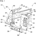
- the Figures 1 to 3 show a main frame 10 (see Figures 1 and 2 ), a cab 12 (see Figure 3 ) and a cab support device 14 (see Figures 1 and 2 ) for a motor vehicle (not shown in further detail), preferably a commercial vehicle.
- a motor vehicle preferably a commercial vehicle.
- the motor vehicle can in particular be designed as a truck. However, the techniques described herein may also be applicable to other motor vehicles.
- the main frame 10 is designed as a lead frame, but other types of main frame are also possible.
- the main frame 10 can have a first main side member 16 and a second main side member 18.
- the main side members 16 and 18 are parallel and spaced apart.
- the main side members 16 and 18 can be connected to one another by a plurality of cross members (not shown).
- the driver's cab 12 can have a front wall structure 20 (only shown in sections), a floor structure 22, a rear wall structure 24 (only shown in sections) and side wall structures 26 and / or a roof structure 28.
- the front wall structure 20 forms a front side of the driver's cab 12.
- the floor structure 22 forms a bottom or bottom side of the driver's cab 12.
- the rear wall structure 24 forms a rear of the driver's cab 12.
- the side wall structures 26 form the sides of the driver's cab 12 that extend in the longitudinal direction of the motor vehicle.
- the roof structure 28 forms an upper side of the driver's cab 12.
- the cab 12 is designed as a self-supporting cab.
- the driver's cab 12, preferably the front wall structure 20, the floor structure 22, the rear wall structure 24, the side wall structures 26 and / or the roof structure 28, is preferably formed from a lattice frame construction, as shown.
- the lattice frame construction can have a plurality of open and / or closed profiles which are firmly connected to one another at the node, i. H. are joined, for example by means of welding, gluing, screwing, deforming, etc.
- the driver's cab support structure or individual structural elements thereof can be designed alternatively or additionally as a sheet metal construction, for example with pressed sheet metal parts.
- the driver's cab 12 is designed for a commercial vehicle without an internal combustion engine on the front, which would conventionally be arranged under the driver's cab 12. Instead, the driver's cab 12 is near the ground in the assembled state with a ground clearance of, for example, less than 50 cm, in particular less than 40 cm, e.g. B. arranged around 35 cm.
- no drive device such as an internal combustion engine, is arranged below the cab 12, for example.
- the drive device of the commercial vehicle which can be an electric drive device, for example, is instead arranged at a different position of the commercial vehicle.
- the driver's cab 12 is not, as usual, arranged above a vehicle frame and sits completely on a vehicle frame, and is also not resiliently mounted on the vehicle frame. Instead, the rear of the driver's cab 12 is rigidly mounted on the (vehicle) main frame 10 via the driver's cab support device 14.
- the driver's cab 12 is preferably fastened to the driver's cab device 14 via a step 30 in the rear wall structure 24, which matches a step 32 of the driver's cab suspension device 14.
- the steps 30, 32 are matched to one another in such a way that in the assembled state they lie flat against one another, both with respect to a vertical direction and with respect to a horizontal direction (longitudinal direction of the motor vehicle).
- a peculiarity of the steps 30, 32 may be that the step surfaces of the steps 30, 32 extending in the vertical direction extend inclined to the vertical direction.
- the rigid rear connection enables the cab 12 to be positioned close to the ground, which is optimized for entry.
- the cab support device 14 is rigid, that is to say in particular non-resilient.
- the cab support device 14 supports the cab 12 on the main frame 10.
- the cab support device 14 is designed as a cab support bracket device 14.
- the cab support device 14 can preferably be constructed in several parts, for example in three parts, for example from a plurality of cab support brackets, as shown.
- the cab support device 14 has a first support component 34, a second support component 36 and a third support component 38.
- the support components 34, 36 and 38 are designed as support brackets.
- the first support component 34 can be attached directly to a driver's rear area of the rear wall structure 24.
- the first support component 34 can be fastened directly, preferably on the outside, to the first main side member 16.
- the second support component 36 can be attached directly to a rear-side region of the rear wall structure 24 on the passenger side.
- the second support component 34 can be fastened directly, preferably on the outside, to the second main longitudinal beam 18.
- the third support component 38 can be attached directly to a central rear area of the floor structure 22.
- the third support component 38 is arranged between and supported by the first support component 34 and the second support component 36.
- the third support component 38 forms a cross member construction of the cab support device 14.
- the first support component 34 and the second support component 36 can each have a horizontal contact surface 40, 42, an inclined contact surface 44, 46, and, in particular optionally, a vertical contact surface 48, 50 for flat contact with the rear of the rear wall structure 24 of the cab 12.
- the contact surfaces 40 and 44, 42 and 46, 44 and 48 and 46 and 50 adjoin each other.
- the contact surfaces 40-50 form the step 32.
- the horizontal contact surfaces 40, 42 form a horizontal step surface of the step 32.
- the contact surfaces 44, 46, 48 and 50 form an approximately vertical step surface of the step 32.
- the third support component 38 has one vertical contact surface 52 in flat contact with the back of the floor structure 22.
- the contact surfaces 44-52 are directed in one direction to a rear of the cab 12.
- the first support component 34 also has a centering element 54.
- the centering element 54 can preferably be designed as a centering mandrel, as shown.
- the centering element 54 extends in a vertical direction upwards from the horizontal Contact surface 40.
- the centering element 54 can be covered with a centering element receptacle 56 (hidden in FIG Figure 3 ) cooperate to align the cab 12 during assembly.
- the centering element receptacle 56 can be designed, for example, as a hole, for example a closely tolerated through hole.
- the driver's cab 12 can preferably be aligned in a longitudinal direction of the motor vehicle and in a transverse direction of the motor vehicle by means of the centering element 54.
- the centering element 54 and the contact surfaces 40-52 are designed and arranged in such a way that the driver's cab 12 already has two translational degrees of freedom (for example, translation along the longitudinal and transverse axes of the motor vehicle) and all three rotational degrees of freedom (rotation around the longitudinal axis, transverse axis and vertical axis of the motor vehicle) is fixed on the driver's cabin support device.
- the remaining translational degree of freedom (for example translation along the vertical axis of the motor vehicle) can then be restricted by tightening releasable fastening elements between the driver's cab 12 and the driver's cab support device 14.
- the driver's cab 12 can first be preassembled and, for example, a large part of the add-ons and fittings in and on the driver's cab 12.
- the cab support device 14 is first attached to the main frame 10.
- the main frame 10 and the cab support device 14 can be equipped with further components.
- the reason for the equipment already at this time of assembly can be the improved accessibility to the assemblies and the improved handling of the components in the assembly process.
- the preassembled cab 12 can now be lowered onto the cab support device 14 from above.
- the centering element 54 engages in the centering receptacle 56 and successively aligns the driver's cab 12 to the driver's cab support device 14 in a longitudinal direction under a transverse direction of the motor vehicle when it is lowered further.
- the rear wall structure 24 of the driver's cab 12 lies against the inclined surfaces 44, 46 and slides down there.
- the driver's cab 12 is finally completely lowered so that it lies flat against the contact surfaces 40-52.
- the driver's cab 12 is now already fixed on the driver's cab support device 14 with respect to translation along the longitudinal axis and the transverse axis of the motor vehicle by the centering element 54.
- the driver's cab is rotated about the longitudinal axis about the transverse axis and a rotation about the vertical axis on the cab support device 14.
- the releasable fastening elements can now be inserted and tightened in order to fix the driver's cab 12 to the driver's cab suspension device 14 with respect to translation along the vertical axis of the motor vehicle.
- connection points formed by the centering element 54, the contact surfaces 40-52 and the releasable fastening elements between the driver's cab 12 and the driver's cab support device 14 thus form a so-called reference point system (also called RPS), which enables reliable assembly within narrow tolerances.
- RPS reference point system
- the fastening of the support components 34, 36 and / or 38 to one another, to the driver's cab 12 and / or the main frame 10 can preferably be carried out by means of releasable fastening elements, for example by means of screws.
- the supporting components 34, 36 and 38 can each have a plurality of fastening element receptacles 58 and 60, for example through holes, for the releasable fastening elements.
- the detachable fastening elements and the fastening element receptacles 58, 60 for fastening the driver's cab suspension device 14 to the driver's cab 12 are preferably arranged in such a way that more than half, preferably more than 70%, of the releasable fastening elements are accessible from outside the driver's cab 12.
- the releasable fastening elements can thus be tightened from outside the driver's cab 12, which facilitates the mounting of the driver's cab 12, which has already been pre-assembled and equipped, on the driver's cab support device 14.
- the driver's cab 12 can thus be attached to the driver's cab support device 14 without the driver having to enter the driver's cab 12.
- the fastening element receptacles 58 arranged in the vertical direction may require tightening of the respective releasable fastening elements from inside the cab 12.
- the remaining fastening element receptacles 60 can be tightened from outside the cab 12.
- the fastening element receptacles 58 of the inclined contact surface 44 require the respective fastening elements to be tightened within the driver's cab 12.
- the fastening element receptacles 60 of the contact surfaces 40, 42, 46, 48 and / or 50 enable the respective fastening elements to be tightened outside the driver's cab 12.
- the attachment of the driver's cab 12 to the main frame 10 via the driver's cab support device 14 enables a power transmission in all main directions from the driver's cab 12 into the main frame 10. Since a large part of the Crash energy can be transmitted, the floor structure 22 can also be supported by the third support member 38.
- the inclined contact surface 44 of the first support component 34 can have a, preferably rectangular, through opening 62.
- the passage opening 62 can extend a displacement path of a driver's seat (not shown) in the cab 12 to the rear by providing a displacement space at the rear.
- a seat belt reel attached to the driver's seat can plunge into the passage opening 62 when the driver's seat is moved backwards as far as the end stop.
- the inclined contact surface 46 of the second support component 36 can have a through opening 64 for saving weight.
- the invention is not restricted to the preferred exemplary embodiments described above. Rather, a large number of variants and modifications are possible which also make use of the inventive idea and therefore fall within the scope of protection.
- the invention also claims protection for the subject and the features of the subclaims independently of the claims referred to.
- the features of independent claim 1 are disclosed independently of one another.
- the features of the subclaims are also disclosed independently of all the features of independent claim 1 and, for example, independently of the features relating to the presence and / or configuration of the main frame, the driver's cab and / or the cab support device of independent claim 1.
Landscapes
- Engineering & Computer Science (AREA)
- Chemical & Material Sciences (AREA)
- Combustion & Propulsion (AREA)
- Transportation (AREA)
- Mechanical Engineering (AREA)
- Manufacturing & Machinery (AREA)
- Body Structure For Vehicles (AREA)
Abstract
Description
- Die Erfindung betrifft ein Kraftfahrzeug mit einer Fahrerhaustragvorrichtung.
- Nutzfahrzeuge, wie Lastkraftwagen, können ein Fahrerhaus bzw. eine Fahrerkabine aufweisen. Typischerweise ist das Fahrerhaus federnd auf einem Hauptrahmen des Nutzfahrzeugs gelagert. Unterhalb des Fahrerhauses ist eine Verbrennungskraftmaschine angeordnet. Das Fahrerhaus und somit eine Sitzposition des Fahrers ist somit vergleichsweise hoch. Es ist möglich, dass das Fahrerhaus kippbar am Hauptrahmen angebracht ist, um einen Zugang zu der Verbrennungskraftmaschine zu ermöglichen.
- Herkömmliche Fahrerhauslagerungen sind bspw. aus der
EP 0 768 231 A1 und derEP 0 355 345 A2 bekannt. - Der Erfindung liegt die Aufgabe zu Grunde, eine alternative und/oder verbesserte Tragkonstruktion für ein Kraftfahrzeug zu schaffen.
- Die Aufgabe wird gelöst durch die Merkmale des unabhängigen Anspruchs 1. Vorteilhafte Weiterbildungen sind in den abhängigen Ansprüchen und der Beschreibung angegeben.
- Die Erfindung betrifft ein Kraftfahrzeug, vorzugsweise ein Nutzfahrzeug, vorzugsweise Lastkraftwagen oder Omnibus. Das Kraftfahrzeug weist ein Fahrerhaus (z. B. Lastkraftwagen-Fahrerhauskabine) und einen Hauptrahmen (z. B. Leiterrahmen) auf. Das Kraftfahrzeug weist eine starre Fahrerhaustragvorrichtung auf. Die starre Fahrerhaustragvorrichtung trägt das Fahrerhaus starr an einer Rückseite des Fahrerhauses (z. B. eine Rückseite einer Rückwandstruktur des Fahrerhauses und/oder eine Rückseite einer Bodenstruktur des Fahrerhauses). Die starre Fahrerhaustragvorrichtung ist starr von dem Hauptrahmen getragen.
- Die rückseitige, starre Fahrerhaustragvorrichtung sowie der Verzicht auf eine federnde Lagerung des Fahrerhauses am Hauptrahmen ermöglichen eine niedrige, bodennahe Anordnung des Fahrerhauses. Dies kann insbesondere vorteilhaft bei Nutzfahrzeugen, die einer hohen Ein- und Ausstiegshäufigkeit unterliegen, sein, um die körperliche Belastung beim Ein- und Aussteigen für die Fahrzeugbesatzung zu minimieren. Darüber hinaus gewährleistet eine niedrige Anordnung des Fahrerhauses und eine damit einhergehende niedrige Sitzposition des Fahrzeugführers eine optimierte direkte Sicht auf die Fahrzeugumgebung und auf andere Verkehrsteilnehmer.
- Zweckmäßig kann das Kraftfahrzeug auch ohne frontseitige und/oder unter dem Fahrerhaus angeordnete Antriebseinrichtung, insbesondere Verbrennungskraftmaschine, ausgebildet sein.
- Es ist möglich, dass das Fahrerhaus selbsttragend ist, zum Beispiel durch eine Gitterrahmenkonstruktion und/oder eine Blechkonstruktion.
- Beispielsweise kann der Hauptrahmen bezüglich einer Vorwärtsfahrtrichtung des Kraftfahrzeugs hinter dem Fahrerhaus (z. B. vollständig) angeordnet sein.
- Es ist möglich, dass die Rückseite des Fahrerhauses entgegengesetzt zu einer Vorwärtsfahrtrichtung des Kraftfahrzeugs gerichtet ist.
- In einem Ausführungsbeispiel weist die starre Fahrerhaustragvorrichtung mindestens eine Anlagefläche auf, die zu einer Horizontalachse und zu einer Vertikalachse geneigt ist und flächig an der Rückseite des Fahrerhauses anliegt. Die geneigte Anlagefläche kann eine Montage und Positionierung des Fahrerhauses an der Fahrerhaustragvorrichtung erleichtern.
- In einem weiteren Ausführungsbeispiel ist die Rückseite des Fahrerhauses (z. B. eine Rückseite einer Rückwandstruktur des Fahrerhauses) mit einer Stufe ausgebildet, die bezüglich einer Vertikalrichtung und bezüglich einer Horizontalrichtung, vorzugsweise flächig, an der starren Fahrerhaustragvorrichtung anliegt. Alternativ oder zusätzlich kann die starre Fahrerhaustragvorrichtung mit einer Stufe ausgebildet sein, die bezüglich einer Vertikalrichtung und bezüglich einer Horizontalrichtung, vorzugsweise flächig, an der Rückseite des Fahrerhauses anliegt. Die Stufen können zweckmäßig einander angepasst sein. Die Stufen können eine Positionierung des Fahrerhauses zur Fahrerhaustragvorrichtung bei der Montage erleichtern.
- In einer Weiterbildung kann eine sich in Vertikalrichtung erstreckende Stufenfläche der Stufe des Fahrerhauses und/oder der Fahrerhaustragvorrichtung geneigt zu einer Vertikalachse sein.
- In einem weiteren Ausführungsbeispiel weist eines von der starren Fahrerhaustragvorrichtung und dem Fahrerhaus ein Zentrierelement und das andere von der starren Fahrerhaustragvorrichtung und dem Fahrerhaus eine Zentrierelementaufnahme für das Zentrierelement auf. Beispielsweise kann das Zentrierelement eine Ausrichtung des Fahrerhauses zur Fahrerhaustragvorrichtung in unterschiedlichen Richtungen während der Montage ermöglichen.
- In einer Weiterbildung ist das Zentrierelement konisch und/oder als ein Zentrierdorn ausgebildet. Alternativ oder zusätzlich ist die Zentrierelementaufnahme als ein Loch, vorzugsweise ein Durchgangsloch ausgebildet. Das Zentrierelement kann somit eine allmähliche Ausrichtung zum Beispiel während eines Absetzens des Fahrerhauses auf der Fahrerhaustragvorrichtung ermöglichen.
- In einer Weiterbildung ist das Zentrierelement in einer Vertikalrichtung ausgerichtet und/oder das Zentrierelement und die Zentrierelementaufnahme richten das Fahrerhaus und die starre Fahrerhaustragvorrichtung in einer Längsrichtung des Kraftfahrzeugs und/oder in einer Querrichtung des Kraftfahrzeugs zueinander ausrichten.
- In einer Ausführungsform sind die starre Fahrerhaustragvorrichtung und das Fahrerhaus (z. B. die Rückseite des Fahrerhauses) so ausgebildet, dass das Fahrerhaus und die starre Fahrerhaustragvorrichtung bereits durch eine Zentrierung (z. B. durch das Zentrierelement) und mehrere flächige Kontakte zwischen der starren Fahrerhaustragvorrichtung und dem Fahrerhaus bezüglich zweier translatorischer Freiheitsgrade (zum Beispiel Translation entlang einer Querachse und einer Längsachse des Kraftfahrzeugs) und bezüglich aller drei rotatorischen Freiheitsgrade zueinander festgelegt sind. Das Fahrerhaus kann somit mit einer hohen Genauigkeit bezüglich der Fahrerhaustragvorrichtung positioniert und montiert werden. Die so gewählten Anbindungspunkte zwischen dem Fahrerhaus und der Fahrerhaustragvorrichtung ermöglichen die Realisierung eines sogenannten Referenzpunktsystems zur Gewährleistung besonders geringer Toleranzen bei der Montage.
- Zweckmäßig kann das Fahrerhaus an der Fahrerhaustragvorrichtung bezüglich des dritten translatorischen Freiheitsgrads (zum Beispiel Translation entlang einer Hochachse des Kraftfahrzeugs) mittel lösbarer Befestigungselemente festgelegt sein.
- In einer weiteren Ausführungsform ist die starre Fahrerhaustragvorrichtung als eine Tragkonsolenvorrichtung ausgebildet.
- In einer weiteren Ausführungsform ist die starre Fahrerhaustragvorrichtung mehrteilig, vorzugsweise dreiteilig.
- In einer Ausführungsvariante ist die starre Fahrerhaustragvorrichtung über mehrere lösbare Befestigungselemente an dem Fahrerhaus befestigt, die so angeordnet sind, dass mehr als die Hälfte, vorzugsweise mehr als 70 % der lösbaren Befestigungselemente von außerhalb des Fahrerhauses zugängig sind (z. B. zum Lösen und Anziehen). Das Fahrerhaus kann somit bereits sicher an der Fahrerhaustragvorrichtung befestigt werden, ohne dass das Fahrerhaus betreten werden muss.
- In einer weiteren Ausführungsvariante begrenzt das Fahrerhaus das Kraftfahrzeug nach unten hin. Das Fahrerhaus kann beispielsweise einen Bodenabstand von weniger als 50 cm, vorzugsweise weniger als 40 cm, aufweisen.
- In einer weiteren Ausführungsvariante ist ein (erstes) Tragbauteil der starren Fahrerhaustragvorrichtung (z. B. direkt) an einem fahrerseitigen Rückseitenbereich der Rückseite des Fahrerhauses befestigt.
- In einer weiteren Ausführungsform ist ein (zweites) Tragbauteil der starren Fahrerhaustragvorrichtung (z. B. direkt) an einem beifahrerseitigen Rückseitenbereich der Rückseite des Fahrerhauses befestigt.
- In einer weiteren Ausführungsform ist ein (drittes) Tragbauteil der starren Fahrerhaustragvorrichtung (z. B. direkt) an einer Rückseite einer Bodenstruktur des Fahrerhauses befestigt.
- In einer weiteren Ausführungsform ist das erste Tragbauteil (z. B. direkt) an einem ersten Längsträger des Hauptrahmens befestigt, das zweite Tragbauteil (z. B. direkt) an einem zweiten Längsträger des Hauptrahmens befestigt und/oder das dritte Tragbauteil zwischen dem ersten Tragbauteil und dem zweiten Tragbauteil angeordnet.
- In einem Ausführungsbeispiel ist das dritte Tragbauteil als eine Querträgerkonstruktion ausgeführt und/oder das dritte Tragbauteil ist von dem ersten Tragbauteil und dem zweiten Tragbauteil getragen.
- In einem weiteren Ausführungsbeispiel ist das erste Tragbauteil, das zweite Tragbauteil und/oder das dritte Tragbauteil als eine Tragkonsole ausgebildet.
- In einer Ausführungsvariante weist das erste Tragbauteil eine horizontale Anlagefläche in flächiger Anlage mit dem Fahrerhaus (z. B. einer Stufenfläche des Fahrerhauses), eine zu einer Horizontalachse und zu einer Vertikalachse geneigte Anlagefläche in flächiger Anlage mit dem Fahrerhaus (z. B. der Rückseite des Fahrerhauses) und/oder eine vertikale Anlagefläche in flächiger Anlage mit dem Fahrerhaus (z. B. der Rückseite des Fahrerhauses) auf.
- In einer weiteren Ausführungsvariante weist das zweite Tragbauteil eine horizontale Anlagefläche in flächiger Anlage mit dem Fahrerhaus(z. B. einer Stufenfläche des Fahrerhauses), eine zu einer Horizontalachse und zu einer Vertikalachse geneigte Anlagefläche in flächiger Anlage mit dem Fahrerhaus (z. B. der Rückseite des Fahrerhauses) und/oder eine vertikale Anlagefläche in flächiger Anlage mit dem Fahrerhaus (z. B. der Rückseite des Fahrerhauses) auf.
- Zweckmäßig kann die Stufe der Fahrerhaustragvorrichtung zumindest teilweise durch die horizontale Anlagefläche und die geneigte Anlagefläche des ersten Tragbauteil und/oder des zweiten Tragbauteil gebildet sein.
- In einer weiteren Ausführungsvariante weist das dritte Tragbauteil eine vertikale Anlagefläche in flächiger Anlage mit dem Fahrerhaus (z. B. der Rückseite des Fahrerhauses, z. B. einer Rückseite einer Bodenstruktur des Fahrerhauses) auf.
- Es ist möglich, dass die horizontale Anlagefläche des ersten Tragbauteils und/oder des zweiten Tragbauteils mehrere Befestigungselementaufnahmen (zum Beispiel Durchgangslöcher) für lösbare Befestigungselemente (zum Beispiel Schrauben) zum Befestigen an dem Fahrerhaus aufweisen, wobei vorzugsweise die mehreren Befestigungselementaufnahmen so angeordnet sind, dass die jeweiligen Befestigungselemente von außerhalb des Fahrerhauses zugängig sind (z. B. zum Lösen und Anziehen).
- Es ist auch möglich, dass die vertikale Anlagefläche des ersten Tragbauteils, des zweiten Tragbauteils und/oder des dritten Tragbauteils, und/oder die geneigte Anlagefläche des zweiten Tragbauteils mehrere Befestigungselementaufnahmen (zum Beispiel Durchgangslöcher) für lösbare Befestigungselemente (zum Beispiel Schrauben) zum Befestigen an dem Fahrerhaus aufweisen, wobei vorzugsweise die mehreren Befestigungselementaufnahmen so angeordnet sind, dass die jeweiligen Befestigungselemente von außerhalb des Fahrerhauses zugängig sind (z. B. zum Lösen und Anziehen).
- Es ist ferner möglich, dass (zum Beispiel nur) die geneigte Anlagefläche des ersten Tragbauteils mehrere Befestigungselementaufnahmen (zum Beispiel Durchgangslöcher) für lösbare Befestigungselemente (zum Beispiel Schrauben) zum Befestigen an dem Fahrerhaus aufweisen, wobei vorzugsweise die mehreren Befestigungselementaufnahmen so angeordnet sind, dass die jeweiligen Befestigungselemente nur innerhalb des Fahrerhauses zugängig sind (z. B. zum Lösen und Anziehen).
- In einem Ausführungsbeispiel weist das erste Tragbauteil oder das zweite Tragbauteil ein, vorzugsweise konisches, Zentrierelement, vorzugsweise einen Zentrierdorn, zum Ausrichten des Fahrerhauses auf. Vorzugsweise erstreckt sich das Zentrierelement ausgehend von der horizontalen Anlagefläche des ersten Tragbauteils oder des zweiten Tragbauteils in einer Vertikalrichtung nach oben.
- In einem weiteren Ausführungsbeispiel weist die zur Horizontalachse und zur Vertikalachse geneigte Anlagefläche des ersten Tragbauteils eine, vorzugsweise rechteckförmige, Durchgangsöffnung zum Bereitstellen eines rückseitigen Verschieberaums für einen (z. B. längs-) verschiebbaren Fahrersitz des Fahrerhauses auf. Zweckmäßig kann so der Fahrersitz oder eine daran montierte Komponente zumindest teilweise in die Durchgangsöffnung eintauchen, z. B. wenn der Fahrersitz ganz nach hinten verstellt wird, sodass der mögliche Verschiebeweg des Fahrersitzes verlängert wird.
- In einem weiteren Ausführungsbeispiel weist die zur Horizontalachse und zur Vertikalachse geneigte Anlagefläche des zweiten Tragbauteils eine Durchgangsöffnung zur Gewichtseinsparung auf.
- Die Erfindung betrifft auch ein Verfahren zur Montage eines Kraftfahrzeugs wie hierin offenbart. Das Verfahren weist das Vormontieren des Fahrerhauses und das Montieren der starren Fahrerhaustragvorrichtung am Hauptrahmen auf. Das Verfahren weist ferner das Absenken des vormontierten Fahrerhauses auf die am Hauptrahmen montierte, starre Fahrerhaustragvorrichtung auf.
- In einer Weiterbildung erfolgt beim Absenken eine sukzessive Ausrichtung des Fahrerhauses zur Fahrerhaustragvorrichtung in einer Längsrichtung des Kraftfahrzeugs und in einer Querrichtung des Kraftfahrzeugs mittels des Zentrierelements, während das Fahrerhaus an der zur Horizontalachse und zur Vertikalachse geneigten Anlagefläche des ersten Tragbauteils und/oder an der zur Horizontalachse und zur Vertikalachse geneigten Anlagefläche des zweiten Tragbauteils entlanggleitet (z.B. nach unten). Das Fahrerhaus und die Fahrerhaustragvorrichtung können so auf besonders vorteilhafte Weise genau zueinander ausgerichtet und positioniert werden, um anschließend mittels lösbarer Befestigungselemente aneinander fixiert zu werden.
- Die zuvor beschriebenen bevorzugten Ausführungsformen und Merkmale der Erfindung sind beliebig miteinander kombinierbar. Weitere Einzelheiten und Vorteile der Erfindung werden im Folgenden unter Bezug auf die beigefügten Zeichnungen beschrieben. Es zeigen:
- Figur 1
- eine perspektivische Ansicht einer Fahrerhaustragvorrichtung und eines Abschnitts eines Hauptrahmens gemäß der vorliegenden Offenbarung;
- Figur 2
- eine Seitenansicht der Fahrerhaustragvorrichtung und eines Abschnitts des Hauptrahmens; und
- Figur 3
- eine perspektivische Ansicht eines Ausschnitts eines Fahrerhauses gemäß der vorliegenden Offenbarung.
- Die in den Figuren gezeigten Ausführungsformen stimmen zumindest teilweise überein, so dass ähnliche oder identische Teile mit den gleichen Bezugszeichen versehen sind und zu deren Erläuterung auch auf die Beschreibung der anderen Ausführungsformen bzw. Figuren verwiesen wird, um Wiederholungen zu vermeiden.
- Die
Figuren 1 bis 3 zeigen einen Hauptrahmen 10 (sieheFiguren 1 und2 ), ein Fahrerhaus 12 (sieheFigur 3 ) und eine Fahrerhaustragvorrichtung 14 (sieheFiguren 1 und2 ) für ein Kraftfahrzeug (nicht in weiterem Detail dargestellt), vorzugsweise ein Nutzfahrzeug. Das Kraftfahrzeug kann insbesondere als ein Lastkraftwagen ausgebildet sein. Die hierin beschrieben Techniken können allerdings auch für andere Kraftfahrzeuge anwendbar sein. - In der dargestellten Ausführungsform ist der Hauptrahmen 10 als ein Leiterrahmen ausgebildet, allerdings sind auch andere Typen von Hauptrahmen möglich. Der Hauptrahmen 10 kann einen ersten Hauptlängsträger 16 und einen zweiten Hauptlängsträger 18 aufweisen. Die Hauptlängsträger 16 und 18 verlaufen parallel beabstandet zueinander. Die Hauptlängsträger 16 und 18 können durch mehrere Querträger (nicht dargestellt) miteinander verbunden sein.
- Das Fahrerhaus 12 kann eine Vorderwandstruktur 20 (nur abschnittsweise dargestellt), eine Bodenstruktur 22, eine Rückwandstruktur 24 (nur abschnittsweise dargestellt) sowie Seitenwandstrukturen 26 und/oder eine Dachstruktur 28 aufweisen. Die Vorderwandstruktur 20 bildet eine Vorderseite des Fahrerhauses 12. Die Bodenstruktur 22 bildet eine Unterseite oder Bodenseite des Fahrerhauses 12. Die Rückwandstruktur 24 bildet eine Rückseite des Fahrerhauses 12. Die Seitenwandstrukturen 26 bilden die sich in Längsrichtung des Kraftfahrzeugs erstreckenden Seiten des Fahrerhauses 12. Die Dachstruktur 28 bildet eine Oberseite des Fahrerhauses 12.
- Das Fahrerhaus 12 ist als selbsttragendes Fahrerhaus konzipiert. Vorzugsweise ist das Fahrerhaus 12, vorzugsweise die Vorderwandstruktur 20, die Bodenstruktur 22, die Rückwandstruktur 24, die Seitenwandstrukturen 26 und/oder die Dachstruktur 28, aus einer Gitterrahmenkonstruktion gebildet, wie dargestellt ist. Die Gitterrahmenkonstruktion kann eine Mehrzahl von offenen und/oder geschlossenen Profilen aufweisen, die in Knotenpunkt fest miteinander verbunden, d. h. gefügt, sind, zum Beispiel mittels Verschweißen, Verkleben, Verschrauben, Verformen usw.. Es ist auch möglich, dass die Fahrerhaustragstruktur oder einzelne Strukturelemente davon alternativ oder zusätzlich als eine Blechkonstruktion ausgebildet ist, zum Beispiel mit Blechpressteilen.
- In der gezeigten, beispielhaften Ausführungsform ist das Fahrerhaus 12 für ein Nutzfahrzeug ohne frontseitige Verbrennungskraftmaschine ausgebildet, die herkömmlich unter dem Fahrerhaus 12 angeordnet wäre. Stattdessen ist das Fahrerhaus 12 im montierten Zustand bodennah mit einem Bodenabstand von beispielsweise weniger als 50 cm, insbesondere weniger als 40 cm, z. B. rund 35 cm angeordnet. Das Fahrerhaus 12, vorzugsweise die Bodenstruktur 22, grenzt das Nutzfahrzeug zum Boden hin ab. Mit anderen Worten gesagt, unterhalb des Fahrerhauses 12 und insbesondere der Bodenstruktur 22 sind keine tragenden Teile eines Fahrzeugrahmens angeordnet. Ferner ist unterhalb des Fahrerhauses 12 beispielsweise keine Antriebseinrichtung, wie eine Verbrennungskraftmaschine, angeordnet. Die Antriebseinrichtung des Nutzfahrzeugs, die beispielsweise eine Elektro-Antriebseinrichtung sein kann, ist stattdessen an einer anderen Position des Nutzfahrzeugs angeordnet.
- Damit sitzt das Fahrerhaus 12 nicht, wie üblich, oberhalb eines Fahrzeugrahmens angeordnet und sitzt vollständig auf einem Fahrzeugrahmen auf, und ist auch nicht federnd auf dem Fahrzeugrahmen gelagert. Stattdessen ist das Fahrerhaus 12 rückseitig starr über die Fahrerhaustragvorrichtung 14 an dem (Fahrzeug-) Hauptrahmen 10 gelagert.
- Vorzugsweise ist das Fahrerhaus 12 über eine Stufe 30 in der Rückwandstruktur 24, die mit einer Stufe 32 der Fahrerhaustragvorrichtung 14 zusammenpasst, an der Fahrerhaustragvorrichtung 14 befestigt. Die Stufen 30, 32 sind so aneinander angepasst, dass sie im montierten Zustand flächig aneinander anliegen, sowohl bezüglich einer Vertikalrichtung als auch bezüglich einer Horizontalrichtung (Längsrichtung des Kraftfahrzeugs). Wie hierin im Detail erklärt ist, kann eine Besonderheit der Stufen 30, 32 darin bestehen, dass sich die in Vertikalrichtung erstreckende Stufenflächen der Stufen 30, 32 geneigt zur Vertikalrichtung erstreckt. Die rückseitige, starre Anbindung ermöglicht die hinsichtlich eines Einstiegs optimierte, bodennahe Anordnung des Fahrerhauses 12.
- Die Fahrerhaustragvorrichtung 14 ist starr, das heißt insbesondere nicht-federnd, ausgebildet. Die Fahrerhaustragvorrichtung 14 trägt das Fahrerhaus 12 am Hauptrahmen 10. Die Fahrerhaustragvorrichtung 14 ist als eine Fahrerhaustragkonsolenvorrichtung 14 ausgebildet. Vorzugsweise kann die Fahrerhaustragvorrichtung 14 mehrteilig, zum Beispiel dreiteilig, ausgebildet sein, zum Beispiel aus mehreren Fahrerhaustragkonsolen, wie dargestellt ist.
- Im gezeigten Ausführungsbeispiel weist die Fahrerhaustragvorrichtung 14 ein erstes Tragbauteil 34, ein zweites Tragbauteil 36 und ein drittes Tragbauteil 38 auf. Die Tragbauteile 34, 36 und 38 sind als Tragkonsolen ausgebildet.
- Das erste Tragbauteil 34 kann direkt an einem fahrerseitigen Rückseitenbereich der Rückwandstruktur 24 befestigt werden. Das erste Tragbauteil 34 kann direkt, vorzugsweise außenseitig, an dem ersten Hauptlängsträger 16 befestigt sein.
- Das zweite Tragbauteil 36 kann direkt an einem beifahrerseitigen Rückseitenbereich der Rückwandstruktur 24 befestigt werden. Das zweite Tragbauteil 34 kann direkt, vorzugsweise außenseitig, an dem zweiten Hauptlängsträger 18 befestigt sein.
- Das dritte Tragbauteil 38 kann direkt an einem mittleren Rückseitenbereich der Bodenstruktur 22 befestigt werden. Das dritte Tragbauteil 38 ist zwischen dem ersten Tragbauteil 34 und dem zweiten Tragbauteil 36 angeordnet und von diesen getragen. Das dritte Tragbauteil 38 bildet eine Querträgerkonstruktion der Fahrerhaustragvorrichtung 14.
- Das erste Tragbauteil 34 und das zweite Tragbauteil 36 können jeweils eine horizontale Anlagefläche 40, 42, eine geneigte Anlagefläche 44, 46, und, insbesondere optional, eine vertikale Anlagefläche 48, 50 zur flächigen Anlage an die Rückseite der Rückwandstruktur 24 des Fahrerhaus 12 aufweisen. Es grenzen jeweils die Anlageflächen 40 und 44, 42 und 46, 44 und 48 sowie 46 und 50 aneinander. Die Anlageflächen 40-50 bilden die Stufe 32. Im Einzelnen bilden die horizontalen Anlageflächen 40, 42 eine horizontale Stufenfläche der Stufe 32. Die Anlageflächen 44, 46, 48 und 50 bilden eine annähernd vertikale Stufenfläche der Stufe 32. Das dritte Tragbauteil 38 weist eine vertikale Anlagefläche 52 in flächiger Anlage mit der Rückseite der Bodenstruktur 22 auf. Die Anlageflächen 44-52 sind in einer Richtung zu einer Rückseite des Fahrerhauses 12 gerichtet.
- Das erste Tragbauteil 34 weist ferner ein Zentrierelement 54 auf. Vorzugsweise kann das Zentrierelement 54 als ein Zentrierdorn ausgeführt sein, wie dargestellt ist. Das Zentrierelement 54 erstreckt sich in einer Vertikalrichtung nach oben ausgehend von der horizontalen Anlagefläche 40. Das Zentrierelement 54 kann mit einer Zentrierelementaufnahme 56 (verdeckt in
Figur 3 ) zusammenwirken, um das Fahrerhaus 12 bei der Montage auszurichten. Die Zentrierelementaufnahme 56 kann beispielsweise als ein Loch, zum Beispiel ein eng toleriertes Durchgangsloch, ausgebildet sein. Vorzugsweise kann das Fahrerhaus 12 bei der Montage durch das Zentrierelement 54 in einer Längsrichtung des Kraftfahrzeugs und in einer Querrichtung des Kraftfahrzeugs ausgerichtet werden. - Das Zentrierelement 54 und die Anlageflächen 40-52 sind so ausgebildet und angeordnet, dass das Fahrerhaus 12 bei der Montage durch diese bereits bezüglich zweier translatorischer Freiheitsgrade (zum Beispiel Translation entlang der Längsachse und Querachse des Kraftfahrzeugs) und bezüglich aller drei rotatorischen Freiheitsgrade (Rotation um die Längsachse, Querachse und Hochachse des Kraftfahrzeugs) an der Fahrerhaustragvorrichtung festgelegt ist. Der übrige translatorisch Freiheitsgrad (zum Beispiel Translation entlang der Hochachse des Kraftfahrzeugs) kann dann durch Anziehen von lösbaren Befestigungselementen zwischen dem Fahrerhaus 12 und der Fahrerhaustragvorrichtung 14 beschränkt sein.
- Beispielsweise kann in einem Verfahren zur Montage des Kraftfahrzeugs zunächst das Fahrerhaus 12 vormontiert und dabei bspw. ein Großteil der An- und Einbauten im und am Fahrerhaus 12 angebaut werden. Die Fahrerhaustragvorrichtung 14 wird zunächst am Hauptrahmen 10 befestigt. Der Hauptrahmen 10 und die Fahrerhaustragvorrichtung 14 können mit weiteren Komponenten ausgestattet werden. Der Grund für die Ausstattung bereits zu diesem Montagezeitpunkt kann in der verbesserten Zugänglichkeit zu den Baugruppen und dem verbesserten Handling der Komponenten im Montageprozess liegen.
- Das vormontierte Fahrerhaus 12 kann nun von oben auf die Fahrerhaustragvorrichtung 14 abgesenkt werden. Hierbei greift das Zentrierelement 54 in die Zentrieraufnahme 56 ein und richtet das Fahrerhaus 12 zur Fahrerhaustragvorrichtung 14 in einer Längsrichtung unter einer Querrichtung des Kraftfahrzeugs beim weiteren Absenken sukzessive aus. Gleichzeitig legt sich die Rückwandstruktur 24 des Fahrerhauses 12 an die geneigten Flächen 44, 46 an und gleitet an diesen hinab. Das Fahrerhaus 12 wird schließlich vollständig abgesetzt, sodass es flächig an den Anlageflächen 40-52 anliegt. Das Fahrerhaus 12 ist nun bereits bezüglich einer Translation entlang der Längsachse und der Querachse des Kraftfahrzeugs durch das Zentrierelement 54 an der Fahrerhaustragvorrichtung 14 festgelegt. Zusätzlich ist das Fahrerhaus 12 durch Zusammenwirken der flächigen Anlagen der Anlageflächen 40-52 und der Zentrierung durch das Zentrierelement 54 bezüglich einer Rotation um die Längsachse, einer Rotation um die Querachse und einer Rotation um die Hochachse an der Fahrerhaustragvorrichtung 14 festgelegt. Nun können die lösbare Befestigungselemente eingesetzt und angezogen werden, um das Fahrerhaus 12 bezüglich einer Translation entlang der Hochachse des Kraftfahrzeugs an der Fahrerhaustragvorrichtung 14 festzulegen. Die durch das Zentrierelement 54, die Anlageflächen 40-52 und die lösbaren Befestigungselemente gebildeten Anbindungspunkte zwischen dem Fahrerhaus 12 und der Fahrerhaustragvorrichtung 14 bilden somit ein sogenanntes Referenzpunkt System (auch RPS genannt), was eine zuverlässige Montage innerhalb enger Toleranzen ermöglicht.
- Die Befestigung der Tragbauteile 34, 36 und/oder 38 aneinander, an dem Fahrerhaus 12 und/oder dem Hauptrahmen 10 kann vorzugsweise mittels lösbare Befestigungselemente, zum Beispiel mittels Schrauben, ausgeführt sein. Die Tragbauteile 34, 36 und 38 können jeweils mehrere Befestigungselementaufnahmen 58 und 60, zum Beispiel Durchgangslöcher, für die lösbare Befestigungselemente aufweisen. Vorzugsweise sind die lösbare Befestigungselemente und die Befestigungselementaufnahmen 58, 60 zur Befestigung der Fahrerhaustragvorrichtung 14 an dem Fahrerhaus 12 so angeordnet, dass mehr als die Hälfte, vorzugsweise mehr als 70 % der lösbaren Befestigungselemente von außerhalb des Fahrerhauses 12 zugängig sind. Die lösbaren Befestigungselemente können so von außerhalb des Fahrerhauses 12 angezogen werden, was die Montage des insbesondere bereits vormontierten und ausgestatteten Fahrerhauses 12 an der Fahrerhaustragvorrichtung 14 erleichtert. Das Fahrerhaus 12 kann somit an der Fahrerhaustragvorrichtung 14 befestigt werden, ohne dass das Fahrerhaus 12 von einem Monteur betreten werden muss.
- Beispielsweise kann lediglich die in Vertikalrichtung angeordnete Reihe der Befestigungselementaufnahmen 58 ein Anziehen der jeweiligen lösbaren Befestigungselemente von innerhalb des Fahrerhauses 12 erfordern. Die übrigen Befestigungselementaufnahmen 60 können von außerhalb des Fahrerhauses 12 angezogen werden. In anderen Worten, die Befestigungselementaufnahmen 58 der geneigten Anlagefläche 44 erfordern ein Festziehen der jeweiligen Befestigungselemente innerhalb des Fahrerhauses 12. Die Befestigungselementaufnahmen 60 der Anlageflächen 40, 42, 46, 48 und/oder 50 ermöglichen ein Festziehen der jeweiligen Befestigungselemente außerhalb des Fahrerhauses 12.
- Die Befestigung des Fahrerhauses 12 über die Fahrerhaustragvorrichtung 14 an dem Hauptrahmen 10 ermöglicht eine Kraftübertragung in allen Hauptrichtungen von dem Fahrerhaus 12 in den Hauptrahmen 10. Da über die Bodenstruktur 22 bei einem Frontalcrash ein Großteil der Crashenergie übertragen werden kann, kann die Bodenstruktur 22 zusätzlich durch das dritte Tragbauteil 38 abgestützt sein.
- Wie ferner in
Figur 1 dargestellt ist, kann die geneigte Anlagefläche 44 des ersten Tragbauteils 34 eine, vorzugsweise rechteckförmige, Durchgangsöffnung 62 aufweisen. Die Durchgangsöffnung 62 kann einen Verschiebeweg eines Fahrersitzes (nicht dargestellt) im Fahrerhaus 12 nach hinten durch Bereitstellen eines rückseitigen Verschieberaums verlängern. Beispielsweise kann eine am Fahrersitz befestigte Gurtrolle in die Durchgangsöffnung 62 eintauchen, wenn der Fahrersitz bis zum Endanschlag nach hinten verschoben wird. Es ist auch möglich, dass die geneigte Anlagefläche 46 des zweiten Tragbauteils 36 eine Durchgangsöffnung 64 zur Gewichtseinsparung aufweist. - Die Erfindung ist nicht auf die vorstehend beschriebenen bevorzugten Ausführungsbeispiele beschränkt. Vielmehr ist eine Vielzahl von Varianten und Abwandlungen möglich, die ebenfalls von dem Erfindungsgedanken Gebrauch machen und deshalb in den Schutzbereich fallen. Insbesondere beansprucht die Erfindung auch Schutz für den Gegenstand und die Merkmale der Unteransprüche unabhängig von den in Bezug genommenen Ansprüchen. Insbesondere sind die Merkmale des unabhängigen Anspruchs 1 unabhängig voneinander offenbart. Zusätzlich sind auch die Merkmale der Unteransprüche unabhängig von sämtlichen Merkmalen des unabhängigen Anspruchs 1 und beispielsweise unabhängig von den Merkmalen bezüglich des Vorhandenseins und/oder der Konfiguration des Hauptrahmens, der Fahrerkabine und/oder der Fahrerhaustragvorrichtung des unabhängigen Anspruchs 1 offenbart.
-
- 10
- Hauptrahmen
- 12
- Fahrerhaus
- 14
- Fahrerhaustragvorrichtung
- 16
- Erster Hauptlängsträger
- 18
- Zweiter Hauptlängsträger
- 20
- Vorderwandstruktur
- 22
- Bodenstruktur
- 24
- Rückwandstruktur
- 26
- Seitenwandstruktur
- 28
- Dachstruktur
- 30
- Stufe
- 32
- Stufe
- 34
- (Erstes) Tragbauteil
- 36
- (Zweites) Tragbauteil
- 38
- (Drittes) Tragbauteil
- 40-52
- Anlageflächen
- 54
- Zentrierelement
- 56
- Zentrierelementaufnahme
- 58, 60
- Befestigungselementaufnahmen
- 62
- Durchgangsöffnung
- 64
- Durchgangsöffnung
Claims (15)
- Kraftfahrzeug, vorzugsweise Nutzfahrzeug, vorzugsweise Lastkraftwagen, aufweisend:ein Fahrerhaus (12);einen Hauptrahmen (10); undeine starre Fahrerhaustragvorrichtung (14), die das Fahrerhaus (12) starr an einer Rückseite des Fahrerhauses (12) trägt und starr von dem Hauptrahmen (10) getragen ist.
- Kraftfahrzeug nach Anspruch 1, wobei:
die starre Fahrerhaustragvorrichtung (14) mindestens eine Anlagefläche (44, 46) aufweist, die zu einer Horizontalachse und zu einer Vertikalachse geneigt ist und flächig an der Rückseite des Fahrerhauses (12) anliegt. - Kraftfahrzeug nach Anspruch 1 oder Anspruch 2, wobei:die Rückseite des Fahrerhauses (12) mit einer Stufe (30) ausgebildet ist, die bezüglich einer Vertikalrichtung und bezüglich einer Horizontalrichtung, vorzugsweise flächig, an der starren Fahrerhaustragvorrichtung (14) anliegt; und/oderdie starre Fahrerhaustragvorrichtung (14) mit einer Stufe (32) ausgebildet ist, die bezüglich einer Vertikalrichtung und bezüglich einer Horizontalrichtung, vorzugsweise flächig, an der Rückseite des Fahrerhauses (12) anliegt.
- Kraftfahrzeug nach Anspruch 3, wobei:
eine sich in Vertikalrichtung erstreckende Stufenfläche der Stufe (30, 32) des Fahrerhauses (12) und/oder der Fahrerhaustragvorrichtung (14) geneigt zu einer Vertikalachse ist. - Kraftfahrzeug nach einem der vorherigen Ansprüche, wobei:
eines von der starren Fahrerhaustragvorrichtung (14) und dem Fahrerhaus (12) ein Zentrierelement (54) und das andere von der starren Fahrerhaustragvorrichtung (14) und dem Fahrerhaus (12) eine Zentrierelementaufnahme (56) für das Zentrierelement (54) aufweist. - Kraftfahrzeug nach Anspruch 5, wobei:das Zentrierelement (54) konisch und oder als ein Zentrierdorn ausgebildet ist; und/oderdie Zentrierelementaufnahme (56) als ein Loch, vorzugsweise ein Durchgangsloch ausgebildet ist; und/oderdas Zentrierelement (54) in einer Vertikalrichtung ausgerichtet ist; und/oder das Zentrierelement (54) und die Zentrierelementaufnahme (56) das Fahrerhaus (12) und die starre Fahrerhaustragvorrichtung (14) in einer Längsrichtung des Kraftfahrzeugs und in einer Querrichtung des Kraftfahrzeugs zueinander ausrichten.
- Kraftfahrzeug nach einem der vorherigen Ansprüche, wobei:
die starre Fahrerhaustragvorrichtung (14) und das Fahrerhaus (12) so ausgebildet sind, dass das Fahrerhaus (12) und die starre Fahrerhaustragvorrichtung (14) bereits durch eine Zentrierung und mehrere flächige Kontakte zwischen der starren Fahrerhaustragvorrichtung (14) und dem Fahrerhaus (12) bezüglich zweier translatorischer Freiheitsgrade und bezüglich aller drei rotatorischen Freiheitsgrade zueinander festgelegt sind. - Kraftfahrzeug nach einem der vorherigen Ansprüche, wobei:die starre Fahrerhaustragvorrichtung (14) als eine Tragkonsolenvorrichtung ausgebildet ist; und/oderdie starre Fahrerhaustragvorrichtung (14) mehrteilig, vorzugsweise dreiteilig, ist; und/oderdie starre Fahrerhaustragvorrichtung (14) über mehrere lösbare Befestigungselemente an dem Fahrerhaus (12) befestigt ist, die so angeordnet sind, dass mehr als die Hälfte, vorzugsweise mehr als 70 % der lösbaren Befestigungselemente von außerhalb des Fahrerhauses (12) zugängig sind; und/oderdas Fahrerhaus (12) das Kraftfahrzeug nach unten hin begrenzt.
- Kraftfahrzeug nach einem der vorherigen Ansprüche, wobei:ein erstes Tragbauteil (34) der starren Fahrerhaustragvorrichtung (14) an einem fahrerseitigen Rückseitenbereich der Rückseite des Fahrerhauses (12) befestigt ist; und/oderein zweites Tragbauteil (36) der starren Fahrerhaustragvorrichtung (14) an einem beifahrerseitigen Rückseitenbereich der Rückseite des Fahrerhauses (12) befestigt ist; und/oderein drittes Tragbauteil (38) der starren Fahrerhaustragvorrichtung (14) an einer Rückseite einer Bodenstruktur (22) des Fahrerhauses (12) befestigt ist.
- Kraftfahrzeug nach Anspruch 9, wobei:das erste Tragbauteil (34) an einem ersten Längsträger (16) des Hauptrahmens (10) befestigt ist; und/oderdas zweite Tragbauteil (36) an einem zweiten Längsträger (18) des Hauptrahmens (10) befestigt ist; und/oderdas dritte Tragbauteil (38) zwischen dem ersten Tragbauteil (34) und dem zweiten Tragbauteil (36) angeordnet ist; und/oderdas dritte Tragbauteil (36) als eine Querträgerkonstruktion ausgeführt ist; und/oderdas dritte Tragbauteil (36) von dem ersten Tragbauteil (34) und dem zweiten Tragbauteil (36) getragen ist; und/oderdas erste Tragbauteil (34), das zweite Tragbauteil (36) und/oder das dritte Tragbauteil (38) als eine Tragkonsole ausgebildet ist.
- Kraftfahrzeug nach Anspruch 9 oder Anspruch 10, wobei:das erste Tragbauteil (34) eine horizontale Anlagefläche (40) in flächiger Anlage mit dem Fahrerhaus (12), eine zu einer Horizontalachse und zu einer Vertikalachse geneigte Anlagefläche (44) in flächiger Anlage mit dem Fahrerhaus (12) und/oder eine vertikale Anlagefläche (48) in flächiger Anlage mit dem Fahrerhaus (12) aufweist; und/oderdas zweite Tragbauteil (36) eine horizontale Anlagefläche (42) in flächiger Anlage mit dem Fahrerhaus (12), eine zu einer Horizontalachse und zu einer Vertikalachse geneigte Anlagefläche (46) in flächiger Anlage mit dem Fahrerhaus (12) und/oder eine vertikale Anlagefläche (50) in flächiger Anlage mit dem Fahrerhaus (12) aufweist; und/oderdas dritte Tragbauteil (38) eine vertikale Anlagefläche (52) in flächiger Anlage mit dem Fahrerhaus (12) aufweist.
- Kraftfahrzeug nach einem der Ansprüche 9 bis 11, wobei:das erste Tragbauteil (34) oder das zweite Tragbauteil (36) ein, vorzugsweise konisches, Zentrierelement (54), vorzugsweise einen Zentrierdorn, zum Ausrichten des Fahrerhauses (12) aufweist, unddas Zentrierelement (54) sich ausgehend von der horizontalen Anlagefläche des ersten Tragbauteils (34) oder des zweiten Tragbauteils (36) in einer Vertikalrichtung nach oben erstreckt.
- Kraftfahrzeug nach Anspruch 11 oder Anspruch 12, wobei:die zur Horizontalachse und zur Vertikalachse geneigte Anlagefläche (44) des ersten Tragbauteils (34) eine, vorzugsweise rechteckförmige, Durchgangsöffnung (62) zum Bereitstellen eines rückseitigen Verschieberaums für einen verschiebbaren Fahrersitz des Fahrerhauses (12) aufweist; und/oderdie zur Horizontalachse und zur Vertikalachse geneigte Anlagefläche (46) des zweiten Tragbauteils (36) eine Durchgangsöffnung (64) zur Gewichtseinsparung aufweist.
- Verfahren zur Montage eines Kraftfahrzeugs nach einem der vorherigen Ansprüche, aufweisend:Vormontieren des Fahrerhauses (12);Montieren der starren Fahrerhaustragvorrichtung (14) am Hauptrahmen (10); undAbsenken des vormontierten Fahrerhauses (12) auf die am Hauptrahmen (10) montierte starre Fahrerhaustragvorrichtung (14).
- Verfahren nach Anspruch 14, wobei
beim Absenken eine sukzessive Ausrichtung des Fahrerhauses (12) zur Fahrerhaustragvorrichtung (14) in einer Längsrichtung des Kraftfahrzeugs und in einer Querrichtung des Kraftfahrzeugs mittels des Zentrierelements (54) erfolgt, während das Fahrerhaus (12) an der zur Horizontalachse und zur Vertikalachse geneigten Anlagefläche (44) des ersten Tragbauteils (34) und/oder an der zur Horizontalachse und zur Vertikalachse geneigten Anlagefläche (46) des zweiten Tragbauteils (36) entlanggleitet.
Applications Claiming Priority (1)
| Application Number | Priority Date | Filing Date | Title |
|---|---|---|---|
| DE102018121209.7A DE102018121209A1 (de) | 2018-08-30 | 2018-08-30 | Kraftfahrzeug mit einer Fahrerhaustragvorrichtung |
Publications (2)
| Publication Number | Publication Date |
|---|---|
| EP3617045A1 true EP3617045A1 (de) | 2020-03-04 |
| EP3617045B1 EP3617045B1 (de) | 2022-10-05 |
Family
ID=67734517
Family Applications (1)
| Application Number | Title | Priority Date | Filing Date |
|---|---|---|---|
| EP19193044.5A Active EP3617045B1 (de) | 2018-08-30 | 2019-08-22 | Kraftfahrzeug mit einer fahrerhaustragvorrichtung |
Country Status (2)
| Country | Link |
|---|---|
| EP (1) | EP3617045B1 (de) |
| DE (1) | DE102018121209A1 (de) |
Citations (7)
| Publication number | Priority date | Publication date | Assignee | Title |
|---|---|---|---|---|
| EP0355345A2 (de) | 1988-08-17 | 1990-02-28 | Daimler-Benz Aktiengesellschaft | Kippvorrichtung für zumindest vorn mit einer Abfederung versehene Fahrerhäuser von Nutzfahrzeugen |
| US5156230A (en) * | 1989-12-11 | 1992-10-20 | General Manufacturing Of Utah, Inc. | Below ground mining vehicle and method for converting an above ground vehicle to the same |
| EP0768231A1 (de) | 1995-10-10 | 1997-04-16 | MAN Nutzfahrzeuge Aktiengesellschaft | Vordere Lagerung für das kippbare Fahrerhaus eines Frontlenker-Lastkraftwagen |
| DE10017858A1 (de) * | 2000-04-11 | 2001-10-25 | Freudenberg Carl Fa | Lagerung einer Fahrerkabine an einem Fahrzeugrahmen |
| EP1380496A1 (de) * | 2002-07-08 | 2004-01-14 | ET S.r.l. | Fahrzeugstruktur mit einer einstückigen Fahrerkabine aus leichtem Werkstoff |
| US20040119276A1 (en) * | 2000-12-21 | 2004-06-24 | Claude Fior | Vehicle chassis with sandwich central platform front and rear tubular frameworks and linear dampers fixed to the frameworks |
| US20100263954A1 (en) * | 2009-02-16 | 2010-10-21 | Vehicules Nemo Inc. | Vehicle Monocoque Body Assembly |
Family Cites Families (3)
| Publication number | Priority date | Publication date | Assignee | Title |
|---|---|---|---|---|
| DD118403A1 (de) * | 1975-04-17 | 1976-03-05 | ||
| US8595935B2 (en) * | 2010-07-13 | 2013-12-03 | Paccar Inc | Method of lifting a cab onto a chassis |
| CN104443040A (zh) * | 2014-11-18 | 2015-03-25 | 中国第一汽车股份有限公司 | 一种新型混合动力商用车底盘 |
-
2018
- 2018-08-30 DE DE102018121209.7A patent/DE102018121209A1/de not_active Withdrawn
-
2019
- 2019-08-22 EP EP19193044.5A patent/EP3617045B1/de active Active
Patent Citations (7)
| Publication number | Priority date | Publication date | Assignee | Title |
|---|---|---|---|---|
| EP0355345A2 (de) | 1988-08-17 | 1990-02-28 | Daimler-Benz Aktiengesellschaft | Kippvorrichtung für zumindest vorn mit einer Abfederung versehene Fahrerhäuser von Nutzfahrzeugen |
| US5156230A (en) * | 1989-12-11 | 1992-10-20 | General Manufacturing Of Utah, Inc. | Below ground mining vehicle and method for converting an above ground vehicle to the same |
| EP0768231A1 (de) | 1995-10-10 | 1997-04-16 | MAN Nutzfahrzeuge Aktiengesellschaft | Vordere Lagerung für das kippbare Fahrerhaus eines Frontlenker-Lastkraftwagen |
| DE10017858A1 (de) * | 2000-04-11 | 2001-10-25 | Freudenberg Carl Fa | Lagerung einer Fahrerkabine an einem Fahrzeugrahmen |
| US20040119276A1 (en) * | 2000-12-21 | 2004-06-24 | Claude Fior | Vehicle chassis with sandwich central platform front and rear tubular frameworks and linear dampers fixed to the frameworks |
| EP1380496A1 (de) * | 2002-07-08 | 2004-01-14 | ET S.r.l. | Fahrzeugstruktur mit einer einstückigen Fahrerkabine aus leichtem Werkstoff |
| US20100263954A1 (en) * | 2009-02-16 | 2010-10-21 | Vehicules Nemo Inc. | Vehicle Monocoque Body Assembly |
Also Published As
| Publication number | Publication date |
|---|---|
| EP3617045B1 (de) | 2022-10-05 |
| DE102018121209A1 (de) | 2020-03-05 |
Similar Documents
| Publication | Publication Date | Title |
|---|---|---|
| EP3055165B1 (de) | Verfahren zum montieren eines frontendmoduls und eines frontscheinwerfers an einer karosserie eines personenkraftwagens sowie halteanordnung eines frontscheinwerfers an einem frontendmodul | |
| EP0124093A2 (de) | Vormontierte Baueinheit für den Cockpit-Bereich von Kraftfahrzeugen, insbesondere Personenkraftwagen, und Verfahren zum Einbau einer solchen vormontierten Baueinheit | |
| DE19728557A1 (de) | Befestigungsanordnung für einen Querträger in einem Fahrzeug | |
| DE102019207486A1 (de) | Karosseriebodenstruktur für ein Fahrzeug | |
| DE102017006470B3 (de) | Verfahren zur Montage eines Head-up-Displays an einem Modulquerträger eines Fahrzeugs sowie Modulquerträger | |
| EP3807943A1 (de) | Kraftfahrzeug mit koppelelement | |
| DE102018133049B4 (de) | Seitenschweller für einen Kraftwagen | |
| DE102018106325B3 (de) | Befestigungsanordnung für ein Bauteil an einem Karosserieteil eines Kraftfahrzeuges | |
| DE102010035976A1 (de) | Geteilter Stabilisator einer Nutzfahrzeug-Fahrerhauslagerung | |
| DE102008007300B4 (de) | Montageträger eines Ladebodens eines Personenkraftwagens und Schweißgruppe einer Karosserie eines Personenkraftwagens | |
| EP3617045B1 (de) | Kraftfahrzeug mit einer fahrerhaustragvorrichtung | |
| DE102018215366B4 (de) | Fahrzeugkarosserie | |
| DE102022002125B3 (de) | Zumindest teilweise elektrisch angetriebenes Fahrzeug | |
| EP4366980B1 (de) | Vorrichtung zur befestigung eines längseinstellers für einen fahrzeugsitz an einer fahrzeugstruktur, sowie fahrzeug | |
| DE102008061391A1 (de) | Kraftfahrzeug mit Luftleitvorrichtung | |
| DE102023003631B4 (de) | Vorderwagen eines Fahrzeugs und Verfahren zur Montage des Vorderwagens eines Fahrzeugs | |
| DE102020128033A1 (de) | Stützteilanordnung, Montagebaukasten und Montageverfahren | |
| DE102017009668B4 (de) | Verfahren zur Montage eines Modulquerträgers sowie Fahrzeug mit einem solchen Modulquerträger | |
| DE102017124089A1 (de) | Kraftfahrzeug | |
| DE102023003983B4 (de) | Fahrzeug, Außenhautbauteil und Außenhautsystem | |
| DE102010005835B4 (de) | Querträgeranordnung einer Karosserie eines Personenkraftwagens | |
| DE102024203664A1 (de) | Innenkonsole für ein Kraftfahrzeug und Verfahren zum Konfigurieren dieser Konsole | |
| EP1140530A1 (de) | Verfahren zur befestigung einer achse an der karosserie eines kraftfahrzeuges und lagerbock hierfür | |
| DE102007041538A1 (de) | Verkleidungsanordnung für ein Karosseriebauteil eines Kraftwagens | |
| DE102023209688A1 (de) | Struktureinheit für eine Karosserie, Fahrzeug sowie Verfahren zur Herstellung einer Karosserie |
Legal Events
| Date | Code | Title | Description |
|---|---|---|---|
| PUAI | Public reference made under article 153(3) epc to a published international application that has entered the european phase |
Free format text: ORIGINAL CODE: 0009012 |
|
| STAA | Information on the status of an ep patent application or granted ep patent |
Free format text: STATUS: THE APPLICATION HAS BEEN PUBLISHED |
|
| AK | Designated contracting states |
Kind code of ref document: A1 Designated state(s): AL AT BE BG CH CY CZ DE DK EE ES FI FR GB GR HR HU IE IS IT LI LT LU LV MC MK MT NL NO PL PT RO RS SE SI SK SM TR |
|
| AX | Request for extension of the european patent |
Extension state: BA ME |
|
| STAA | Information on the status of an ep patent application or granted ep patent |
Free format text: STATUS: REQUEST FOR EXAMINATION WAS MADE |
|
| 17P | Request for examination filed |
Effective date: 20200903 |
|
| RBV | Designated contracting states (corrected) |
Designated state(s): AL AT BE BG CH CY CZ DE DK EE ES FI FR GB GR HR HU IE IS IT LI LT LU LV MC MK MT NL NO PL PT RO RS SE SI SK SM TR |
|
| GRAP | Despatch of communication of intention to grant a patent |
Free format text: ORIGINAL CODE: EPIDOSNIGR1 |
|
| STAA | Information on the status of an ep patent application or granted ep patent |
Free format text: STATUS: GRANT OF PATENT IS INTENDED |
|
| INTG | Intention to grant announced |
Effective date: 20220426 |
|
| GRAS | Grant fee paid |
Free format text: ORIGINAL CODE: EPIDOSNIGR3 |
|
| GRAA | (expected) grant |
Free format text: ORIGINAL CODE: 0009210 |
|
| STAA | Information on the status of an ep patent application or granted ep patent |
Free format text: STATUS: THE PATENT HAS BEEN GRANTED |
|
| AK | Designated contracting states |
Kind code of ref document: B1 Designated state(s): AL AT BE BG CH CY CZ DE DK EE ES FI FR GB GR HR HU IE IS IT LI LT LU LV MC MK MT NL NO PL PT RO RS SE SI SK SM TR |
|
| REG | Reference to a national code |
Ref country code: GB Ref legal event code: FG4D Free format text: NOT ENGLISH |
|
| REG | Reference to a national code |
Ref country code: CH Ref legal event code: EP |
|
| REG | Reference to a national code |
Ref country code: AT Ref legal event code: REF Ref document number: 1522600 Country of ref document: AT Kind code of ref document: T Effective date: 20221015 |
|
| REG | Reference to a national code |
Ref country code: DE Ref legal event code: R096 Ref document number: 502019005816 Country of ref document: DE |
|
| REG | Reference to a national code |
Ref country code: IE Ref legal event code: FG4D Free format text: LANGUAGE OF EP DOCUMENT: GERMAN |
|
| REG | Reference to a national code |
Ref country code: NL Ref legal event code: FP |
|
| REG | Reference to a national code |
Ref country code: SE Ref legal event code: TRGR |
|
| REG | Reference to a national code |
Ref country code: LT Ref legal event code: MG9D |
|
| PG25 | Lapsed in a contracting state [announced via postgrant information from national office to epo] |
Ref country code: PT Free format text: LAPSE BECAUSE OF FAILURE TO SUBMIT A TRANSLATION OF THE DESCRIPTION OR TO PAY THE FEE WITHIN THE PRESCRIBED TIME-LIMIT Effective date: 20230206 Ref country code: NO Free format text: LAPSE BECAUSE OF FAILURE TO SUBMIT A TRANSLATION OF THE DESCRIPTION OR TO PAY THE FEE WITHIN THE PRESCRIBED TIME-LIMIT Effective date: 20230105 Ref country code: LT Free format text: LAPSE BECAUSE OF FAILURE TO SUBMIT A TRANSLATION OF THE DESCRIPTION OR TO PAY THE FEE WITHIN THE PRESCRIBED TIME-LIMIT Effective date: 20221005 Ref country code: FI Free format text: LAPSE BECAUSE OF FAILURE TO SUBMIT A TRANSLATION OF THE DESCRIPTION OR TO PAY THE FEE WITHIN THE PRESCRIBED TIME-LIMIT Effective date: 20221005 Ref country code: ES Free format text: LAPSE BECAUSE OF FAILURE TO SUBMIT A TRANSLATION OF THE DESCRIPTION OR TO PAY THE FEE WITHIN THE PRESCRIBED TIME-LIMIT Effective date: 20221005 |
|
| PG25 | Lapsed in a contracting state [announced via postgrant information from national office to epo] |
Ref country code: RS Free format text: LAPSE BECAUSE OF FAILURE TO SUBMIT A TRANSLATION OF THE DESCRIPTION OR TO PAY THE FEE WITHIN THE PRESCRIBED TIME-LIMIT Effective date: 20221005 Ref country code: PL Free format text: LAPSE BECAUSE OF FAILURE TO SUBMIT A TRANSLATION OF THE DESCRIPTION OR TO PAY THE FEE WITHIN THE PRESCRIBED TIME-LIMIT Effective date: 20221005 Ref country code: LV Free format text: LAPSE BECAUSE OF FAILURE TO SUBMIT A TRANSLATION OF THE DESCRIPTION OR TO PAY THE FEE WITHIN THE PRESCRIBED TIME-LIMIT Effective date: 20221005 Ref country code: IS Free format text: LAPSE BECAUSE OF FAILURE TO SUBMIT A TRANSLATION OF THE DESCRIPTION OR TO PAY THE FEE WITHIN THE PRESCRIBED TIME-LIMIT Effective date: 20230205 Ref country code: HR Free format text: LAPSE BECAUSE OF FAILURE TO SUBMIT A TRANSLATION OF THE DESCRIPTION OR TO PAY THE FEE WITHIN THE PRESCRIBED TIME-LIMIT Effective date: 20221005 Ref country code: GR Free format text: LAPSE BECAUSE OF FAILURE TO SUBMIT A TRANSLATION OF THE DESCRIPTION OR TO PAY THE FEE WITHIN THE PRESCRIBED TIME-LIMIT Effective date: 20230106 |
|
| REG | Reference to a national code |
Ref country code: DE Ref legal event code: R097 Ref document number: 502019005816 Country of ref document: DE |
|
| PG25 | Lapsed in a contracting state [announced via postgrant information from national office to epo] |
Ref country code: SM Free format text: LAPSE BECAUSE OF FAILURE TO SUBMIT A TRANSLATION OF THE DESCRIPTION OR TO PAY THE FEE WITHIN THE PRESCRIBED TIME-LIMIT Effective date: 20221005 Ref country code: RO Free format text: LAPSE BECAUSE OF FAILURE TO SUBMIT A TRANSLATION OF THE DESCRIPTION OR TO PAY THE FEE WITHIN THE PRESCRIBED TIME-LIMIT Effective date: 20221005 Ref country code: EE Free format text: LAPSE BECAUSE OF FAILURE TO SUBMIT A TRANSLATION OF THE DESCRIPTION OR TO PAY THE FEE WITHIN THE PRESCRIBED TIME-LIMIT Effective date: 20221005 Ref country code: DK Free format text: LAPSE BECAUSE OF FAILURE TO SUBMIT A TRANSLATION OF THE DESCRIPTION OR TO PAY THE FEE WITHIN THE PRESCRIBED TIME-LIMIT Effective date: 20221005 Ref country code: CZ Free format text: LAPSE BECAUSE OF FAILURE TO SUBMIT A TRANSLATION OF THE DESCRIPTION OR TO PAY THE FEE WITHIN THE PRESCRIBED TIME-LIMIT Effective date: 20221005 |
|
| PLBE | No opposition filed within time limit |
Free format text: ORIGINAL CODE: 0009261 |
|
| STAA | Information on the status of an ep patent application or granted ep patent |
Free format text: STATUS: NO OPPOSITION FILED WITHIN TIME LIMIT |
|
| PG25 | Lapsed in a contracting state [announced via postgrant information from national office to epo] |
Ref country code: SK Free format text: LAPSE BECAUSE OF FAILURE TO SUBMIT A TRANSLATION OF THE DESCRIPTION OR TO PAY THE FEE WITHIN THE PRESCRIBED TIME-LIMIT Effective date: 20221005 Ref country code: AL Free format text: LAPSE BECAUSE OF FAILURE TO SUBMIT A TRANSLATION OF THE DESCRIPTION OR TO PAY THE FEE WITHIN THE PRESCRIBED TIME-LIMIT Effective date: 20221005 |
|
| 26N | No opposition filed |
Effective date: 20230706 |
|
| PG25 | Lapsed in a contracting state [announced via postgrant information from national office to epo] |
Ref country code: SI Free format text: LAPSE BECAUSE OF FAILURE TO SUBMIT A TRANSLATION OF THE DESCRIPTION OR TO PAY THE FEE WITHIN THE PRESCRIBED TIME-LIMIT Effective date: 20221005 |
|
| PG25 | Lapsed in a contracting state [announced via postgrant information from national office to epo] |
Ref country code: MC Free format text: LAPSE BECAUSE OF FAILURE TO SUBMIT A TRANSLATION OF THE DESCRIPTION OR TO PAY THE FEE WITHIN THE PRESCRIBED TIME-LIMIT Effective date: 20221005 |
|
| REG | Reference to a national code |
Ref country code: CH Ref legal event code: PL |
|
| PG25 | Lapsed in a contracting state [announced via postgrant information from national office to epo] |
Ref country code: MC Free format text: LAPSE BECAUSE OF FAILURE TO SUBMIT A TRANSLATION OF THE DESCRIPTION OR TO PAY THE FEE WITHIN THE PRESCRIBED TIME-LIMIT Effective date: 20221005 |
|
| PG25 | Lapsed in a contracting state [announced via postgrant information from national office to epo] |
Ref country code: LU Free format text: LAPSE BECAUSE OF NON-PAYMENT OF DUE FEES Effective date: 20230822 |
|
| GBPC | Gb: european patent ceased through non-payment of renewal fee |
Effective date: 20230822 |
|
| PG25 | Lapsed in a contracting state [announced via postgrant information from national office to epo] |
Ref country code: LU Free format text: LAPSE BECAUSE OF NON-PAYMENT OF DUE FEES Effective date: 20230822 Ref country code: CH Free format text: LAPSE BECAUSE OF NON-PAYMENT OF DUE FEES Effective date: 20230831 |
|
| REG | Reference to a national code |
Ref country code: BE Ref legal event code: MM Effective date: 20230831 |
|
| REG | Reference to a national code |
Ref country code: IE Ref legal event code: MM4A |
|
| PG25 | Lapsed in a contracting state [announced via postgrant information from national office to epo] |
Ref country code: IE Free format text: LAPSE BECAUSE OF NON-PAYMENT OF DUE FEES Effective date: 20230822 |
|
| PG25 | Lapsed in a contracting state [announced via postgrant information from national office to epo] |
Ref country code: GB Free format text: LAPSE BECAUSE OF NON-PAYMENT OF DUE FEES Effective date: 20230822 |
|
| PG25 | Lapsed in a contracting state [announced via postgrant information from national office to epo] |
Ref country code: IE Free format text: LAPSE BECAUSE OF NON-PAYMENT OF DUE FEES Effective date: 20230822 Ref country code: GB Free format text: LAPSE BECAUSE OF NON-PAYMENT OF DUE FEES Effective date: 20230822 |
|
| PG25 | Lapsed in a contracting state [announced via postgrant information from national office to epo] |
Ref country code: BE Free format text: LAPSE BECAUSE OF NON-PAYMENT OF DUE FEES Effective date: 20230831 |
|
| PG25 | Lapsed in a contracting state [announced via postgrant information from national office to epo] |
Ref country code: BG Free format text: LAPSE BECAUSE OF FAILURE TO SUBMIT A TRANSLATION OF THE DESCRIPTION OR TO PAY THE FEE WITHIN THE PRESCRIBED TIME-LIMIT Effective date: 20221005 |
|
| PG25 | Lapsed in a contracting state [announced via postgrant information from national office to epo] |
Ref country code: BG Free format text: LAPSE BECAUSE OF FAILURE TO SUBMIT A TRANSLATION OF THE DESCRIPTION OR TO PAY THE FEE WITHIN THE PRESCRIBED TIME-LIMIT Effective date: 20221005 |
|
| PG25 | Lapsed in a contracting state [announced via postgrant information from national office to epo] |
Ref country code: CY Free format text: LAPSE BECAUSE OF FAILURE TO SUBMIT A TRANSLATION OF THE DESCRIPTION OR TO PAY THE FEE WITHIN THE PRESCRIBED TIME-LIMIT; INVALID AB INITIO Effective date: 20190822 |
|
| PG25 | Lapsed in a contracting state [announced via postgrant information from national office to epo] |
Ref country code: HU Free format text: LAPSE BECAUSE OF FAILURE TO SUBMIT A TRANSLATION OF THE DESCRIPTION OR TO PAY THE FEE WITHIN THE PRESCRIBED TIME-LIMIT; INVALID AB INITIO Effective date: 20190822 |
|
| PGFP | Annual fee paid to national office [announced via postgrant information from national office to epo] |
Ref country code: NL Payment date: 20250825 Year of fee payment: 7 |
|
| PGFP | Annual fee paid to national office [announced via postgrant information from national office to epo] |
Ref country code: DE Payment date: 20250827 Year of fee payment: 7 |
|
| PGFP | Annual fee paid to national office [announced via postgrant information from national office to epo] |
Ref country code: IT Payment date: 20250825 Year of fee payment: 7 |
|
| REG | Reference to a national code |
Ref country code: AT Ref legal event code: MM01 Ref document number: 1522600 Country of ref document: AT Kind code of ref document: T Effective date: 20240822 |
|
| PG25 | Lapsed in a contracting state [announced via postgrant information from national office to epo] |
Ref country code: AT Free format text: LAPSE BECAUSE OF NON-PAYMENT OF DUE FEES Effective date: 20240822 |
|
| PGFP | Annual fee paid to national office [announced via postgrant information from national office to epo] |
Ref country code: FR Payment date: 20250825 Year of fee payment: 7 |
|
| PGFP | Annual fee paid to national office [announced via postgrant information from national office to epo] |
Ref country code: SE Payment date: 20250825 Year of fee payment: 7 |
|
| PG25 | Lapsed in a contracting state [announced via postgrant information from national office to epo] |
Ref country code: TR Free format text: LAPSE BECAUSE OF FAILURE TO SUBMIT A TRANSLATION OF THE DESCRIPTION OR TO PAY THE FEE WITHIN THE PRESCRIBED TIME-LIMIT Effective date: 20221005 |
|
| PGFP | Annual fee paid to national office [announced via postgrant information from national office to epo] |
Ref country code: AT Payment date: 20260410 Year of fee payment: 5 |