EP3616934B1 - Print control device for printing cutting marks, print control method, and storage medium - Google Patents
Print control device for printing cutting marks, print control method, and storage medium Download PDFInfo
- Publication number
- EP3616934B1 EP3616934B1 EP19190776.5A EP19190776A EP3616934B1 EP 3616934 B1 EP3616934 B1 EP 3616934B1 EP 19190776 A EP19190776 A EP 19190776A EP 3616934 B1 EP3616934 B1 EP 3616934B1
- Authority
- EP
- European Patent Office
- Prior art keywords
- printing
- images
- cutting marks
- print control
- printing paper
- Prior art date
- Legal status (The legal status is an assumption and is not a legal conclusion. Google has not performed a legal analysis and makes no representation as to the accuracy of the status listed.)
- Active
Links
Images



Classifications
-
- B—PERFORMING OPERATIONS; TRANSPORTING
- B41—PRINTING; LINING MACHINES; TYPEWRITERS; STAMPS
- B41F—PRINTING MACHINES OR PRESSES
- B41F19/00—Apparatus or machines for carrying out printing operations combined with other operations
- B41F19/008—Apparatus or machines for carrying out printing operations combined with other operations with means for stamping or cutting out
-
- B—PERFORMING OPERATIONS; TRANSPORTING
- B41—PRINTING; LINING MACHINES; TYPEWRITERS; STAMPS
- B41J—TYPEWRITERS; SELECTIVE PRINTING MECHANISMS, i.e. MECHANISMS PRINTING OTHERWISE THAN FROM A FORME; CORRECTION OF TYPOGRAPHICAL ERRORS
- B41J11/00—Devices or arrangements of selective printing mechanisms, e.g. ink-jet printers or thermal printers, for supporting or handling copy material in sheet or web form
- B41J11/66—Applications of cutting devices
- B41J11/663—Controlling cutting, cutting resulting in special shapes of the cutting line, e.g. controlling cutting positions, e.g. for cutting in the immediate vicinity of a printed image
-
- B—PERFORMING OPERATIONS; TRANSPORTING
- B41—PRINTING; LINING MACHINES; TYPEWRITERS; STAMPS
- B41J—TYPEWRITERS; SELECTIVE PRINTING MECHANISMS, i.e. MECHANISMS PRINTING OTHERWISE THAN FROM A FORME; CORRECTION OF TYPOGRAPHICAL ERRORS
- B41J11/00—Devices or arrangements of selective printing mechanisms, e.g. ink-jet printers or thermal printers, for supporting or handling copy material in sheet or web form
- B41J11/36—Blanking or long feeds; Feeding to a particular line, e.g. by rotation of platen or feed roller
- B41J11/42—Controlling printing material conveyance for accurate alignment of the printing material with the printhead; Print registering
- B41J11/46—Controlling printing material conveyance for accurate alignment of the printing material with the printhead; Print registering by marks or formations on the paper being fed
Definitions
- the present invention relates to a print control device and a print control method that have a function of printing cutting marks on a printing paper.
- Japanese Patent Laid-Open No. 9-27897 describes a certification photograph printing apparatus that performs printing of four portrait images, taken for the same person, with cutting marks.
- Japanese Patent Laid-Open No. 2012-232530 describes a printing apparatus that provides non-transfer areas of overcoat as cutting marks (cutting reference lines) of a certification photograph.
- Japanese Patent Laid-Open No. 2000-258849 describes a certification photograph printing apparatus configured to perform printing of cutting marks at a paper end of a margin area portion around an image, on a certification photograph paper.
- the size of the print target image is not constant, and moreover, there is a circumstance in which the size of the printing paper is also not constant.
- the technology described in Japanese Patent Laid-Open No. 9-27897 is introduced, there is a likelihood that the cutting marks run off the printing paper, or overlap with an adjacent target image.
- cutting marks are printed by a method providing non-transfer areas of overcoat with respect to the print target image (certification photograph), where the visibility of the cutting marks is not particularly taken into consideration.
- the cutting marks transferred by the method of providing non-transfer areas of overcoat do not become visible unless the printed material is tilted, and the visibility is lower as compared to the cutting marks printed by an ordinary method.
- Japanese Patent Laid-Open No. 2000-258849 is of service when cutting of a certification photograph is performed with a cutting machine or cutter, however, in a case of a layout in which margin area portion is not provided in a printing paper, cutting marks cannot be printed. In this case, when a layout is selected in which margin area portions are provided, then the print target images are reduced, leading to lower productivity as in the above-described Japanese Patent Laid-Open No. 9-27897 .
- document JP 2002-160410 A discloses an inkjet printer and document JP 2000-094799 A discloses a print controller, print control method and medium having print control program recorded therein.
- the present invention has been made under the above-described situation, and provides a printing apparatus that is hardly affected by the size of the image, the size of the printing paper, and the layout of the images when forming cutting marks on a printed material.
- FIG. 1 is a block diagram schematically illustrating a configuration of a printing apparatus according to a first embodiment of the present invention.
- the printing apparatus according to the first embodiment is, for example, a heat-transfer type printing apparatus.
- a printing apparatus 100 is configured by connecting a CPU 101, an internal storage device 102, a memory 103, a storage medium 104, an operation unit 105, a display unit 106, a paper feed unit 107, and a printing unit 108 to one another via an internal bus 110.
- Each of the units connected to the internal bus 110 can exchange data with one another via the internal bus 110.
- Data such as various programs for the operation of the CPU 101 is stored in the internal storage device 102.
- the CPU 101 is configured to control each of the units of the printing apparatus 100 while using the memory 103 as a working memory, in accordance with the programs stored in the internal storage device 102.
- the storage medium 104 stores image data of images to be printed, and the like.
- the storage medium 104 may be made removable from the printing apparatus 100.
- the operation unit 105 is used for receiving an instruction of the user to the printing apparatus 100.
- the display unit 106 is configured to display images of image data of images to be printed, and to display a menu and the like for interactive operations. Note that a configuration may be employed in which means to correspond to the display unit 106 is externally connected to the printing apparatus 100, where in this case, the printing apparatus 100 is required to be provided with a display control means for controlling the display of the external display means.
- the paper feed unit 107 stores printing paper and feeds a printing paper to the printing unit 108 on the basis of the control of the CPU 101.
- the printing unit 108 is configured to perform printing of designated images onto the printing paper fed from the paper feed unit 107, on the basis of the control of the CPU 101.
- the printing unit 108 is configured to perform printing of designated images onto the printing paper using a plurality of color inks, and to then transfer an overcoat onto the printing paper on which the images have been printed.
- the printing unit 108 according to the first embodiment is to sequentially transfer, using a heat-transfer scheme, a plurality of color inks and an overcoat stored in non-illustrated ink cassettes onto the printing paper, to thereby perform printing of images.
- another printing scheme may be used for performing printing of images using color inks, and printing of an overcoat using a transparent ink.
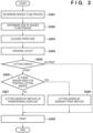
- FIG. 2 is a flowchart illustrating the operation of print processing of the printing apparatus 100.
- FIGS. 3A and 3B are diagrams illustrating examples of a screen displayed on the display unit 106 of the printing apparatus 100.
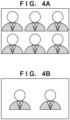
- FIGS. 4A and 4B are diagrams illustrating arrangement examples of images printed on a printing paper.
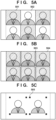
- FIGS. 5A to 5C are diagrams illustrating examples of cutting marks printed or formed on the printing paper.
- step S201 the CPU 101 determines one or more images to be printed among the images stored in the storage medium 104, on the basis of an instruction or selection by a user.
- FIG. 3A illustrates an example of a display screen of the display unit 106 when selecting an image to be printed.
- the display unit 106 is displaying an image 301 stored in the storage medium 104.
- the user can cause another image of the storage medium 104 to be displayed by operating the operation unit 105.
- the user can instruct the CPU 101 to perform printing (or selection as the premise thereof) of an image being displayed by operating, via the operation unit 105, a print button 302 displayed on the screen.
- the number of prints may be designated on the screen, and a plurality of images may be selected or set for the print target.
- step S202 the CPU 101 determines the size of the images to be printed, on the basis of an instruction or selection by the user.
- FIG. 3B illustrates an example of a setup screen for a certification photograph of the printing apparatus 100.
- the dimensions of long sides 303 and short sides 304 can be set as the settings of the certification photograph, which are to be applied.
- the user can select and set the dimensions of the long sides 303 and the short sides 304 by operating the operation unit 105.
- step S203 the CPU 101 acquires the size of the printing paper to be actually used for the printing from the paper feed unit 107 (printing paper size).
- the CPU 101 may display candidates for the size of the printing paper on the display unit 106 and allow the user to make a selection.
- the selection of the size of the printing paper may be done beforehand, or may be done each time printing is performed.
- step S204 the CPU 101 causes images of the number arrangeable on a single piece of printing paper to be arranged in a predetermined layout, on the basis of the size of the images which has been set in step S202 and the size of the printing paper which has been acquired in step S203.
- FIG. 4 illustrates the arrangement examples of images.
- images with the size, to be printed, of 50 mm ⁇ 50 mm are arranged on a printing paper having a size of 150 mm ⁇ 100 mm.
- Three images in the long side direction and two images in the short side direction can be arranged on the printing paper, where six images can be arranged on a single piece of printing paper.
- images with the size, to be printed, of 50 mm ⁇ 50 mm are arranged on a printing paper having a size of 120 mm ⁇ 90 mm.
- Two images in the long side direction and one image in the short side direction can be arranged on the printing paper, where two images can be arranged on a single piece of printing paper.
- step S205 the CPU 101 determines whether to print cutting marks, on the basis of an instruction or selection by the user.
- FIG. 3B illustrates an example of a setup screen for a certification photograph.
- the user can instruct the CPU 101 whether to print the selected images with or without cutting marks.
- "YES" is set as the initial value for a cutting mark 305.
- the user is allowed to set "None" (no cutting mark is to be printed) by operating the operation unit 105.
- the cutting mark represents a mark for assisting the user to cut off the printed images.
- step S206 the CPU 101 determines if there is a margin area for printing cutting marks. If there is no margin area for printing cutting marks, the CPU 101 causes the process to proceed to step S207. If there is a margin area for printing cutting marks, the CPU 101 causes the process to proceed to step S208. Note that, in the process of the step S206, a one-time determination may be performed on a single piece of printing paper, or a determination may be performed on each of the images to be arranged. Alternatively, when arranging images of the number arrangeable on a single piece of printing paper in step S204, the result of the determinations, which have been performed beforehand for all the arrangements, may be acquired.
- images with the size, to be printed, of 50 mm ⁇ 50 mm are arranged on a printing paper having a size of 150 mm ⁇ 100 mm.
- the margin from the paper end to the image end and between the images is 0 mm, and thus it is determined that there is no margin area for printing cutting marks.
- images with the size, to be printed, of 50 ⁇ 50 mm are arranged on a printing paper having a size of 120 mm ⁇ 90 mm.
- this layout there is a margin area of 20 mm in the long side direction of the printing paper, and a margin area of 40 mm in the short side direction, and thus it is determined that there is a margin area for printing cutting marks.
- step S207 the CPU 101 generates print data (gradation data) of overcoat so as to form cutting marks with varying methods, for each of the areas, of transferring the overcoat to be formed on the images. At this time, color inks are not used for forming the cutting marks.
- FIGS. 5A and 5B illustrate examples of cutting marks formed on the printing paper.
- a printing paper having a size of 150 mm ⁇ 100 mm is printed with images having the size, to be printed, of 50 mm ⁇ 50 mm, and the methods of transferring an overcoat are varied for each of the areas to thus form the cutting marks.
- An image area 501 has a specific pattern (for example, a checkered pattern) as the gradation of overcoat, while an image area 502 adjacent to the image area 501 has a single gradation as the gradation of overcoat.
- a printing paper having a size of 150 mm ⁇ 100 mm is printed with images having the size, to be printed, of 50 mm ⁇ 50 mm, and the methods of transferring an overcoat are varied for each of the areas to thus form the cutting marks.
- a cutting line area 503 has a single gradation as the gradation of overcoat, while the other areas 504 corresponding to the images have a specific pattern as the gradation of overcoat.
- the cutting line area 503 is made to be a non-transfer area of overcoat, while the other areas 504 may be made to have a single gradation as the gradation of overcoat. Further, the cutting line area 503 may have a specific pattern as the gradation of overcoat, while the other areas 504 may have another specific pattern as the gradation of overcoat. Moreover, the cutting line area 503 may have a specific pattern as the gradation of overcoat, while the other areas 504 may have a single gradation as the gradation of overcoat.
- the method of varying methods of transferring an overcoat for each of the areas to thus form cutting marks is not limited to the above methods, and may be any combination of these methods.
- step S208 the CPU 101 adds cutting marks to images laid out in S204 to perform printing of the cutting marks by an ordinary print method, that is, by using color inks.
- the overcoat is used with overcoat print data that includes no typical cutting marks because cutting marks are not printed.
- FIG. 5C illustrates an example of cutting marks printed on a printing paper.
- images having the size, to be printed, of 50 mm ⁇ 50 mm are printed on a printing paper having a size of 120 mm ⁇ 90 mm, where cutting marks 505 are printed by an ordinary print method.
- cutting marks 505 are arranged at the four corners of the image to be printed and then caused to be printed, the shapes and print positions of cutting marks are not limited to this, and cutting marks may be linear or a dashed line, or a plurality of dots. However, the cutting marks are printed outside of the image area of the images to be printed.
- step S209 the CPU 101 instructs the paper feed unit 107 to feed a printing paper and gives an instruction to the printing image unit 108, to thus cause printing to be performed onto the printing paper (print control).
- the CPU 101 converts the images laid out in S204 into print data (gradation data of colors) and gives an instruction to perform printing based on the print data.
- the CPU 101 converts the laid-out images to which cutting marks are added in S208 into print data (gradation data of colors), and gives an instruction to perform printing based on the print data.
- the CPU 101 For the printing of overcoat after the use of the color inks, in a case where it is determined to form cutting marks using overcoat in S207, the CPU 101 gives an instruction based on print data of overcoat (gradation data) including cutting marks, which have been generated in S207. While, in a case where it is determined in S208 to form cutting marks using color inks, the CPU 101 gives an instruction based on print data of overcoat (gradation data) that include no typical cutting marks.
- cutting marks cannot be printed by an ordinary method.
- FIGS. 5A and 5B by varying methods of transferring an overcoat for each of the areas, cutting marks can be formed although the visibility is lowered. That is, according to the first embodiment, the method of forming cutting marks is switched between the case where there is a margin area for printing cutting marks on the printing paper and the case where there is no margin area for printing cutting marks, thus making it possible to form cutting marks in either case.
- an integrated printing apparatus has been described as an example, the present invention is not limited to this embodiment.
- the present invention may be achieved by means of a system in which a printing apparatus including the paper feed unit 107 or the printing unit 108 is coupled to a control device configured to perform a control of determining a selection or layout of images and a control of operating the printing apparatus.
- the printing apparatus performs the print processing in S209, and the control device performs determination of a selection or arrangement of images in S201 to S208, for example.
- cutting marks are formed by varying methods of transferring an overcoat for each of the areas.
- the printing apparatus is a heat-transfer type printing apparatus similar to the first embodiment.
- the heat-transfer type printing apparatus is configured to perform printing on a recording paper having a cutting line such as a perforation for separating the print range from a non-print target (so-called tab area).
- the heat-transfer type printing apparatus which grips and transports a paper to perform printing thereon, needs tab areas on which printing is not to be performed.
- tab areas that inevitably occur in the heat-transfer printer are utilized, and cutting marks are formed in these tab areas.
- the block configuration of the printing apparatus according to the second embodiment is the same as the configuration of the first embodiment illustrated in FIG. 1 , and thus duplicate descriptions thereof will be omitted.
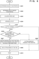
- FIG. 6 is a flowchart illustrating an operation of print processing of the printing apparatus 100 according to the second embodiment.
- the processes of steps S201 to S205 in FIG. 6 are the same as the processes of steps S201 to S205 in FIG. 2 , which illustrate the first embodiment, and thus duplicate descriptions thereof will be omitted.
- step S206 the CPU 101 determines if there is a margin area for printing cutting marks on the printing paper. If there is no margin area for printing cutting marks, the CPU 101 causes the process to proceed to step S607. If there is a margin area for printing cutting marks, the CPU 101 causes the process to proceed to step S608.
- step S607 for the images laid out in S204, the CPU 101 causes all the images to rotate such that the top direction of the images faces one of the short side directions of the printing paper.
- step S609 the CPU 101 adds cutting marks to the tab areas on the printing paper of the laid-out images for which the images have been rotated in S607.
- FIG. 7A illustrates an example of printing of cutting marks in tab areas 700 of the printing paper.
- the rotation of images in step S607 is due to the necessity of causing the cutting to be performed utilizing print marks because there are no marks for the cutting at the vertical line in cutting the certification photograph, as well as due to the easiness in cutting the paper because the demarcation of images is distinguishable, without the cutting marks, in the horizontal direction.
- Cutting marks 701 are printed at the central portions between the images in the tab areas 700.
- FIG. 7B illustrates an example of a pattern in which margin areas occur when images are laid out on the printing paper.
- the images are brought close to one of the long side directions to form a margin area 704, and cutting marks 702 and 703 are caused to be printed at two locations in the tab areas 700.
- the images are brought close, in the vertical direction of the images, toward one of the tab area to arrange a layout so as to form a margin area 705, to thereby eliminate the need for the cutting marks in the horizontal direction of the images.
- step S608 the CPU 101, which performs printing of cutting marks by an ordinary print method, adds cutting marks to the images laid out in S204.
- FIG. 7C illustrates an example of cutting marks printed on a printing paper.
- images having the size, to be printed, of 50 mm ⁇ 50 mm are printed on a printing paper having a size of 120 mm ⁇ 90 mm, where cutting marks 505 are printed by an ordinary print method.
- cutting marks 505 are arranged at the four corners of the image to be printed and then caused to be printed, the shapes and print positions of cutting marks are not limited to this, and cutting marks may be linear or a dashed line, or a plurality of dots. However, the cutting marks are printed outside of the image area of the images to be printed.
- step S610 the CPU 101 instructs the paper feed unit 107 to feed a printing paper and instructs the printing unit 108 to perform printing based on the print data onto the printing paper.
- the CPU 101 For the color inks, the CPU 101 generates print data (gradation data of colors) on the basis of the laid-out images generated in S204, and instructs performing printing on the basis of the generated print data.
- the CPU 101 generates print data on the basis of the laid-out images for which the images have been rotated or to which cutting marks are added, and instructs performing printing on the basis of the generated print data.
- the CPU 101 then instructs performing printing of overcoat on the basis of print data of overcoat that include no typical cutting marks.
- a selection may be made, as described below, between the forming of cutting marks by varying schemes of transferring an overcoat for each of the areas as in the first embodiment, and the printing of cutting marks in the tab areas.
- a scheme may be selected, in accordance with the size patterns of a certification photograph, such that, in a case where there are a plurality of size patterns of a certification photograph laid out on a printing paper, the scheme of transferring an overcoat is employed, while in a case where there are solely size patterns of the same type, printing of cutting marks in the tab areas is employed.
- the method of determination for the rotation of the images may include a method of causing the background hue of respective adjacent images to be different, or a method of determining the orientation of the images by performing face detection with an image recognition, to thus determine the top and bottom to perform a layout.
- a method may be employed in which the cutting position of the image is determined at the chest position in the image and the cutting marks are not caused to be printed, by arranging the respective adjacent images so that the images may not be equally oriented. For example, in a case of arranging three images on the long side direction and two images on the short side direction, a method may be employed in which the images on both short sides are arranged with one of the long side directions facing upwards, while the two central images are arranged with the different long side directions facing upward.
- Embodiment(s) of the present invention can also be realized by a computer of a system or apparatus that reads out and executes computer executable instructions (e.g., one or more programs) recorded on a storage medium (which may also be referred to more fully as a 'non-transitory computer-readable storage medium') to perform the functions of one or more of the above-described embodiment(s) and/or that includes one or more circuits (e.g., application specific integrated circuit (ASIC)) for performing the functions of one or more of the above-described embodiment(s), and by a method performed by the computer of the system or apparatus by, for example, reading out and executing the computer executable instructions from the storage medium to perform the functions of one or more of the above-described embodiment(s) and/or controlling the one or more circuits to perform the functions of one or more of the above-described embodiment(s).
- computer executable instructions e.g., one or more programs
- a storage medium which may also be referred to more fully as
- the computer may comprise one or more processors (e.g., central processing unit (CPU), micro processing unit (MPU)) and may include a network of separate computers or separate processors to read out and execute the computer executable instructions.
- the computer executable instructions may be provided to the computer, for example, from a network or the storage medium.
- the storage medium may include, for example, one or more of a hard disk, a random-access memory (RAM), a read only memory (ROM), a storage of distributed computing systems, an optical disk (such as a compact disc (CD), digital versatile disc (DVD), or Blu-ray Disc (BD) TM ), a flash memory device, a memory card, and the like.
- a print control device includes print control means configured to control, when laying out and performing printing of a plurality of images on a single piece of printing paper, printing of cutting marks serving as an aid for cutting off the plurality of images from the printing paper, wherein the print control means is configured to switch, in accordance with a layout of the plurality of images, whether the cutting marks are to be printed using color inks, or to be printed using transparent ink.
Landscapes
- Handling Of Sheets (AREA)
- Electronic Switches (AREA)
- Record Information Processing For Printing (AREA)
Applications Claiming Priority (1)
| Application Number | Priority Date | Filing Date | Title |
|---|---|---|---|
| JP2018159478A JP7137405B2 (ja) | 2018-08-28 | 2018-08-28 | 印刷装置及びその制御方法、プログラム、記憶媒体 |
Publications (2)
| Publication Number | Publication Date |
|---|---|
| EP3616934A1 EP3616934A1 (en) | 2020-03-04 |
| EP3616934B1 true EP3616934B1 (en) | 2023-07-05 |
Family
ID=67587511
Family Applications (1)
| Application Number | Title | Priority Date | Filing Date |
|---|---|---|---|
| EP19190776.5A Active EP3616934B1 (en) | 2018-08-28 | 2019-08-08 | Print control device for printing cutting marks, print control method, and storage medium |
Country Status (3)
| Country | Link |
|---|---|
| US (1) | US10913260B2 (enExample) |
| EP (1) | EP3616934B1 (enExample) |
| JP (1) | JP7137405B2 (enExample) |
Families Citing this family (1)
| Publication number | Priority date | Publication date | Assignee | Title |
|---|---|---|---|---|
| JP2025008769A (ja) * | 2023-07-06 | 2025-01-20 | 株式会社Screenホールディングス | 印刷データ生成装置、印刷データ生成方法、および印刷データ生成プログラム |
Family Cites Families (19)
| Publication number | Priority date | Publication date | Assignee | Title |
|---|---|---|---|---|
| JPH0927897A (ja) | 1995-05-09 | 1997-01-28 | Noritsu Koki Co Ltd | カットマーク入り証明写真及びその製造装置 |
| KR960042196A (ko) | 1995-05-09 | 1996-12-21 | 니시모토 강이치 | 자동촬영처리장치 및 자동촬영처리장치에 있어서 페이퍼반송장치 · 옥외설치용 박스 · 피사체촬영기구 및 커트마크가 들어있는 증명사진 |
| US5631747A (en) * | 1995-08-21 | 1997-05-20 | Xerox Corporation | Apparatus and method for applying trim marks to a print media sheet |
| US6765687B2 (en) * | 1998-09-10 | 2004-07-20 | Canon Kabushiki Kaisha | Image processing method and apparatus |
| JP3661749B2 (ja) * | 1998-09-21 | 2005-06-22 | セイコーエプソン株式会社 | 印刷制御装置、印刷制御方法および印刷制御プログラムを記録した媒体 |
| JP2000258849A (ja) | 1999-03-10 | 2000-09-22 | Noritsu Koki Co Ltd | 写真及びそのプリント処理装置 |
| JP4227263B2 (ja) * | 1999-10-12 | 2009-02-18 | キヤノン株式会社 | 画像処理装置、画像処理方法、及び、記憶媒体 |
| JP2002160410A (ja) | 2000-11-27 | 2002-06-04 | Noritsu Koki Co Ltd | インクジェット式プリンタ |
| US20020063879A1 (en) * | 2000-11-29 | 2002-05-30 | Eastman Kodak Company | Method and apparatus for reproducing an image with embedded cutting instructions and product thereof |
| JP2005088247A (ja) | 2003-09-12 | 2005-04-07 | Casio Comput Co Ltd | 印刷シート及び給紙トレイ |
| JP4198025B2 (ja) * | 2003-10-22 | 2008-12-17 | キヤノンファインテック株式会社 | 印字装置 |
| JP2006212997A (ja) * | 2005-02-07 | 2006-08-17 | Mimaki Engineering Co Ltd | インクジェットプリンタによる読み取り易いマークのプリント方法及びそれに用いるインクジェットプリンタ |
| JP2008136102A (ja) | 2006-11-29 | 2008-06-12 | Canon Software Inc | オブジェクト配置装置及び方法、プログラム、並びに記憶媒体 |
| JP5392542B2 (ja) * | 2009-02-27 | 2014-01-22 | カシオ計算機株式会社 | テープ印刷装置、切断印を有した印刷物の作成方法、切断印を有した印刷物の作成プログラムが記憶された記憶媒体 |
| JP2012135899A (ja) * | 2010-12-24 | 2012-07-19 | Konica Minolta Business Technologies Inc | 画像形成装置及び画像形成方法 |
| JP2012232530A (ja) | 2011-05-06 | 2012-11-29 | Canon Inc | 印刷装置 |
| US8923616B2 (en) * | 2011-07-29 | 2014-12-30 | Xerox Coporation | Image-content dependent print cutting system |
| JP6655987B2 (ja) | 2015-12-25 | 2020-03-04 | キヤノン株式会社 | 印刷制御装置及びその制御方法 |
| JP2018008366A (ja) * | 2016-06-29 | 2018-01-18 | ローランドディー.ジー.株式会社 | カッティング装置およびカッティング方法 |
-
2018
- 2018-08-28 JP JP2018159478A patent/JP7137405B2/ja active Active
-
2019
- 2019-08-08 EP EP19190776.5A patent/EP3616934B1/en active Active
- 2019-08-27 US US16/552,504 patent/US10913260B2/en active Active
Also Published As
| Publication number | Publication date |
|---|---|
| US20200070495A1 (en) | 2020-03-05 |
| JP2020032577A (ja) | 2020-03-05 |
| EP3616934A1 (en) | 2020-03-04 |
| JP7137405B2 (ja) | 2022-09-14 |
| US10913260B2 (en) | 2021-02-09 |
Similar Documents
| Publication | Publication Date | Title |
|---|---|---|
| CN105282355B (zh) | 图像处理设备和图像处理方法 | |
| JP7024390B2 (ja) | 印刷装置、印刷システムおよびプログラム | |
| US7317551B2 (en) | Method and apparatus for tab sheet printing | |
| US11650778B2 (en) | Control method, information processing apparatus, and print system | |
| CN111716922B (zh) | 打印机和打印系统 | |
| US10913260B2 (en) | Print control device, print control method, and storage medium | |
| JP2009033530A (ja) | 画像形成装置 | |
| JP2012232530A (ja) | 印刷装置 | |
| US11789390B2 (en) | Systems and methods for arranging adjacent pages based on print data associated with the pages | |
| JP4904987B2 (ja) | 印刷方法、印刷装置および印刷プログラム | |
| JP2006137155A (ja) | カラー画像形成装置および方法ならびに画像処理プログラム | |
| JP6950372B2 (ja) | 印刷データ生成プログラムおよび印刷データ生成装置 | |
| JP2016119546A (ja) | 画像処理装置、画像処理方法 | |
| JP7409161B2 (ja) | 情報処理装置、情報処理方法及びプログラム | |
| JP7089220B2 (ja) | 制御プログラム、および情報処理装置 | |
| US12432305B2 (en) | System and method for controlling label printing | |
| JP2020032577A5 (enExample) | ||
| JP2007118221A (ja) | 印刷装置、印刷処理プログラム、及び印刷処理システム | |
| JP2006040218A (ja) | 記録システム | |
| JPH1058787A (ja) | 印刷処理方法および装置 | |
| JP2024043423A (ja) | プログラム、情報処理装置の制御方法及び情報処理装置 | |
| JP2012058452A (ja) | 画像形成装置、その制御方法、及び制御プログラム | |
| JP2021117413A (ja) | 画像形成装置および画像形成方法 | |
| JP2010076098A (ja) | ラベル印刷装置 | |
| JP2017118429A (ja) | 印刷装置及びその制御方法 |
Legal Events
| Date | Code | Title | Description |
|---|---|---|---|
| PUAI | Public reference made under article 153(3) epc to a published international application that has entered the european phase |
Free format text: ORIGINAL CODE: 0009012 |
|
| STAA | Information on the status of an ep patent application or granted ep patent |
Free format text: STATUS: THE APPLICATION HAS BEEN PUBLISHED |
|
| AK | Designated contracting states |
Kind code of ref document: A1 Designated state(s): AL AT BE BG CH CY CZ DE DK EE ES FI FR GB GR HR HU IE IS IT LI LT LU LV MC MK MT NL NO PL PT RO RS SE SI SK SM TR |
|
| AX | Request for extension of the european patent |
Extension state: BA ME |
|
| STAA | Information on the status of an ep patent application or granted ep patent |
Free format text: STATUS: REQUEST FOR EXAMINATION WAS MADE |
|
| 17P | Request for examination filed |
Effective date: 20200904 |
|
| RBV | Designated contracting states (corrected) |
Designated state(s): AL AT BE BG CH CY CZ DE DK EE ES FI FR GB GR HR HU IE IS IT LI LT LU LV MC MK MT NL NO PL PT RO RS SE SI SK SM TR |
|
| STAA | Information on the status of an ep patent application or granted ep patent |
Free format text: STATUS: EXAMINATION IS IN PROGRESS |
|
| 17Q | First examination report despatched |
Effective date: 20220516 |
|
| GRAP | Despatch of communication of intention to grant a patent |
Free format text: ORIGINAL CODE: EPIDOSNIGR1 |
|
| STAA | Information on the status of an ep patent application or granted ep patent |
Free format text: STATUS: GRANT OF PATENT IS INTENDED |
|
| INTG | Intention to grant announced |
Effective date: 20230130 |
|
| GRAS | Grant fee paid |
Free format text: ORIGINAL CODE: EPIDOSNIGR3 |
|
| GRAA | (expected) grant |
Free format text: ORIGINAL CODE: 0009210 |
|
| STAA | Information on the status of an ep patent application or granted ep patent |
Free format text: STATUS: THE PATENT HAS BEEN GRANTED |
|
| AK | Designated contracting states |
Kind code of ref document: B1 Designated state(s): AL AT BE BG CH CY CZ DE DK EE ES FI FR GB GR HR HU IE IS IT LI LT LU LV MC MK MT NL NO PL PT RO RS SE SI SK SM TR |
|
| REG | Reference to a national code |
Ref country code: CH Ref legal event code: EP |
|
| REG | Reference to a national code |
Ref country code: AT Ref legal event code: REF Ref document number: 1584513 Country of ref document: AT Kind code of ref document: T Effective date: 20230715 |
|
| REG | Reference to a national code |
Ref country code: DE Ref legal event code: R096 Ref document number: 602019032024 Country of ref document: DE |
|
| REG | Reference to a national code |
Ref country code: IE Ref legal event code: FG4D |
|
| REG | Reference to a national code |
Ref country code: LT Ref legal event code: MG9D |
|
| REG | Reference to a national code |
Ref country code: NL Ref legal event code: MP Effective date: 20230705 |
|
| REG | Reference to a national code |
Ref country code: AT Ref legal event code: MK05 Ref document number: 1584513 Country of ref document: AT Kind code of ref document: T Effective date: 20230705 |
|
| PG25 | Lapsed in a contracting state [announced via postgrant information from national office to epo] |
Ref country code: NL Free format text: LAPSE BECAUSE OF FAILURE TO SUBMIT A TRANSLATION OF THE DESCRIPTION OR TO PAY THE FEE WITHIN THE PRESCRIBED TIME-LIMIT Effective date: 20230705 |
|
| PG25 | Lapsed in a contracting state [announced via postgrant information from national office to epo] |
Ref country code: GR Free format text: LAPSE BECAUSE OF FAILURE TO SUBMIT A TRANSLATION OF THE DESCRIPTION OR TO PAY THE FEE WITHIN THE PRESCRIBED TIME-LIMIT Effective date: 20231006 |
|
| PG25 | Lapsed in a contracting state [announced via postgrant information from national office to epo] |
Ref country code: ES Free format text: LAPSE BECAUSE OF FAILURE TO SUBMIT A TRANSLATION OF THE DESCRIPTION OR TO PAY THE FEE WITHIN THE PRESCRIBED TIME-LIMIT Effective date: 20230705 |
|
| PG25 | Lapsed in a contracting state [announced via postgrant information from national office to epo] |
Ref country code: IS Free format text: LAPSE BECAUSE OF FAILURE TO SUBMIT A TRANSLATION OF THE DESCRIPTION OR TO PAY THE FEE WITHIN THE PRESCRIBED TIME-LIMIT Effective date: 20231105 |
|
| PG25 | Lapsed in a contracting state [announced via postgrant information from national office to epo] |
Ref country code: SE Free format text: LAPSE BECAUSE OF FAILURE TO SUBMIT A TRANSLATION OF THE DESCRIPTION OR TO PAY THE FEE WITHIN THE PRESCRIBED TIME-LIMIT Effective date: 20230705 Ref country code: RS Free format text: LAPSE BECAUSE OF FAILURE TO SUBMIT A TRANSLATION OF THE DESCRIPTION OR TO PAY THE FEE WITHIN THE PRESCRIBED TIME-LIMIT Effective date: 20230705 Ref country code: PT Free format text: LAPSE BECAUSE OF FAILURE TO SUBMIT A TRANSLATION OF THE DESCRIPTION OR TO PAY THE FEE WITHIN THE PRESCRIBED TIME-LIMIT Effective date: 20231106 Ref country code: NO Free format text: LAPSE BECAUSE OF FAILURE TO SUBMIT A TRANSLATION OF THE DESCRIPTION OR TO PAY THE FEE WITHIN THE PRESCRIBED TIME-LIMIT Effective date: 20231005 Ref country code: LV Free format text: LAPSE BECAUSE OF FAILURE TO SUBMIT A TRANSLATION OF THE DESCRIPTION OR TO PAY THE FEE WITHIN THE PRESCRIBED TIME-LIMIT Effective date: 20230705 Ref country code: LT Free format text: LAPSE BECAUSE OF FAILURE TO SUBMIT A TRANSLATION OF THE DESCRIPTION OR TO PAY THE FEE WITHIN THE PRESCRIBED TIME-LIMIT Effective date: 20230705 Ref country code: IS Free format text: LAPSE BECAUSE OF FAILURE TO SUBMIT A TRANSLATION OF THE DESCRIPTION OR TO PAY THE FEE WITHIN THE PRESCRIBED TIME-LIMIT Effective date: 20231105 Ref country code: HR Free format text: LAPSE BECAUSE OF FAILURE TO SUBMIT A TRANSLATION OF THE DESCRIPTION OR TO PAY THE FEE WITHIN THE PRESCRIBED TIME-LIMIT Effective date: 20230705 Ref country code: GR Free format text: LAPSE BECAUSE OF FAILURE TO SUBMIT A TRANSLATION OF THE DESCRIPTION OR TO PAY THE FEE WITHIN THE PRESCRIBED TIME-LIMIT Effective date: 20231006 Ref country code: FI Free format text: LAPSE BECAUSE OF FAILURE TO SUBMIT A TRANSLATION OF THE DESCRIPTION OR TO PAY THE FEE WITHIN THE PRESCRIBED TIME-LIMIT Effective date: 20230705 Ref country code: ES Free format text: LAPSE BECAUSE OF FAILURE TO SUBMIT A TRANSLATION OF THE DESCRIPTION OR TO PAY THE FEE WITHIN THE PRESCRIBED TIME-LIMIT Effective date: 20230705 Ref country code: AT Free format text: LAPSE BECAUSE OF FAILURE TO SUBMIT A TRANSLATION OF THE DESCRIPTION OR TO PAY THE FEE WITHIN THE PRESCRIBED TIME-LIMIT Effective date: 20230705 |
|
| PG25 | Lapsed in a contracting state [announced via postgrant information from national office to epo] |
Ref country code: PL Free format text: LAPSE BECAUSE OF FAILURE TO SUBMIT A TRANSLATION OF THE DESCRIPTION OR TO PAY THE FEE WITHIN THE PRESCRIBED TIME-LIMIT Effective date: 20230705 |
|
| REG | Reference to a national code |
Ref country code: CH Ref legal event code: PL |
|
| REG | Reference to a national code |
Ref country code: DE Ref legal event code: R097 Ref document number: 602019032024 Country of ref document: DE |
|
| PG25 | Lapsed in a contracting state [announced via postgrant information from national office to epo] |
Ref country code: LU Free format text: LAPSE BECAUSE OF NON-PAYMENT OF DUE FEES Effective date: 20230808 |
|
| PG25 | Lapsed in a contracting state [announced via postgrant information from national office to epo] |
Ref country code: SM Free format text: LAPSE BECAUSE OF FAILURE TO SUBMIT A TRANSLATION OF THE DESCRIPTION OR TO PAY THE FEE WITHIN THE PRESCRIBED TIME-LIMIT Effective date: 20230705 Ref country code: RO Free format text: LAPSE BECAUSE OF FAILURE TO SUBMIT A TRANSLATION OF THE DESCRIPTION OR TO PAY THE FEE WITHIN THE PRESCRIBED TIME-LIMIT Effective date: 20230705 Ref country code: LU Free format text: LAPSE BECAUSE OF NON-PAYMENT OF DUE FEES Effective date: 20230808 Ref country code: EE Free format text: LAPSE BECAUSE OF FAILURE TO SUBMIT A TRANSLATION OF THE DESCRIPTION OR TO PAY THE FEE WITHIN THE PRESCRIBED TIME-LIMIT Effective date: 20230705 Ref country code: DK Free format text: LAPSE BECAUSE OF FAILURE TO SUBMIT A TRANSLATION OF THE DESCRIPTION OR TO PAY THE FEE WITHIN THE PRESCRIBED TIME-LIMIT Effective date: 20230705 Ref country code: CZ Free format text: LAPSE BECAUSE OF FAILURE TO SUBMIT A TRANSLATION OF THE DESCRIPTION OR TO PAY THE FEE WITHIN THE PRESCRIBED TIME-LIMIT Effective date: 20230705 Ref country code: CH Free format text: LAPSE BECAUSE OF NON-PAYMENT OF DUE FEES Effective date: 20230831 Ref country code: MC Free format text: LAPSE BECAUSE OF FAILURE TO SUBMIT A TRANSLATION OF THE DESCRIPTION OR TO PAY THE FEE WITHIN THE PRESCRIBED TIME-LIMIT Effective date: 20230705 Ref country code: SK Free format text: LAPSE BECAUSE OF FAILURE TO SUBMIT A TRANSLATION OF THE DESCRIPTION OR TO PAY THE FEE WITHIN THE PRESCRIBED TIME-LIMIT Effective date: 20230705 |
|
| REG | Reference to a national code |
Ref country code: BE Ref legal event code: MM Effective date: 20230831 |
|
| PLBE | No opposition filed within time limit |
Free format text: ORIGINAL CODE: 0009261 |
|
| STAA | Information on the status of an ep patent application or granted ep patent |
Free format text: STATUS: NO OPPOSITION FILED WITHIN TIME LIMIT |
|
| REG | Reference to a national code |
Ref country code: IE Ref legal event code: MM4A |
|
| PG25 | Lapsed in a contracting state [announced via postgrant information from national office to epo] |
Ref country code: IT Free format text: LAPSE BECAUSE OF FAILURE TO SUBMIT A TRANSLATION OF THE DESCRIPTION OR TO PAY THE FEE WITHIN THE PRESCRIBED TIME-LIMIT Effective date: 20230705 |
|
| 26N | No opposition filed |
Effective date: 20240408 |
|
| GBPC | Gb: european patent ceased through non-payment of renewal fee |
Effective date: 20231005 |
|
| PG25 | Lapsed in a contracting state [announced via postgrant information from national office to epo] |
Ref country code: IE Free format text: LAPSE BECAUSE OF NON-PAYMENT OF DUE FEES Effective date: 20230808 |
|
| PG25 | Lapsed in a contracting state [announced via postgrant information from national office to epo] |
Ref country code: GB Free format text: LAPSE BECAUSE OF NON-PAYMENT OF DUE FEES Effective date: 20231005 |
|
| PG25 | Lapsed in a contracting state [announced via postgrant information from national office to epo] |
Ref country code: IE Free format text: LAPSE BECAUSE OF NON-PAYMENT OF DUE FEES Effective date: 20230808 Ref country code: GB Free format text: LAPSE BECAUSE OF NON-PAYMENT OF DUE FEES Effective date: 20231005 Ref country code: FR Free format text: LAPSE BECAUSE OF NON-PAYMENT OF DUE FEES Effective date: 20230905 Ref country code: SI Free format text: LAPSE BECAUSE OF FAILURE TO SUBMIT A TRANSLATION OF THE DESCRIPTION OR TO PAY THE FEE WITHIN THE PRESCRIBED TIME-LIMIT Effective date: 20230705 |
|
| PG25 | Lapsed in a contracting state [announced via postgrant information from national office to epo] |
Ref country code: BE Free format text: LAPSE BECAUSE OF NON-PAYMENT OF DUE FEES Effective date: 20230831 |
|
| PG25 | Lapsed in a contracting state [announced via postgrant information from national office to epo] |
Ref country code: BG Free format text: LAPSE BECAUSE OF FAILURE TO SUBMIT A TRANSLATION OF THE DESCRIPTION OR TO PAY THE FEE WITHIN THE PRESCRIBED TIME-LIMIT Effective date: 20230705 |
|
| PG25 | Lapsed in a contracting state [announced via postgrant information from national office to epo] |
Ref country code: BG Free format text: LAPSE BECAUSE OF FAILURE TO SUBMIT A TRANSLATION OF THE DESCRIPTION OR TO PAY THE FEE WITHIN THE PRESCRIBED TIME-LIMIT Effective date: 20230705 |
|
| PG25 | Lapsed in a contracting state [announced via postgrant information from national office to epo] |
Ref country code: CY Free format text: LAPSE BECAUSE OF FAILURE TO SUBMIT A TRANSLATION OF THE DESCRIPTION OR TO PAY THE FEE WITHIN THE PRESCRIBED TIME-LIMIT; INVALID AB INITIO Effective date: 20190808 |
|
| PG25 | Lapsed in a contracting state [announced via postgrant information from national office to epo] |
Ref country code: HU Free format text: LAPSE BECAUSE OF FAILURE TO SUBMIT A TRANSLATION OF THE DESCRIPTION OR TO PAY THE FEE WITHIN THE PRESCRIBED TIME-LIMIT; INVALID AB INITIO Effective date: 20190808 |
|
| PGFP | Annual fee paid to national office [announced via postgrant information from national office to epo] |
Ref country code: DE Payment date: 20250724 Year of fee payment: 7 |
|
| PG25 | Lapsed in a contracting state [announced via postgrant information from national office to epo] |
Ref country code: TR Free format text: LAPSE BECAUSE OF FAILURE TO SUBMIT A TRANSLATION OF THE DESCRIPTION OR TO PAY THE FEE WITHIN THE PRESCRIBED TIME-LIMIT Effective date: 20230705 |