EP3616636B1 - Knochenplatte und chirurgische sets - Google Patents
Knochenplatte und chirurgische sets Download PDFInfo
- Publication number
- EP3616636B1 EP3616636B1 EP19203806.5A EP19203806A EP3616636B1 EP 3616636 B1 EP3616636 B1 EP 3616636B1 EP 19203806 A EP19203806 A EP 19203806A EP 3616636 B1 EP3616636 B1 EP 3616636B1
- Authority
- EP
- European Patent Office
- Prior art keywords
- bone
- bone plate
- screw
- bone screw
- opening
- Prior art date
- Legal status (The legal status is an assumption and is not a legal conclusion. Google has not performed a legal analysis and makes no representation as to the accuracy of the status listed.)
- Active
Links
- 210000000988 bone and bone Anatomy 0.000 title claims description 346
- 238000005452 bending Methods 0.000 claims description 74
- 230000001174 ascending effect Effects 0.000 claims description 18
- 210000004373 mandible Anatomy 0.000 claims description 10
- 208000014674 injury Diseases 0.000 claims description 7
- 230000008733 trauma Effects 0.000 claims description 4
- 230000007547 defect Effects 0.000 description 33
- 210000001847 jaw Anatomy 0.000 description 21
- 210000003484 anatomy Anatomy 0.000 description 14
- 239000000463 material Substances 0.000 description 11
- 206010017076 Fracture Diseases 0.000 description 9
- 239000007943 implant Substances 0.000 description 8
- 210000001738 temporomandibular joint Anatomy 0.000 description 8
- 230000006641 stabilisation Effects 0.000 description 7
- 238000011105 stabilization Methods 0.000 description 7
- RTAQQCXQSZGOHL-UHFFFAOYSA-N Titanium Chemical compound [Ti] RTAQQCXQSZGOHL-UHFFFAOYSA-N 0.000 description 6
- 230000000903 blocking effect Effects 0.000 description 6
- 230000001055 chewing effect Effects 0.000 description 6
- 239000010936 titanium Substances 0.000 description 6
- 229910052719 titanium Inorganic materials 0.000 description 6
- 208000010392 Bone Fractures Diseases 0.000 description 5
- 230000000149 penetrating effect Effects 0.000 description 5
- 230000006378 damage Effects 0.000 description 4
- 230000009747 swallowing Effects 0.000 description 4
- 208000027418 Wounds and injury Diseases 0.000 description 3
- 238000005520 cutting process Methods 0.000 description 3
- 210000002683 foot Anatomy 0.000 description 3
- 238000003860 storage Methods 0.000 description 3
- 238000005482 strain hardening Methods 0.000 description 3
- 210000001519 tissue Anatomy 0.000 description 3
- 241001136792 Alle Species 0.000 description 2
- 208000006153 Mandibular Fractures Diseases 0.000 description 2
- 229910000831 Steel Inorganic materials 0.000 description 2
- 230000006978 adaptation Effects 0.000 description 2
- 229910045601 alloy Inorganic materials 0.000 description 2
- 239000000956 alloy Substances 0.000 description 2
- 230000015572 biosynthetic process Effects 0.000 description 2
- 230000008468 bone growth Effects 0.000 description 2
- 239000000919 ceramic Substances 0.000 description 2
- 238000009826 distribution Methods 0.000 description 2
- 239000012634 fragment Substances 0.000 description 2
- 238000004519 manufacturing process Methods 0.000 description 2
- 210000001872 metatarsal bone Anatomy 0.000 description 2
- 238000000034 method Methods 0.000 description 2
- 210000004872 soft tissue Anatomy 0.000 description 2
- 239000007787 solid Substances 0.000 description 2
- 239000010959 steel Substances 0.000 description 2
- 210000004233 talus Anatomy 0.000 description 2
- 208000024779 Comminuted Fractures Diseases 0.000 description 1
- 206010027677 Fractures and dislocations Diseases 0.000 description 1
- 206010028980 Neoplasm Diseases 0.000 description 1
- 206010031264 Osteonecrosis Diseases 0.000 description 1
- 206010065769 Soft tissue necrosis Diseases 0.000 description 1
- 229910001069 Ti alloy Inorganic materials 0.000 description 1
- 230000004308 accommodation Effects 0.000 description 1
- 238000004873 anchoring Methods 0.000 description 1
- 238000013459 approach Methods 0.000 description 1
- 230000015556 catabolic process Effects 0.000 description 1
- 230000008878 coupling Effects 0.000 description 1
- 238000010168 coupling process Methods 0.000 description 1
- 238000005859 coupling reaction Methods 0.000 description 1
- 210000000460 cuneiform bone Anatomy 0.000 description 1
- 238000006731 degradation reaction Methods 0.000 description 1
- 230000005484 gravity Effects 0.000 description 1
- 210000003128 head Anatomy 0.000 description 1
- 238000003780 insertion Methods 0.000 description 1
- 230000037431 insertion Effects 0.000 description 1
- 230000007794 irritation Effects 0.000 description 1
- 229910052751 metal Inorganic materials 0.000 description 1
- 239000002184 metal Substances 0.000 description 1
- 238000000465 moulding Methods 0.000 description 1
- 210000000214 mouth Anatomy 0.000 description 1
- 210000000450 navicular bone Anatomy 0.000 description 1
- 230000001097 osteosynthetic effect Effects 0.000 description 1
- 239000011049 pearl Substances 0.000 description 1
- 230000002093 peripheral effect Effects 0.000 description 1
- 230000002980 postoperative effect Effects 0.000 description 1
- 230000001737 promoting effect Effects 0.000 description 1
- 230000005855 radiation Effects 0.000 description 1
- 238000007493 shaping process Methods 0.000 description 1
- 230000001225 therapeutic effect Effects 0.000 description 1
Images


Classifications
-
- A—HUMAN NECESSITIES
- A61—MEDICAL OR VETERINARY SCIENCE; HYGIENE
- A61B—DIAGNOSIS; SURGERY; IDENTIFICATION
- A61B17/00—Surgical instruments, devices or methods, e.g. tourniquets
- A61B17/56—Surgical instruments or methods for treatment of bones or joints; Devices specially adapted therefor
- A61B17/58—Surgical instruments or methods for treatment of bones or joints; Devices specially adapted therefor for osteosynthesis, e.g. bone plates, screws, setting implements or the like
- A61B17/68—Internal fixation devices, including fasteners and spinal fixators, even if a part thereof projects from the skin
- A61B17/683—Internal fixation devices, including fasteners and spinal fixators, even if a part thereof projects from the skin comprising bone transfixation elements, e.g. bolt with a distal cooperating element such as a nut
-
- A—HUMAN NECESSITIES
- A61—MEDICAL OR VETERINARY SCIENCE; HYGIENE
- A61B—DIAGNOSIS; SURGERY; IDENTIFICATION
- A61B17/00—Surgical instruments, devices or methods, e.g. tourniquets
- A61B17/56—Surgical instruments or methods for treatment of bones or joints; Devices specially adapted therefor
- A61B17/58—Surgical instruments or methods for treatment of bones or joints; Devices specially adapted therefor for osteosynthesis, e.g. bone plates, screws, setting implements or the like
- A61B17/68—Internal fixation devices, including fasteners and spinal fixators, even if a part thereof projects from the skin
- A61B17/80—Cortical plates, i.e. bone plates; Instruments for holding or positioning cortical plates, or for compressing bones attached to cortical plates
- A61B17/8052—Cortical plates, i.e. bone plates; Instruments for holding or positioning cortical plates, or for compressing bones attached to cortical plates immobilised relative to screws by interlocking form of the heads and plate holes, e.g. conical or threaded
-
- A—HUMAN NECESSITIES
- A61—MEDICAL OR VETERINARY SCIENCE; HYGIENE
- A61B—DIAGNOSIS; SURGERY; IDENTIFICATION
- A61B17/00—Surgical instruments, devices or methods, e.g. tourniquets
- A61B17/56—Surgical instruments or methods for treatment of bones or joints; Devices specially adapted therefor
- A61B17/58—Surgical instruments or methods for treatment of bones or joints; Devices specially adapted therefor for osteosynthesis, e.g. bone plates, screws, setting implements or the like
- A61B17/68—Internal fixation devices, including fasteners and spinal fixators, even if a part thereof projects from the skin
- A61B17/80—Cortical plates, i.e. bone plates; Instruments for holding or positioning cortical plates, or for compressing bones attached to cortical plates
- A61B17/8061—Cortical plates, i.e. bone plates; Instruments for holding or positioning cortical plates, or for compressing bones attached to cortical plates specially adapted for particular bones
- A61B17/8071—Cortical plates, i.e. bone plates; Instruments for holding or positioning cortical plates, or for compressing bones attached to cortical plates specially adapted for particular bones for the jaw
-
- A—HUMAN NECESSITIES
- A61—MEDICAL OR VETERINARY SCIENCE; HYGIENE
- A61B—DIAGNOSIS; SURGERY; IDENTIFICATION
- A61B17/00—Surgical instruments, devices or methods, e.g. tourniquets
- A61B17/56—Surgical instruments or methods for treatment of bones or joints; Devices specially adapted therefor
- A61B17/58—Surgical instruments or methods for treatment of bones or joints; Devices specially adapted therefor for osteosynthesis, e.g. bone plates, screws, setting implements or the like
- A61B17/68—Internal fixation devices, including fasteners and spinal fixators, even if a part thereof projects from the skin
- A61B17/80—Cortical plates, i.e. bone plates; Instruments for holding or positioning cortical plates, or for compressing bones attached to cortical plates
- A61B17/8085—Cortical plates, i.e. bone plates; Instruments for holding or positioning cortical plates, or for compressing bones attached to cortical plates with pliable or malleable elements or having a mesh-like structure, e.g. small strips
-
- A—HUMAN NECESSITIES
- A61—MEDICAL OR VETERINARY SCIENCE; HYGIENE
- A61B—DIAGNOSIS; SURGERY; IDENTIFICATION
- A61B17/00—Surgical instruments, devices or methods, e.g. tourniquets
- A61B17/56—Surgical instruments or methods for treatment of bones or joints; Devices specially adapted therefor
- A61B17/58—Surgical instruments or methods for treatment of bones or joints; Devices specially adapted therefor for osteosynthesis, e.g. bone plates, screws, setting implements or the like
- A61B17/68—Internal fixation devices, including fasteners and spinal fixators, even if a part thereof projects from the skin
- A61B17/84—Fasteners therefor or fasteners being internal fixation devices
- A61B17/86—Pins or screws or threaded wires; nuts therefor
- A61B17/8625—Shanks, i.e. parts contacting bone tissue
- A61B17/8635—Tips of screws
-
- A—HUMAN NECESSITIES
- A61—MEDICAL OR VETERINARY SCIENCE; HYGIENE
- A61B—DIAGNOSIS; SURGERY; IDENTIFICATION
- A61B17/00—Surgical instruments, devices or methods, e.g. tourniquets
- A61B17/56—Surgical instruments or methods for treatment of bones or joints; Devices specially adapted therefor
- A61B17/58—Surgical instruments or methods for treatment of bones or joints; Devices specially adapted therefor for osteosynthesis, e.g. bone plates, screws, setting implements or the like
- A61B17/68—Internal fixation devices, including fasteners and spinal fixators, even if a part thereof projects from the skin
- A61B17/84—Fasteners therefor or fasteners being internal fixation devices
- A61B17/86—Pins or screws or threaded wires; nuts therefor
- A61B17/8645—Headless screws, e.g. ligament interference screws
-
- A—HUMAN NECESSITIES
- A61—MEDICAL OR VETERINARY SCIENCE; HYGIENE
- A61F—FILTERS IMPLANTABLE INTO BLOOD VESSELS; PROSTHESES; DEVICES PROVIDING PATENCY TO, OR PREVENTING COLLAPSING OF, TUBULAR STRUCTURES OF THE BODY, e.g. STENTS; ORTHOPAEDIC, NURSING OR CONTRACEPTIVE DEVICES; FOMENTATION; TREATMENT OR PROTECTION OF EYES OR EARS; BANDAGES, DRESSINGS OR ABSORBENT PADS; FIRST-AID KITS
- A61F2/00—Filters implantable into blood vessels; Prostheses, i.e. artificial substitutes or replacements for parts of the body; Appliances for connecting them with the body; Devices providing patency to, or preventing collapsing of, tubular structures of the body, e.g. stents
- A61F2/02—Prostheses implantable into the body
- A61F2/28—Bones
- A61F2/2803—Bones for mandibular reconstruction
-
- A—HUMAN NECESSITIES
- A61—MEDICAL OR VETERINARY SCIENCE; HYGIENE
- A61B—DIAGNOSIS; SURGERY; IDENTIFICATION
- A61B17/00—Surgical instruments, devices or methods, e.g. tourniquets
- A61B17/56—Surgical instruments or methods for treatment of bones or joints; Devices specially adapted therefor
- A61B17/58—Surgical instruments or methods for treatment of bones or joints; Devices specially adapted therefor for osteosynthesis, e.g. bone plates, screws, setting implements or the like
- A61B17/68—Internal fixation devices, including fasteners and spinal fixators, even if a part thereof projects from the skin
- A61B17/80—Cortical plates, i.e. bone plates; Instruments for holding or positioning cortical plates, or for compressing bones attached to cortical plates
- A61B17/8052—Cortical plates, i.e. bone plates; Instruments for holding or positioning cortical plates, or for compressing bones attached to cortical plates immobilised relative to screws by interlocking form of the heads and plate holes, e.g. conical or threaded
- A61B17/8057—Cortical plates, i.e. bone plates; Instruments for holding or positioning cortical plates, or for compressing bones attached to cortical plates immobilised relative to screws by interlocking form of the heads and plate holes, e.g. conical or threaded the interlocking form comprising a thread
-
- A—HUMAN NECESSITIES
- A61—MEDICAL OR VETERINARY SCIENCE; HYGIENE
- A61B—DIAGNOSIS; SURGERY; IDENTIFICATION
- A61B17/00—Surgical instruments, devices or methods, e.g. tourniquets
- A61B17/56—Surgical instruments or methods for treatment of bones or joints; Devices specially adapted therefor
- A61B17/58—Surgical instruments or methods for treatment of bones or joints; Devices specially adapted therefor for osteosynthesis, e.g. bone plates, screws, setting implements or the like
- A61B17/68—Internal fixation devices, including fasteners and spinal fixators, even if a part thereof projects from the skin
- A61B17/84—Fasteners therefor or fasteners being internal fixation devices
- A61B17/86—Pins or screws or threaded wires; nuts therefor
- A61B2017/8655—Pins or screws or threaded wires; nuts therefor with special features for locking in the bone
-
- A—HUMAN NECESSITIES
- A61—MEDICAL OR VETERINARY SCIENCE; HYGIENE
- A61F—FILTERS IMPLANTABLE INTO BLOOD VESSELS; PROSTHESES; DEVICES PROVIDING PATENCY TO, OR PREVENTING COLLAPSING OF, TUBULAR STRUCTURES OF THE BODY, e.g. STENTS; ORTHOPAEDIC, NURSING OR CONTRACEPTIVE DEVICES; FOMENTATION; TREATMENT OR PROTECTION OF EYES OR EARS; BANDAGES, DRESSINGS OR ABSORBENT PADS; FIRST-AID KITS
- A61F2/00—Filters implantable into blood vessels; Prostheses, i.e. artificial substitutes or replacements for parts of the body; Appliances for connecting them with the body; Devices providing patency to, or preventing collapsing of, tubular structures of the body, e.g. stents
- A61F2/02—Prostheses implantable into the body
- A61F2/28—Bones
- A61F2/2803—Bones for mandibular reconstruction
- A61F2002/2807—Chin implants
Definitions
- the present invention relates to bone screws according to the preamble of claim 1 and to surgical sets containing a bone plate and such a bone screw.
- Bone plates of this type can be used, for example, to bridge a bone defect or to treat a fracture.
- bone plates for reconstruction or trauma treatment of a human mandible are disclosed herein.
- the aspect of the invention relates to a bone screw which contains a first end which has an engagement contour and a second end opposite the first end which has a locking element.
- a bone screw with these features of the preamble of claim 1 is from U.S. 2009/312802 A1 known.
- Another bone screw is from the U.S. 2013/096559 A1 known.
- the locking element of the bone screw is designed in such a way that it can be fixed at different angles relative to a bone plate.
- Advantages of such a blocking element result in particular from the Figures 11a to 13c illustrated embodiments. In the following it is described by way of example for which purposes and with which bone plates the bone screws according to the invention can be used.
- a generic bone plate for a human lower jaw is, for example, from WO 01/82809 known. with such plates
- weakened, receding bone structures of a lower jaw can be reinforced. Bone structures of this kind can arise when a tumor is removed, for example, or as a result of an injury, for example a gunshot.
- the bone plate should be able to withstand the daily stresses that occur, for example, when chewing or swallowing, over a long period of time.
- a hard material is usually used, such as grade 4 titanium. Titanium of this grade is very hard and therefore stiff against bending, but it is also relatively brittle.
- the anatomy of human bones and in particular a human lower jaw is very different from person to person.
- the distance between the jaw angle, which is formed between the ascending branch and the horizontal branch, and the center of the chin varies, for example depending on the age, height and sex of the patient.
- Due to the individually occurring variations in bone shape, especially in the human lower jaw, anatomically moldable plates or specially made patient-specific plates are required. From a practical point of view, it is therefore hardly possible for a hospital or a surgeon to stock a preformed, suitable bone plate for every anatomy. Instead, the surgeon must adapt the bone plate to the patient's individual anatomy by cutting and bending.
- Mini plates such as those in WO 00/66012 A1 and WO 03/068091 A1 disclosed are bone plates with a relatively small material thickness. They have the advantage that they are already widely used as standard plates for simple and easily repositionable fractures and can be used flexibly, especially on the lower jaw.
- the miniplates can easily be shaped to the bone fragments with simple bending instruments. However, due to their material thickness, mini plates have certain limits, especially with higher loads. Use for the indications described above often leads to plate fractures and dislocations postoperatively.
- Reconstruction plates are relatively solid plates, typically made of a hard grade of titanium or titanium alloys with a material thickness of 2.0 to 3.5 mm, which are very stable and can absorb high forces. These reconstruction plates are usually designed in such a way that the bending areas lie between the fastening openings, with the openings and bending areas being lined up like a string of pearls. The bending areas allow the plate to be anatomically adapted to the bone fragments from opening to opening.
- reconstruction plates are difficult to adapt to the respective bone shape, particularly in the area of the ascending branch of a lower jaw. Due to the thickness and strength of the material, very high forces are required to bend the panels. Due to the large forces required, the bending tools must be very solid, precisely fitting and designed with appropriate lever travel.
- the shaping of the panels is also very time-consuming and requires a great deal of experience on the part of the user.
- the bone plates cannot be attached directly to the patient's lower jaw be formed. Since the bone plate must have a certain rigidity for the reasons mentioned above, very large forces would have to be applied, which could further intensify the already existing bone defect.
- the surgeon must first roughly measure the individual anatomy of the lower jaw and then bend the bone plate more or less by eye outside of the patient, which is usually done with the help of one or more bending pliers.
- so-called templates i.e. soft metal plates, can also be used. These are bent onto the jaw like a template, and the bone plate to be bent is in turn bent outside the patient in the manner described using this template.
- the bone screw close to the fracture or defect has to absorb the greatest load. Due to this high point load, there are often postoperative screw fractures or osteonecrosis in the area of the bone screw close to the fracture or defect. Especially when bridging bony defects, the sawtooth-like outer contours of the reconstruction plates often cause soft tissue irritation or even soft tissue necrosis in the area of the bridging.
- Patient-specific implants can eliminate the above-mentioned disadvantages of mini-plates and reconstruction plates, but they are very time-consuming to plan and prepare, so that a certain number of specialists are required for production.
- patient-specific implants can currently only be used for interventions that can be planned and are relatively expensive compared to plates manufactured in series.
- the U.S. 4,726,808 discloses mandibular plates having a central portion and two wings extending therefrom for placement on opposite sides of a ramus.
- the prosthesis In a middle section, the prosthesis is essentially strip-shaped and contains openings for bone screws, which are arranged along a center line of the middle section.
- arranging the wings on opposite sides of a ramus is expensive.
- these plates are difficult to mold to the individual anatomy of a patient, particularly in the area of the ascending branch.
- a large assortment of different bone plates must always be kept available, which is complex and cost-intensive.
- the document RU 2 033 105 C1 discloses a bone plate for the treatment of mandibular fractures in the symphysis region.
- the bone plate shown in the figures has a type of truss structure. However, fixation down to the area of the ramus is not possible with this bone plate. Furthermore, this bone plate is also difficult to mold to the individual anatomy of a patient, so that a large assortment of different bone plates always has to be kept on hand.
- the WO 2010/080511 A1 discloses three-dimensional truss implants (but not generic bone plates) that can replace, for example, part of a lower jaw.
- a simple adaptability to the individual anatomy of a patient is not given here either, however, so that a large assortment of different bone plates always has to be kept ready.
- these framework implants are not designed to withstand the bending forces occurring within the plane of the plate, particularly in the area of the ascending branch, which occur, for example, when chewing or swallowing.
- WO 2013/096592 A1 discloses devices and methods for promoting bone growth that include a trabeculae-like lattice structure intended to promote bone growth. Generic bone plates are therefore not disclosed. In addition, there is also a lack of simple adaptability to the individual anatomy of a patient. Furthermore, these structures are not designed to withstand the bending forces occurring within the plane of the panel, especially in the area of the ascending branch withstand, which occur, for example, when chewing or swallowing.
- the document DE 103 35 281 A1 discloses a lattice assembly for osteosynthesis.
- the in the Figures 1 to 3 The bone plates shown contain double rows of screw holes which are each arranged in a straight line and are connected to form a flat lattice arrangement via webs running diagonally between them.
- this lattice arrangement is also difficult to adapt to the individual anatomy of a patient.
- these grids are not designed to withstand the bending forces occurring within the plane of the plate, especially in the area of the ascending branch, which occur, for example, when chewing or swallowing.
- the outer edges of the ring-shaped receptacles for the bone screws have edges that are uncomfortable for the patient and could even damage the body tissue.
- the EP 1 182 972 B1 discloses osteosynthetic bone plates for the treatment of fractures, particularly mandibular fractures. These bone plates are also difficult to mold to the individual anatomy of a patient without a large assortment of different bone plates having to be kept ready for this purpose.
- the bone plate should be easily adaptable to the individual anatomy of a patient without having to keep an excessively large assortment of different bone plates or without the risk of microcrack formation or strain hardening due to excessive deformation.
- the bone plate should also provide the required stability in the load-bearing areas close to the fracture and the loads in the anchoring area should be spread over several can distribute bone screws.
- the bone plate should preferably be as thin as possible and be provided with an outer contour that is gentle on soft tissue in the fracture or bridging area.
- a bone plate for the reconstruction or trauma treatment of a bone which is not in accordance with the invention.
- it can be a human bone such as a human lower jaw.
- the bones can also be, for example, talus-naviculare-cuneiforme-metatarsal I in a "medial column OP" in the foot.
- the bone plate contains a main section with a first end and a second end, a first contact surface for application and attachment to a first region of the bone and a plurality of receptacles, each with at least one, in particular circular, opening for receiving at least one attachment element.
- the first area of the bone can be the body of the lower jaw. If the bones to be treated are alternatively the bones for a "medial column OP" in the foot, the first area can consist of one or more of the bones talus, naviculare, cuneiforme and metatarsal I.
- Said fastening element is preferably a bone screw.
- At least two wings arranged side by side extend from at least the first end of the main section.
- the wording "arranged side by side” here means that the wings run within one and the same essentially flat surface or within two essentially flat surfaces, the distance between which is smaller than the thickness of the wings, or that the wings are at least deformable in such a way that they run within one and the same substantially flat surface or within two substantially flat surfaces whose Spacing is smaller than the thickness of the wings - especially in contrast to the in U.S. 4,726,808 wings shown, which run in planes which have a significantly larger distance from each other.
- the wings extending from the first end of the main section preferably extend at an angle to one another which is less than 90°, preferably less than 60° and particularly preferably less than 45°. These angle ranges have proven to be particularly advantageous for the treatment of a human lower jaw.
- the wings each have a second contact surface for contact and attachment to a second area of the bone, and at least one receptacle each with at least one, in particular circular, opening for receiving at least one attachment element.
- the second area of the bone can be, for example, the ascending branch of a lower jaw, in particular an outer side of this ascending branch. If the bones are alternatively the bones for a "medial column OP" in the foot, the second area can consist of one or more of the talus, navicular, cuneiform and metatarsal bones.
- the receptacles of the wings can also each be designed to receive at least one bone screw.
- At least two wings arranged next to one another not only extend from the first end of the main section, but also at least one wing or also at least two wings arranged next to one another extend from the second end of the main section, the above mentioned properties has / have.
- the main section and the at least two wings are designed in such a way that the main section has a first minimum Bending stiffness and each of the at least two wings has a respective second minimum bending stiffness with respect to an axis perpendicular to the second contact surface.
- the main portion or at least one of the wings is curved or at an angle to at least one of the wings, the aforesaid perpendicular axes are not necessarily parallel at various points on the landing surface of the main portion or the wing.
- local axes running perpendicular to the contact surface are always assumed.
- the flexural rigidity indicates how large the bending moment is in relation to the curvature caused by it.
- the flexural rigidity results from the product of the modulus of elasticity of the material of the bone plate (in the area of the main section or one of the wings) and the axial moment of inertia with respect to a cross-sectional plane running through the bone plate (i.e. through the main section or through one of the wings). ).
- the axial area moment of inertia can be calculated by the integral ⁇ A e.g 2 there of the squared z-coordinate over the cross-sectional area A. This results in the flexural rigidity with respect to the x-axis, which is perpendicular to the contact surface: When a bending moment is applied around the bending axis x, which is perpendicular to the contact surface, there is a curvature around this bending axis x and thus within the contact surface.
- the bending stiffness mentioned obviously depends on the choice of the cross-sectional plane, i. H. with reference to the coordinate system introduced above, in particular from the choice of the y-axis and thus also the z-axis, which spans this cross-sectional plane together with the x-axis running perpendicular to the contact surface.
- the first minimum flexural rigidity i.e.
- the minimum flexural rigidity of the main section) with respect to an axis running perpendicular to the first contact surface is here and in the following the smallest flexural rigidity with respect to a (local) axis running perpendicular to the first contact surface (with reference to the coordinate system introduced above with regard to the local x-axis), which results from all cross-sectional planes that run through the main section and are perpendicular to the contact surface.
- the minimum bending stiffness of the wings is also understood analogously.
- the first minimum bending stiffness (i.e. the minimum bending stiffness of the main section) is greater than each of the second minimum bending stiffnesses (i.e. the minimum bending stiffnesses of the wings) but less than the total minimum bending stiffness of all wings extending from the first end. If at least two wings arranged next to one another extend not only from the first end of the main section, but also at least two wings arranged next to one another extend from the second end of the main section, then it is possible the first minimum bending stiffness (i.e. the minimum bending stiffness of the main section) also be greater than each of the second minimum bending stiffnesses of the wings extending from the second end of the main section, but less than the total minimum bending stiffness of all wings extending from the second end.
- the second minimum overall bending stiffness with respect to an axis running perpendicular to the second contact surface is understood to be the minimum bending stiffness with respect to a (local) axis running perpendicular to the second contact surface, which results from all cross-sectional planes perpendicular to the second contact surface, but only those cross-sectional planes are taken that pass through all of the vanes extending from the first end.
- a common coordinate center is assumed for the calculation of the total bending stiffness and the area moment of inertia.
- the minimum overall bending stiffness of the wings is therefore not to be equated with the sum of the minimum bending stiffnesses of the individual wings; the minimum total flexural rigidity is in fact greater than the sum of the minimum flexural rigidities of the individual wings.
- the curvature of the bone plate caused by a bending moment is proportional to the applied bending moment and inversely proportional to the bending stiffness.
- the greatest curvature and thus also the greatest deformation therefore arise in the area of the bone plate in which the flexural rigidity is minimal.
- the wings In the initial state, which is not yet fixed to the bone, the wings can be bent individually within the plane of the plate by applying a comparatively small bending moment. Since the first minimum bending stiffness greater is than each of the second minimum bending stiffnesses, in this initial state the greatest deformation occurs in the area of the wings. Thus, the wings can be relatively easily deformed within the plane of the panel without significantly deforming the main portion.
- the wings are also fixed relative to one another, so that the minimum overall bending stiffness is relevant in this implanted state. Since this is greater than the first minimum bending stiffness, the wings can hardly be deformed within the plane of the plate when they are implanted.
- the bone to be treated is a lower jaw, the requirement that the total flexural rigidity is greater than the first flexural rigidity is due to the real force distribution in the lower jaw: near the joint, the load on the bone when chewing/biting is greater than towards the chin.
- the flexural rigidity of the main section with respect to an axis running parallel to the contact surface, which determines the curvature of the main section out of the plane of the plate (according to the above definition, i.e. when bending about the z-axis), is, however, preferably smaller than the minimum flexural rigidity of the main section with respect to the axis , which determines the curvature within the plane of the plate (according to the above definition, i.e. with a bend around the x-axis).
- the main portion of the bone plate deviates only from the plane defined by the contact surface (when referring to the coordinate system above, by a bend around the z-axis), but not within this plane (that is, around the x-axis when referring to the coordinate system above). Bending within the plane defined by the contact surface would also increase the risk of work hardening.
- the greatest differences between human mandibles are instead the angle at which the ascending branch extends relative to the corpus, the height of the ascending ramus, the length of the corpus.
- the wings provided for this purpose can be easily bent not only out of the plane defined by the contact surface, but also within the plane of the plate - at least as long as they are not yet attached to the lower jaw.
- the main section can have a framework structure.
- the main section has struts which run transversely to a center line extending from the first end to the second end of the main section, ie perpendicularly and/or parallel and/or preferably diagonally to this center line.
- the recordings form nodes of the truss structure, and the struts run between these recordings.
- truss structures are also conceivable in which only individual receptacles or no receptacles form nodes.
- At least one, preferably all wings also have a framework structure as described above contain.
- at least one wing and particularly preferably each wing does not have such a framework structure. In this way it can be achieved that, at least in the non-implanted initial state, the wings are more easily deformable than the main section with respect to an axis running perpendicularly to the respective contact surface.
- the main section can be delimited on at least one side, preferably on both sides, by at least one frame structure which has an outer edge which runs essentially in a straight line.
- the outer edge is said to be essentially straight if its minimum radius of curvature is greater than 10 mm, at least on the longitudinal sides of the main section, and/or its width, measured perpendicularly to the center line, over a length of 10 mm along the center line by no more than 2 mm varies.
- edges can be avoided, such as those caused by the annular screw mounts DE 103 35 281 A1 arise and which can be uncomfortable for the patient and could even result in injury to body tissue.
- the radius of curvature can also be smaller or the width measured perpendicularly to the center line can also vary more.
- the main portion may have a width ranging from 2mm to 20mm, preferably from 5mm to 15mm, more preferably from 8mm to 10mm.
- the length of the main portion, measured along a center line, may range from 25mm to 300mm, preferably from 50mm to 250mm.
- At least one wing, preferably each wing can have a length in the range from 10 mm to 60 mm, preferably from 20 mm to 40 mm.
- at least one wing, preferably each wing can have a width in the range from 2 mm to 10 mm.
- at least one wing, preferably each wing Have a width which is at most 80% of the width of the main section.
- Such dimensions and ratios, which can also be selected independently of one another, are in any case suitable for human lower jaws.
- the bone plate Perpendicular to the contact surfaces (that is to say to the first contact surface and the second contact surfaces), can have a thickness which is in the range from 1 mm to 3 mm, preferably from 1 mm to 2 mm. Because of the flexural properties and/or the framework structure, such small thicknesses do not result in a loss of flexural rigidity.
- the bone plate is preferably of essentially planar design. This means that both the main section and the wings essentially lie in a common plane (apart from the extension from the bone plate due to its thickness mentioned above).
- the bone plate above U.S. 4,726,808 is not flat according to this definition, since its two wings run in different planes.
- a substantially planar bone plate can be manufactured more easily than a bone plate already adapted to the anatomical shape.
- an essentially planar shape simplifies the transport and storage of the bone plate.
- the main section can preferably essentially only be deformed by bending out of the plane defined by the contact surface into an anatomical shape in which it can be fastened to at least part of a lower jaw, in particular a human jaw.
- the main section is designed in such a way that it does not have to be bent, or at most only slightly, about the axis running perpendicular to the contact surface in order to be converted into the anatomical shape.
- bendability is to be reduced so that the bone plate is at most slightly exposed to forces or bending moments, even in the implanted state is deformable, which act within the mentioned planes.
- the bone plate preferably consists of a biocompatible implant material, such as titanium and its alloys, implant steel, implantable plastic or implantable ceramic.
- a bone screw can be fixed at different angles relative to the bone plate by appropriate design of both a locking element of the bone screw, in particular the screw head, and the plate opening. Structures of this type on screw heads and plate openings are described, for example, in the international patent application WO 2004/086990 disclosed.
- the plate openings disclosed there only allow the locking element to be fixed at variable angles, in particular the screw head, if the screw is inserted through the opening from a predetermined top side of the bone plate in the direction of a predetermined opposite underside of the bone plate; a variable-angle fixation in a direction opposite thereto is not possible. This can limit the usefulness of the bone plates for some applications.
- a bone plate with at least one opening for receiving at least one bone screw can be a bone plate as described above for the reconstruction or trauma treatment of a particularly human bone, such as a particularly human mandible.
- the opening penetrates the bone plate along a longitudinal axis from an upper surface of the bone plate to an opposite lower surface of the bone plate.
- the opening opens at the top into a first receiving area, which is designed to receive and, in particular, to fix a locking element of a bone screw in a first direction at variable angles.
- the opening opens out on the underside into a second receiving area, which is designed to receive and in particular fix the locking element at variable angles in a second direction.
- the second direction is essentially opposite to the first direction.
- the first receiving area is preferably delimited by a first inner wall and the second receiving area is delimited by a second inner wall, with at least one recess being formed both in the first inner wall and in the second inner wall and in each of these recesses the distance between the respective inner wall is Increased dependency on the rotation angle around the longitudinal axis.
- both the first inner wall and the second inner wall in the region of each of the respective recesses are at least approximately spherical, paraboloidal, ellipsoidal or hyperboloidal.
- the opening preferably contains an inner wall both in the area of the upper side of the bone plate and in the area of the underside of the bone plate, these inner walls being as shown in FIG WO 2004/086990 are disclosed.
- the first and the second receiving area of the opening can be designed independently of one another for a right-hand locking or for a left-hand locking.
- a clockwise locking means for example for the first receiving area, that the locking element of the bone screw can be fixed in the first receiving area by turning the bone screw clockwise, viewed in the direction from the top of the bone plate to the underside of the bone plate.
- a left-hand locking means for example for the second receiving area, that the locking element can be fixed in the first receiving area by turning the bone plate counterclockwise, viewed in the direction from the top of the bone plate to the underside of the bone plate.
- the first and the second receiving areas of the opening are preferably designed for co-rotating locking. This means that either both receiving areas are designed for a clockwise locking or both receiving areas are designed for a left-hand locking.
- This configuration allows a correspondingly configured bone screw to be inserted both from the top towards the bottom through the opening and thus fixed at a variable angle, and also to be inserted from the bottom towards the top through the opening and thus fixed at a variable angle.
- This makes it possible to configure bone plates, in particular the bone plates described above, in such a way that either the underside or the top can be placed against the bone.
- one and the same bone plate can be used either for a left-sided or for a right-sided defect. In this way, even fewer different bone plates are required to allow individual adaptation, which further simplifies storage.
- the bone plate even allows some applications in which at least a first bone screw can be inserted through a first opening from the top towards the bottom and at least a second bone screw through a second opening from the bottom towards the top of the same bone plate and fixed at variable angles .
- the first and/or the second inner wall can, independently of one another, contain one, several or all of the WO 2004/086990 have disclosed features.
- the inner wall can have at least three or even exactly three recesses distributed uniformly along its circumference, each of which widens outwards in the shape of a wedge away from the longitudinal axis of the receptacle; and/or the receiving area can be provided with an in particular spherical countersink for receiving, for example, a screw head with a spherical head underside.
- the invention further relates to a surgical set which contains at least one bone plate as described above with at least one opening with two receiving areas and at least one bone screw according to the invention as described above.
- the bone screw is equipped with a screw shank and a locking element, in particular a screw head protruding outwards over the screw shank and a thread of the screw shank.
- the blocking element is optionally in the first receiving area or can be accommodated in the second accommodation area of the opening of the bone plate and, in particular, can be fixed at variable angles.
- the locking element in particular the screw head, is preferably provided with a circumferential outer surface which extends essentially in the direction of a longitudinal axis of the bone screw and has at least one clamping surface which—viewed in an azimuth plane perpendicular to the longitudinal axis—extends outwards in a wedge shape away from the longitudinal axis expanded.
- the peripheral outer surface of the locking element is configured at least approximately spherically, paraboloidally, ellipsoidally or hyperboloidally, at least in the area of the clamping surface.
- the bone screw is preferably designed as shown in WO 2004/086990 is revealed.
- a bone screw designed in this way allows selective insertion into the opening of the bone plate in directions that are essentially opposite to one another, as already explained above.
- the bone screw can also have one, several or all of the WO 2004/086990 have disclosed features.
- the outer surface can have at least three or even exactly three clamping surfaces distributed uniformly along its circumference, each of which widens in a wedge shape outwards away from the longitudinal axis.
- the reconstruction set can also contain other bone plates that are not according to the invention—that is, for example, bone plates with a main section from whose ends only one wing or no wing at all extends.
- Said connecting plate can have two openings in at least one end region, which can be brought into alignment with at least two corresponding openings in at least one of the bone plates or at least part of one of the bone plates.
- a fastening element designed as a connecting screw can penetrate one of the openings of a bone plate for connection, and an external thread of the connecting screw can penetrate an internal thread in the connecting plate.
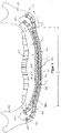
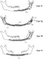
- FIG 1 shows a human lower jaw 113 with a corpus 142 and two ascending branches 112.
- a first bone plate 101 is applied and fastened to the lower jaw 113 .
- the bone plate 101 includes a main portion 109 having a first end 143 and an opposite second end 148 and extending along a centerline M from the first end 143 to the second end 148 .
- the main section 109 also has a first contact surface 141, which cannot be seen here, on which the main section 109 is placed and attached to the body 142 (see Figure 4a ).
- the main section 109 has a plurality of receptacles 108, 108', each with a circular opening 102, 102' for receiving a bone screw 301, not shown here (see Figures 6a and 6b ).
- Two wings 110 arranged next to one another extend both from the first end 143 and from the second end 148 of the main section 109. These each have a second contact surface 144 (not visible here) (see also Figure 4a) for contact and attachment to an outside of one of the ascending branches 112. Furthermore, the wings 110 have receptacles 145, each with a circular opening 146 for receiving a bone screw 301, not shown here (see Figures 6a and 6b ).
- the main section 109 has a first minimum bending stiffness in a cross-sectional plane not shown here with respect to an axis running perpendicular to the first contact surface 141 (and thus also perpendicular to the plane of the drawing) (see FIG. 3b for the representation of a cross-sectional plane of another bone plate).
- Each wing 110 does not point here either
- the respective cross-sectional planes illustrated have a respective second minimum bending stiffness with respect to axes running perpendicularly to the respective second contact surface 144 (and thus also perpendicularly to the plane of the drawing).
- the first minimum bending stiffness is greater than each of the second minimum bending stiffnesses, but smaller than the minimum total bending stiffness of all wings 110 extending from the first end 143 and also smaller than the minimum total bending stiffness of all wings 110 extending from the second end 148.
- the main section 109 has a truss structure. It has struts 104 which run transversely to the center line M.
- the openings 102 are located on a first side of the centerline M, and the openings 102' are located on an opposite side of the centerline M from the first side.
- the receptacles 108, 108' with the circular openings 102, 102' are arranged at the nodes of the framework structure. Alternatively, however, nodal points without screw holes are also conceivable. In the exemplary embodiment shown here, the wings 110 do not have such a framework structure.
- the bone plate 101 In the initial state, in particular in the delivery state, the bone plate 101 can be essentially flat, which facilitates manufacture, transport and storage.
- essentially only the wings 110, but not the main section 109 In order to mold the bone plate 101 to the individual anatomy of a patient, essentially only the wings 110, but not the main section 109, can be bent by suitably selected bending moments within the plane of the plate.
- essentially only the wings 110 in the plane of the plate can be molded to the individual anatomy of a patient, for example to the angle between the corpus 142 and the ascending branch 112.
- the main section 109 can essentially only be deformed by bending out of the plane defined by the contact surface 141 into an anatomical shape in which it can be attached to the lower jaw 113.
- the bone plates are suitably shaped, deformation of the main section 109 within the plane of the plate is not necessary at all in order to be able to mold the bone plate 101 onto the corpus 142 of a large number of human lower jaws 113. Instead, the low deformability of the main section 109 within the plane of the plate has the advantage that the bone plate 101 is stable with respect to forces and bending moments acting in this plane of the plate.
- the two wings 110 are also fixed relative to one another, so that the minimum overall bending stiffness of these wings 110 is relevant in this implanted state. Since this overall flexural rigidity is greater than the first minimum flexural rigidity of the main section 109, the wings 110 can hardly be deformed within the plane of the plate in the implanted state, which also leads to greater stability in this area with respect to forces and bending moments acting in the plane of the plate. If the bone to be treated is a lower jaw, the requirement that the total flexural rigidity is greater than the first flexural rigidity is due to the real force distribution in the lower jaw: near the joint, the load on the bone when chewing/biting is greater than towards the chin.
- the main section 109 is delimited on both sides S 1 , S 2 by a frame structure 105 which has an outer edge 107 which runs essentially in a straight line. This allows Edges are avoided, which could lead to injury to body tissue, for example.
- the main section 109 has a width b 1 of 10 mm and a length l 1 measured along the center line M of 145 mm.
- the wings 110 have a width b 2 of 7 mm.
- the shorter wings 110 shown above have a length l 2 of 19 mm, and the figure 1 longer wings 110 shown below have a length l 2 'of 26 mm.
- each wing 110 has a width b 2 which is at most 80% of the width b 1 of the main section 109 .
- the bone plate consists of a biocompatible implant material, such as titanium and its alloys, implant steel, implantable plastic or implantable ceramic.
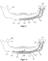
- the Figures 2 and 3a show a human lower jaw 113 with two further bone plates 101 'or 101'.
- Their main sections 109 each have two wings 110 only at a first end 143. Only a single wing 110 is arranged at the opposite second end 148.
- the main section 109 of the in Figure 3a illustrated third bone plate 101" is longer than the main section 109 in FIG figure 2 illustrated second bone plate 101'.
- the in Figure 3a illustrated third bone plate 101 cover a larger area of the corpus 142, as below in connection with Figures 9a to 9i and 10 becomes clear.
- Figure 3b is a cross-sectional view taken along line III-III in FIG Figure 3a shown.
- the cross-sectional plane is perpendicular to the centerline M of the main section 109. However, it is not necessarily the one where the minimum bending stiffness of the main section 109 exists.
- a Cartesian coordinate system is drawn in, whose origin is the common centroid P of the three partial cross-sectional areas A 1 , A 2 and A 3 is formed.
- the x-axis is perpendicular to the landing surface 141 and the y-axis is substantially parallel to the centerline M.
- the x-axis and the z-axis together span the partial cross-sectional areas A 1 , A 2 and A 3 .
- a common coordinate system is used for each of the three integrals, the origin of which lies in the center of gravity of the total area and not the centroids of the partial cross-sectional areas.
- the flexural rigidity results from the product of this axial moment of inertia with the modulus of elasticity of the bone plate 101".
- Figure 4a 10 shows a perspective view of the second bone plate 101' according to FIG figure 2 .
- the main portion 109 has a first abutment 141 for abutment and attachment to the body 142, and the two wings 110 each include a second abutment 144 for abutment and attachment to the ascending branch 112.
- Each of the openings 102, 102' and 146 has a structure shown in detail in accordance with FIG Figure 4b can be seen.
- the Opening 102 is used to hold one in the Figures 6a and 6b illustrated first bone screw 301.
- the opening 102 penetrates the bone plate 101 along a longitudinal axis L from an upper side 202 of the bone plate 101 to an opposite underside 203 of the bone plate 101.
- the opening 102 opens into a first receiving area 204, which is surrounded by a first Inner wall 205 is limited.
- the opening 102 opens into a second receiving area 206, which is delimited by a second inner wall 207.
- Three recesses 208 are formed in the circumferential direction in the first inner wall 205 .
- the distance between the first inner wall 205 increases as a function of the angle of rotation about the longitudinal axis L.
- the first inner wall 205 is spherical in the area of each of the recesses 208.
- the first inner wall 205 can also be configured paraboloidally, ellipsoidally or hyperboloidally, for example.
- three recesses 209 are formed in the second inner wall 207 in the circumferential direction. In each of these three recesses 209, the distance between the second inner wall 207 increases depending on the angle of rotation about the longitudinal axis L.
- the second inner wall 207 is spherical in the area of each of the recesses 209, but could alternatively also be paraboloidal, ellipsoidal or be hyperboloidal.
- the first receiving area 204 also contains a spherical countersink 210 for receiving a connecting element, in particular a screw head, of a bone screw not shown here.
- the first recess 204 has an outlet contour 212, which is used for guiding out a bone screw.
- the two receiving areas 204, 206 are designed for co-rotating blocking. Both recording areas are more accurate 204, 206 designed for a clockwise locking.
- a locking element of a bone screw can therefore be fixed both in the direction of view from the top 202 to the bottom 203 by turning the bone screw clockwise in the first receiving area 204 and in the direction of view from the bottom 203 to the top 202 by turning the bone screw clockwise in the second receiving area 206 will.
- Figure 5a Figure 12 shows a plan view of the second bone plate 101'. As per the sectional view Figure 5b As can be seen, the second receiving area 206 also contains a spherical countersink 211 and an outlet contour 213.
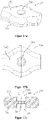
- FIGS. 6a and 6b show a first bone screw 301, which can be used at variable angles in each of the openings 102, 102' and 146.
- This bone screw 301 is identical to that in WO 2004/086990 revealed. It has a screw shank 320 with a thread 321 and a screw head 310 designed as a locking element, which projects outwards beyond the screw shank 320 and the thread 321 .
- the screw head 310 has an engagement contour 311 into which, for example, a screwdriver can be inserted in order to screw the bone screw 301 in or out.
- the screw head 310 is provided with a circumferential outer surface which extends essentially in the direction of a longitudinal axis K of the bone screw 301 and has three clamping surfaces 330 distributed uniformly in the circumferential direction. Viewed in an azimuth plane perpendicular to the longitudinal axis K, the clamping surfaces 330 widen outwards and away from the longitudinal axis K in the shape of a wedge.
- the outer surface is spherical in the area of the clamping surfaces 330 .
- clamping surfaces 330 allow the screw head 310 to be blocked either with the first inner wall 205 or the second inner wall 207, as is shown in detail in WO 2004/086990 is described (which, however, is only one opening having a single receiving area as disclosed herein).
- both the upper side 202 and the lower side 203 can optionally serve as contact surfaces that are placed against the bone.
- the bone plates can therefore be used for left-sided or right-sided defects, as required, without having to do without variable-angle fixation. This significantly reduces the range of bone plates to be kept on hand.
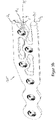
- This in figure 7 shown reconstruction set contains the two in the Figures 2 to 3b illustrated bone plates 101 'and 101 "and a connecting plate 131, which is shown twice in two different views.
- the connecting plate 131 contains a plurality of openings 132 for receiving a fastening element, such as for example one in figure 8 connecting screw 163 shown.
- the connecting screw 163 can penetrate one of the openings 102, 102' or 146 of the bone plates or an opening of another bone plate for connection, and its thread can penetrate a thread located in the connecting plate. This allows a variable lengthening or even the coupling of two plates to adapt to the individual anatomy or the individual bone defect.
- a reconstruction set is also conceivable in which a jaw joint prosthesis can be connected directly to one of the bone plates, ie without an additional carrier element.
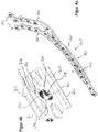
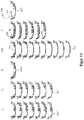
- a first bone screw 340 according to the invention is shown.
- This contains a screw head 341 with an engagement contour 342, a screw shank 343 with a thread 347 and a locking element 345 arranged on an end 344 of the bone screw 340 opposite the screw head 341.
- This locking element 345 contains three clamping surfaces 346 distributed uniformly in the circumferential direction, which are designed as in WO 2004/086990 disclosed.
- the Figures 12a and 12b show a second bone screw 350 according to the invention, which however has no screw head. At a first end 351, it has an engagement contour 352, and at a second end 354 opposite the first end 351, it has a locking element 355 which, like that in FIGS Figures 11a and 11b
- the blocking element 345 shown has three clamping surfaces 356.
- a screw shank 353 with a thread 357 extends between the first end 351 and the second end 354.
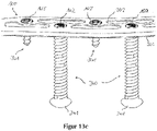
- the Figures 13a to 13c show the bone plate 101' figure 2 with two as in the Figures 11a and 11b illustrated bone screws according to the invention 340 and two as in the Figures 6a and 6b shown bone screws 301.
- Figure 13a are the shorter bone screws 301 according to Figures 6a and 6b inserted from the top 202 of the bone plate 101' towards the bottom 203 and penetrating the openings 102'.
- the bone screws 340 according to Figures 11a and 11b have their ends 344 directed towards the underside 203 but not yet in contact with it.
- Figure 13c Figure 12 includes a perspective view of top 202 of bone plate 101'.
- the bone screws 340 can provide additional stability.
- the shorter bone screws 301 can penetrate through the bone plate 101' and then externally into a mandible, and the longer bone screws 340 can completely penetrate the mandible from the inside out and then engage the bone plate 101'.
- a conceivable indication is the degradation of a bone, which may have occurred, for example, as a result of previous radiation.
- FIGS. 14a and 14b show the same bone plate 101', but in its openings 102, 102' according to FIG Figure 14b four of the shorter bone screws 301 can be used.
- a first bone screw 301 and a second bone screw 301 penetrate the bone plate 101' from the top 202 to the bottom 203, the first bone screw 301 penetrating an opening 102 and the second bone screw 301 penetrating an opening 102'.
- a third bone screw 301 and a fourth bone screw 301 penetrate the bone plate 101' from the bottom 203 to the top 202, the third bone screw 301 penetrating an opening 102 and the fourth bone screw 301 penetrating an opening 102'.
- a first part of the bone plate 101' could be screwed in from the oral cavity in the area of a jaw joint, while a second part of the bone plate 101' in the corpus region could be screwed in from the outside.
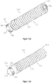
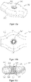
- the Figures 15a to 15c show sections of another bone plate 360, which is shown in Figure 15a in a perspective view, in Figure 15b in a plan view and in Figure 15c in a sectional view along the in Figure 15b drawn section line is shown.
- the bone plate 360 contains an opening 361 which opens into a first receiving area 364 on an upper side 362 of the bone plate 360 and into a second receiving area 366 on an underside 363 .
- Both the first receiving area 364 and the second receiving area 366 contain a cone-shaped internal thread 367 and 368, respectively, which widen in the direction of the upper side 362 and the lower side 363, respectively.
- both internal threads 367, 368 are identical to one another.
- the Figures 16a to 16c show sections of another bone plate 370, which is Figure 16a in a perspective view, in Figure 16b in a plan view and in Figure 16c in a sectional view along the in Figure 16b drawn section line is shown.
- the bone plate 370 contains an opening 371 which opens into a first receiving area 374 on an upper side 372 of the bone plate 370 and into a second receiving area 376 on an underside 373 .
- Both the first receiving area 374 and the second receiving area 376 contain a cone-shaped internal thread 377 and 378, respectively, which widen in the direction of the upper side 372 and the lower side 373, respectively.
- only the opening angles of the two internal threads 377, 378 are identical; however, the first internal thread 377 is higher than the second internal thread 378.
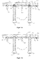
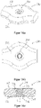
- FIGS 17a to 17c show sections of another bone plate 380, which is shown in Figure 17a in a perspective view, in Figure 17b in a plan view and in Figure 17c in a sectional view along the in Figure 17b drawn section line is shown.
- the bone plate 380 contains an opening 381 which opens into a first receiving area 384 on an upper side 382 of the bone plate 380 and into a second receiving area 386 on an underside 383 .
- Both the first receiving area 384 and the second receiving area 386 are designed in the shape of a circular cylinder, but do not contain any internal threads. Between the two receiving areas 384, 386 there is also a circular-cylindrical intermediate area 389, but its radius is smaller than that of the receiving areas 384, 386.
- Bone plate 390 includes an opening 391 formed at a top surface 392 of bone plate 390 in opens into a first receiving area 394 and opens into a second receiving area 396 on an underside 393 . Both the first receiving area 394 and the second receiving area 396 are cone-shaped and widen in the direction of the upper side 392 or the lower side 393 . Between the two receiving areas 394, 396 there is a circular-cylindrical intermediate area 399, the radius of which is smaller than the smallest radius of the receiving areas 394, 396.
- Bone plates 360, 370, 380, 390 shown can use bone screws with a slotted screw head (such as in CH 669 105 A5 ) or with a spherical screw head (such as in CH 675 531 A5 ) are used.
- a slotted screw head such as in CH 669 105 A5
- a spherical screw head such as in CH 675 531 A5
Priority Applications (3)
| Application Number | Priority Date | Filing Date | Title |
|---|---|---|---|
| EP22207515.2A EP4197466A1 (de) | 2014-12-17 | 2014-12-17 | Knochenplatte, chirurgische sets und rekonstruktionssets |
| EP19203806.5A EP3616636B1 (de) | 2014-12-17 | 2014-12-17 | Knochenplatte und chirurgische sets |
| ES19203806T ES2938683T3 (es) | 2014-12-17 | 2014-12-17 | Placa de osteosíntesis y sets quirúrgicos |
Applications Claiming Priority (3)
| Application Number | Priority Date | Filing Date | Title |
|---|---|---|---|
| EP14816223.3A EP3232962B1 (de) | 2014-12-17 | 2014-12-17 | Knochenplatte, chirurgische sets und rekonstruktionssets |
| PCT/EP2014/078136 WO2016095978A1 (de) | 2014-12-17 | 2014-12-17 | Knochenplatte, chirurgische sets und rekonstruktionssets |
| EP19203806.5A EP3616636B1 (de) | 2014-12-17 | 2014-12-17 | Knochenplatte und chirurgische sets |
Related Parent Applications (1)
| Application Number | Title | Priority Date | Filing Date |
|---|---|---|---|
| EP14816223.3A Division EP3232962B1 (de) | 2014-12-17 | 2014-12-17 | Knochenplatte, chirurgische sets und rekonstruktionssets |
Related Child Applications (1)
| Application Number | Title | Priority Date | Filing Date |
|---|---|---|---|
| EP22207515.2A Division EP4197466A1 (de) | 2014-12-17 | 2014-12-17 | Knochenplatte, chirurgische sets und rekonstruktionssets |
Publications (2)
| Publication Number | Publication Date |
|---|---|
| EP3616636A1 EP3616636A1 (de) | 2020-03-04 |
| EP3616636B1 true EP3616636B1 (de) | 2022-11-16 |
Family
ID=52144684
Family Applications (3)
| Application Number | Title | Priority Date | Filing Date |
|---|---|---|---|
| EP19203806.5A Active EP3616636B1 (de) | 2014-12-17 | 2014-12-17 | Knochenplatte und chirurgische sets |
| EP14816223.3A Active EP3232962B1 (de) | 2014-12-17 | 2014-12-17 | Knochenplatte, chirurgische sets und rekonstruktionssets |
| EP22207515.2A Pending EP4197466A1 (de) | 2014-12-17 | 2014-12-17 | Knochenplatte, chirurgische sets und rekonstruktionssets |
Family Applications After (2)
| Application Number | Title | Priority Date | Filing Date |
|---|---|---|---|
| EP14816223.3A Active EP3232962B1 (de) | 2014-12-17 | 2014-12-17 | Knochenplatte, chirurgische sets und rekonstruktionssets |
| EP22207515.2A Pending EP4197466A1 (de) | 2014-12-17 | 2014-12-17 | Knochenplatte, chirurgische sets und rekonstruktionssets |
Country Status (7)
| Country | Link |
|---|---|
| US (2) | US10828068B2 (pt) |
| EP (3) | EP3616636B1 (pt) |
| JP (1) | JP6605607B2 (pt) |
| AU (2) | AU2014414444B2 (pt) |
| BR (1) | BR112017011949B8 (pt) |
| ES (2) | ES2764215T3 (pt) |
| WO (1) | WO2016095978A1 (pt) |
Families Citing this family (3)
| Publication number | Priority date | Publication date | Assignee | Title |
|---|---|---|---|---|
| US10786289B2 (en) * | 2014-07-16 | 2020-09-29 | The Regents Of The University Of Colorado A Body Corporate | System and methods for positioning of two or more interacting elements |
| DE102015122793A1 (de) * | 2015-12-23 | 2017-06-29 | Karl Leibinger Medizintechnik Gmbh & Co. Kg | Implantat zur Knochenverstärkung mit Bohrvektorvorgabeloch und Umgriffsplatte für Kieferersatz sowie Implantatherstellverfahren |
| US10702319B2 (en) * | 2018-07-09 | 2020-07-07 | Robert G. Hale | Apparatus and method for a transalveolar dental implant |
Citations (1)
| Publication number | Priority date | Publication date | Assignee | Title |
|---|---|---|---|---|
| EP1107699B1 (de) * | 1998-08-25 | 2003-11-05 | Medartis AG | Osteosynthetische fixationsvorrichtung |
Family Cites Families (44)
| Publication number | Priority date | Publication date | Assignee | Title |
|---|---|---|---|---|
| DE3601715A1 (de) * | 1986-01-22 | 1987-07-23 | Heinl Thomas | Chirurgisches instrumentenset zum verbinden von knochenfragmenten |
| US4726808A (en) | 1986-06-30 | 1988-02-23 | Collins Thomas A | Mandibular prosthesis |
| CH669105A5 (de) | 1986-11-25 | 1989-02-28 | Synthes Ag | Interne fixationsvorrichtung fuer die osteosynthese. |
| FR2622431A1 (fr) * | 1987-11-03 | 1989-05-05 | Letournel Emile | Plaque pour l'osteosynthese du calcaneum |
| CH675531A5 (en) | 1988-04-29 | 1990-10-15 | Synthes Ag | Instrument for osteosynthesis with perforated plate - has convex head bone screws fitting in tapering holes in osteosynthesis plate |
| RU2033105C1 (ru) | 1991-06-24 | 1995-04-20 | Александр Сергеевич Артюшкевич | Накостная пластина для лечения переломов нижней челюсти в области симфиза |
| WO1995032674A1 (de) | 1994-06-01 | 1995-12-07 | Synthes Ag, Chur | Gabelplatte |
| WO1999011188A1 (de) | 1997-09-04 | 1999-03-11 | Synthes Ag Chur | Symmetrische knochenplatte |
| US6129728A (en) * | 1998-02-18 | 2000-10-10 | Walter Lorenz Surgical, Inc. | Method and apparatus for mandibular osteosynthesis |
| EP1175181B1 (de) | 1999-05-03 | 2005-01-12 | Medartis AG | Verblockbare knochenplatte |
| DE29909025U1 (de) * | 1999-05-25 | 1999-11-04 | Lipat Consulting Ag Basel | Osteosynthetische Knochenplatte |
| DE20007908U1 (de) | 2000-05-03 | 2000-12-21 | Medartis Ag Basel | Konturierte Knochenplatte |
| US7963966B2 (en) | 2000-06-06 | 2011-06-21 | Cole J Dean | Bone fixation system and method of use |
| US7578825B2 (en) | 2004-04-19 | 2009-08-25 | Acumed Llc | Placement of fasteners into bone |
| US20050090825A1 (en) | 2002-02-15 | 2005-04-28 | Medartis Ag | Bone plate |
| DE20300181U1 (de) | 2003-01-08 | 2003-05-22 | Fischer Barber Andrea Maria | Gitteranordnung für die Osteosynthese |
| WO2004086990A1 (de) * | 2003-04-03 | 2004-10-14 | Medartis Ag | Aufnahme für ein verblockungselement und verblockungselement |
| DE10317871B3 (de) | 2003-04-17 | 2004-11-11 | Stryker Leibinger Gmbh & Co. Kg | Osteosynthese-Vorrichtung |
| US7776076B2 (en) | 2004-05-11 | 2010-08-17 | Synthes Usa, Llc | Bone plate |
| JP3099430U (ja) | 2003-07-24 | 2004-04-08 | 維綱生物科技股▲ふん▼有限公司 | 医療用骨板 |
| US20050124472A1 (en) | 2003-12-04 | 2005-06-09 | John Carlucci | Muscle stretching device and method for using the same |
| US20050245933A1 (en) | 2004-05-03 | 2005-11-03 | Sevrain Lionel C | Multi coaxial screw system |
| DE102005032026B3 (de) | 2005-07-08 | 2006-12-14 | Stryker Leibinger Gmbh & Co. Kg | Osteosyntheseplatte mit schräg zur Plattenebene verlaufenden Durchgangsöffnungen |
| US8246663B2 (en) * | 2006-04-10 | 2012-08-21 | Scott Lovald | Osteosynthesis plate, method of customizing same, and method for installing same |
| ATE513519T1 (de) | 2007-05-03 | 2011-07-15 | Medartis Ag | Fixiervorrichtung, kombination einer fixiervorrichtung mit einem länglichen element, anordnung mit einer solchen kombination sowie osteosyntheseset |
| US8262706B2 (en) | 2007-07-11 | 2012-09-11 | Stryker Trauma Gmbh | Device for creating a bone implant |
| US8821580B2 (en) * | 2007-09-13 | 2014-09-02 | Swiss Ortho, Llc | System for making a bone repair |
| WO2009148762A2 (en) * | 2008-05-09 | 2009-12-10 | Skeletal Dynamics Llc | Formable bone plate, clamping apparatus, osteotomy system and method for reconstructing a bone |
| EP2303191A4 (en) | 2008-06-02 | 2012-12-12 | Skeletal Dynamics Llc | ORTHOPEDIC HYBRID IMPLANT |
| US9107712B2 (en) * | 2008-09-15 | 2015-08-18 | Biomet C.V. | Bone plate system for hand fractures and other small bones |
| AU2009335771B2 (en) | 2008-12-18 | 2015-01-29 | 4-Web, Inc. | Truss implant |
| US9855082B2 (en) | 2009-05-12 | 2018-01-02 | DePuy Synthes Products, Inc. | Readjustable locking plate hole |
| BRPI1014714B1 (pt) | 2009-07-06 | 2020-05-19 | Synthes Gmbh | conjunto de fixação óssea expansível |
| EP2509524B1 (en) | 2009-12-11 | 2014-02-26 | Synthes GmbH | Mandibular fixation plate |
| EP2340777B1 (de) * | 2009-12-30 | 2014-11-05 | Medartis AG | Osteosyntheseplatte zur Versorgung gelenksnaher Frakturen oder Osteotomien |
| US9066733B2 (en) | 2010-04-29 | 2015-06-30 | DePuy Synthes Products, Inc. | Orthognathic implant and methods of use |
| US20120010668A1 (en) | 2010-07-08 | 2012-01-12 | Warsaw Orthopedic, Inc. | Expandable surgical implant |
| DE102010048052B4 (de) | 2010-10-12 | 2015-06-25 | Bernhard Clasbrummel | Nagel-Schrauben-System für eine Osteosynthese |
| TWI452992B (zh) | 2011-10-17 | 2014-09-21 | Taichung Veterans General Hospital Vacrs | Interlocking plate system |
| EP2768412A1 (en) | 2011-10-18 | 2014-08-27 | Biomet Manufacturing Corp. | Compressive distal humerus plating system |
| US10039582B2 (en) * | 2011-12-20 | 2018-08-07 | DePuy Synthes Products, Inc. | Self centering feature for an intramedullary nail |
| US8485820B1 (en) | 2011-12-22 | 2013-07-16 | Mohamed Ikbal Ali | Devices and methods for enhancing bone growth |
| JP6174111B2 (ja) | 2012-03-13 | 2017-08-02 | シンセス・ゲーエムベーハーSynthes GmbH | 動的骨固定要素 |
| DE102014107495A1 (de) | 2014-05-27 | 2015-12-03 | Aesculap Ag | Knochenschraubensystem |
-
2014
- 2014-12-17 EP EP19203806.5A patent/EP3616636B1/de active Active
- 2014-12-17 EP EP14816223.3A patent/EP3232962B1/de active Active
- 2014-12-17 WO PCT/EP2014/078136 patent/WO2016095978A1/de active Application Filing
- 2014-12-17 BR BR112017011949A patent/BR112017011949B8/pt active IP Right Grant
- 2014-12-17 EP EP22207515.2A patent/EP4197466A1/de active Pending
- 2014-12-17 US US15/536,430 patent/US10828068B2/en active Active
- 2014-12-17 AU AU2014414444A patent/AU2014414444B2/en active Active
- 2014-12-17 JP JP2017532957A patent/JP6605607B2/ja active Active
- 2014-12-17 ES ES14816223T patent/ES2764215T3/es active Active
- 2014-12-17 ES ES19203806T patent/ES2938683T3/es active Active
-
2020
- 2020-02-18 AU AU2020201146A patent/AU2020201146B2/en active Active
- 2020-10-09 US US17/067,171 patent/US11839409B2/en active Active
Patent Citations (1)
| Publication number | Priority date | Publication date | Assignee | Title |
|---|---|---|---|---|
| EP1107699B1 (de) * | 1998-08-25 | 2003-11-05 | Medartis AG | Osteosynthetische fixationsvorrichtung |
Also Published As
| Publication number | Publication date |
|---|---|
| AU2020201146A1 (en) | 2020-03-05 |
| EP3232962B1 (de) | 2019-10-23 |
| US10828068B2 (en) | 2020-11-10 |
| JP6605607B2 (ja) | 2019-11-13 |
| BR112017011949B8 (pt) | 2022-05-24 |
| EP3616636A1 (de) | 2020-03-04 |
| BR112017011949B1 (pt) | 2022-05-17 |
| ES2938683T3 (es) | 2023-04-13 |
| ES2764215T3 (es) | 2020-06-02 |
| WO2016095978A1 (de) | 2016-06-23 |
| EP4197466A1 (de) | 2023-06-21 |
| AU2014414444B2 (en) | 2019-12-05 |
| US20210030442A1 (en) | 2021-02-04 |
| BR112017011949A2 (pt) | 2017-12-26 |
| EP3232962A1 (de) | 2017-10-25 |
| US11839409B2 (en) | 2023-12-12 |
| AU2020201146B2 (en) | 2022-05-12 |
| AU2014414444A1 (en) | 2017-07-06 |
| JP2017538520A (ja) | 2017-12-28 |
| US20170348023A1 (en) | 2017-12-07 |
Similar Documents
| Publication | Publication Date | Title |
|---|---|---|
| EP0347874B1 (de) | Vorrichtung zum Verbinden eines, insbesondere im Bereich des Oberschenkelhalses, gebrochenen Knochens | |
| EP2030596B1 (de) | Implantat zur Behandlung von Knochen. | |
| EP1901671B1 (de) | Osteosyntheseplatte mit schräg zur plattenebene verlaufenden durchgangsöffnungen | |
| EP1861031B1 (de) | Knochenplatte | |
| EP1691701B1 (de) | Osteosyntheseplatten-Set | |
| DE69832389T2 (de) | System für die vorder-verplattung der halswirbelsäule | |
| DE69530972T2 (de) | Für die dorsale, lumare wirbelsäulenosteosynthese geeignetes instrumentarium zur korrektur einer kyphose von vorn | |
| EP1211993A1 (de) | Fixationssystem für knochen | |
| EP1684651A1 (de) | Platte zum stabilisieren distaler radiusfrakturen | |
| EP1927322B1 (de) | Vorrichtung zum Positionieren von Röhrenknochen | |
| DE3839859A1 (de) | Knochenplatte | |
| DE10125092A1 (de) | Osteoxyntheseplatte (Titan) zur inneren Schienung von Knochenbrüchen am körperfernen Ende der menschlichen Speiche zur Anlage an der Streckseite des Knochens - genannt: Y-Platte | |
| EP3616636B1 (de) | Knochenplatte und chirurgische sets | |
| DE102020116610A1 (de) | Frakturfixierungssystem und verfahren | |
| EP2923676A1 (de) | Augenhöhlenabdeckgitter mit außerkonturfolgenden länglichen Ausnehmungen | |
| EP1679044B1 (de) | Set zur Erstellung eines Osteosyntheseimplantates | |
| DE202014004378U1 (de) | Implantat mit Einbring- und Entfernungsinstrumenten zur Distraktionsarthrodese des ISG | |
| DE10118985A1 (de) | Hüftgelenkpfannen-System | |
| EP3834778A1 (de) | Implantat zur behandlung von knochen | |
| DE202009018865U1 (de) | Block aus Knochen - Knochenersatzmaterial | |
| EP2934355B1 (de) | Verriegelbarer marknagel mit führungsdrahtdurchlässen | |
| DE102015120847A1 (de) | Implantatsystem | |
| DE102021111653A1 (de) | Medizinisches Implantat zur Osteosynthese | |
| EP4013322A1 (de) | Platte zur temporären überbrückung von fragmenten einer fraktur | |
| EP3875049A1 (de) | Kit, platte und insert zur versorgung einer clavicula |
Legal Events
| Date | Code | Title | Description |
|---|---|---|---|
| PUAI | Public reference made under article 153(3) epc to a published international application that has entered the european phase |
Free format text: ORIGINAL CODE: 0009012 |
|
| STAA | Information on the status of an ep patent application or granted ep patent |
Free format text: STATUS: THE APPLICATION HAS BEEN PUBLISHED |
|
| AC | Divisional application: reference to earlier application |
Ref document number: 3232962 Country of ref document: EP Kind code of ref document: P |
|
| AK | Designated contracting states |
Kind code of ref document: A1 Designated state(s): AL AT BE BG CH CY CZ DE DK EE ES FI FR GB GR HR HU IE IS IT LI LT LU LV MC MK MT NL NO PL PT RO RS SE SI SK SM TR |
|
| STAA | Information on the status of an ep patent application or granted ep patent |
Free format text: STATUS: REQUEST FOR EXAMINATION WAS MADE |
|
| 17P | Request for examination filed |
Effective date: 20200904 |
|
| RBV | Designated contracting states (corrected) |
Designated state(s): AL AT BE BG CH CY CZ DE DK EE ES FI FR GB GR HR HU IE IS IT LI LT LU LV MC MK MT NL NO PL PT RO RS SE SI SK SM TR |
|
| RIC1 | Information provided on ipc code assigned before grant |
Ipc: A61F 2/28 20060101ALI20220209BHEP Ipc: A61B 17/68 20060101ALI20220209BHEP Ipc: A61B 17/86 20060101ALI20220209BHEP Ipc: A61B 17/80 20060101AFI20220209BHEP |
|
| GRAP | Despatch of communication of intention to grant a patent |
Free format text: ORIGINAL CODE: EPIDOSNIGR1 |
|
| STAA | Information on the status of an ep patent application or granted ep patent |
Free format text: STATUS: GRANT OF PATENT IS INTENDED |
|
| GRAJ | Information related to disapproval of communication of intention to grant by the applicant or resumption of examination proceedings by the epo deleted |
Free format text: ORIGINAL CODE: EPIDOSDIGR1 |
|
| INTG | Intention to grant announced |
Effective date: 20220318 |
|
| STAA | Information on the status of an ep patent application or granted ep patent |
Free format text: STATUS: REQUEST FOR EXAMINATION WAS MADE |
|
| INTC | Intention to grant announced (deleted) | ||
| GRAP | Despatch of communication of intention to grant a patent |
Free format text: ORIGINAL CODE: EPIDOSNIGR1 |
|
| STAA | Information on the status of an ep patent application or granted ep patent |
Free format text: STATUS: GRANT OF PATENT IS INTENDED |
|
| INTG | Intention to grant announced |
Effective date: 20220628 |
|
| GRAS | Grant fee paid |
Free format text: ORIGINAL CODE: EPIDOSNIGR3 |
|
| GRAA | (expected) grant |
Free format text: ORIGINAL CODE: 0009210 |
|
| STAA | Information on the status of an ep patent application or granted ep patent |
Free format text: STATUS: THE PATENT HAS BEEN GRANTED |
|
| AC | Divisional application: reference to earlier application |
Ref document number: 3232962 Country of ref document: EP Kind code of ref document: P |
|
| AK | Designated contracting states |
Kind code of ref document: B1 Designated state(s): AL AT BE BG CH CY CZ DE DK EE ES FI FR GB GR HR HU IE IS IT LI LT LU LV MC MK MT NL NO PL PT RO RS SE SI SK SM TR |
|
| REG | Reference to a national code |
Ref country code: GB Ref legal event code: FG4D Free format text: NOT ENGLISH |
|
| REG | Reference to a national code |
Ref country code: CH Ref legal event code: EP |
|
| REG | Reference to a national code |
Ref country code: DE Ref legal event code: R096 Ref document number: 502014016438 Country of ref document: DE |
|
| REG | Reference to a national code |
Ref country code: IE Ref legal event code: FG4D Free format text: LANGUAGE OF EP DOCUMENT: GERMAN |
|
| REG | Reference to a national code |
Ref country code: AT Ref legal event code: REF Ref document number: 1531290 Country of ref document: AT Kind code of ref document: T Effective date: 20221215 |
|
| REG | Reference to a national code |
Ref country code: LT Ref legal event code: MG9D |
|
| REG | Reference to a national code |
Ref country code: NL Ref legal event code: MP Effective date: 20221116 |
|
| REG | Reference to a national code |
Ref country code: ES Ref legal event code: FG2A Ref document number: 2938683 Country of ref document: ES Kind code of ref document: T3 Effective date: 20230413 |
|
| PG25 | Lapsed in a contracting state [announced via postgrant information from national office to epo] |
Ref country code: SE Free format text: LAPSE BECAUSE OF FAILURE TO SUBMIT A TRANSLATION OF THE DESCRIPTION OR TO PAY THE FEE WITHIN THE PRESCRIBED TIME-LIMIT Effective date: 20221116 Ref country code: PT Free format text: LAPSE BECAUSE OF FAILURE TO SUBMIT A TRANSLATION OF THE DESCRIPTION OR TO PAY THE FEE WITHIN THE PRESCRIBED TIME-LIMIT Effective date: 20230316 Ref country code: NO Free format text: LAPSE BECAUSE OF FAILURE TO SUBMIT A TRANSLATION OF THE DESCRIPTION OR TO PAY THE FEE WITHIN THE PRESCRIBED TIME-LIMIT Effective date: 20230216 Ref country code: LT Free format text: LAPSE BECAUSE OF FAILURE TO SUBMIT A TRANSLATION OF THE DESCRIPTION OR TO PAY THE FEE WITHIN THE PRESCRIBED TIME-LIMIT Effective date: 20221116 Ref country code: FI Free format text: LAPSE BECAUSE OF FAILURE TO SUBMIT A TRANSLATION OF THE DESCRIPTION OR TO PAY THE FEE WITHIN THE PRESCRIBED TIME-LIMIT Effective date: 20221116 |
|
| PGFP | Annual fee paid to national office [announced via postgrant information from national office to epo] |
Ref country code: ES Payment date: 20230112 Year of fee payment: 9 Ref country code: CH Payment date: 20230304 Year of fee payment: 9 |
|
| PG25 | Lapsed in a contracting state [announced via postgrant information from national office to epo] |
Ref country code: RS Free format text: LAPSE BECAUSE OF FAILURE TO SUBMIT A TRANSLATION OF THE DESCRIPTION OR TO PAY THE FEE WITHIN THE PRESCRIBED TIME-LIMIT Effective date: 20221116 Ref country code: PL Free format text: LAPSE BECAUSE OF FAILURE TO SUBMIT A TRANSLATION OF THE DESCRIPTION OR TO PAY THE FEE WITHIN THE PRESCRIBED TIME-LIMIT Effective date: 20221116 Ref country code: LV Free format text: LAPSE BECAUSE OF FAILURE TO SUBMIT A TRANSLATION OF THE DESCRIPTION OR TO PAY THE FEE WITHIN THE PRESCRIBED TIME-LIMIT Effective date: 20221116 Ref country code: IS Free format text: LAPSE BECAUSE OF FAILURE TO SUBMIT A TRANSLATION OF THE DESCRIPTION OR TO PAY THE FEE WITHIN THE PRESCRIBED TIME-LIMIT Effective date: 20230316 Ref country code: HR Free format text: LAPSE BECAUSE OF FAILURE TO SUBMIT A TRANSLATION OF THE DESCRIPTION OR TO PAY THE FEE WITHIN THE PRESCRIBED TIME-LIMIT Effective date: 20221116 Ref country code: GR Free format text: LAPSE BECAUSE OF FAILURE TO SUBMIT A TRANSLATION OF THE DESCRIPTION OR TO PAY THE FEE WITHIN THE PRESCRIBED TIME-LIMIT Effective date: 20230217 |
|
| PG25 | Lapsed in a contracting state [announced via postgrant information from national office to epo] |
Ref country code: NL Free format text: LAPSE BECAUSE OF FAILURE TO SUBMIT A TRANSLATION OF THE DESCRIPTION OR TO PAY THE FEE WITHIN THE PRESCRIBED TIME-LIMIT Effective date: 20221116 |
|
| PG25 | Lapsed in a contracting state [announced via postgrant information from national office to epo] |
Ref country code: SM Free format text: LAPSE BECAUSE OF FAILURE TO SUBMIT A TRANSLATION OF THE DESCRIPTION OR TO PAY THE FEE WITHIN THE PRESCRIBED TIME-LIMIT Effective date: 20221116 Ref country code: RO Free format text: LAPSE BECAUSE OF FAILURE TO SUBMIT A TRANSLATION OF THE DESCRIPTION OR TO PAY THE FEE WITHIN THE PRESCRIBED TIME-LIMIT Effective date: 20221116 Ref country code: EE Free format text: LAPSE BECAUSE OF FAILURE TO SUBMIT A TRANSLATION OF THE DESCRIPTION OR TO PAY THE FEE WITHIN THE PRESCRIBED TIME-LIMIT Effective date: 20221116 Ref country code: DK Free format text: LAPSE BECAUSE OF FAILURE TO SUBMIT A TRANSLATION OF THE DESCRIPTION OR TO PAY THE FEE WITHIN THE PRESCRIBED TIME-LIMIT Effective date: 20221116 Ref country code: CZ Free format text: LAPSE BECAUSE OF FAILURE TO SUBMIT A TRANSLATION OF THE DESCRIPTION OR TO PAY THE FEE WITHIN THE PRESCRIBED TIME-LIMIT Effective date: 20221116 |
|
| REG | Reference to a national code |
Ref country code: DE Ref legal event code: R097 Ref document number: 502014016438 Country of ref document: DE |
|
| REG | Reference to a national code |
Ref country code: BE Ref legal event code: MM Effective date: 20221231 |
|
| PG25 | Lapsed in a contracting state [announced via postgrant information from national office to epo] |
Ref country code: SK Free format text: LAPSE BECAUSE OF FAILURE TO SUBMIT A TRANSLATION OF THE DESCRIPTION OR TO PAY THE FEE WITHIN THE PRESCRIBED TIME-LIMIT Effective date: 20221116 Ref country code: LU Free format text: LAPSE BECAUSE OF NON-PAYMENT OF DUE FEES Effective date: 20221217 Ref country code: AL Free format text: LAPSE BECAUSE OF FAILURE TO SUBMIT A TRANSLATION OF THE DESCRIPTION OR TO PAY THE FEE WITHIN THE PRESCRIBED TIME-LIMIT Effective date: 20221116 |
|
| PLBE | No opposition filed within time limit |
Free format text: ORIGINAL CODE: 0009261 |
|
| STAA | Information on the status of an ep patent application or granted ep patent |
Free format text: STATUS: NO OPPOSITION FILED WITHIN TIME LIMIT |
|
| 26N | No opposition filed |
Effective date: 20230817 |
|
| PG25 | Lapsed in a contracting state [announced via postgrant information from national office to epo] |
Ref country code: IE Free format text: LAPSE BECAUSE OF NON-PAYMENT OF DUE FEES Effective date: 20221217 |
|
| PG25 | Lapsed in a contracting state [announced via postgrant information from national office to epo] |
Ref country code: SI Free format text: LAPSE BECAUSE OF FAILURE TO SUBMIT A TRANSLATION OF THE DESCRIPTION OR TO PAY THE FEE WITHIN THE PRESCRIBED TIME-LIMIT Effective date: 20221116 Ref country code: BE Free format text: LAPSE BECAUSE OF NON-PAYMENT OF DUE FEES Effective date: 20221231 |
|
| PGFP | Annual fee paid to national office [announced via postgrant information from national office to epo] |
Ref country code: GB Payment date: 20231102 Year of fee payment: 10 |
|
| PGFP | Annual fee paid to national office [announced via postgrant information from national office to epo] |
Ref country code: IT Payment date: 20231110 Year of fee payment: 10 Ref country code: FR Payment date: 20231108 Year of fee payment: 10 Ref country code: DE Payment date: 20231031 Year of fee payment: 10 Ref country code: AT Payment date: 20231127 Year of fee payment: 10 |
|
| PG25 | Lapsed in a contracting state [announced via postgrant information from national office to epo] |
Ref country code: HU Free format text: LAPSE BECAUSE OF FAILURE TO SUBMIT A TRANSLATION OF THE DESCRIPTION OR TO PAY THE FEE WITHIN THE PRESCRIBED TIME-LIMIT; INVALID AB INITIO Effective date: 20141217 |
|
| PGFP | Annual fee paid to national office [announced via postgrant information from national office to epo] |
Ref country code: ES Payment date: 20240112 Year of fee payment: 10 |