EP3616578A1 - Elektrischer grill mit zwei einen grillraum aufspannenden grillplatten - Google Patents
Elektrischer grill mit zwei einen grillraum aufspannenden grillplatten Download PDFInfo
- Publication number
- EP3616578A1 EP3616578A1 EP18191930.9A EP18191930A EP3616578A1 EP 3616578 A1 EP3616578 A1 EP 3616578A1 EP 18191930 A EP18191930 A EP 18191930A EP 3616578 A1 EP3616578 A1 EP 3616578A1
- Authority
- EP
- European Patent Office
- Prior art keywords
- plate
- grill
- segment
- segments
- base
- Prior art date
- Legal status (The legal status is an assumption and is not a legal conclusion. Google has not performed a legal analysis and makes no representation as to the accuracy of the status listed.)
- Granted
Links
Images



Classifications
-
- A—HUMAN NECESSITIES
- A47—FURNITURE; DOMESTIC ARTICLES OR APPLIANCES; COFFEE MILLS; SPICE MILLS; SUCTION CLEANERS IN GENERAL
- A47J—KITCHEN EQUIPMENT; COFFEE MILLS; SPICE MILLS; APPARATUS FOR MAKING BEVERAGES
- A47J37/00—Baking; Roasting; Grilling; Frying
- A47J37/06—Roasters; Grills; Sandwich grills
- A47J37/0611—Roasters; Grills; Sandwich grills the food being cooked between two heating plates, e.g. waffle-irons
-
- A—HUMAN NECESSITIES
- A47—FURNITURE; DOMESTIC ARTICLES OR APPLIANCES; COFFEE MILLS; SPICE MILLS; SUCTION CLEANERS IN GENERAL
- A47J—KITCHEN EQUIPMENT; COFFEE MILLS; SPICE MILLS; APPARATUS FOR MAKING BEVERAGES
- A47J27/00—Cooking-vessels
- A47J27/002—Construction of cooking-vessels; Methods or processes of manufacturing specially adapted for cooking-vessels
-
- A—HUMAN NECESSITIES
- A47—FURNITURE; DOMESTIC ARTICLES OR APPLIANCES; COFFEE MILLS; SPICE MILLS; SUCTION CLEANERS IN GENERAL
- A47J—KITCHEN EQUIPMENT; COFFEE MILLS; SPICE MILLS; APPARATUS FOR MAKING BEVERAGES
- A47J27/00—Cooking-vessels
- A47J27/004—Cooking-vessels with integral electrical heating means
-
- A—HUMAN NECESSITIES
- A47—FURNITURE; DOMESTIC ARTICLES OR APPLIANCES; COFFEE MILLS; SPICE MILLS; SUCTION CLEANERS IN GENERAL
- A47J—KITCHEN EQUIPMENT; COFFEE MILLS; SPICE MILLS; APPARATUS FOR MAKING BEVERAGES
- A47J37/00—Baking; Roasting; Grilling; Frying
- A47J37/06—Roasters; Grills; Sandwich grills
- A47J37/0611—Roasters; Grills; Sandwich grills the food being cooked between two heating plates, e.g. waffle-irons
- A47J2037/0617—Roasters; Grills; Sandwich grills the food being cooked between two heating plates, e.g. waffle-irons with means to adjust the distance between heating plates
Definitions
- the invention relates to an electric grill with two facing each other across their large plate surfaces, together spanning a grill space, the grill having a first grill plate for supporting food and a second grill plate displaceable relative to the first grill plate, and wherein each grill plate has one Grill plate-holding plate base is assigned.
- Electric grills of the aforementioned type are known in the prior art. These are often referred to as contact grills because the food to be grilled is contacted and cooked on two opposite sides by the grilling plates.
- one of the two grill plates preferably the upper grill plate in relation to a normal operating state, can be displaced relative to the other grill plate, as is also known, for example, from sandwich toasters, waffle irons and the like.
- the US design US D697360 S discloses, for example, an electric grill which has two opposing grill plates, each of which is supported by a plate base.
- the two plate bases can be displaced relative to one another via a hinge.
- a disadvantage of grills of this type is that when using differently high grilled food within the grilling space, there is a different cooking result, for example in such a way that a first grilled food is already cooked through while a second grilled food is still semi-raw. Furthermore, it can if the upper grill plate is pressed on too strongly, for example to compensate for a height difference between several items of grill food placed at the same time, the higher items to be cooked are deformed, which can also impair the cooking result. Pressing it on can also cause the food to be stuck to the grill plates.
- At least one grill plate has at least one plate segment which is displaceably held on the plate base and which, depending on the size and / or shape of a item of food introduced into the grill space, can be automatically displaced relative to the plate base holding this plate segment.
- the height of at least a portion of a grill plate can now be adapted to the height of a food to be cooked.
- a grill plate it is possible, for example, for a grill plate to have a plate segment which is fixed relative to the plate base and a plate segment which is displaceably held on the plate base.
- a grill plate formed by a single plate segment can also be displaced overall relative to the plate base, so that the height of the plate segment can be adjusted both when a relatively thin piece of food and a thicker piece of food are placed on the grill plate, that the grill room is always optimally closed.
- a first plate segment can be displaced relative to a second plate segment advantageously achieved that several items to be cooked in the grill space are held equally flush and with preferably homogeneously acting pressure of the grill plate.
- the plate base is pot-shaped, the plate segment being at least partially displaceable into the plate base.
- Pot-shaped are understood to mean shapes that openly delimit three-dimensional spaces on one side.
- a partial area of the grill plate can protrude into the plate base and a further partial area may protrude beyond an opening level of the grill plate base, namely in the direction of the respectively opposite grill plate or plate base.
- the plate base can preferably serve to guide one or more displaceable plate segments.
- an inner edge region of the plate base provides guides for the displacement movement of a plate segment.
- one plate segment or several plate segments protrude in an open position of the grill space over an edge of the pot-shaped grill plate base and by the closing process, i.e. bringing the opposite plate bases together into the assigned plate base. This can be caused either by contact between the opposing grill plates or by one or more plate segments resting on a grill item.
- the grill space is preferably closed by the grill plate bases and / or grill plates lying against one another in such a way that liquids escaping from the food to be grilled can be collected and discharged in a targeted manner, and an optimum temperature can be provided for the cooking process.
- the grill plate can be displaced several relative to one another and relative to the respectively assigned plate base Has plate segments.
- This configuration is particularly advantageous since several areas of a grill plate can be adapted to the thickness of a food to be grilled. It is therefore also possible to optimally prepare more than two items of grill with different heights in the electric grill, whereby each plate segment can be automatically set to an optimal plate height independently of neighboring plate segments so that the opposite plate segments optimally fit against the food to be placed in between .
- the two opposing grill plates can have displaceable plate segments.
- only the upper grill plate of the electric grill can be designed in such a segmented manner that the height of the grill space, ie the inside opening height, can be varied over a part or the entire area.
- the lower grill plate can also be segmented, but as previously explained, this is not absolutely necessary.
- the opposite plate segments In a closed state of the grill space, the opposite plate segments preferably lie in a frame of the plate base, so that the electric grill can be opened with only a single movement even when the grill plate is segmented.
- a reset element is assigned to the plate segment, which resiliently supports the plate segment on the plate base.
- a spring element can be assigned to each plate segment, which can be tensioned by an applied force. If, for example, there is a food to be grilled between the grilling plates that prevents a defined closed position of the grilling area, or if it protrudes above the levels of other grilling goods, the plate segment is displaced against the restoring force of the spring element until the attacking force diminishes because the overhang of the food in question is eliminated.
- the spring elements can be, for example, spiral springs, leaf springs or similar spring elements.
- the plate segment it is also possible to mount the plate segment on a body made of a resilient material or to form the plate segment itself from a resilient material.
- the elastic mounting of the plate segments i.e. the application of a pretensioning force to the plate segments, ensures that the plate segments are shifted back to an upstream starting position when no more force is applied to the plate segments, i.e. the grill space is open and / or no items to be grilled on the respective one Plate segment abuts and / or the food to be grilled has the same thickness, so that when the grill space is closed, the grill plates rest on the food at an equal height level.
- a plate segment of the second grill plate can be displaced relative to the assigned plate base due to gravity acting on the plate segment.
- the second, ie upper, grill plate can thus alternatively or additionally have a resetting of the plate segments by a spring element, for example also plate segments, which are mounted on the plate base in such a way that they fall down due to gravity when the grill plate is oriented essentially horizontally is, ie the plate segments inside the plate base point vertically downwards.
- an early horizontal position of the upper grill plate can be achieved by a hinge solution between the two plate bases, which not only connects the plate bases to one another via a single axis of rotation, but has a lever with two different axes of rotation, so that the upper one Grill plate can be aligned early or always parallel to the lower plate base regardless of a current position during a closing process.
- a locking mechanism is also advantageous compared to a connection with only a single axis of rotation. because the food to be grilled in the grilling space is not first squeezed together on one side, ie from the hinge side. Rather, the pressure of the upper grill plate can be applied homogeneously to the food to be grilled.
- a plate segment provide a contact surface for grilled food, the surface area of which has an amount of 1 mm 2 to 1000 cm 2 , in particular 20 mm 2 to 200 cm 2 .
- the grill plate can thus have a multiplicity of needle-shaped plate segments which lie next to one another in the manner of a nail board and press against the food to be grilled.
- the grill plate can also have plate segments which are suitable for completely grilling food of the usual area, for example pieces of meat, vegetables and the like, completely and without the involvement of adjacent plate segments.
- the grill plate can be designed in such a way that the grill plate adapts to the surface contour of a grill item by means of a plurality of plate segments, so that the area of the respective grill plate can be optimally used for placing grill items.
- the plate segments of a grill plate it is also possible for the plate segments of a grill plate to have different sizes, so that there can be surface areas which have larger or smaller plate segments than other surface areas.
- a portion of the grill plate can be used for placing large items to be grilled, while other plate segments are advantageous for placing smaller items to be grilled.
- the specified area sizes for the plate segments are suggested here as preferred, an amount of 1 mm 2 denoting an area size as is customary in the case of needle tips, so that a contour of a grill item can be shaped particularly precisely.
- the stated area sizes of up to approx. 1000 cm 2 indicate larger sub-areas of a grill plate, which are designed as a single plate segment.
- the grill plate can, for example, also be displaceable as a whole, ie as a single plate segment, relative to the assigned plate base.
- the grill plate can preferably be inserted as a whole into a pot-shaped plate base in order to enable the grill space to be closed flush.
- Area sizes of a plate segment of between 20 mm 2 and 200 cm 2 are preferred, which corresponds approximately to the area sizes of conventional grilled goods such as pieces of meat, vegetables or the like.
- a grill plate has one plate segment to one thousand plate segments.
- the grill plate can have two to one hundred plate segments, particularly preferably two to ten plate segments.
- the number of plate segments and their size are to be coordinated with one another, wherein, as previously explained, embodiments are possible in which different surface areas of a grill plate have different size and different number of plate segments.
- a grill plate has at least two plate segments, each of the two plate segments being assigned its own heating device, the heating devices of the plate segments being controllable independently of one another with respect to an operating status and / or a heating output and / or a heating duration.
- the temperature of a plate segment can be set individually and independently of the temperature of other plate segments.
- each plate segment or a group of several plate segments can be assigned a heating element which can be energized individually. In this way, different heating outputs and / or different temperature profiles and thus different cooking points can be different Cooking items are taken into account.
- both the plate segments of the first grill plate and the plate segments of the second grill plate can be heated independently of one another.
- the heating device of a plate segment can be switched manually by a user, for example by switching on certain surface areas of the grill plate and leaving others that are not required due to the quantity and size of the food to be grill switched off.
- a heating device can also be controlled automatically, for example by a contact sensor and / or a weighing device, which measure or estimate the presence and / or a weight and / or a volume and / or a size of the food.
- a plate segment be assigned a sensor for detecting a displacement or a state of displacement of the plate segment or for detecting the presence of food to be grilled on a contact surface of the plate segment.
- the sensor can be designed as a contact sensor which, when a contact is detected, concludes that grilled food is present on the respective plate segment.
- the sensor can also relocate, i.e. detect a changing height of the plate segment relative to a plate base or a displacement movement by, for example, an acceleration sensor, a changing resistance or the like.
- the electric grill has a control device which is set up to control a heating device assigned to a plate segment as a function of a detection result of the sensor.
- the control device switches the heating device which is assigned to one or more plate segments currently required.
- plate segments on which no food is currently placed remain switched off. This reduces the power consumption for the operation of the electric grill.
- the control device can also determine the height of an item of food to be grilled by, for example, determining a distance between opposite plate segments of the grill area.
- control device for setting the heating power or setting an expected heating duration can also take into account information about the type of food to be cooked, its cooking point and the like, so that different food items reach an optimal cooking point at the same time and can thus be served at the same time. If necessary, a user of the control device can transmit information about the type of food to be grilled and / or its weight or the like. Furthermore, the control device can also control a keep-warm function or a wait mode, which is switched when a food to be cooked is finished. This means, for example, that food can be kept warm until other dishes are ready.
- one of the grill plates protrudes with respect to a closed state of the grill area with an edge area over the other grill plate and / or the plate base, so that liquid present in the grill room can flow out.
- the first, ie lower grill plate protrudes over the upper second grill plate.
- the protruding grill plate serves for an optimal drainage of liquids from the grill room.
- the protrusion of one of the grill plates creates a gap between them.
- a collecting container can be assigned to the gap, in which the liquid is transferred accordingly.
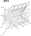
- the in Fig. 1 Grill 1 shown has two opposing grill plates 3, 4. Each of the grill plates 3, 4 is held in a plate base 7, 8, the plate bases 7, 8 being displaceable relative to one another by a mechanism with a hinge 27.
- the hinge 27 has a lever 28 which engages in a guide 29 held on an opposite grill plate 4.
- a guide element 30 of the grill plate 4 also engages in this guide 29.
- the hinge mechanism enables the upper grill plate 4 to move relative to two different axes of rotation, so that the upper grill plate 4 can not only be pivoted relative to the lower grill plate 3, but can also be displaced linearly.
- the two opposite grill plates 3, 4 span between them a grill room 2, into which food 5, 6 is introduced. Here there are two items 5, 6 to be grilled within the grilling space 2, a first item 5 having a different height than a second item 6.
- the grill plates 3, 4 have a plurality of plate segments 9 to 16, the lower grill plate 3 having four plate segments 9 to 12, and the upper grill plate 4 also having four plate segments 13 to 16.
- the plate segments 9 to 12 of the lower grill plate 3 are fixed relative to the assigned plate base 7, while the plate segments 13 to 16 of the upper one Grill plate 4 can be displaced relative to the plate base 8, namely into the plate base 8, which here corresponds, for example, to a displacement movement orthogonal to the plate plane of the plate base 8.
- the upper grill plate 4 can be displaced relative to the lower grill plate 3 by a user engaging a handle 26 formed on the upper grill plate 4 and shifting the upper grill plate 4 to a desired position.
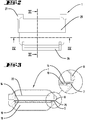
- Fig. 2 shows a top view of the in Fig. 1 Grill 1 shown. It can be seen that the handle 26 protrudes beyond the contour of the grill 1, so that when the handle 26 is gripped the user cannot come into contact with, for example, the upper grill plate 4 and even when the grill space 2 is opened, none Suffering from heat.
- Fig. 3 shows a sectional view of the grill 1 according to the in Fig. 2 designated cutting line III.
- the grill 1 is cut in a vertical plane which intersects the opposite plate segments 10 and 14 of the lower and upper grill plates 3, 4.
- the plate base 8 of the upper grill plate 4 and thus also the plate segment 14 of the upper grill plate 4 is longer than the lower plate base 7 or the lower plate segment 10.
- an edge region 25 of the upper plate segment 14 projects over the lower plate base 7, so that Liquid present in the grill room 2, which is caused by the items 5, 6 contained therein, can flow out of the grill room 2 or be discharged.
- a liquid collecting device can be provided, for example a container, which is placed next to the lower plate base 7.
- Fig. 4 shows a section through the grill 1 according to the in Fig. 2 Line IV shown.
- the grill room 2 is with the two different heights Barbecue items 5, 6 are fitted, with a first item 5 being grilled between the plate segments 9 and 13 of the lower or upper grill plate 3, 4, and a second, thicker item 6 being grilled between the plate segments 11 and 15 of the lower or upper grill plate 3, 4 lies.
- the other plate segments 10, 12, 14, 16 have no food to be grilled.
- a separate heating device 17 to 24 is assigned to each of the plate segments 9 to 16.
- Each of the heaters 17 to 24 can be switched independently of the other heaters 17 to 24.
- the heating devices 17 to 24 are designed, for example, as heating resistors.
- the grill 1 has a control device which is set up to switch the heating devices 17 to 24.
- the plate segments 13 and 15 of the upper grill plate 4 are in Fig. 4 corresponding to the thicknesses of the grilled items 5, 6 shifted.
- the plate base 8 assigned to the plate segments 13 to 16 of the upper grill plate 4 is essentially pot-shaped, so that the plate segments 13 to 16 can be displaced into the upper plate base 8.
- the plate segments 9 to 12 of the lower grill plate 3, on the other hand, are arranged in a stationary manner on the lower plate base 7 and do not shift when they come into contact with the respective grill items 5, 6.
- the distance between the opposite plate segments 9 and 13 corresponds to the height of the grill item 5.
- the distance the opposite plate segments 11 and 15 corresponds to the height of the grilled food 6 in between.
- the upper plate segments 13 to 16 are, for example, slidably mounted on the plate base 8, so that when the plate segments 13 to 16 come into contact with the grilled food 5, 6, there is a relative shift in height comes to the plate base 8.
- the upper plate segments 13, 16 can preferably be assigned a sensor system (not shown here) which detects the presence of a food to be grilled 5, 6 and controls the heating devices 17, 19, 21, 23 assigned to the respective plate segments 9, 11, 13, 15.
- a contact sensor assigned to the plate segments 9, 11, 13, 15 can recognize that a force is exerted on the plate segments 9, 11, 13, 15.
- the control device then closes that on the plate segments 9 and 13 and 11 and 15 a food 5, 6 rests and switches on the heating devices 17, 19, 21, 23 assigned to the plate segments 9, 11, 13, 15.
- a further sensor system for example a weighing device assigned to the lower plate segments 9 to 12, to measure the weight of the food 5, 6 and accordingly to control a temperature and / or heating duration or other parameters of the cooking process.
- Fig. 5 shows a schematic diagram of the segmented grill plates 3, 4, wherein the height levels of the displaced upper plate segments 13, 15 can be seen.
- Fig. 6 shows a three-dimensional sectional view of the grill 1, which further illustrates the structure of the grill 1.
- the different height levels of the plate segments 9 to 16 of the two grill plates 3, 4 and the heating devices 17 to 24 assigned to the plate segments 9 to 16 can be seen.
- one heating device 17 to 24 has several Plate segments 9 to 16 heats simultaneously, or that several heating devices 17 to 24 heat a specific plate segment 9 to 16.
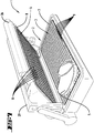
- the Figures 7 to 11 show a second grill 1 according to the invention, in which both grill plates 3, 4 have a very large number of plate segments 9 and 13, respectively.
- the plate segments 9, 13 are here compared to the plate segments 9 to 16 according to the previously in the Figures 1 to 6 illustrated embodiment much smaller. Due to the smaller area of the individual plate segments 9, 13, the contour of a grill item 5 located within the grill space 2 can be reproduced much more precisely, so that the area of the grill plates 3, 4 can possibly be used in a more space-saving manner and adapted to many different area sizes of grill item 5 can be.
- the individual plate segments 9, 13 can all be displaced relative to the respectively assigned plate base 7, 8 both with respect to the lower grill plate 3 and with respect to the upper grill plate 4.
- the displaceability can be achieved either by pressing the food 5 against the respective plate segments 9, 13, with the plate segments 9 of the lower plate base 7 preferably being assigned a spring element which shifts the unloaded plate segments 9 back into an initial position, one towards the upper one Plate base 8 corresponds to the shifted position. If a grill item 5 is placed on the plate segments, the weight of the grill item 5 or the weight of the opposite plate segments 13 can overcome the restoring force of the spring element, so that they are displaced into the lower plate base 7.
- the plate segments 13 of the upper grill plate 4 can preferably be displaced in the direction of the lower grill plate 3 at least in a supportive manner by the weight force acting on the plate segments 13.
- a spring element can also be assigned to the upper plate segments 13, which positions the plate segments 13 in a position displaced out of the cup-shaped plate base 8.
- Fig. 8 shows a section through the grill 1 according to Fig. 7 ,
- a heating device 17, which is assigned to the plate segments 9, can again be seen is.
- the upper grill plate 4 can also have a heating device 21.
- a plurality of plate segments 9 are assigned to a common heating device 17.
- each plate segment 9 is assigned its own heating device 17.
- a control device of the grill 1 can be designed, for example, to detect contact of the plate segments 9, 13 by a food 5 and to switch on a locally corresponding heating device 17, 21.
- Fig. 9 shows a schematic diagram of the grill plates 3, 4, the plate segments 9, 13 of which are adapted to a shape, in particular the outer contour and thickness, of a grill item 5.
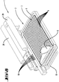
- the Figures 10 to 12 finally show the grill 1 in different views in both the closed and open state.
- the grill 1 here has two plate bases 7, 8, which are flush here, for example. According to this embodiment, an opening (not shown here) can be provided on the lower plate base 7 for discharging liquid from the grill space 2.
- the two plate bases 7, 8 are also, as in the first embodiment according to the Figures 1 to 6 , connected to one another by a hinge mechanism which allows the upper grill plate 4 to move relative to the lower grill plate 3.
Landscapes
- Engineering & Computer Science (AREA)
- Food Science & Technology (AREA)
- Manufacturing & Machinery (AREA)
- Baking, Grill, Roasting (AREA)
Abstract
Description
- Die Erfindung betrifft einen elektrischen Grill mit zwei sich bezogen auf deren große Plattenflächen gegenüberliegenden, gemeinsam einen Grillraum aufspannenden Grillplatten, wobei der Grill eine erste Grillplatte zur Auflage von Grillgut und eine relativ zu der ersten Grillplatte verlagerbare zweite Grillplatte aufweist, und wobei jeder Grillplatte eine die Grillplatte halternde Plattenbasis zugeordnet ist.
- Elektrische Grills der vorgenannten Art sind im Stand der Technik bekannt. Diese werden oft auch als Kontaktgrill bezeichnet, da zu grillendes Gargut auf zwei gegenüberliegenden Seiten von den Grillplatten kontaktiert und gegart wird. Zumeist ist eine der beiden Grillplatten, vorzugsweise die bezogen auf einen üblichen Betriebszustand obere Grillplatte, relativ zu der anderen Grillplatte verlagerbar, so wie dies beispielsweise auch von Sandwichtoastern, Waffeleisen und dergleichen bekannt ist.
- Das US-Design
US D697360 S - Nachteilig bei derartigen Grills ist, dass es bei Verwenden von unterschiedlich hohem Grillgut innerhalb des Grillraums zu einem unterschiedlichen Garergebnis kommt, beispielsweise so, dass ein erstes Grillgut bereits durchgegart ist, während ein zweites Grillgut noch halb roh ist. Des Weiteren kann es bei einem zu starken Aufpressen der oberen Grillplatte, beispielsweise zum Ausgleichen einer Höhendifferenz mehrerer gleichzeitig aufgelegter Grillgüter, zu einer Verformung des jeweils höheren Grillgutes kommen, was ebenfalls das Garergebnis beeinträchtigen kann. Zudem kann das Aufpressen zu einem Festbacken des Grillgutes an den Grillplatten führen.
- Ausgehend von dem vorgenannten Stand der Technik ist es Aufgabe der Erfindung, einen elektrischen Grill zu schaffen, bei welchem sowohl einzelne, als auch unterschiedlich dicke Stücke Grillgut optimal gegrillt werden können.
- Zur Lösung der vorgenannten Aufgabe wird vorgeschlagen, dass zumindest eine Grillplatte mindestens ein verlagerbar an der Plattenbasis gehaltertes Plattensegment aufweist, welches in Abhängigkeit von einer Größe und/oder Form eines in den Grillraum eingebrachten Grillgutes automatisch relativ zu der dieses Plattensegment halternden Plattenbasis verlagerbar ist.
- Erfindungsgemäß kann die Höhe zumindest eines Teilbereiches einer Grillplatte nun an die Höhe eines zu garenden Grillgutes angepasst werden. Es ist in diesem Sinne beispielsweise möglich, dass eine Grillplatte ein relativ zu der Plattenbasis feststehendes Plattensegment und ein verlagerbar an der Plattenbasis gehaltertes Plattensegment aufweist. Darüber hinaus kann auch eine durch ein einziges Plattensegment gebildete Grillplatte insgesamt relativ zu der Plattenbasis verlagert werden, so dass die Höhe des Plattensegmentes sowohl bei der Auflage eines relativ dünnen, als auch bei der Auflage eines dickeren Stückes Grillgut auf die Grillplatte so angepasst werden kann, dass der Grillraum stets optimal geschlossen ist. Bei einer Ausbildung, bei welcher ein erstes Plattensegment relativ zu einem zweiten Plattensegment verlagerbar ist, wird vorteilhaft erreicht, dass mehrere in dem Grillraum befindliche Gargüter gleichermaßen bündig und mit vorzugsweise homogen angreifendem Druck der Grillplatte gehalten werden.
- Es kann vorgesehen sein, dass die Plattenbasis topfförmig ausgebildet ist, wobei das Plattensegment zumindest teilweise in die Plattenbasis hinein verlagerbar ist. Unter topfförmig werden Formen verstanden, die dreidimensionale Räume einseitig offen begrenzen. Durch diese Ausgestaltung kann ein Teilbereich der Grillplatte in die Plattenbasis hineinragen und ein weiterer Teilbereich ggf. über eine Öffnungsebene der Grillplattenbasis hervorstehen, nämlich in Richtung der jeweils gegenüberliegenden Grillplatte bzw. Plattenbasis. Die Plattenbasis kann vorzugsweise zur Führung eines oder mehrerer verlagerbarer Plattensegmente dienen. Insbesondere kann es auch vorgesehen sein, dass ein innerer Randbereich der Plattenbasis Führungen für die Verlagerungsbewegung eines Plattensegmentes bereitstellt. Des Weiteren kann es auch vorgesehen sein, dass ein Plattensegment oder mehrere Plattensegmente in einer geöffneten Stellung des Grillraumes über einen Rand der topfförmigen Grillplattenbasis hinausragen und durch den Schließvorgang, d.h. das Aneinanderführen der gegenüberliegenden Plattenbasen, in die zugeordnete Plattenbasis hineinverlagert werden. Dies kann entweder durch Kontakt der gegenüberliegenden Grillplatten verursacht sein, oder durch eine Anlage eines oder mehrerer Plattensegmente an einem Grillgut. Vorzugsweise wird der Grillraum durch die aneinanderliegenden Grillplattenbasen und/oder Grillplatten so geschlossen, dass aus dem Grillgut austretende Flüssigkeiten aufgefangen und gezielt abgeleitet werden können, sowie eine optimale Temperatur für den Garprozess bereitgestellt werden kann.
- Insbesondere kann vorgesehen sein, dass die Grillplatte mehrere relativ zueinander und relativ zu der jeweils zugeordneten Plattenbasis verlagerbare Plattensegmente aufweist. Diese Ausgestaltung ist besonders vorteilhaft, da mehrere Bereiche einer Grillplatte an die Dicke eines aufgelegten Grillgutes angepasst werden können. Somit ist es auch möglich, beispielsweise mehr als zwei Grillgüter mit unterschiedlicher Höhe optimal in dem elektrischen Grill zuzubereiten, wobei jedes Plattensegment automatisch und unabhängig von benachbarten Plattensegmenten auf eine optimale Plattenhöhe eingestellt werden kann, damit sich die gegenüberliegenden Plattensegmente optimal an das dazwischen platzierte Grillgut anlegen. Es ergibt sich somit die Funktion eines 3D-Nagelbretts mit einer Mehrzahl von bei Krafteinwirkung zurückweichenden Segmenten. Grundsätzlich reicht es aus, wenn nur eine der Grillplatten derartig verlagerbare Plattensegmente aufweist. Allerdings ist es auch möglich, dass beide gegenüberliegenden Grillplatten verlagerbare Plattensegmente aufweisen. Gemäß einer Ausführung kann nur die obere Grillplatte des elektrischen Grills derart segmentiert ausgeführt sein, so dass die Höhe des Grillraumes, d.h. die innenliegende Öffnungshöhe, über einen Teil oder die gesamte Fläche variiert werden kann. Die untere Grillplatte kann ebenfalls segmentiert ausgeführt sein, dies ist wie zuvor erläutert jedoch nicht zwingend erforderlich. In einem geschlossenen Zustand des Grillraumes liegen die sich gegenüberliegenden Plattensegmente vorzugsweise in einem Rahmen der Plattenbasis auf, so dass der elektrische Grill auch bei Segmentierung der Grillplatte mit nur einem einzigen Handgriff geöffnet werden kann.
- Des Weiteren wird vorgeschlagen, dass dem Plattensegment ein Rückstellelement zugeordnet ist, welches das Plattensegment elastisch an der Plattenbasis lagert. Jedem Plattensegment kann beispielsweise ein Federelement zugeordnet sein, welches durch eine angreifende Kraft gespannt werden kann. Sofern sich zwischen den Grillplatten beispielsweise ein Grillgut befindet, das eine definierte Schließstellung des Grillraums verhindert, oder über die Ebenen anderer Grillgüter hervorsteht, wird das Plattensegment gegen die Rückstellkraft des Federelementes verlagert, bis die angreifende Kraft nachlässt, weil der Überstand des betreffenden Grillgutes beseitigt ist. Die Federelemente können beispielsweise Spiralfedern, Blattfedern oder ähnliche Federelemente sein. Darüber hinaus ist es auch möglich, das Plattensegment auf einem Körper aus einem federelastischen Material zu lagern oder das Plattensegment selbst aus einem federelastischen Material auszubilden. Die elastische Lagerung der Plattensegmente, d.h. das Aufbringen einer Vorspannkraft auf die Plattensegmente, sorgt dafür, dass die Plattensegmente in eine vorgelagerte Ausgangsstellung zurückverlagert werden, wenn keine Kraft mehr an den Plattensegmenten angreift, d.h. der Grillraum geöffnet ist und/oder kein Grillgut an dem jeweiligen Plattensegment anliegt und/oder die aufgelegten Grillgüter gleiche Dicken aufweisen, so dass die Grillplatten bei Schließen des Grillraums in einer gleichen Höhenebene an den Grillgütern anliegen.
- Des Weiteren kann vorgesehen sein, dass ein Plattensegment der zweiten Grillplatte aufgrund einer an dem Plattensegment angreifenden Schwerkraft relativ zu der zugeordneten Plattenbasis verlagerbar ist. Die zweite, d.h. obere, Grillplatte kann somit alternativ oder zusätzlich zu einer Rückstellung der Plattensegmente durch ein Federelement, beispielsweise auch Plattensegmente aufweisen, die so an der Plattenbasis gelagert sind, dass diese der Schwerkraft folgend nach unten fallen, wenn die Grillplatte im Wesentlichen horizontal orientiert ist, d.h. die Plattensegmente innerhalb der Plattenbasis senkrecht nach unten zeigen. Ausgehend von einer geöffneten Stellung des Grillraums kann eine frühzeitige horizontale Stellung der oberen Grillplatte durch eine Scharnierlösung zwischen den beiden Plattenbasen erreicht werden, welche die Plattenbasen nicht nur über eine einzige Drehachse miteinander verbindet, sondern einen Hebel mit zwei verschiedenen Drehachsen aufweist, so dass die obere Grillplatte unabhängig von einer aktuellen Stellung während eines Schließvorgangs frühzeitig oder stets parallel zu der unteren Plattenbasis ausgerichtet sein kann. Eine solche Schließmechanik ist im Übrigen verglichen mit einer Verbindung mit nur einer einzigen Drehachse deswegen vorteilhaft, weil das in dem Grillraum befindliche Grillgut nicht zunächst einseitig, d.h. von der Scharnierseite aus, zusammengequetscht wird. Vielmehr kann der Druck der oberen Grillplatte homogen auf das Grillgut aufgebracht werden.
- Es wird vorgeschlagen, dass ein Plattensegment eine Kontaktfläche für Grillgut bereitstellt, deren Flächengröße einen Betrag von 1 mm2 bis 1000 cm2, insbesondere 20 mm2 bis 200 cm2, aufweist. Die Grillplatte kann somit eine Vielzahl von nadelförmigen Plattensegmenten aufweisen, welche nach der Art eines Nagelbretts nebeneinanderliegen und gegen das Grillgut drücken. Die Grillplatte kann alternativ oder zusätzlich auch Plattensegmente aufweisen, welche geeignet sind, Grillgut üblicher Flächengröße, beispielsweise Fleischstücke, Gemüse und dergleichen, vollständig und ohne Mitwirkung benachbarter Plattensegmente aufzunehmen. Abhängig von der gewählten Größe des einzelnen Plattensegmentes kann die Grillplatte so ausgebildet sein, dass sich die Grillplatte durch eine Mehrzahl von Plattensegmenten an die Flächenkontur eines Grillgutes anpasst, so dass die Fläche der jeweiligen Grillplatte optimal zur Auflage von Grillgut genutzt werden kann. Insbesondere ist es auch möglich, dass die Plattensegmente einer Grillplatte unterschiedliche Größen aufweisen, so dass es Flächenbereiche geben kann, welche größere oder kleinere Plattensegmente aufweisen als andere Flächenbereiche. Somit kann ein Teilbereich der Grillplatte für die Auflage von großem Grillgut genutzt werden, während andere Plattensegmente zur Auflage von demgegenüber kleinerem Grillgut vorteilhaft sind. Die angegebenen Flächengrößen für die Plattensegmente sind hier als vorzugsweise vorgeschlagen, wobei ein Betrag von 1 mm2 eine Flächengröße bezeichnet, wie sie bei Nadelspitzen üblich sind, so dass eine Kontur eines Grillguts besonders präzise abgeformt werden kann. Die angegebenen Flächengrößen von bis zu ca. 1000 cm2 geben demgegenüber größere Teilbereiche einer Grillplatte an, welche als ein einziges Plattensegment ausgestaltet sind. In einem Fall kann die Grillplatte beispielsweise auch als Ganzes, d.h. als ein einziges Plattensegment, relativ zu der zugeordneten Plattenbasis verlagerbar sein. Die Grillplatte kann vorzugsweise je nach der Größe des aufgelegten Grillguts als Ganzes in eine topfförmige Plattenbasis eingefahren werden, um ein bündiges Schließen des Grillraumes zu ermöglichen. Vorzugsweise bieten sich Flächengrößen eines Plattensegmentes zwischen 20 mm2 und 200 cm2 an, was ungefähr den Flächengrößen üblicher Grillgüter wie Fleischstücke, Gemüsestücke oder ähnlichem entspricht.
- In diesem Zusammenhang kann auch vorgesehen sein, dass eine Grillplatte ein Plattensegment bis eintausend Plattensegmente aufweist. Insbesondere kann die Grillplatte zwei bis einhundert Plattensegmente aufweisen, besonders bevorzugt zwei bis zehn Plattensegmente. Je nach der Größe des elektrischen Grills ergeben sich abhängig von der Anzahl der Plattensegmente pro Grillplatte dann auch unterschiedlich große Flächen der Plattensegmente. Insgesamt ist die Anzahl der Plattensegmente und deren Größe aufeinander abzustimmen, wobei wie zuvor erläutert Ausführungsformen möglich sind, bei welchen unterschiedliche Flächenbereiche einer Grillplatte unterschiedlich große und unterschiedlich viele Plattensegmente aufweisen.
- Es kann vorgesehen sein, dass eine Grillplatte zumindest zwei Plattensegmente aufweist, wobei jedem der beiden Plattensegmente eine eigene Heizeinrichtung zugeordnet ist, wobei die Heizeinrichtungen der Plattensegmente in Bezug auf einen Betriebsstatus und/oder eine Heizleistung und/oder eine Heizdauer unabhängig voneinander steuerbar sind. Durch diese Ausgestaltung kann die Temperatur eines Plattensegmentes individuell und unabhängig von der Temperatur anderer Plattensegmente eingestellt werden. Beispielsweise kann jedem Plattensegment oder auch einer Gruppe mehrerer Plattensegmente ein Heizelement zugeordnet sein, welches individuell bestromt werden kann. Auf diese Weise können unterschiedliche Heizleistungen und/oder verschiedene Temperaturverläufe und damit auch verschiedene Garpunkte verschiedener Gargüter berücksichtigt werden. Besonders vorzugsweise können sowohl die Plattensegmente der ersten Grillplatte als auch die Plattensegmente der zweiten Grillplatte unabhängig voneinander geheizt werden. Dies betrifft beispielsweise deren Betriebsstatus, d.h. beispielsweise einen aktuellen An-/AusZustand, eine Heizleistung oder eine Heizdauer, welche für ein eine gewisse Dicke aufweisendes Gargut vorgesehen ist. Die Heizeinrichtung eines Plattensegmentes kann manuell durch einen Nutzer geschaltet werden, indem dieser beispielsweise bestimmte Flächenbereiche der Grillplatte anschaltet und andere, welche aufgrund der Menge und Größe des Grillguts nicht benötigt werden, ausgeschaltet lässt. Alternativ kann eine Heizeinrichtung auch automatisiert gesteuert werden, beispielsweise durch einen Kontaktsensor und/oder eine Wägeeinrichtung, welche die Anwesenheit und/oder ein Gewicht und/oder ein Volumen und/oder eine Größe des Garguts messen bzw. abschätzen.
- In diesem Zusammenhang wird vorgeschlagen, dass einem Plattensegment ein Sensor zur Detektion einer Verlagerung oder eines Verlagerungszustandes des Plattensegmentes oder zur Detektion einer Anwesenheit von Grillgut an einer Kontaktfläche des Plattensegmentes zugeordnet ist. Der Sensor kann in einem einfachen Fall als Kontaktsensor ausgebildet sein, welcher bei Detektion eines Kontakts auf eine Anwesenheit von Grillgut an dem jeweiligen Plattensegment schließt. Des Weiteren kann der Sensor auch eine Verlagerung, d.h. eine sich ändernde Höhe des Plattensegmentes relativ zu einer Plattenbasis detektieren oder eine Verlagerungsbewegung durch beispielsweise eine Beschleunigungssensor, einen sich ändernden Widerstand oder dergleichen.
- Des Weiteren ist es besonders vorteilhaft, wenn der elektrische Grill eine Steuereinrichtung aufweist, die eingerichtet ist, eine einem Plattensegment zugeordnete Heizeinrichtung in Abhängigkeit von einem Detektionsergebnis des Sensors zu steuern. Gemäß dieser Ausgestaltung schaltet die Steuereinrichtung diejenige Heizeinrichtung an, welche einem aktuell benötigten oder mehreren Plattensegmenten zugeordnet ist. Plattensegmente, auf welchen aktuell kein Grillgut platziert ist, bleiben demgegenüber ausgeschaltet. Dies reduziert den Stromverbrauch für den Betrieb des elektrischen Grills. Des Weiteren kann die Steuereinrichtung auch die Höhe eines aufliegenden Grillgutes ermitteln, indem beispielsweise ein Abstand zwischen gegenüberliegenden Plattensegmenten des Grillraumes ermittelt wird. Des Weiteren kann die Steuereinrichtung für die Einstellung der Heizleistung bzw. die Einstellung einer voraussichtlichen Heizdauer auch eine Information über die Art eines Gargutes, dessen Garpunkt und dergleichen berücksichtigen, so dass unterschiedliche Gargüter zum gleichen Zeitpunkt einen optimalen Garpunkt erreichen und somit gleichzeitig serviert werden können. Gegebenenfalls kann ein Nutzer der Steuereinrichtung Informationen über die Art des Grillgutes und/oder dessen Gewicht oder dergleichen übermitteln. Des Weiteren kann die Steuereinrichtung auch eine Warmhaltefunktion oder einen Wartemodus steuern, der geschaltet wird, wenn ein Gargut fertiggegart ist. Somit können beispielsweise Grillgüter warmgehalten werden, bis andere Gerichte fertig sind.
- Schließlich wird vorgeschlagen, dass eine der Grillplatten bezogen auf einen geschlossenen Zustand des Grillraumes mit einem Randbereich über die andere Grillplatte und/oder die Plattenbasis hervorsteht, so dass in dem Grillraum vorhandene Flüssigkeit ausströmen kann. Es kann vorgesehen sein, dass die erste, d.h. untere Grillplatte über die obere zweite Grillplatte hervorsteht. Die hervorstehende Grillplatte dient für ein optimales Ablaufen von Flüssigkeiten aus dem Grillraum. Durch den Überstand einer der Grillplatten bildet sich ein Spalt zwischen diesen. Dem Spalt kann ein Auffangbehälter zugeordnet sein, in welchen die Flüssigkeit entsprechend überführt wird.
- Im Folgenden wird die Erfindung anhand von Ausführungsbeispielen näher erläutert. Es zeigen:
- Fig. 1
- einen erfindungsgemäßen Grill gemäß einer ersten Ausführungsform,
- Fig. 2
- eine Draufsicht auf den Grill in einem geschlossenen Zustand,
- Fig. 3
- einen Schnitt durch den geschlossenen Grill,
- Fig. 4
- einen zu
Fig. 3 orthogonalen Schnitt des Grills, - Fig. 5
- eine Prinzipskizze zueinander verlagerbarer Plattensegmente des Grills,
- Fig. 6
- eine weitere geschnittene Ansicht des Grills,
- Fig. 7
- einen erfindungsgemäßen Grill gemäß einer zweiten Ausführungsform,
- Fig. 8
- einen Schnitt durch den Grill gemäß
Fig. 7 , - Fig. 9
- eine Prinzipskizze mit relativ zueinander verlagerbaren Plattensegmenten,
- Fig. 10
- den Grill in einem geschlossenen Zustand,
- Fig. 11
- eine Seitenansicht des Grills in einem geöffneten Zustand,
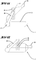
- Fig. 12
- eine Seitenansicht des Grills in einem geschlossenen Zustand.
- Die Figuren zeigen lediglich beispielhaft unterschiedliche mögliche Ausführungsformen eines erfindungsgemäßen Grills, wobei die
Figuren 1 bis 6 eine erste Ausführungsform betreffen und dieFiguren 7 bis 12 eine zweite Ausführungsform betreffen. Es sind selbstverständlich auch weitere erfindungsgemäße Ausführungsformen denkbar, wobei die hier getroffene Auswahl nicht beschränkend zu verstehen ist. - Der in
Fig. 1 dargestellte Grill 1 weist zwei gegenüberliegende Grillplatten 3, 4 auf. Jede der Grillplatten 3, 4 ist in einer Plattenbasis 7, 8 gehaltert, wobei die Plattenbasen 7, 8 durch eine Mechanik mit einem Scharnier 27 relativ zueinander verlagerbar sind. Das Scharnier 27 weist einen Hebel 28 auf, welcher in eine an einer gegenüberliegenden Grillplatte 4 gehalterte Führung 29 eingreift. In diese Führung 29 greift ebenfalls ein Führungselement 30 der Grillplatte 4 ein. Die Scharniermechanik ermöglicht eine Bewegung der oberen Grillplatte 4 relativ zu zwei verschiedenen Rotationsachsen, so dass die obere Grillplatte 4 relativ zu der unteren Grillplatte 3 nicht nur verschwenkt, sondern auch linear verlagert werden kann. Die beiden gegenüberliegenden Grillplatten 3, 4 spannen zwischen sich einen Grillraum 2 auf, in welchen Grillgut 5, 6 eingebracht ist. Hier befinden sich zwei Grillgüter 5, 6 innerhalb des Grillraumes 2, wobei ein erstes Grillgut 5 eine andere Höhe aufweist als ein zweites Grillgut 6. - Die Grillplatten 3, 4 weisen mehrere Plattensegmente 9 bis 16 auf, wobei die untere Grillplatte 3 vier Plattensegmente 9 bis 12 aufweist, und wobei die obere Grillplatte 4 ebenfalls vier Plattensegmente 13 bis 16 aufweist. Die Plattensegmente 9 bis 12 der unteren Grillplatte 3 sind relativ zu der zugeordneten Plattenbasis 7 ortsfest, während die Plattensegmente 13 bis 16 der oberen Grillplatte 4 relativ zu deren Plattenbasis 8 verlagert werden können, nämlich in die Plattenbasis 8 hinein, was hier beispielsweise einer Verlagerungsbewegung orthogonal zu der Plattenebene der Plattenbasis 8 entspricht. Die obere Grillplatte 4 kann relativ zu der unteren Grillplatte 3 verlagert werden, indem ein Nutzer an einem an der oberen Grillplatte 4 ausgebildeten Griff 26 angreift und die obere Grillplatte 4 in eine gewünschte Stellung verlagert.
-
Fig. 2 zeigt eine Draufsicht auf den inFig. 1 gezeigten Grill 1. Zu erkennen ist, dass der Griff 26 über die Kontur des Grills 1 hervorsteht, so dass der Nutzer beim Angreifen an dem Griff 26 nicht in Kontakt mit beispielsweise der oberen Grillplatte 4 gelangen kann und auch bei einem Öffnen des Grillraums 2 keine Hitzeeinwirkung erleidet. -
Fig. 3 zeigt eine geschnittene Ansicht des Grills 1 gemäß der inFig. 2 bezeichneten Schnittlinie III. Der Grill 1 ist in einer senkrechten Ebene geschnitten, welche die gegenüberliegenden Plattensegmente 10 und 14 der unteren bzw. oberen Grillplatten 3, 4 schneidet. Die Plattenbasis 8 der oberen Grillplatte 4 und damit auch das Plattensegment 14 der oberen Grillplatte 4 ist länger ausgebildet als die untere Plattenbasis 7 bzw. das untere Plattensegment 10. Dadurch greift ein Randbereich 25 des oberen Plattensegmentes 14 über die untere Plattenbasis 7 hervor, so dass in dem Grillraum 2 vorhandene Flüssigkeit, welche durch die darin befindlichen Grillgüter 5, 6 bedingt ist, aus dem Grillraum 2 herausfließen bzw. abgeführt werden kann. Zum Auffangen der Flüssigkeit kann eine hier nicht dargestellte Flüssigkeitsauffangeinrichtung vorgesehen sein, beispielsweise ein Behälter, welcher neben der unteren Plattenbasis 7 platziert wird. -
Fig. 4 zeigt einen Schnitt durch den Grill 1 gemäß der inFig. 2 dargestellten Linie IV. Der Grillraum 2 ist mit den beiden unterschiedlich hohen Grillgütern 5, 6 bestückt, wobei ein erstes Grillgut 5 zwischen den Plattensegmenten 9 und 13 der unteren bzw. oberen Grillplatte 3, 4 liegt, und wobei ein zweites, dickeres Grillgut 6 zwischen den Plattensegmenten 11 und 15 der unteren bzw. oberen Grillplatte 3, 4 liegt. Die anderen Plattensegmente 10, 12, 14, 16 weisen kein Grillgut auf. Jedem der Plattensegmente 9 bis 16 ist eine eigene Heizeinrichtung 17 bis 24 zugeordnet. Jede der Heizeinrichtungen 17 bis 24 kann unabhängig von den anderen Heizeinrichtungen 17 bis 24 geschaltet werden. Hier sind die Heizeinrichtungen 17 bis 24 beispielsweise als Heizwiderstände ausgebildet. Der Grill 1 weist eine Steuereinrichtung auf, welche eingerichtet ist, die Heizeinrichtungen 17 bis 24 zu schalten. Die Plattensegmente 13 und 15 der oberen Grillplatte 4 sind inFig. 4 korrespondierend zu den Dicken der aufgelegten Grillgüter 5, 6 verlagert. Die den Plattensegmenten 13 bis 16 der oberen Grillplatte 4 zugeordnete Plattenbasis 8 ist im Wesentlichen topfförmig ausgebildet, so dass die Plattensegmente 13 bis 16 in die obere Plattenbasis 8 hinein verlagert werden können. Die Plattensegmente 9 bis 12 der unteren Grillplatte 3 sind hingegen ortsfest an der unteren Plattenbasis 7 angeordnet und verlagern sich nicht bei Kontakt mit dem jeweiligen Grillgut 5, 6. Der Abstand zwischen den gegenüberliegenden Plattensegmenten 9 und 13 entspricht der Höhe des Grillgutes 5. Der Abstand der gegenüberliegenden Plattensegmente 11 und 15 entspricht der Höhe des dazwischenliegenden Grillgutes 6. Hier sind die oberen Plattensegmente 13 bis 16 beispielsweise schiebebeweglich an der Plattenbasis 8 gelagert, so dass es bei Kontakt der Plattensegmente 13 bis 16 mit dem Grillgut 5, 6 zu einer Höhenverlagerung relativ zu der Plattenbasis 8 kommt. Den oberen Plattensegmenten 13,16 kann vorzugsweise eine hier nicht dargestellte Sensorik zugeordnet sein, welche die Anwesenheit eines Grillgutes 5, 6 erkennt und die den jeweiligen Plattensegmenten 9, 11, 13, 15 zugeordneten Heizeinrichtungen 17, 19, 21, 23 steuert. Beispielsweise kann ein den Plattensegmenten 9, 11, 13, 15 zugeordneter Kontaktsensor erkennen, dass eine Kraft auf die Plattensegmente 9, 11, 13, 15 ausgeübt wird. Die Steuereinrichtung schließt daraufhin, dass an den Plattensegmenten 9 und 13 bzw. 11 und 15 ein Grillgut 5, 6 anliegt und schaltet die den Plattensegmenten 9, 11, 13, 15 zugeordneten Heizeinrichtungen 17, 19, 21, 23 an. Es kann vorgesehen sein, dass eine weitere Sensorik, beispielsweise eine den unteren Plattensegmenten 9 bis 12 zugeordnete Wägeeinrichtung das Gewicht der Grillgüter 5, 6 misst und dementsprechend eine Temperatur und/oder Heizdauer oder andere Parameter des Garvorgangs steuert. Durch die Verlagerbarkeit der Plattensegmente 13 bis 16 der oberen Grillplatte 4 kommt es stets zu einer beiderseitigen Anlage der Plattensegmente 9, 13 bzw. 10, 14, bzw. 11, 15, bzw. 12, 16 an einem dazwischen angeordneten Grillgut 5, 6. Dadurch wird vermieden, dass ein erstes Grillgut 5, welches eine geringere Höhe aufweist als ein zweites Grillgut 6, in Kontakt mit der oberen Grillplatte 4 gelangt. Vielmehr wird die Höhenposition der oberen Plattensegmente 13 bis 16 an die Höhe des jeweiligen Grillgutes 5, 6 angepasst, so dass ein homogener Garerfolg für unterschiedlich hohe Grillgüter 5, 6 sichergestellt werden kann. -
Fig. 5 zeigt eine Prinzipskizze der segmentierten Grillplatten 3, 4, wobei die Höhenebenen der verlagerten oberen Plattensegmente 13, 15 erkennbar sind. -
Fig. 6 zeigt eine dreidimensionale Schnittdarstellung des Grills 1, welche den Aufbau des Grills 1 weiter verdeutlicht. Zu erkennen sind die verschiedenen Höhenebenen der Plattensegmente 9 bis 16 der beiden Grillplatten 3, 4 sowie die den Plattensegmenten 9 bis 16 zugeordneten Heizeinrichtungen 17 bis 24. Alternativ zu der hier gezeigten Ausführungsform kann es selbstverständlich auch vorgesehen sein, dass eine Heizeinrichtung 17 bis 24 mehrere Plattensegmente 9 bis 16 gleichzeitig heizt, oder dass mehrere Heizeinrichtungen 17 bis 24 ein bestimmtes Plattensegment 9 bis 16 heizen. - Die
Figuren 7 bis 11 zeigen einen zweiten erfindungsgemäßen Grill 1, bei welchem beide Grillplatten 3, 4 eine sehr große Vielzahl von Plattensegmenten 9 bzw. 13 aufweisen. Die Plattensegmente 9, 13 sind hier im Vergleich zu den Plattensegmenten 9 bis 16 gemäß der zuvor in denFiguren 1 bis 6 dargestellten Ausführungsform wesentlich kleiner. Durch die kleinere Fläche der einzelnen Plattensegmente 9, 13 kann die Kontur eines innerhalb des Grillraums 2 befindlichen Grillgutes 5 wesentlich genauer nachgebildet werden, so dass die Fläche der Grillplatten 3, 4 ggf. platzsparender genutzt werden kann und an viele verschiedene Flächengrößen von Grillgut 5 angepasst werden kann. Die einzelnen Plattensegmente 9, 13 sind hier sowohl bezogen auf die untere Grillplatte 3, als auch bezogen auf die obere Grillplatte 4 alle relativ zu der jeweils zugeordneten Plattenbasis 7, 8 verlagerbar. Dabei kann die Verlagerbarkeit entweder durch Drücken des Grillgutes 5 gegen die jeweiligen Plattensegmente 9, 13 erreicht werden, wobei den Plattensegmenten 9 der unteren Plattenbasis 7 vorzugsweise ein Federelement zugeordnet ist, welches die unbelasteten Plattensegmente 9 in eine Ausgangsstellung zurückverlagert, die einer in Richtung der oberen Plattenbasis 8 verlagerten Stellung entspricht. Sofern ein Grillgut 5 auf die Plattensegmente aufgelegt wird, kann die Gewichtskraft des Grillgutes 5 bzw. die Gewichtskraft der gegenüberliegenden Plattensegmente 13 die Rückstellkraft des Federelementes überwinden, so dass diese in die untere Plattenbasis 7 hineinverlagert werden. Die Plattensegmente 13 der oberen Grillplatte 4 können vorzugsweise zumindest unterstützend durch die an den Plattensegmenten 13 angreifende Gewichtskraft in Richtung der unteren Grillplatte 3 verlagert werden. Alternativ oder zusätzlich kann auch den oberen Plattensegmenten 13 jeweils ein Federelement zugeordnet sein, welches die Plattensegmente 13 in eine aus der topfförmigen Plattenbasis 8 heraus verlagerten Stellung positioniert. -
Fig. 8 zeigt einen Schnitt durch den Grill 1 gemäßFig. 7 . Erkennbar ist wiederum eine Heizeinrichtung 17, welche den Plattensegmenten 9 zugeordnet ist. In gleicher Art und Weise kann auch die obere Grillplatte 4 eine Heizeinrichtung 21 aufweisen. Hier sind beispielsweise eine Vielzahl von Plattensegmenten 9 einer gemeinsamen Heizeinrichtung 17 zugeordnet. Es kann jedoch auch vorgesehen sein, jedem Plattensegment 9 eine eigene Heizeinrichtung 17 zuzuordnen. Eine Steuereinrichtung des Grills 1 kann beispielsweise ausgebildet sein, um einen Kontakt der Plattensegmente 9, 13 durch ein Grillgut 5 zu erkennen und eine ortskorrespondierende Heizeinrichtung 17, 21 einzuschalten. -
Fig. 9 zeigt eine Prinzipskizze der Grillplatten 3, 4, deren Plattensegmente 9, 13 an eine Form, insbesondere Außenkontur und Dicke, eines Grillgutes 5 angepasst sind. Je kleiner die Kontaktfläche der Plattensegmente 9, 13 ist, desto genauer kann die Kontur des Grillgutes 5 nachgebildet werden. - Die
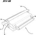
Figuren 10 bis 12 zeigen den Grill 1 schließlich in verschiedenen Ansichten in sowohl geschlossenem als auch geöffnetem Zustand. Der Grill 1 weist hier zwei Plattenbasen 7, 8 auf, welche hier beispielsweise zueinander bündig abschließen. Zum Auslassen von Flüssigkeit aus dem Grillraum 2 kann gemäß dieser Ausführungsform beispielsweise eine hier nicht dargestellte Öffnung an der unteren Plattenbasis 7 vorgesehen sein. Die beiden Plattenbasen 7, 8 sind darüber hinaus, wie auch bei der ersten Ausführungsform gemäß denFiguren 1 bis 6 , durch eine Scharniermechanik miteinander verbunden, die eine Beweglichkeit der oberen Grillplatte 4 relativ zu der unteren Grillplatte 3 erlaubt. -
1 Grill 27 Scharnier 2 Grillraum 28 Hebel 3 Grillplatte 29 Führung 4 Grillplatte 30 Führungselement 5 Grillgut 6 Grillgut 7 Plattenbasis 8 Plattenbasis 9 Plattensegment 10 Plattensegment 11 Plattensegment 12 Plattensegment 13 Plattensegment 14 Plattensegment 15 Plattensegment 16 Plattensegment 17 Heizeinrichtung 18 Heizeinrichtung 19 Heizeinrichtung 20 Heizeinrichtung 21 Heizeinrichtung 22 Heizeinrichtung 23 Heizeinrichtung 24 Heizeinrichtung 25 Randbereich 26 Griff
Claims (11)
- Elektrischer Grill (1) mit zwei sich bezogen auf deren große Plattenflächen gegenüberliegenden, gemeinsam einen Grillraum (2) aufspannenden Grillplatten (3, 4), wobei der Grill (1) eine erste Grillplatte (3) zur Auflage von Grillgut (5, 6) und eine relativ zu der ersten Grillplatte (3) verlagerbare zweite Grillplatte (4) aufweist, und wobei jeder Grillplatte (3, 4) eine die Grillplatte (3, 4) halternde Plattenbasis (7, 8) zugeordnet ist, dadurch gekennzeichnet, dass zumindest eine Grillplatte (3, 4) mindestens ein verlagerbar an der Plattenbasis (7, 8) gehaltertes Plattensegment (9 bis 16) aufweist, welches in Abhängigkeit von einer Größe und/oder Form eines in den Grillraum (2) eingebrachten Grillgutes (5, 6) automatisch relativ zu der dieses Plattensegment (9 bis 16) halternden Plattenbasis (7, 8) verlagerbar ist.
- Elektrischer Grill (1) nach Anspruch 1, dadurch gekennzeichnet, dass die Plattenbasis (7, 8) topfförmig ausgebildet ist, wobei das Plattensegment (9 bis 16) zumindest teilweise in die Plattenbasis (7, 8) hinein verlagerbar ist.
- Elektrischer Grill (1) nach Anspruch 1 oder 2, dadurch gekennzeichnet, dass die Grillplatte (3, 4) mehrere relativ zueinander und relativ zu der jeweils zugeordneten Plattenbasis (7, 8) verlagerbare Plattensegmente (9 bis 16) aufweist.
- Elektrischer Grill (1) nach einem der vorhergehenden Ansprüche, dadurch gekennzeichnet, dass dem Plattensegment (9 bis 16) ein Rückstellelement zugeordnet ist, welches das Plattensegment (9 bis 16) elastisch an der Plattenbasis (7, 8) lagert.
- Elektrischer Grill (1) nach einem der vorhergehenden Ansprüche, dadurch gekennzeichnet, dass ein Plattensegment (13 bis 16) der zweiten Grillplatte (4) aufgrund einer an dem Plattensegment (13 bis 16) angreifenden Schwerkraft relativ zu der zugeordneten Plattenbasis (8) verlagerbar ist.
- Elektrischer Grill (1) nach einem der vorhergehenden Ansprüche, dadurch gekennzeichnet, dass ein Plattensegment (9 bis 16) eine Kontaktfläche für Grillgut bereitstellt, deren Flächengröße einen Betrag von 1 mm2 bis 1000 cm2, insbesondere 20 mm2 bis 200 cm2, aufweist.
- Elektrischer Grill (1) nach einem der vorhergehenden Ansprüche, dadurch gekennzeichnet, dass eine Grillplatte (3, 4) ein Plattensegment (9 bis 16) bis eintausend Plattensegmente (9 bis 16), insbesondere zwei bis einhundert Plattensegmente (9 bis 16), besonders bevorzugt zwei bis zehn Plattensegmente (9 bis 16), aufweist.
- Elektrischer Grill (1) nach einem der vorhergehenden Ansprüche, dadurch gekennzeichnet, dass eine Grillplatte (3,4) zumindest zwei Plattensegmente (9 bis 16) aufweist, wobei jedem der beiden Plattensegmente (9 bis 16) eine eigene Heizeinrichtung (17 bis 24) zugeordnet ist, wobei die Heizeinrichtungen (17 bis 24) der Plattensegmente (9 bis 16) in Bezug auf einen Betriebsstatus und/ oder eine Heizleistung und/oder eine Heizdauer unabhängig voneinander steuerbar sind.
- Elektrischer Grill (1) nach einem der vorhergehenden Ansprüche, dadurch gekennzeichnet, dass einem Plattensegment (9 bis 16) ein Sensor zur Detektion einer Verlagerung oder eines Verlagerungszustandes des Plattensegmentes (9 bis 16) oder zur Detektion einer Anwesenheit von Grillgut (5, 6) an einer Kontaktfläche des Plattensegmentes (9 bis 16) zugeordnet ist.
- Elektrischer Grill (1) nach Anspruch 9, gekennzeichnet durch eine Steuereinrichtung, welche eingerichtet ist, eine einem Plattensegment (9 bis 16) zugeordnete Heizeinrichtung (17 bis 24) in Abhängigkeit von einem Detektionsergebnis des Sensors zu steuern.
- Elektrischer Grill (1) nach einem der vorhergehenden Ansprüche, dadurch gekennzeichnet, dass eine der Grillplatten (3, 4) bezogen auf einen geschlossenen Zustand des Grillraums (2) mit einem Randbereich über die andere Grillplatte (4, 3) und/oder die Plattenbasis (8, 7) hervorsteht, so dass in dem Grillraum (2) vorhandene Flüssigkeit ausströmen kann.
Priority Applications (5)
| Application Number | Priority Date | Filing Date | Title |
|---|---|---|---|
| EP18191930.9A EP3616578B1 (de) | 2018-08-31 | 2018-08-31 | Elektrischer grill mit zwei einen grillraum aufspannenden grillplatten |
| ES18191930T ES2895065T3 (es) | 2018-08-31 | 2018-08-31 | Parrilla eléctrica con dos placas de parrilla que delimitan un área de la parrilla |
| PL18191930T PL3616578T3 (pl) | 2018-08-31 | 2018-08-31 | Elektryczny grill z dwoma płytami grilla tworzącymi przestrzeń grillującą |
| CN201910794856.3A CN110870704B (zh) | 2018-08-31 | 2019-08-27 | 具有两个撑开烧烤空间的烧烤板的电烤架 |
| US16/556,372 US20200069112A1 (en) | 2018-08-31 | 2019-08-30 | Electric grill with two grill plates that define a grilling space |
Applications Claiming Priority (1)
| Application Number | Priority Date | Filing Date | Title |
|---|---|---|---|
| EP18191930.9A EP3616578B1 (de) | 2018-08-31 | 2018-08-31 | Elektrischer grill mit zwei einen grillraum aufspannenden grillplatten |
Publications (2)
| Publication Number | Publication Date |
|---|---|
| EP3616578A1 true EP3616578A1 (de) | 2020-03-04 |
| EP3616578B1 EP3616578B1 (de) | 2021-09-29 |
Family
ID=63452510
Family Applications (1)
| Application Number | Title | Priority Date | Filing Date |
|---|---|---|---|
| EP18191930.9A Active EP3616578B1 (de) | 2018-08-31 | 2018-08-31 | Elektrischer grill mit zwei einen grillraum aufspannenden grillplatten |
Country Status (5)
| Country | Link |
|---|---|
| US (1) | US20200069112A1 (de) |
| EP (1) | EP3616578B1 (de) |
| CN (1) | CN110870704B (de) |
| ES (1) | ES2895065T3 (de) |
| PL (1) | PL3616578T3 (de) |
Cited By (1)
| Publication number | Priority date | Publication date | Assignee | Title |
|---|---|---|---|---|
| DE202024101984U1 (de) | 2024-04-22 | 2024-05-10 | nobellgo UG (haftungsbeschränkt) | Kontaktgrill und Abstandshalter als Zubehör dafür |
Families Citing this family (4)
| Publication number | Priority date | Publication date | Assignee | Title |
|---|---|---|---|---|
| JP1673076S (de) * | 2019-12-30 | 2020-11-24 | ||
| FR3141049B1 (fr) * | 2022-10-24 | 2024-10-25 | Seb Sa | Appareil et procédé de cuisson d’un aliment précuit |
| FR3143306B1 (fr) * | 2022-12-19 | 2025-10-24 | Seb Sa | Procédé de cuisson d’aliments mis en œuvre par un appareil de préparation culinaire |
| WO2025078610A1 (de) * | 2023-10-13 | 2025-04-17 | Amt Alumetall-Giesstechnik Gmbh | Grillpresse zum vollständigen anordnen im garraum eines gargeräts |
Citations (6)
| Publication number | Priority date | Publication date | Assignee | Title |
|---|---|---|---|---|
| US3746837A (en) * | 1972-07-18 | 1973-07-17 | I Frey | Food warming appliance |
| EP1714595A1 (de) * | 2005-04-19 | 2006-10-25 | Electrolux Professional S.P.A. | Gerät zum beidseitigen Kochen von Speisen |
| EP1913853A2 (de) * | 2006-10-17 | 2008-04-23 | Electrolux Professional S.P.A. | Vorrichtung zum schnellen beidseitigen Kochen von Lebensmitteln |
| USD697360S1 (en) | 2012-03-20 | 2014-01-14 | Tefal | Electric grill |
| WO2014144313A1 (en) * | 2013-03-15 | 2014-09-18 | Carrier Commercial Refrigeration, Inc. | Cooking gap control of a cooking apparatus |
| WO2017120293A1 (en) * | 2016-01-07 | 2017-07-13 | Illinois Tool Works, Inc. | Apparatus and method for heating a food product constituted of a sandwich or the like, before it is consumed |
Family Cites Families (12)
| Publication number | Priority date | Publication date | Assignee | Title |
|---|---|---|---|---|
| US4241650A (en) * | 1976-06-07 | 1980-12-30 | Apfelbaum Jerome G | Apparatus for preparing food |
| US5197377A (en) * | 1991-01-08 | 1993-03-30 | Premark Feg Corporation | Apparatus for two-sided cooking |
| US6467400B2 (en) * | 2000-09-15 | 2002-10-22 | Proprocess Corporation | Digitally controlled clamshell press |
| US6736051B2 (en) * | 2001-09-18 | 2004-05-18 | In-N-Out Burgers | Floating clamshell griddle toaster |
| US8833243B2 (en) * | 2006-04-20 | 2014-09-16 | Restaurant Technology, Inc. | Grill including automatic gap calibration |
| CN201213734Y (zh) * | 2008-05-14 | 2009-04-01 | 张尚铁 | 温度可控煎烤器 |
| CN201208186Y (zh) * | 2008-06-18 | 2009-03-18 | 应世林 | 一种悬浮式电饼铛 |
| KR20150013827A (ko) * | 2012-07-09 | 2015-02-05 | 도요세이칸 그룹 홀딩스 가부시키가이샤 | 가열 장치 및 가열 방법 |
| EP2931094B1 (de) * | 2012-12-11 | 2020-12-02 | Garland Commercial Industries, LLC | Kochgrill mit mehrfachen gasheizungszonen von vorne nach hinten für verbesserte grillplattentemperaturregelung |
| CN203234601U (zh) * | 2013-04-12 | 2013-10-16 | 漳州灿坤实业有限公司 | 一种能对食物进行加压的煎烤器 |
| CN203506454U (zh) * | 2013-09-24 | 2014-04-02 | 广东伊立浦电器股份有限公司 | 具有升降机构的煎烤器 |
| CN107374393B (zh) * | 2017-09-01 | 2023-07-14 | 广东百胜图科技有限公司 | 一种具有浮升挡油结构的煎烤器 |
-
2018
- 2018-08-31 ES ES18191930T patent/ES2895065T3/es active Active
- 2018-08-31 PL PL18191930T patent/PL3616578T3/pl unknown
- 2018-08-31 EP EP18191930.9A patent/EP3616578B1/de active Active
-
2019
- 2019-08-27 CN CN201910794856.3A patent/CN110870704B/zh active Active
- 2019-08-30 US US16/556,372 patent/US20200069112A1/en not_active Abandoned
Patent Citations (6)
| Publication number | Priority date | Publication date | Assignee | Title |
|---|---|---|---|---|
| US3746837A (en) * | 1972-07-18 | 1973-07-17 | I Frey | Food warming appliance |
| EP1714595A1 (de) * | 2005-04-19 | 2006-10-25 | Electrolux Professional S.P.A. | Gerät zum beidseitigen Kochen von Speisen |
| EP1913853A2 (de) * | 2006-10-17 | 2008-04-23 | Electrolux Professional S.P.A. | Vorrichtung zum schnellen beidseitigen Kochen von Lebensmitteln |
| USD697360S1 (en) | 2012-03-20 | 2014-01-14 | Tefal | Electric grill |
| WO2014144313A1 (en) * | 2013-03-15 | 2014-09-18 | Carrier Commercial Refrigeration, Inc. | Cooking gap control of a cooking apparatus |
| WO2017120293A1 (en) * | 2016-01-07 | 2017-07-13 | Illinois Tool Works, Inc. | Apparatus and method for heating a food product constituted of a sandwich or the like, before it is consumed |
Cited By (1)
| Publication number | Priority date | Publication date | Assignee | Title |
|---|---|---|---|---|
| DE202024101984U1 (de) | 2024-04-22 | 2024-05-10 | nobellgo UG (haftungsbeschränkt) | Kontaktgrill und Abstandshalter als Zubehör dafür |
Also Published As
| Publication number | Publication date |
|---|---|
| US20200069112A1 (en) | 2020-03-05 |
| PL3616578T3 (pl) | 2022-02-07 |
| EP3616578B1 (de) | 2021-09-29 |
| CN110870704B (zh) | 2024-09-17 |
| CN110870704A (zh) | 2020-03-10 |
| ES2895065T3 (es) | 2022-02-17 |
Similar Documents
| Publication | Publication Date | Title |
|---|---|---|
| EP3616578B1 (de) | Elektrischer grill mit zwei einen grillraum aufspannenden grillplatten | |
| DE112014002750T5 (de) | Topf für langsames Kochen | |
| DE69405586T2 (de) | Elektrischer brotröster mit einem betätigungselement mit freihub | |
| DE69407623T2 (de) | Elektrisches grill- oder wärmegerät für nahrungsmittel, insbesondere brot, mit an beweglichen armen gelagerten rösteinheiten | |
| EP2649914B1 (de) | Tiegeltrennvorrichtung | |
| EP0413036B1 (de) | Vorrichtung zum Erhitzen, Erwärmen oder Warmhalten, insbesondere zum Überbacken von Speisen, insbesondere Salamander | |
| DE7513788U (de) | Elektrischer brotroester | |
| DE1579531C3 (de) | Elektrischer Brotröster | |
| DE102010031011B4 (de) | Vorrichtung zum Herstellen eines Fleischproduktes und zur Verwendung in der Vorrichtung geeignete Formbehälter | |
| EP3449786B1 (de) | Elektrisches tischraclettegerät | |
| EP2853820A1 (de) | Vorrichtung zum Garen von Lebensmitteln | |
| DE2623294C2 (de) | Grillgerät | |
| DE60300638T2 (de) | Brotbackmaschine und Brotbackmaschinensensor | |
| EP0317763B1 (de) | Besteckreinigungsgerät | |
| DE2014024B2 (de) | Elektrischer Toaster | |
| EP3184912A2 (de) | Garauflagevorrichtung zur zubereitung eines garguts | |
| DE2056050B2 (de) | Elektrischer brotroester | |
| DE60003080T2 (de) | Basisgestell für eine automatische kaffeemaschine | |
| WO2005120316A1 (de) | Elektrisches tischgerät zur zubereitung und/oder temperierung von speisen am tisch | |
| DE20108268U1 (de) | Warmspeisenausgabe | |
| DE69205086T2 (de) | Kochgerät mit elektrischer Widerstandsheizung. | |
| EP2989947A1 (de) | Abdeckelement für ein verriegelungselement einer küchenmaschine | |
| WO2010003269A2 (de) | Vorrichtung zum rösten von nahrungsmitteln | |
| DE202014008487U1 (de) | Kleinküchengerät und austauschbare Dekoreinlage für ein Kleinküchengerät zum Erhitzen einer Teigware | |
| DE3001049A1 (de) | Haushaltgeraet mit schalterkasten |
Legal Events
| Date | Code | Title | Description |
|---|---|---|---|
| PUAI | Public reference made under article 153(3) epc to a published international application that has entered the european phase |
Free format text: ORIGINAL CODE: 0009012 |
|
| STAA | Information on the status of an ep patent application or granted ep patent |
Free format text: STATUS: THE APPLICATION HAS BEEN PUBLISHED |
|
| AK | Designated contracting states |
Kind code of ref document: A1 Designated state(s): AL AT BE BG CH CY CZ DE DK EE ES FI FR GB GR HR HU IE IS IT LI LT LU LV MC MK MT NL NO PL PT RO RS SE SI SK SM TR |
|
| AX | Request for extension of the european patent |
Extension state: BA ME |
|
| STAA | Information on the status of an ep patent application or granted ep patent |
Free format text: STATUS: REQUEST FOR EXAMINATION WAS MADE |
|
| 17P | Request for examination filed |
Effective date: 20200814 |
|
| RBV | Designated contracting states (corrected) |
Designated state(s): AL AT BE BG CH CY CZ DE DK EE ES FI FR GB GR HR HU IE IS IT LI LT LU LV MC MK MT NL NO PL PT RO RS SE SI SK SM TR |
|
| GRAP | Despatch of communication of intention to grant a patent |
Free format text: ORIGINAL CODE: EPIDOSNIGR1 |
|
| RIC1 | Information provided on ipc code assigned before grant |
Ipc: A47J 37/06 20060101AFI20210310BHEP |
|
| STAA | Information on the status of an ep patent application or granted ep patent |
Free format text: STATUS: GRANT OF PATENT IS INTENDED |
|
| INTG | Intention to grant announced |
Effective date: 20210415 |
|
| GRAS | Grant fee paid |
Free format text: ORIGINAL CODE: EPIDOSNIGR3 |
|
| GRAA | (expected) grant |
Free format text: ORIGINAL CODE: 0009210 |
|
| STAA | Information on the status of an ep patent application or granted ep patent |
Free format text: STATUS: THE PATENT HAS BEEN GRANTED |
|
| AK | Designated contracting states |
Kind code of ref document: B1 Designated state(s): AL AT BE BG CH CY CZ DE DK EE ES FI FR GB GR HR HU IE IS IT LI LT LU LV MC MK MT NL NO PL PT RO RS SE SI SK SM TR |
|
| REG | Reference to a national code |
Ref country code: GB Ref legal event code: FG4D Free format text: NOT ENGLISH |
|
| REG | Reference to a national code |
Ref country code: DE Ref legal event code: R096 Ref document number: 502018007244 Country of ref document: DE |
|
| REG | Reference to a national code |
Ref country code: CH Ref legal event code: EP Ref country code: AT Ref legal event code: REF Ref document number: 1433485 Country of ref document: AT Kind code of ref document: T Effective date: 20211015 |
|
| REG | Reference to a national code |
Ref country code: IE Ref legal event code: FG4D Free format text: LANGUAGE OF EP DOCUMENT: GERMAN |
|
| REG | Reference to a national code |
Ref country code: LT Ref legal event code: MG9D |
|
| PG25 | Lapsed in a contracting state [announced via postgrant information from national office to epo] |
Ref country code: NO Free format text: LAPSE BECAUSE OF FAILURE TO SUBMIT A TRANSLATION OF THE DESCRIPTION OR TO PAY THE FEE WITHIN THE PRESCRIBED TIME-LIMIT Effective date: 20211229 Ref country code: BG Free format text: LAPSE BECAUSE OF FAILURE TO SUBMIT A TRANSLATION OF THE DESCRIPTION OR TO PAY THE FEE WITHIN THE PRESCRIBED TIME-LIMIT Effective date: 20211229 Ref country code: LT Free format text: LAPSE BECAUSE OF FAILURE TO SUBMIT A TRANSLATION OF THE DESCRIPTION OR TO PAY THE FEE WITHIN THE PRESCRIBED TIME-LIMIT Effective date: 20210929 Ref country code: SE Free format text: LAPSE BECAUSE OF FAILURE TO SUBMIT A TRANSLATION OF THE DESCRIPTION OR TO PAY THE FEE WITHIN THE PRESCRIBED TIME-LIMIT Effective date: 20210929 Ref country code: RS Free format text: LAPSE BECAUSE OF FAILURE TO SUBMIT A TRANSLATION OF THE DESCRIPTION OR TO PAY THE FEE WITHIN THE PRESCRIBED TIME-LIMIT Effective date: 20210929 Ref country code: HR Free format text: LAPSE BECAUSE OF FAILURE TO SUBMIT A TRANSLATION OF THE DESCRIPTION OR TO PAY THE FEE WITHIN THE PRESCRIBED TIME-LIMIT Effective date: 20210929 Ref country code: FI Free format text: LAPSE BECAUSE OF FAILURE TO SUBMIT A TRANSLATION OF THE DESCRIPTION OR TO PAY THE FEE WITHIN THE PRESCRIBED TIME-LIMIT Effective date: 20210929 |
|
| REG | Reference to a national code |
Ref country code: NL Ref legal event code: MP Effective date: 20210929 |
|
| REG | Reference to a national code |
Ref country code: ES Ref legal event code: FG2A Ref document number: 2895065 Country of ref document: ES Kind code of ref document: T3 Effective date: 20220217 |
|
| PG25 | Lapsed in a contracting state [announced via postgrant information from national office to epo] |
Ref country code: LV Free format text: LAPSE BECAUSE OF FAILURE TO SUBMIT A TRANSLATION OF THE DESCRIPTION OR TO PAY THE FEE WITHIN THE PRESCRIBED TIME-LIMIT Effective date: 20210929 Ref country code: GR Free format text: LAPSE BECAUSE OF FAILURE TO SUBMIT A TRANSLATION OF THE DESCRIPTION OR TO PAY THE FEE WITHIN THE PRESCRIBED TIME-LIMIT Effective date: 20211230 |
|
| PG25 | Lapsed in a contracting state [announced via postgrant information from national office to epo] |
Ref country code: IS Free format text: LAPSE BECAUSE OF FAILURE TO SUBMIT A TRANSLATION OF THE DESCRIPTION OR TO PAY THE FEE WITHIN THE PRESCRIBED TIME-LIMIT Effective date: 20220129 Ref country code: SK Free format text: LAPSE BECAUSE OF FAILURE TO SUBMIT A TRANSLATION OF THE DESCRIPTION OR TO PAY THE FEE WITHIN THE PRESCRIBED TIME-LIMIT Effective date: 20210929 Ref country code: RO Free format text: LAPSE BECAUSE OF FAILURE TO SUBMIT A TRANSLATION OF THE DESCRIPTION OR TO PAY THE FEE WITHIN THE PRESCRIBED TIME-LIMIT Effective date: 20210929 Ref country code: PT Free format text: LAPSE BECAUSE OF FAILURE TO SUBMIT A TRANSLATION OF THE DESCRIPTION OR TO PAY THE FEE WITHIN THE PRESCRIBED TIME-LIMIT Effective date: 20220131 Ref country code: NL Free format text: LAPSE BECAUSE OF FAILURE TO SUBMIT A TRANSLATION OF THE DESCRIPTION OR TO PAY THE FEE WITHIN THE PRESCRIBED TIME-LIMIT Effective date: 20210929 Ref country code: EE Free format text: LAPSE BECAUSE OF FAILURE TO SUBMIT A TRANSLATION OF THE DESCRIPTION OR TO PAY THE FEE WITHIN THE PRESCRIBED TIME-LIMIT Effective date: 20210929 Ref country code: CZ Free format text: LAPSE BECAUSE OF FAILURE TO SUBMIT A TRANSLATION OF THE DESCRIPTION OR TO PAY THE FEE WITHIN THE PRESCRIBED TIME-LIMIT Effective date: 20210929 Ref country code: AL Free format text: LAPSE BECAUSE OF FAILURE TO SUBMIT A TRANSLATION OF THE DESCRIPTION OR TO PAY THE FEE WITHIN THE PRESCRIBED TIME-LIMIT Effective date: 20210929 |
|
| REG | Reference to a national code |
Ref country code: DE Ref legal event code: R097 Ref document number: 502018007244 Country of ref document: DE |
|
| PG25 | Lapsed in a contracting state [announced via postgrant information from national office to epo] |
Ref country code: DK Free format text: LAPSE BECAUSE OF FAILURE TO SUBMIT A TRANSLATION OF THE DESCRIPTION OR TO PAY THE FEE WITHIN THE PRESCRIBED TIME-LIMIT Effective date: 20210929 |
|
| PLBE | No opposition filed within time limit |
Free format text: ORIGINAL CODE: 0009261 |
|
| STAA | Information on the status of an ep patent application or granted ep patent |
Free format text: STATUS: NO OPPOSITION FILED WITHIN TIME LIMIT |
|
| 26N | No opposition filed |
Effective date: 20220630 |
|
| PG25 | Lapsed in a contracting state [announced via postgrant information from national office to epo] |
Ref country code: SI Free format text: LAPSE BECAUSE OF FAILURE TO SUBMIT A TRANSLATION OF THE DESCRIPTION OR TO PAY THE FEE WITHIN THE PRESCRIBED TIME-LIMIT Effective date: 20210929 |
|
| PG25 | Lapsed in a contracting state [announced via postgrant information from national office to epo] |
Ref country code: MC Free format text: LAPSE BECAUSE OF FAILURE TO SUBMIT A TRANSLATION OF THE DESCRIPTION OR TO PAY THE FEE WITHIN THE PRESCRIBED TIME-LIMIT Effective date: 20210929 |
|
| PG25 | Lapsed in a contracting state [announced via postgrant information from national office to epo] |
Ref country code: LU Free format text: LAPSE BECAUSE OF NON-PAYMENT OF DUE FEES Effective date: 20220831 |
|
| REG | Reference to a national code |
Ref country code: BE Ref legal event code: MM Effective date: 20220831 |
|
| P01 | Opt-out of the competence of the unified patent court (upc) registered |
Effective date: 20230517 |
|
| PG25 | Lapsed in a contracting state [announced via postgrant information from national office to epo] |
Ref country code: IE Free format text: LAPSE BECAUSE OF NON-PAYMENT OF DUE FEES Effective date: 20220831 |
|
| PG25 | Lapsed in a contracting state [announced via postgrant information from national office to epo] |
Ref country code: BE Free format text: LAPSE BECAUSE OF NON-PAYMENT OF DUE FEES Effective date: 20220831 |
|
| PG25 | Lapsed in a contracting state [announced via postgrant information from national office to epo] |
Ref country code: HU Free format text: LAPSE BECAUSE OF FAILURE TO SUBMIT A TRANSLATION OF THE DESCRIPTION OR TO PAY THE FEE WITHIN THE PRESCRIBED TIME-LIMIT; INVALID AB INITIO Effective date: 20180831 |
|
| PG25 | Lapsed in a contracting state [announced via postgrant information from national office to epo] |
Ref country code: SM Free format text: LAPSE BECAUSE OF FAILURE TO SUBMIT A TRANSLATION OF THE DESCRIPTION OR TO PAY THE FEE WITHIN THE PRESCRIBED TIME-LIMIT Effective date: 20210929 Ref country code: CY Free format text: LAPSE BECAUSE OF FAILURE TO SUBMIT A TRANSLATION OF THE DESCRIPTION OR TO PAY THE FEE WITHIN THE PRESCRIBED TIME-LIMIT Effective date: 20210929 |
|
| PG25 | Lapsed in a contracting state [announced via postgrant information from national office to epo] |
Ref country code: MK Free format text: LAPSE BECAUSE OF FAILURE TO SUBMIT A TRANSLATION OF THE DESCRIPTION OR TO PAY THE FEE WITHIN THE PRESCRIBED TIME-LIMIT Effective date: 20210929 |
|
| PG25 | Lapsed in a contracting state [announced via postgrant information from national office to epo] |
Ref country code: MT Free format text: LAPSE BECAUSE OF FAILURE TO SUBMIT A TRANSLATION OF THE DESCRIPTION OR TO PAY THE FEE WITHIN THE PRESCRIBED TIME-LIMIT Effective date: 20210929 |
|
| REG | Reference to a national code |
Ref country code: AT Ref legal event code: MM01 Ref document number: 1433485 Country of ref document: AT Kind code of ref document: T Effective date: 20230831 |
|
| PG25 | Lapsed in a contracting state [announced via postgrant information from national office to epo] |
Ref country code: AT Free format text: LAPSE BECAUSE OF NON-PAYMENT OF DUE FEES Effective date: 20230831 |
|
| PG25 | Lapsed in a contracting state [announced via postgrant information from national office to epo] |
Ref country code: AT Free format text: LAPSE BECAUSE OF NON-PAYMENT OF DUE FEES Effective date: 20230831 |
|
| PGFP | Annual fee paid to national office [announced via postgrant information from national office to epo] |
Ref country code: ES Payment date: 20250917 Year of fee payment: 8 |
|
| PGFP | Annual fee paid to national office [announced via postgrant information from national office to epo] |
Ref country code: DE Payment date: 20250819 Year of fee payment: 8 |
|
| PGFP | Annual fee paid to national office [announced via postgrant information from national office to epo] |
Ref country code: PL Payment date: 20250820 Year of fee payment: 8 Ref country code: IT Payment date: 20250829 Year of fee payment: 8 |
|
| PGFP | Annual fee paid to national office [announced via postgrant information from national office to epo] |
Ref country code: GB Payment date: 20250818 Year of fee payment: 8 |
|
| PGFP | Annual fee paid to national office [announced via postgrant information from national office to epo] |
Ref country code: FR Payment date: 20250821 Year of fee payment: 8 |
|
| PGFP | Annual fee paid to national office [announced via postgrant information from national office to epo] |
Ref country code: CH Payment date: 20250901 Year of fee payment: 8 |
|
| PG25 | Lapsed in a contracting state [announced via postgrant information from national office to epo] |
Ref country code: TR Free format text: LAPSE BECAUSE OF FAILURE TO SUBMIT A TRANSLATION OF THE DESCRIPTION OR TO PAY THE FEE WITHIN THE PRESCRIBED TIME-LIMIT Effective date: 20210929 |
|
| PGFP | Annual fee paid to national office [announced via postgrant information from national office to epo] |
Ref country code: AT Payment date: 20260410 Year of fee payment: 5 |