EP3616246B1 - Battery container - Google Patents
Battery container Download PDFInfo
- Publication number
- EP3616246B1 EP3616246B1 EP18726928.7A EP18726928A EP3616246B1 EP 3616246 B1 EP3616246 B1 EP 3616246B1 EP 18726928 A EP18726928 A EP 18726928A EP 3616246 B1 EP3616246 B1 EP 3616246B1
- Authority
- EP
- European Patent Office
- Prior art keywords
- guide
- guides
- rib
- ribs
- pair
- Prior art date
- Legal status (The legal status is an assumption and is not a legal conclusion. Google has not performed a legal analysis and makes no representation as to the accuracy of the status listed.)
- Active
Links
Images










Classifications
-
- H—ELECTRICITY
- H01—ELECTRIC ELEMENTS
- H01M—PROCESSES OR MEANS, e.g. BATTERIES, FOR THE DIRECT CONVERSION OF CHEMICAL ENERGY INTO ELECTRICAL ENERGY
- H01M10/00—Secondary cells; Manufacture thereof
- H01M10/06—Lead-acid accumulators
- H01M10/12—Construction or manufacture
- H01M10/16—Suspending or supporting electrodes or groups of electrodes in the case
-
- H—ELECTRICITY
- H01—ELECTRIC ELEMENTS
- H01M—PROCESSES OR MEANS, e.g. BATTERIES, FOR THE DIRECT CONVERSION OF CHEMICAL ENERGY INTO ELECTRICAL ENERGY
- H01M50/00—Constructional details or processes of manufacture of the non-active parts of electrochemical cells other than fuel cells, e.g. hybrid cells
- H01M50/10—Primary casings; Jackets or wrappings
- H01M50/102—Primary casings; Jackets or wrappings characterised by their shape or physical structure
- H01M50/112—Monobloc comprising multiple compartments
-
- Y—GENERAL TAGGING OF NEW TECHNOLOGICAL DEVELOPMENTS; GENERAL TAGGING OF CROSS-SECTIONAL TECHNOLOGIES SPANNING OVER SEVERAL SECTIONS OF THE IPC; TECHNICAL SUBJECTS COVERED BY FORMER USPC CROSS-REFERENCE ART COLLECTIONS [XRACs] AND DIGESTS
- Y02—TECHNOLOGIES OR APPLICATIONS FOR MITIGATION OR ADAPTATION AGAINST CLIMATE CHANGE
- Y02E—REDUCTION OF GREENHOUSE GAS [GHG] EMISSIONS, RELATED TO ENERGY GENERATION, TRANSMISSION OR DISTRIBUTION
- Y02E60/00—Enabling technologies; Technologies with a potential or indirect contribution to GHG emissions mitigation
- Y02E60/10—Energy storage using batteries
-
- Y—GENERAL TAGGING OF NEW TECHNOLOGICAL DEVELOPMENTS; GENERAL TAGGING OF CROSS-SECTIONAL TECHNOLOGIES SPANNING OVER SEVERAL SECTIONS OF THE IPC; TECHNICAL SUBJECTS COVERED BY FORMER USPC CROSS-REFERENCE ART COLLECTIONS [XRACs] AND DIGESTS
- Y02—TECHNOLOGIES OR APPLICATIONS FOR MITIGATION OR ADAPTATION AGAINST CLIMATE CHANGE
- Y02P—CLIMATE CHANGE MITIGATION TECHNOLOGIES IN THE PRODUCTION OR PROCESSING OF GOODS
- Y02P70/00—Climate change mitigation technologies in the production process for final industrial or consumer products
- Y02P70/50—Manufacturing or production processes characterised by the final manufactured product
Definitions
- the present invention relates to a battery container suitable for accumulator batteries.
- Batteries such as accumulator batteries, are known to comprise a plurality of plates arranged to form at least one cell, and wherein the plurality of plates is contained within a container.
- the plurality of plates are typically organized within the container in an aligned and stacked or consecutive arrangement, and with adjacent plates separated by a separator.
- the plates may be submersed in an electrolytic liquid or gel within the container.
- Such an arrangement may typically be used to form a lead-acid battery.
- Such batteries may be used in a range of environments and industries. A common use for such battery is as a component for an automotive vehicle. Other possible applications include industrial accumulator batteries as a temporary or permanent alternative to electrical generators.
- batteries may be subject to extreme environmental conditions and charge cycles. Batteries may be subject to vibrations or other mechanical stresses, extremes of temperature and/or exposure to water, dirt or other chemicals such as abrasive fluids or chemicals. Batteries may also be subject to automotive life-cycles, which may span daily use over a period of several years.
- the containers are designed to be robust.
- the manufacturing process of such batteries requires assembly and/or insertion of the plurality of plates into the container.
- the plates may be fragile and/or malleable, relative to the container and, as such, may be prone to damage during the manufacturing process or during use in one of the aforementioned applications.
- Containers, or packing/wrapping elements of the cell elements or plate packs generally comprise features or components suitable for holding the plates in a fixed position within the container, in use, to minimize the likelihood of damage to either the plates or the container. Such features must, however, also permit efficient assembly of a battery system.
- an accumulator container is constituted by a box-like structure that comprises internally at least one containment cell for at least one plate and adaptable guides provided for inserting and fixing in position the at least one plate.
- EP1394875 A1 generally relates to an improved container for accumulators equipped with one or more cells suitable for housing one or more elements of said accumulator and defined by walls of which at least one is equipped with at least one flexible support tab for said one or more elements, which substantially extends on a vertical plane and a least a portion of the longitudinal profile of said at least one support tab has a twist with respect to said vertical plane suitable for giving said desired flexibility to said at least one support tab.
- EP2693513 A1 generally relates to a container for plates of a battery, the container being provided with a plurality of walls intersecting each other so as to define one or more adjacent cells suited to contain the plates.
- Each one of the cells is internally provided with one or more laminar elements made of an elastically deformable material that deforms laterally to a higher or lower extent depending on the number of plates, inserted in the container cell, with which it comes into contact.
- Said laminar element being shaped in such a way as to be provided with a plurality of convex portions and being constrained to the wall of the cell.
- WO01/28008 generally discloses a composite battery container for housing one or more cell elements comprising plates with separator material that include a battery housing defining one or more cell compartments.
- the cell compartments have resilient, flexible spacer ribs integrally formed in the sides and bottom of the cell compartments. The flexible ribs elastically deform only when a cell element is disposed within the cell compartment and return to a substantially non-deformed, originally molded position when the cell element is removed.
- EP1515379 A2 generally discloses an accumulator battery container, constituted by a box-like structure that comprises internally at least one containment cell being formed between opposite walls or between opposite walls and partitions of the container for at least one plate. It further comprises adaptable guiding means for inserting and fixing in position the at least one plate.
- the guiding means are constituted by flexible ridges which are shaped in traverse cross-section, substantially like a vertical tubular structure that has an elastically compliant behaviour with an omega-shaped transverse cross-section with feet that are connected to the corresponding wall of the respective containment cell.
- At the upper part of each flexible ridge there is at least one flexible flap that is inclined toward the wall or partition from which the respective flexible ridge protrudes.
- a battery container having at least one compartment suitable for receiving one or more cell elements or plate packs or battery plates, wherein the at least one compartment has a pair of two opposing sidewalls and at least two guides or ribs arranged on a surface of at least one of the sidewalls, wherein the at least two guides or ribs extend from a respective sidewall to an end of the at least two guides or ribs distal from the wall and define at least one curved portion.
- a surface of the at least one of the sidewalls comprises or are provided with at least two ribs, e.g. a pair of ribs.
- each guide or rib has at least one curved portion in a direction extending from the inner surface a respective sidewall to a distalmost region or edge of each guide or rib. That is, when viewed along an axis that extends orthogonal to a substantially planar floor, each guide or rib has at least one curved portion in a direction extending from a respective sidewall to a distalmost region or edge of each rib which is distal from the sidewall.
- each guide or rib is curved in normal, relaxed or unloaded conditions, e.g. when no external object, e.g. cell elements or plate packs, is placed in the container and/or contacts the each guide or rib.
- the provision of a pair of ribs which extend from a respective sidewall and define at least one curved portion offers improved mechanical properties to the guides or ribs, in use, particularly when the guides or ribs are flexed and/or subjected to stress.
- the curved portions may allow the guides or ribs to deform under stress over an increased area of the guides or ribs, thus reducing the force applied on a specific location of the guides or ribs, and/or reducing the likelihood of failure of the ribs.
- the provision of a curved portion e.g. at a distalmost edge of the guides or ribs relative to a respective wall, may help minimise the risk of damage to one or more cell elements contacting the ribs.
- guide and “guides” are used in reference to “guide or rib” and “guides or ribs” respectively.
- cell elements are used in reference to “cell elements, plate packs or battery plates”.
- lower and upper are intended to indicate general positions of features of the battery container for example relative to a bottom/floor portion thereof or relative to a top portion thereof, as would be interpreted by one of skill in the art, and are not intended to be limiting in a strict geometric sense. For example, depending upon the position of the battery container, an upper portion may be below a lower portion.
- the at least one compartment has a floor which extend between a lower end of the sidewalls.
- the floor is substantially planar and/or continuous/solid. At least a portion of a lower end or edge of each guide or rib does not extend the planar floor.
- each guide extends in a direction orthogonal to the floor.
- the floor may be connected to or may extend to a lower edge of each of the opposite sidewalls of the at least one compartment.
- the guides may be attached to, connected to or fixed to a respective sidewall.
- the guides may be detachably attached to, connected to or fixed to a respective sidewall by mechanical means such as screws, rivets, interference connections, push fits, clips or the like.
- the guides may be permanently attached to, connected to or fixed to a respective sidewall by chemical means such as an adhesive or glue, or by fusion of the guides with a respective sidewall.
- the guides may be formed unitary with a respective sidewall during manufacture of the container, for example by injection moulding.
- the at least one compartment may comprise a plurality of pairs of guides.
- the at least one compartment may have two pairs of guides, one pair of guides being located one a respective sidewall and the other pair of guides being located on an opposing sidewall.
- a battery unit may be placed within the at least one compartment and may be held in place between both pairs of guides.
- the at least one compartment may comprise a plurality of guides or ribs. At least one guide or rib may be located one a respective sidewall and the other at least one guide or rib may be located on an opposing sidewall.
- the at least one compartment may have one or more pairs of guides on one or more sidewalls, e.g. on each of two opposite sidewalls.
- the sidewalls may collectively define an inner surface of the at least one compartment.
- a container or compartment comprises four sidewalls. The surface of one of the four sidewalls may form an inner surface of the at least one compartment.
- the sidewalls is substantially planar.
- the sidewalls are arranged at right angles to one another, such that the container is substantially square or rectangular when viewed in a plan view from above.
- the container may form a substantially cuboid shape.
- An exterior surface of the container may comprise additional fixings, flanges, ribs, rims and/or attachments.
- the external shape of the container may be standardized.
- the external shape may be arranged, configured or adapted to conform to a standard, such as an industry standard or common or generally accepted standard.
- the external shape of the container may be configured or optimized for stacking and/or packing of a plurality of containers together and/or in close proximity.
- the battery container may further comprise at least one partition arranged to partition the battery container into at least two compartments.
- the partition may form an inner surface or sidewall of the at least two compartments.
- the battery container may further comprise one or a plurality of partitions.
- the battery container may comprise a plurality of partitions arranged such that battery container comprises six compartments.
- the at least one partition may be formed as part of the container, or the at least one partition may be a separate component that, in use, is attached, affixed and/or located within the container.
- the container may be at least partially constructed from a material comprising at least one of: a polymeric material; a plastics material; and/or a composite material.
- the material may be selected to withstand mechanical stresses, such as impacts, vibrations, internal pressures or the likes.
- the material may be selected to withstand exposure to fluids, such as water or other chemicals such as abrasive fluids or oils.
- the material may be a thermoplastic, or a thermosetting plastic.
- the material may be chemically inert.
- the container may comprise at least one further rib.
- the at least one further rib may be located on at least one sidewall of the container.
- the at least one further rib may be located on at least one partition.
- the at least one further rib may be located between each guide of a pair of guides.
- the at least one further rib may be located between two pairs of guides.
- a plurality of further ribs may be located at intervals along at least one of the four sidewalls.
- At least two further ribs may be arranged in pairs.
- a plurality of pairs of further ribs may be located at intervals along at least one of the four sidewalls.
- the at least one further rib may be arranged to protrude from and/or extend from the inner surface.
- the at least one further rib may extend in a direction orthogonal to the planar floor.
- a lower end of the at least one further rib may extend to the planar floor.
- An upper end of the at least one further rib may not extend to an upper edge of the container or of the inner surface.
- An upper end of the at least one further rib may be tapered, curved or chamfered.
- An upper end of the at least one further rib may taper or curve inwards towards the inner surface.
- At least a pair of further ribs may be arranged to accommodate an element to be integrated into the battery container for the purposes of stabilizing at least one battery or cell, or a plurality of plates, positioned within the container.
- Each guide e.g. each guide of a pair of guides, may be adapted to flex or undergo elastic deformation upon insertion of at least one cell element and/or plate and/or cell into the container. At least a portion of a lower end or edge of each guide does not extend to the planar floor.
- the portion of the lower end or edge of each guide which does not extend to the planar floor may represent or may form less than or equal to 20%, e.g. less than or equal to 10%, e.g. less than or equal to 5%, of the total length or height of the guide.
- the portion of the lower end or edge of each guide which does not extend to the planar floor may define a gap between the lower end of the guide and the floor or bottom of the compartment. The length of the gap may be less than or equal to 20%, e.g. less than or equal to 10%, e.g. less than or equal to 5%, of the distance between an uppermost portion of the guide and the floor or bottom of the compartment.
- Each guide may be arranged to protrude from and/or extend from the inner surface. At least one guide may be arranged to protrude from and/or extend from the inner surface at an angle of between 90 degrees and 45 degrees from the surface e.g. at the point of contact/connection between the guide(s) and the inner surface. At least one guide may be arranged to protrude from and/or extend from the inner surface at an angle of between 80 degrees and 60 degrees from the surface. Beneficially, such an arrangement serves to direct a general direction of deformation each guide.
- each guide of a pair of guides may be adapted to flex or undergo elastic deformation in a direction opposite to the direction of flexing or elastic deformation of the other of the pair of guides.
- Each guide of the pair of guides may be adapted to curve away from the other guide of the pair of guides.
- Such an arrangement also prevents one guide of the pair of guides from coming into contact with the other guide of the pair of guides. Additionally, as the guides flex or deform upon insertion of a cell element or the likes, into the container, the points of contact between the pair of guides and the battery or the likes tend away from one another. Such an arrangement decreases the likelihood that a cell element with a substantially planar surface may not remain parallel to the inner surface.
- each guide of a pair of guides may be adapted to curve towards the other guide of the pair of guides.
- each pair of guides may be The at least one curved portion may be arranged at the distalmost edge of each guide.
- the at least one curved portion may be arranged at a base of each guide.
- the at least one curved portion may be arranged at a point between the base and the distalmost edge of each guide.
- Each guide may comprise a plurality of curved portions arranged at at least one of: a distalmost edge of each guide; a base of each guide; and a point between the base and a distalmost edge of each guide.
- the at least one curved portion may be curved to an extent that an angular change in a direction of extension of each guide from the inner surface is between 30 and 120 degrees.
- the at least one curved portion may be curved to an extent that an angular change in a direction of extension of each guide from the inner surface is between 50 and 90 degrees.
- the provision of at least one curved portion on each guide and/or a lower edge of each guide that does not extend to the planar floor may result in a guide that is more flexible and exhibits a greater degree or amount of flexing and/or deformation than a comparable guide without at least one curved portion over a defined ranges of applied forces.
- a guide that is more flexible and exhibits a greater degree or amount of flexing and/or deformation than a comparable guide without at least one curved portion over a defined ranges of applied forces.
- two pairs of guides with the at least one curved portion on each guide may deform by approximately 2 to 8mm.
- a comparable arrangement of guides without the at least one curved portion and/or wherein a lower edge of each guide of each pair of guides does extend to the planar floor may require application of forces in the region of 300 to 600N to deform by approximately 2 to 8mm.
- the provision of at least one curved portion on each guide may permit a greater degree or amount of flexing and/or deformation of each in response to a defined range of applied forces due to insertion of a cell element or the likes into the container.
- a force required to deform two pairs of guides by approximately 10mm may be in the region of 2000N.
- a comparable arrangement of guides without the at least one curved portion and/or wherein a lower edge of each guide of each pair of guides does extend to the planar floor may require application of considerably greater forces, such as forces in excess of 5000N, to achieve a similar degree of deformation.
- the provision of at least one curved portion on each guide of the pair of guides permits a tighter packing of plates, cell element(s) or the likes into the container, without requiring undue forces to be applied.
- an active damping function of the guides may be improved, especially when installing large cell elements that generate a high compression rate of the guides.
- Each guide may comprise at least one substantially straight portion.
- a guide may be arranged symmetrically along an axis which is orthogonal to the planar floor relative to another guide,
- one guide of the/a pair of guides may be arranged symmetrically with the other guide of the pair of guides along an axis which is orthogonal to the planar floor.
- One guide of the pair of guides may be arranged asymmetrically with the other guide of the pair of guides along an axis which is orthogonal to the planar floor.
- Each guide of the pair of guides may be arranged to extend or curve away from the other guide of the pair of guides.
- Each guide of the pair of guides may be arranged to extend or curve towards the other guide of the pair of guides.
- a lower edge of each guide may not extend to the planar floor.
- such an arrangement permits a greater degree of flexibility of a lower portion in the vicinity of the lower edge of each guide than if the lower edge of each guide extends, and is attached, to the planar floor. Further, such an arrangement makes is easier to implement a guide exhibiting a relatively uniform degree of flexibility towards a lower edge of the guide.
- the portion of the lower end or edge of each guide which may not extend to the planar floor may represent or may form less than or equal to 20%, e.g. less than or equal to 10%, e.g. less than or equal to 5%, of the total length or height of the guide.
- each guide which may not extend to the planar floor may define a gap between the lower end of the guide and the floor or bottom of the compartment.
- the length of the gap may be less than or equal to 20%, e.g. less than or equal to 10%, e.g. less than or equal to 5%, of the distance between an uppermost portion of the guide and the floor or bottom of the compartment.
- At least one guide or rib typically each guide or rib, may be provided separate or distinct from one or more other guides or ribs, typically from the other guides or ribs. Each guide or ribs may be individually or separately provided or arranged on a surface of at least one of the sidewalls. At least one guide or rib, typically each guide or rib, may not contact or interfere with one or more other guides or ribs, typically with the other guides or ribs.
- At least one guide or rib may contact a surface of at least one sidewall via one of its ends, e.g. its base.
- only one end, e.g. base, of a/each guide or rib may be in contact with a respective sidewall.
- a guide may be arranged to be opposite another guide within the at least one compartment.
- a pair of guides may be arranged to be opposite another pair of guides
- a lower edge of each guide may not extend to the planar floor.
- such an arrangement permits a greater degree of flexibility of a lower portion in the vicinity of the lower edge of each guide than if the lower edge of each guide extends, and is attached, to the planar floor. Further, such an arrangement makes is easier to implement a guide exhibiting a relatively uniform degree of flexibility towards a lower edge of the guide.
- the portion of the lower end or edge of each guide which may not extend to the planar floor may represent or may form less than or equal to 20%, e.g. less than or equal to 10%, e.g.
- each guide which may not extend to the planar floor may define a gap between the lower end of the guide and the floor or bottom of the compartment.
- the length of the gap may be less than or equal to 20%, e.g. less than or equal to 10%, e.g. less than or equal to 5%, of the distance between an uppermost portion of the guide and the floor or bottom of the compartment.
- At least one guide or rib typically each guide or rib, may be provided separate or distinct from one or more other guides or ribs, typically from the other guides or ribs. Each guide or ribs may be individually or separately provided or arranged on a surface of at least one of the sidewalls. At least one guide or rib, typically each guide or rib, may not contact or interfere with one or more other guides or ribs, typically with the other guides or ribs.
- At least one guide or rib typically each guide or rib, contacts a surface of at least one sidewall via one of its ends, e.g. its base.
- ends e.g. its base.
- only one end, e.g. base, of a/each guide or rib is in contact with a respective sidewall.
- a guide may be arranged to be opposite another guide within the at least one compartment.
- a pair of guides may be arranged to be opposite another pair of guides within the at least one compartment.
- a plurality of pairs of guides may be arranged on the inner surface.
- a battery container having at least one compartment suitable for receiving one or more cell elements, wherein the at least one compartment has a pair of opposing sidewalls, a floor which extends between a lower end of the sidewalls, and at least two guides or ribs arranged on a surface of one of the sidewalls, wherein at least a portion of a lower end or edge of the at least one guide or rib does not extend the planar floor.
- such an arrangement allows the guide or rib to deform, e.g. elastically deform, such that the deformation is substantially uniform along a full length of the guide. Further, such an arrangement may result in a guide that is more flexible and exhibits a greater degree or amount of flexing and/or deformation than a guide wherein all of the lower end or edge extends to and/or is attached to the planar floor.
- the provision of at least two guides or ribs arranged such that at least a portion of a lower end or edge of each guide or rib does not extend the planar floor permits a tighter packing of plates, cell element(s) or the likes into the container, without requiring undue forces to be applied.
- Each guide or rib extends from a respective sidewall and defines at least one curved portion.
- Each guide or rib has at least one curved portion in a direction extending from a respective sidewall to a distalmost region or edge of each rib.
- a method of constructing a battery container according to the first or second aspects comprising forming the battery container within or over a mould.
- the container may be manufactured as a monolithic structure.
- the manufacturing method may comprise at least one of: injection moulding; printing; casting; vacuum forming; blow moulding; or rotational moulding.
- FIG. 1 of the accompanying drawings there is shown an isometric view of a portion of a battery container 1 according to a first embodiment of the present invention.
- the container 1 has a sidewall 2a and a substantially planar floor 4.
- two pairs of guides 6a, 6b, 8a, 8b are arranged on an inner surface of the sidewall 2a.
- the substantially planar floor 4 extends to a lower edge of the sidewall 2a to form a compartment.
- Each guide 6a, 6b, 8a, 8b extends in a direction orthogonal to the planar floor 4.
- a portion of a lower end 10a, 10b, 12a, 12b of each guide 6a, 6b, 8a, 8b does not extend to the planar floor 4.
- Each guide 6a, 6b, 8a, 8b comprises a curved portion 14a 14b, 16a, 16b.
- the pair of further ribs 18a, 18b are located on the sidewall 2a of the container.
- the pair of further ribs 18a 18b is located between two pairs of guides 6a, 6b, 8a, 8b.
- the further ribs protrude from the inner surface of the sidewall 2a and the further ribs 18a, 18b extend along the sidewall 2a in a direction orthogonal to the planar floor 4.
- Lower ends 20a, 20b of the pair of further ribs extend to the planar floor 4.
- Upper ends of the pair of further ribs 22a, 22b do not extend to an upper edge 36 of the container 1.
- the upper end 22a, 22b of the pair of ribs tapers inwards towards the inner surface of the sidewall 2a.
- the further ribs may not be present.
- the two pairs of guides 6a, 6b, 8a, 8b are arranged to extend from an inner surface of the sidewall 2a at an acute angle of approximately 60 to 70 degrees from the surface. It will be appreciated by one of skill in the art that in other embodiments encompassing the same inventive concepts, the acute angle may be greater or smaller.
- a straight edge of each guide of the pair of guides 6a, 6b, 8a, 8b is a base 24a, 24b, 26a, 26b of each guide, and adjoins the inner surface.
- the straight edge/base of each guide of the pair of guides 6a, 6b, 8a, 8b is the longest straight edge of each guide of the pair of guides 6a, 6b, 8a, 8b.
- each guide of the pair of guides 6a, 6b, 8a, 8b may be substantially thicker at the base 24a, 24b, 26a, 26b than at a distalmost edge 28a, 28b, 30a, 30b.
- a position of a primary point of flexing or deformation of the pair of guides 6a, 6b, 8a, 8b can be selected to be toward a distalmost edge 28a, 28b, 30a, 30b and/or away from the base of the guide 24a, 24b, 26a, 26b.
- each guide of the pair of guides 6a, 6b, 8a, 8b can be varied such that a degree of flexing or deformation of each guide of the pair of guides is distributed across a length of the guide in a defined and predetermined manner, for example uniformly.
- An upper end 32a, 32b, 34a, 34b of each guide of the pair of guides 6a, 6b, 8a, 8b is tapered.
- An upper end 32a, 32b, 34a, 34b of each guide of the pair of guides 6a, 6b, 8a, 8b tapers inwards towards the inner surface.
- An upper end 32a, 32b, 34a, 34b of each guide of the pair of guides 6a, 6b, 8a, 8b is adapted to not extend to an upper edge 36 of the container.
- Such an arrangement eases the positioning of a battery, or the likes, into the container, and serves to guide one or more cell elements or the likes towards a desired location within the container during insertion of the cell element(s)or the likes into the container.
- FIG. 2 of the accompanying drawings there is shown a further isometric view of another portion of the embodiment shown in figure 1 . It can be seen that the sidewalls 2a, 2b, 2c, 2d are arranged at right angles to one another, such that the container is substantially rectangular when viewed in a plan view from above.
- the container forms a substantially cuboid shape.
- the battery container comprises a plurality of partitions 50a-g, the partitions 50a-g arranged such that, in this embodiment, the battery container comprises six compartments.
- Each compartment comprises a total of 8 guides 6a, 6b, 8a, 8b, 56a, 56b, 58a, 58b and 4 further ribs 18a, 18b, 60a, 60b.
- Each guide comprises a curved portion.
- the curved portions 14a, 14b, 16a, 16b, 74a, 74b, 76a, 76b are arranged towards the distalmost edge of each guide of each pair of guides 6a, 6b, 8a, 8b, 56a, 56b, 58a, 58b.
- each guide of the pair of guides 6a, 6b, 8a, 8b, 56a, 56b, 58a, 58b may comprise a plurality of curved portions arranged at a distalmost edge of each guide of the pair of guides or at a point between the base and a distalmost edge of each guide of the pair of guides.
- the degree of curvature each curved portion 14a, 14b, 16a, 16b, 74a, 74b, 76a, 76b of each guide of each pair of guides 6a, 6b, 8a, 8b, 56a, 56b, 58a, 58b is approximately 60-70 degrees.
- a radius of curvature of each curved portion 14a, 14b, 16a, 16b, 74a, 74b, 76a, 76b of each guide of the pair of guides 6a, 6b, 8a, 8b, 56a, 56b, 58a, 58b is between 0.5 and 10 millimetres.
- Each curved portion 14a, 14b, 16a, 16b, 74a, 74b, 76a, 76b is curved to an extent that an angular change in a direction of extension of each guide of the pair of guides 6a, 6b, 8a, 8b, 56a, 56b, 58a, 58b from the inner surface is designed to exhibit a curved portion in contact with the cell elements preferably parallel to the inner surface.
- One guide 6a, 8a, 56a, 58a of each pair of guides is arranged to extend or curve away from the other guide 6b, 8b, 56b, 58b of each pair of guides.
- each guide of each pair of guides 6a, 6b, 8a, 8b, 56a, 56b, 58a, 58b comprises a substantially straight portion located between the curved portion 14a, 14b, 16a, 16b, 74a, 74b, 76a, 76b and a base of each guide.
- Each pair of guides is arranged to be directly opposite another pair of guides.
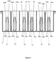
- FIG. 4 of the accompanying drawings there is shown a cross-sectional view of the battery container of figure 2 .
- One guide 6a, 8a, 106a, 108a, 206a, 208a of each pair of guides is arranged symmetrically with the other guide 6b, 8b, 106b, 108b, 206b, 208b of each pair of guides along an axis X1-6 which is orthogonal to the planar floor 4.
- a lower edge 82a, 82b, 84a, 84b, 86a, 86b, 88a, 88b, 90a, 90b, 92a, 92b of each guide of the pair of guides 6a, 6b, 8a, 8b, 106a, 106b, 108a, 108b, 206a, 206b, 208a, 208b does not extend to the planar floor 4.
- a ridge extends from the lower edge 82a, 82b, 84a, 84b, 86a, 86b, 88a, 88b, 90a, 90b, 92a, 92b of each guide of the pair of guides 6a, 6b, 8a, 8b, 106a, 106b, 108a, 108b, 206a, 206b, 208a, 208b to the planar floor 4, as will be described in more detail with reference to figure 6 .
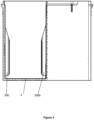
- Figure 5 shows a partial cut-away view of the battery container of figure 2 , viewed from an end of the container, wherein a lower edge 90b, 290b does not extend to the substantially planar floor 4.
- Figure 6 shows a perspective view of the embodiment shown in figure 2 , and more clearly shows the ridges 300a, 300b.
- the ridges 300a, 300b extend from the planar floor 4 to the portion of the lower end or edge 302a, 302b of each guide the pair of guides 6a, 6b that does not extend the planar floor 4.
- the ridges 300a, 300b provide structural integrity and/or serve to stiffen the guide.
- a force applied to the guides for example a force exerted upon the guides by insertion of a battery into the battery container, being more evenly distributed in the sidewall of the container. Further, such a force is also guided towards the floor of the container. Thus the force is distributed over a larger area than would be if the ridges were not present.
- such ridges 300a, 300b also increase an overall stiffness of the sidewalls of the container.
- ridges 300a, 300b improve the filling of the guide with material, because material may flow into a space within a mould defining the guides from a floor of the container, wherein the floor of the container comprises injection points.
- Figures 7 and 8 show a further a further plan view of the embodiment shown in figure 2 and a magnified portion of the further plan view of figure 7 respectively.
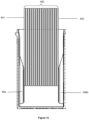
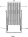
- Figure 9 shows a cross-sectional view of the first embodiment of the present invention, with plates 400 inserted.
- figure 9 shows 18 plates, one of skill in the art would recognise that a lesser or greater quantity of plates may be present.
- the dimensions of the plates relative to the container are provided for example purposes only.
- the guides 90b, 290b are in contact with an outer surface 401, 402 of the outmost plates.
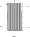
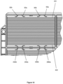
- Figure 15 shows a plan view of the embodiment of figure 9 .
- Figures 10 and 11 show the embodiment of figure 9 , with the plates 400 at different stages of insertion/removal.
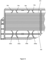
- Figure 12 shows a cross-sectional view of the first embodiment of the present invention, with plates 500 inserted. Similarly, although figure 12 shows 21 plates, one of skill in the art would recognise that a lesser or greater quantity of plates may be present.
- the guides 92b, 292b are in contact with an outer surface 501, 502 of the outmost plates. Each guide of the pair of guides 92b, 292b has undergone elastic deformation upon insertion of the plates 500.
- Figure 16 shows a plan view of embodiment of figure 12 .
- FIG 13 shows an exemplary embodiment of the present invention, wherein the plates 500 are partially inserted into the container. At least a portion of each guide 90b, 290b has undergone elastic deformation to accommodate the plates within the container.
- each guide 300a, 300b is adapted to deform such that the deformation is substantially uniform along a full length of the guide.
- Figure 17 shows a photo of the process of compression testing the guides 411a, 411b, 412a, 412b according to an exemplary embodiment of the present invention
- figure 18 shows the data resultant from the compression test shown.
- the label "Old Flexrib” corresponds to 'standard' guides that are known in the art, wherein the guides are substantially straight and do not comprise at least one curved portion and a lower edge of each guide does extend to the planar floor.
- the label "New FlexRib” corresponds to the present invention.
- the features of the guides interact synergistically to result in a guide that is more flexible and exhibits a greater degree or amount of flexing and/or deformation than a comparable guide without at least one curved portion over a defined ranges of applied forces.
- a comparable guide without the at least one curved portion and/or wherein a lower edge of each guide of each pair of guides does extend to the planar floor may require application of forces in the region of 300 to 600N to deform by approximately 2 to 8mm towards the planar floor.
- the present invention results in a knee in the force versus distance curve.
- the effect of this knee is that a force required to deform two pairs of guides by approximately 10mm towards the planar floor is in the region of 2000N.
- a comparable arrangement of guides without the at least one curved portion and/or wherein a lower edge of each guide of each pair of guides does extend to the planar floor requires application of considerably greater forces, such as forces in excess of 5000N, to achieve a similar degree of deformation.
- the provision of at least one curved portion on each guide of the pair of guides permits a tighter packing of plates, cells, cell elements or the likes into the container, without requiring undue forces to be applied.
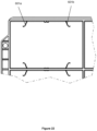
- each compartment comprises a single pair of guides 501a, 501b on each sidewall/partition of a pair of opposing sidewalls/partitions.
- the guides 501a, 501b are adapted such that each guide of the pair of guides 501a, 501b is adapted to curve towards the other guide of the pair of guides 501a, 501b.
- the pair of guides 501a, 501b is adapted such that, as the guides flex or deform upon insertion of a battery or the likes, the points of contact between the pair of guides 501a, 501b and the battery or the likes will tend towards one another.
- Figures 21 and 22 show a further embodiment of the present invention.
- This further embodiment comprises a single pair of guides 601a, 601b on each sidewall/partition of a pair of opposing sidewalls/partitions.
- a spacing between each guide 601a, 601b is greater than the spacing between each guide 6a, 6b, 8a, 8b in the embodiments shown in figure 1 .
- Figures 23 and 24 show a further embodiment of the present invention.
- This further embodiment comprises two pairs of guides 701a, 701b, 702a, 702b on each sidewall/partition of a pair of opposing sidewalls/partitions.
- the guides701a, 701b, 702a, 702b are adapted such that each guide of the pair of guides701a, 701b, 702a, 702b is adapted to curve towards the other guide of the pair of guides 701a, 701b, 702a, 702b.
- a spacing between each guide of a pair of guides 701a, 701b, 702a, 702b is greater than the spacing between each guide of a pair of guides 6a, 6b, 8a, 8b in the embodiments shown in figure 1 .
- guide 601a, 601b is greater than the spacing between each guide 6a, 6b, 8a, 8b in the embodiments shown in figure 1 .
- Figures 23 and 24 show a further embodiment of the present invention.
- This further embodiment comprises two pairs of guides 701a, 701b, 702a, 702b on each sidewall/partition of a pair of opposing sidewalls/partitions.
- the guides701a, 701b, 702a, 702b are adapted such that each guide of the pair of guides701a, 701b, 702a, 702b is adapted to curve towards the other guide of the pair of guides 701a, 701b, 702a, 702b.
- a spacing between each guide of a pair of guides 701a, 701b, 702a, 702b is greater than the spacing between each guide of a pair of guides 6a, 6b, 8a, 8b in the embodiments shown in figure 1 .
Landscapes
- Chemical & Material Sciences (AREA)
- Chemical Kinetics & Catalysis (AREA)
- Electrochemistry (AREA)
- General Chemical & Material Sciences (AREA)
- Engineering & Computer Science (AREA)
- Manufacturing & Machinery (AREA)
- Battery Mounting, Suspending (AREA)
Applications Claiming Priority (2)
| Application Number | Priority Date | Filing Date | Title |
|---|---|---|---|
| LU100178A LU100178B1 (en) | 2017-04-28 | 2017-04-28 | Battery container |
| PCT/EP2018/060952 WO2018197700A1 (en) | 2017-04-28 | 2018-04-27 | Battery container |
Publications (3)
| Publication Number | Publication Date |
|---|---|
| EP3616246A1 EP3616246A1 (en) | 2020-03-04 |
| EP3616246C0 EP3616246C0 (en) | 2024-10-09 |
| EP3616246B1 true EP3616246B1 (en) | 2024-10-09 |
Family
ID=59009746
Family Applications (1)
| Application Number | Title | Priority Date | Filing Date |
|---|---|---|---|
| EP18726928.7A Active EP3616246B1 (en) | 2017-04-28 | 2018-04-27 | Battery container |
Country Status (4)
| Country | Link |
|---|---|
| EP (1) | EP3616246B1 (pl) |
| LU (1) | LU100178B1 (pl) |
| PL (1) | PL3616246T3 (pl) |
| WO (1) | WO2018197700A1 (pl) |
Families Citing this family (1)
| Publication number | Priority date | Publication date | Assignee | Title |
|---|---|---|---|---|
| JP2025006252A (ja) * | 2023-06-29 | 2025-01-17 | トヨタ自動車株式会社 | 蓄電モジュール |
Family Cites Families (5)
| Publication number | Priority date | Publication date | Assignee | Title |
|---|---|---|---|---|
| US6376126B1 (en) * | 1999-10-13 | 2002-04-23 | Johnson Controls Technology Company | Composite battery container with integral flexible ribs |
| ITVI20020185A1 (it) * | 2002-08-14 | 2002-11-12 | Franco Stocchiero | Contenitore perfezionato per accumulatori elettrici |
| ITMI20031751A1 (it) * | 2003-09-11 | 2005-03-12 | Accuma Spa | Contenitore di batteria di accumulatori con sistema di |
| DE102007030652B3 (de) * | 2007-07-02 | 2008-11-13 | Varta Automotive Systems Gmbh | Prismatischer Akkumulator und Verfahren zum Herstellen eines primatischen Akkumulators |
| ITVI20120200A1 (it) * | 2012-08-03 | 2014-02-04 | Biasin S R L | Contenitore per piastre di un accumulatore elettrico |
-
2017
- 2017-04-28 LU LU100178A patent/LU100178B1/en active IP Right Grant
-
2018
- 2018-04-27 PL PL18726928.7T patent/PL3616246T3/pl unknown
- 2018-04-27 WO PCT/EP2018/060952 patent/WO2018197700A1/en not_active Ceased
- 2018-04-27 EP EP18726928.7A patent/EP3616246B1/en active Active
Also Published As
| Publication number | Publication date |
|---|---|
| LU100178B1 (en) | 2018-10-30 |
| EP3616246C0 (en) | 2024-10-09 |
| EP3616246A1 (en) | 2020-03-04 |
| PL3616246T3 (pl) | 2024-12-09 |
| WO2018197700A1 (en) | 2018-11-01 |
Similar Documents
| Publication | Publication Date | Title |
|---|---|---|
| US6376126B1 (en) | Composite battery container with integral flexible ribs | |
| JP7313975B2 (ja) | 基板収納容器 | |
| US20230216147A1 (en) | Battery pack | |
| US20230282919A1 (en) | Battery module having structure capable of absorbing cell swelling, and battery pack and vehicle comprising same | |
| US7816028B2 (en) | Accumulator battery container with plate insertion system, and plate inserting method | |
| CN112005399A (zh) | 电池模块 | |
| US9853257B2 (en) | Battery tray and battery container including the same | |
| KR102404261B1 (ko) | 전지 이송용 트레이 | |
| CN110476269B (zh) | 用于容纳多个二次电池单元的盖组件和包括其的电池模块 | |
| JPH1173932A (ja) | 電気化学式電池列の組み立て装置 | |
| EP3616246B1 (en) | Battery container | |
| US12469854B2 (en) | Apparatus accommodating copper foil | |
| EP4306293B1 (en) | Protrusion tray manufactured by vacuum forming | |
| US12212280B2 (en) | Multifunction spacer-wire clips for solar panels and related methods | |
| JP2002343320A (ja) | 収納ケース | |
| US7981493B2 (en) | Packing buffer member | |
| JP4101145B2 (ja) | 容器における仕切板の保持構造 | |
| TW202205727A (zh) | 具有複數個電池單元的電池模組以及製造該電池模組的方法 | |
| JP6801208B2 (ja) | 電池モジュール | |
| JP2011105373A (ja) | 周縁部にゴム部材を有する部品のための梱包材とそれを用いた梱包体および梱包方法 | |
| JP5468497B2 (ja) | 部品包装用トレイ及びそれを用いた梱包体 | |
| JP4693582B2 (ja) | ウエハ収納用紙製容器 | |
| US12473117B2 (en) | Composite tray | |
| EP4650847A1 (en) | Splice sleeve holders and trays including the same | |
| US20240025632A1 (en) | Storage container for tab lead, and combination of tab lead and storage container |
Legal Events
| Date | Code | Title | Description |
|---|---|---|---|
| STAA | Information on the status of an ep patent application or granted ep patent |
Free format text: STATUS: UNKNOWN |
|
| STAA | Information on the status of an ep patent application or granted ep patent |
Free format text: STATUS: THE INTERNATIONAL PUBLICATION HAS BEEN MADE |
|
| PUAI | Public reference made under article 153(3) epc to a published international application that has entered the european phase |
Free format text: ORIGINAL CODE: 0009012 |
|
| STAA | Information on the status of an ep patent application or granted ep patent |
Free format text: STATUS: REQUEST FOR EXAMINATION WAS MADE |
|
| 17P | Request for examination filed |
Effective date: 20191028 |
|
| AK | Designated contracting states |
Kind code of ref document: A1 Designated state(s): AL AT BE BG CH CY CZ DE DK EE ES FI FR GB GR HR HU IE IS IT LI LT LU LV MC MK MT NL NO PL PT RO RS SE SI SK SM TR |
|
| AX | Request for extension of the european patent |
Extension state: BA ME |
|
| DAV | Request for validation of the european patent (deleted) | ||
| DAX | Request for extension of the european patent (deleted) | ||
| STAA | Information on the status of an ep patent application or granted ep patent |
Free format text: STATUS: EXAMINATION IS IN PROGRESS |
|
| 17Q | First examination report despatched |
Effective date: 20220329 |
|
| REG | Reference to a national code |
Ref country code: DE Ref legal event code: R079 Ipc: H01M0010040000 Ref country code: DE Ref legal event code: R079 Ref document number: 602018075166 Country of ref document: DE Free format text: PREVIOUS MAIN CLASS: H01M0002020000 Ipc: H01M0010040000 |
|
| GRAP | Despatch of communication of intention to grant a patent |
Free format text: ORIGINAL CODE: EPIDOSNIGR1 |
|
| STAA | Information on the status of an ep patent application or granted ep patent |
Free format text: STATUS: GRANT OF PATENT IS INTENDED |
|
| RIC1 | Information provided on ipc code assigned before grant |
Ipc: H01M 50/112 20210101ALI20240325BHEP Ipc: B29C 45/26 20060101ALI20240325BHEP Ipc: H01M 10/16 20060101ALI20240325BHEP Ipc: H01M 10/06 20060101ALI20240325BHEP Ipc: H01M 10/04 20060101AFI20240325BHEP |
|
| INTG | Intention to grant announced |
Effective date: 20240429 |
|
| GRAS | Grant fee paid |
Free format text: ORIGINAL CODE: EPIDOSNIGR3 |
|
| GRAA | (expected) grant |
Free format text: ORIGINAL CODE: 0009210 |
|
| STAA | Information on the status of an ep patent application or granted ep patent |
Free format text: STATUS: THE PATENT HAS BEEN GRANTED |
|
| AK | Designated contracting states |
Kind code of ref document: B1 Designated state(s): AL AT BE BG CH CY CZ DE DK EE ES FI FR GB GR HR HU IE IS IT LI LT LU LV MC MK MT NL NO PL PT RO RS SE SI SK SM TR |
|
| REG | Reference to a national code |
Ref country code: CH Ref legal event code: EP |
|
| REG | Reference to a national code |
Ref country code: DE Ref legal event code: R096 Ref document number: 602018075166 Country of ref document: DE |
|
| REG | Reference to a national code |
Ref country code: IE Ref legal event code: FG4D |
|
| U01 | Request for unitary effect filed |
Effective date: 20241031 |
|
| U07 | Unitary effect registered |
Designated state(s): AT BE BG DE DK EE FI FR IT LT LU LV MT NL PT RO SE SI Effective date: 20241112 |
|
| REG | Reference to a national code |
Ref country code: GR Ref legal event code: EP Ref document number: 20240402949 Country of ref document: GR Effective date: 20250211 |
|
| PG25 | Lapsed in a contracting state [announced via postgrant information from national office to epo] |
Ref country code: HR Free format text: LAPSE BECAUSE OF FAILURE TO SUBMIT A TRANSLATION OF THE DESCRIPTION OR TO PAY THE FEE WITHIN THE PRESCRIBED TIME-LIMIT Effective date: 20241009 Ref country code: IS Free format text: LAPSE BECAUSE OF FAILURE TO SUBMIT A TRANSLATION OF THE DESCRIPTION OR TO PAY THE FEE WITHIN THE PRESCRIBED TIME-LIMIT Effective date: 20250209 |
|
| PG25 | Lapsed in a contracting state [announced via postgrant information from national office to epo] |
Ref country code: ES Free format text: LAPSE BECAUSE OF FAILURE TO SUBMIT A TRANSLATION OF THE DESCRIPTION OR TO PAY THE FEE WITHIN THE PRESCRIBED TIME-LIMIT Effective date: 20241009 |
|
| PG25 | Lapsed in a contracting state [announced via postgrant information from national office to epo] |
Ref country code: NO Free format text: LAPSE BECAUSE OF FAILURE TO SUBMIT A TRANSLATION OF THE DESCRIPTION OR TO PAY THE FEE WITHIN THE PRESCRIBED TIME-LIMIT Effective date: 20250109 |
|
| PGFP | Annual fee paid to national office [announced via postgrant information from national office to epo] |
Ref country code: GR Payment date: 20250318 Year of fee payment: 8 |
|
| PGFP | Annual fee paid to national office [announced via postgrant information from national office to epo] |
Ref country code: PL Payment date: 20250320 Year of fee payment: 8 |
|
| PG25 | Lapsed in a contracting state [announced via postgrant information from national office to epo] |
Ref country code: RS Free format text: LAPSE BECAUSE OF FAILURE TO SUBMIT A TRANSLATION OF THE DESCRIPTION OR TO PAY THE FEE WITHIN THE PRESCRIBED TIME-LIMIT Effective date: 20250109 |
|
| U20 | Renewal fee for the european patent with unitary effect paid |
Year of fee payment: 8 Effective date: 20250325 |
|
| U1N | Appointed representative for the unitary patent procedure changed after the registration of the unitary effect |
Representative=s name: NICOLLE, OLIVIER; LU |
|
| PG25 | Lapsed in a contracting state [announced via postgrant information from national office to epo] |
Ref country code: SM Free format text: LAPSE BECAUSE OF FAILURE TO SUBMIT A TRANSLATION OF THE DESCRIPTION OR TO PAY THE FEE WITHIN THE PRESCRIBED TIME-LIMIT Effective date: 20241009 |
|
| U1N | Appointed representative for the unitary patent procedure changed after the registration of the unitary effect |
Representative=s name: BONCEA, OANA-LAURA; LU |
|
| PG25 | Lapsed in a contracting state [announced via postgrant information from national office to epo] |
Ref country code: SK Free format text: LAPSE BECAUSE OF FAILURE TO SUBMIT A TRANSLATION OF THE DESCRIPTION OR TO PAY THE FEE WITHIN THE PRESCRIBED TIME-LIMIT Effective date: 20241009 |
|
| PGFP | Annual fee paid to national office [announced via postgrant information from national office to epo] |
Ref country code: CZ Payment date: 20250423 Year of fee payment: 8 |
|
| PLBE | No opposition filed within time limit |
Free format text: ORIGINAL CODE: 0009261 |
|
| STAA | Information on the status of an ep patent application or granted ep patent |
Free format text: STATUS: NO OPPOSITION FILED WITHIN TIME LIMIT |
|
| 26N | No opposition filed |
Effective date: 20250710 |
|
| REG | Reference to a national code |
Ref country code: CH Ref legal event code: H13 Free format text: ST27 STATUS EVENT CODE: U-0-0-H10-H13 (AS PROVIDED BY THE NATIONAL OFFICE) Effective date: 20251125 |
|
| PG25 | Lapsed in a contracting state [announced via postgrant information from national office to epo] |
Ref country code: MC Free format text: LAPSE BECAUSE OF FAILURE TO SUBMIT A TRANSLATION OF THE DESCRIPTION OR TO PAY THE FEE WITHIN THE PRESCRIBED TIME-LIMIT Effective date: 20241009 |
|
| GBPC | Gb: european patent ceased through non-payment of renewal fee |
Effective date: 20250427 |
|
| PG25 | Lapsed in a contracting state [announced via postgrant information from national office to epo] |
Ref country code: GB Free format text: LAPSE BECAUSE OF NON-PAYMENT OF DUE FEES Effective date: 20250427 |
|
| PG25 | Lapsed in a contracting state [announced via postgrant information from national office to epo] |
Ref country code: CH Free format text: LAPSE BECAUSE OF NON-PAYMENT OF DUE FEES Effective date: 20250430 |
|
| PG25 | Lapsed in a contracting state [announced via postgrant information from national office to epo] |
Ref country code: IE Free format text: LAPSE BECAUSE OF NON-PAYMENT OF DUE FEES Effective date: 20250427 |