EP3615369B1 - Sichtteil, insbesondere für ein bedienelement in einem kraftfahrzeug - Google Patents
Sichtteil, insbesondere für ein bedienelement in einem kraftfahrzeug Download PDFInfo
- Publication number
- EP3615369B1 EP3615369B1 EP18769041.7A EP18769041A EP3615369B1 EP 3615369 B1 EP3615369 B1 EP 3615369B1 EP 18769041 A EP18769041 A EP 18769041A EP 3615369 B1 EP3615369 B1 EP 3615369B1
- Authority
- EP
- European Patent Office
- Prior art keywords
- film
- substrate
- edge
- visible part
- visible
- Prior art date
- Legal status (The legal status is an assumption and is not a legal conclusion. Google has not performed a legal analysis and makes no representation as to the accuracy of the status listed.)
- Active
Links
Images

Classifications
-
- B—PERFORMING OPERATIONS; TRANSPORTING
- B60—VEHICLES IN GENERAL
- B60K—ARRANGEMENT OR MOUNTING OF PROPULSION UNITS OR OF TRANSMISSIONS IN VEHICLES; ARRANGEMENT OR MOUNTING OF PLURAL DIVERSE PRIME-MOVERS IN VEHICLES; AUXILIARY DRIVES FOR VEHICLES; INSTRUMENTATION OR DASHBOARDS FOR VEHICLES; ARRANGEMENTS IN CONNECTION WITH COOLING, AIR INTAKE, GAS EXHAUST OR FUEL SUPPLY OF PROPULSION UNITS IN VEHICLES
- B60K35/00—Instruments specially adapted for vehicles; Arrangement of instruments in or on vehicles
- B60K35/50—Instruments characterised by their means of attachment to or integration in the vehicle
-
- B—PERFORMING OPERATIONS; TRANSPORTING
- B60—VEHICLES IN GENERAL
- B60K—ARRANGEMENT OR MOUNTING OF PROPULSION UNITS OR OF TRANSMISSIONS IN VEHICLES; ARRANGEMENT OR MOUNTING OF PLURAL DIVERSE PRIME-MOVERS IN VEHICLES; AUXILIARY DRIVES FOR VEHICLES; INSTRUMENTATION OR DASHBOARDS FOR VEHICLES; ARRANGEMENTS IN CONNECTION WITH COOLING, AIR INTAKE, GAS EXHAUST OR FUEL SUPPLY OF PROPULSION UNITS IN VEHICLES
- B60K35/00—Instruments specially adapted for vehicles; Arrangement of instruments in or on vehicles
- B60K35/10—Input arrangements, i.e. from user to vehicle, associated with vehicle functions or specially adapted therefor
-
- B—PERFORMING OPERATIONS; TRANSPORTING
- B60—VEHICLES IN GENERAL
- B60K—ARRANGEMENT OR MOUNTING OF PROPULSION UNITS OR OF TRANSMISSIONS IN VEHICLES; ARRANGEMENT OR MOUNTING OF PLURAL DIVERSE PRIME-MOVERS IN VEHICLES; AUXILIARY DRIVES FOR VEHICLES; INSTRUMENTATION OR DASHBOARDS FOR VEHICLES; ARRANGEMENTS IN CONNECTION WITH COOLING, AIR INTAKE, GAS EXHAUST OR FUEL SUPPLY OF PROPULSION UNITS IN VEHICLES
- B60K35/00—Instruments specially adapted for vehicles; Arrangement of instruments in or on vehicles
- B60K35/20—Output arrangements, i.e. from vehicle to user, associated with vehicle functions or specially adapted therefor
- B60K35/21—Output arrangements, i.e. from vehicle to user, associated with vehicle functions or specially adapted therefor using visual output, e.g. blinking lights or matrix displays
- B60K35/22—Display screens
-
- B—PERFORMING OPERATIONS; TRANSPORTING
- B60—VEHICLES IN GENERAL
- B60R—VEHICLES, VEHICLE FITTINGS, OR VEHICLE PARTS, NOT OTHERWISE PROVIDED FOR
- B60R13/00—Elements for body-finishing, identifying, or decorating; Arrangements or adaptations for advertising purposes
- B60R13/02—Internal Trim mouldings ; Internal Ledges; Wall liners for passenger compartments; Roof liners
-
- B—PERFORMING OPERATIONS; TRANSPORTING
- B60—VEHICLES IN GENERAL
- B60K—ARRANGEMENT OR MOUNTING OF PROPULSION UNITS OR OF TRANSMISSIONS IN VEHICLES; ARRANGEMENT OR MOUNTING OF PLURAL DIVERSE PRIME-MOVERS IN VEHICLES; AUXILIARY DRIVES FOR VEHICLES; INSTRUMENTATION OR DASHBOARDS FOR VEHICLES; ARRANGEMENTS IN CONNECTION WITH COOLING, AIR INTAKE, GAS EXHAUST OR FUEL SUPPLY OF PROPULSION UNITS IN VEHICLES
- B60K2360/00—Indexing scheme associated with groups B60K35/00 or B60K37/00 relating to details of instruments or dashboards
- B60K2360/20—Optical features of instruments
- B60K2360/27—Optical features of instruments using semi-transparent optical elements
-
- B—PERFORMING OPERATIONS; TRANSPORTING
- B60—VEHICLES IN GENERAL
- B60R—VEHICLES, VEHICLE FITTINGS, OR VEHICLE PARTS, NOT OTHERWISE PROVIDED FOR
- B60R13/00—Elements for body-finishing, identifying, or decorating; Arrangements or adaptations for advertising purposes
- B60R13/02—Internal Trim mouldings ; Internal Ledges; Wall liners for passenger compartments; Roof liners
- B60R2013/0287—Internal Trim mouldings ; Internal Ledges; Wall liners for passenger compartments; Roof liners integrating other functions or accessories
Definitions
- the invention relates to a visible part, in particular a symbol-carrying visible part, in particular as a component for an operating element for control units and units in motor vehicles.
- a visible part in particular a symbol-carrying visible part, in particular as a component for an operating element for control units and units in motor vehicles.
- a large number of operating functions have to be set in motor vehicles today.
- a visually appealing design is desired, but at the same time durability of the components is required.
- the visible visible parts and even more so the visible parts that are regularly touched, for example the input parts of operating elements are subject to severe stresses and strongly fluctuating temperature influences, so that high demands are placed on the mechanical stability of the visible parts.
- These visible parts are regularly manufactured using a special shaping process known as Film Insert Molding (FIM). This means that complex-shaped plastic components that are equipped with a decorated or functional foil can be produced in just one operation.
- FIM Film Insert Molding
- thermoplastic film usually decorated on the back by printing
- a plastic film is formed, trimmed and the resulting preform is placed in an injection mold and back-injected with a thermoplastic.
- the process also commonly known as “foil back injection”
- the decorated foil is responsible for the appearance of the component.
- the surface impression gloss, structured, matt
- the deep gloss can be controlled via them.
- the part decor can be changed quickly without stopping production by using differently printed foils from shot to shot.
- Other properties such as high media or UV resistance, scratch and abrasion resistance, electrical conductivity or soft touch can be achieved with special composite or coated films.
- the film usually extends over the entire surface of the substrate and forms the visible surface alone, i.e. the surface facing the operator, of the visible part.
- the film is thus cut to be congruent with respect to the surface of the substrate and the edge of the substrate delimiting the surface coincides with the edges of the film.
- This places high demands on the precise positioning of the film relative to the substrate.
- the symbols could be cut out of the printed foil exactly following the contour of the symbol.
- this complicates the positioning of the foil-shaped symbols relative to the substrate, particularly in the shaping tool for foil back-injection molding, and places high demands on the cutting of the foil, not only when the symbols cannot be represented by closed surfaces. There is therefore a need for a way of being able to dispense with the cutting of the film with precise edges in relation to the surface of the substrate, without optical impairment occurring.
- the invention is based on the object of developing a visible part, in particular for motor vehicles, which is comparatively simple and inexpensive to produce without impairing the visual appearance.
- This object is achieved by a visible part according to claim 1.
- An equally advantageous manufacturing method is the subject of the independent claim.
- Advantageous configurations can be found in the dependent claims. It should be pointed out that the features listed individually in the patent claims can be combined with one another in any technologically meaningful manner and show further refinements of the invention. The description, in particular in connection with the figures, additionally characterizes and specifies the invention.
- the invention relates to a visible part for a motor vehicle.
- the visible part has a substrate.
- the substrate defines a surface facing the viewer.
- the visible part also has a transparent or translucent film which is applied to the surface over the entire surface but only partially covering the surface, forming a peripheral edge, so that the substrate and film together define a visible surface.
- the edge of the film falls at no point with the edge of the surface of the substrate together. For example, a distance of a few millimeters is provided between the edge of the foil and the edge of the surface of the substrate.
- the film has a first screen printing which extends along the edge and adjoins the edge.
- the screen printing has an area arranged adjacent to the edge, in which the density of the screen printing decreases from the inside to the outside, preferably steadily decreasing from the inside to the outside. In other words: the light transmission increases from the outside to the inside.
- raster printing is provided on the film.
- the density of the screen printing varies in the outer edge area towards the edge, namely decreases steadily towards the edge, as a result of which the light transmission increases towards the edge.
- an optical transition area is created in comparison to the film that is unprinted at the edge, through which the actual sharp transition defined by the edge optically recedes into the background and almost disappears.
- film material can now be saved without impairing the optical attractiveness of the visible part.
- a separate shaping step for the film can be omitted in the method according to the invention.
- shrinkage processes of the film can be neglected, for example during its shaping in a shaping step.
- the film is printed over the entire surface in one color with screen printing and has the screen printing with a varying screen tone value, ie one that decreases from the inside to the outside, at least in the edge area of a few millimeters adjacent to the edge of the screen.
- a varying screen tone value ie one that decreases from the inside to the outside, at least in the edge area of a few millimeters adjacent to the edge of the screen.
- the width of the area in which the screen printing has a varying screen tone value is 2.0 to 6.0 mm.
- the screen printing is applied to the film, for example by screen printing, digital or offset printing, in particular to the surface of the film facing the substrate, i.e. the surface of the film facing away from the visible surface.
- the film is, for example, a polycarbonate film, a blend film made from polycarbonate and polyester or an extruded film based on a polycarbonate/PBT (polybutylene terephthalate) blend, an extruded film made from ABS (acrylonitrile butadiene styrene polymer) or the like.
- the thickness of the foil is, for example, 100 to 500 ⁇ m.
- the film preferably has further printing, which is arranged, for example, away from the edge and represents a symbol.
- the screen printing extending along the edge has a color tone that corresponds to that of the material of the substrate.
- the shade is preferably black.
- a corresponding hue is, for example, an identical color coordinate in the same color space, such as CYMK or RGB, or an identical color pattern from the color catalogs such as RAL or Pantone. Saturation and brightness can vary.
- the substrate is made of a plastic, such as a thermoplastic.
- the halftone value is preferably in the range from 50% to 80%, more preferably in the range from 60% to 70%, even more preferably in the range from 62% to 67%.
- a layer of transparent or translucent material is provided adjacent the face of the film and substrate to protect the film and substrate.
- the visible part is preferably produced by in-moulding the film with the material of the substrate in a shaping process such as film insert molding.
- the film is also front sprayed with a further, transparent or translucent material in order to form the aforementioned layer, which is arranged adjacent to the visible surface of the film and substrate.
- the visible surface defined by the film, in particular by the substrate and the film, is preferably not flat.
- the invention relates to the use of the visible part in one of the previously described embodiments in a motor vehicle, in particular as part of a control element in a motor vehicle.
- a control element in a motor vehicle.
- it is an input part of a control, i.e. a part of a control intended for actuating touch by an operator's hand or finger.
- the invention also relates to a method for producing a visible part, which defines a visible surface and has a film and a substrate.
- the procedure has the following steps.
- a deployment step a slide is deployed.
- the film is, for example, a polycarbonate film, a blend film made from polycarbonate and polyester or an extruded film based on a polycarbonate/PBT (polybutylene terephthalate) blend, an extruded film made from ABS (acrylonitrile butadiene styrene polymer) or the like.
- the thickness of the foil is, for example, 100 to 500 ⁇ m.
- the film is printed in one or more screen printing steps with at least one screen printing to form at least one printed layer.
- the film is preferably only printed on one side.
- the film is formed by thermoforming, hydroforming, mechanical forming or high-pressure forming (HPF).
- the film is trimmed by manual trimming, such as punching, or by steel strip cutting, or by a full-cut tool, or by water jet or laser cutting,
- the film is then placed in a shaping tool in such a way that the film comes to rest over the entire surface in a subsequent back-injection step on a surface of the substrate, with at least one of the printed layers facing the substrate.
- the film is back-injected with a material of the substrate to form the visible part, with the film only partially covering the surface and forming a peripheral edge on the substrate, so that the substrate and the film together form the visible surface and the screen printing extending along the edge and being located adjacent to the edge.
- the screen tonal value of the screen printing varies in the outer edge area towards the edge, namely decreases towards the edge of the film.
- the visible part is then removed from the shaping tool.
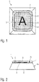
- the visible part 1 has a transparent film 3 which is applied to a partial surface 7b of the surface 7a, 7b of a substrate 2 made of a thermoplastic.
- the film 3 covers the substrate 2 only partially, so that the partial surface 7a of the substrate 2 that is not covered by the film 3 and protrudes beyond the edge 4 of the film 3 and the film 3 together form the visible surface of the visible part 1 .
- the film 3 is therefore smaller than the visible surface of the visible part 1 and its edge 4 lies within the visible surface.
- the film 3 serves as a carrier for a symbol 5, which is printed on the back, ie the side of the film 3 facing the substrate 2, such as figure 2 shows is upset.
- the rear side of the film 2 is printed with a raster print 8, which extends along the edge 4 and adjacent to it.
- the raster print 8 made of opaque material, such as paint, has a color, such as black, which corresponds to that of the substrate.
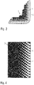
- the screen printing 8 is applied over the entire surface of the film 3, but has an area 6 arranged adjacent to the edge 4, in which the density of the screen printing 8 and thus the transparency of the film 3 varies. this is in figure 3 schematically illustrated.
- the density of the grid printing 8 in the area 6 decreases from the inside to the outside. In other words, the light transmission increases in the area 6 towards the edge 4 .
- the halftone value of halftone printing 8 is 65%.
- the grid printing 8 is achieved by printing dots of opaque material on the transparent film 3, with the density and thus the light transmission being adjusted in regions by varying the dot size and the spacing of the dots.
- An alternative embodiment is in figure 4 shown, in which a raster printing 8 made of opaque material, such as paint, is selected in which the transparent dots remain outside the printed area, the diameter of which increases toward the edge 4 .
- the grid printing 8, in particular with varying density, creates an optical transition area in comparison to the unprinted film 3 at the edge 4, through which the actual sharp transition between the film 3 and the substrate 2 defined by the edge 4 optically fades into the background and almost disappears.
- figure 5 shows a further embodiment of the visible part 1. This shows in contrast to the embodiment of FIG figure 1 furthermore a layer 9 of transparent or translucent material, which is arranged adjacent to the viewing surface formed by the film 3 and the substrate 2 and which defines the surface of the viewing part 1 which faces the operator.
- the layer 9 is formed by overmoulding the film 3 with a transparent material.
Landscapes
- Engineering & Computer Science (AREA)
- Mechanical Engineering (AREA)
- Chemical & Material Sciences (AREA)
- Combustion & Propulsion (AREA)
- Transportation (AREA)
- Injection Moulding Of Plastics Or The Like (AREA)
- Laminated Bodies (AREA)
Description
- Die Erfindung betrifft ein Sichtteil, insbesondere ein symboltragendes Sichtteil insbesondere als Komponente für ein Bedienelement für Steuergeräte und Aggregate in Kraftfahrzeugen. In Kraftfahrzeugen sind heutzutage eine Vielzahl von Bedienfunktionen einzustellen. Dabei ist eine optische ansprechende Gestaltung erwünscht und gleichzeitig aber auch eine Haltbarkeit der Komponenten erforderlich. Insbesondere die sichtbaren Sichtteile und noch mehr die regelmäßig einer Berührung ausgesetzten Sichtteile, beispielsweise die Eingabeteile von Bedienelementen unterliegen starken Beanspruchungen und stark schwankenden Temperatureinflüssen, so dass hohe Anforderungen an die mechanische Stabilität der Sichtteile gestellt sind. Diese Sichtteile werden regelmäßig in einem speziellen formgebenden Verfahren, dem sogenannten Film Insert Molding (FIM) hergestellt. Damit lassen sich in nur einem Arbeitsgang komplex geformte Kunststoffbauteile herstellen, die mit einer dekorierten oder funktionalen Folie ausgestattet sind. Dazu wird eine meist durch Bedrucken rückseitig dekorierte Kunststoff-Folie umgeformt, beschnitten und der resultierende Vorformling in ein Spritzgießwerkzeug gelegt und mit einem Thermoplasten hinterspritzt. Das allgemein auch "Folienhinterspritzen" genannte Verfahren macht also separate Prozessschritte zur nachträglichen Dekorierung und Funktionalisierung von Bauteilen wie etwa ein Beschichten oder Lackieren überflüssig. Dadurch ergeben sich erhebliche Einsparungen in punkto Fertigungskosten, Zeit und Anlageninvestitionen sowie eine große Flexibilität.
- Die dekorierte Folie ist für das Aussehen des Bauteils verantwortlich. Über sie können neben dem Dekor (einfarbig, mehrfarbig, Metallic-Effekte, integrierte Symbole, Durchlichttechnik) auch der Oberflächeneindruck (glänzend, strukturiert, matt) und der Tiefenglanz gesteuert werden. Wie bei kaum einem anderen Verfahren kann das Teiledekor schnell ohne Produktionsstopp gewechselt werden, indem man von Schuss zu Schuss unterschiedlich bedruckte Folien einsetzt. Weitere Eigenschaften wie eine hohe Medien- oder UV-Beständigkeit, Kratz- und Abriebfestigkeit, eine elektrische Leitfähigkeit oder Softtouch können mit speziellen Verbund- oder beschichteten Folien verwirklicht werden.
- Aus optischen Gründen erstreckt sich dabei die Folie in der Regel vollflächig über die gesamte Oberfläche des Substrats und bildet alleine die Sichtfläche, d.h. die dem Bediener zugewandte Oberfläche, des Sichtteils aus. Somit ist die Folie bezogen auf die Oberfläche des Substrats deckungsgleich zugeschnitten und der die Oberfläche begrenzende Rand des Substrats fällt mit den Kanten der Folie zusammen. Dies stellt hohe Anforderungen an genaue Positionierung der Folie relativ zum Substrat. Alternativ könnten die Symbole aus der bedruckten Folie der Kontur des Symbols folgend exakt ausgeschnitten werden. Dies kompliziert aber die Positionierung der folienförmigen Symbole relativ zum Substrat, insbesondere im formgebenden Werkzeug für das Folienhinterspritzen und stellt hohe Anforderungen an den Zuschnitt der Folie, nicht nur wenn die Symbole nicht durch geschlossene Flächen darstellbar sind. Es besteht daher Bedarf nach einer Möglichkeit, auf den bezogen auf die Oberfläche des Substrats kantengenauen Zuschnitt der Folie verzichten zu können, ohne dass es zu einer optischen Beeinträchtigung kommt.
- Der Erfindung liegt die Aufgabe zu Grunde, ein Sichtteil insbesondere für Kraftfahrzeugen zu entwickeln, dass vergleichsweise einfach und preiswert herzustellen ist, ohne die optische Erscheinung zu beeinträchtigen. Diese Aufgabe wird durch ein Sichtteil gemäß Anspruch 1 gelöst. Ein gleichermaßen vorteilhaftes Herstellungsverfahren ist Gegenstand des nebengeordneten Anspruchs. Vorteilhafte Ausgestaltungen sind den Unteransprüchen zu entnehmen. Es ist darauf hinzuweisen, dass die in den Patentansprüchen einzeln aufgeführten Merkmale in beliebiger, technologisch sinnvoller Weise miteinander kombiniert werden können und weitere Ausgestaltungen der Erfindung aufzeigen. Die Beschreibung, insbesondere im Zusammenhang mit den Figuren, charakterisiert und spezifiziert die Erfindung zusätzlich.
- Die Erfindung betrifft ein Sichtteil für ein Kraftfahrzeug. Das Sichtteil weist ein Substrat auf. Das Substrat definiert eine dem Betrachter zugewandte Oberfläche. Das Sichtteil weist ferner eine transparente oder transluzente Folie auf, die auf der Oberfläche vollflächig aber die Oberfläche nur partiell überdeckend unter Ausbildung einer umlaufenden Kante aufgebracht ist, so dass Substrat und Folie gemeinsam eine Sichtfläche definieren. Erfindungsgemäß fällt die Kante der Folie an keiner Stelle mit dem Rand der Oberfläche des Substrats zusammen. Beispielsweise ist ein Abstand von einigen Millimetern zwischen der Kante der Folie und dem Rand der Oberfläche des Substrats vorgesehen. Zur optischen Verschleierung der Kanten der Folie weist die Folie eine erste, entlang der Kante sich erstreckende und an die Kante angrenzende Rasterbedruckung auf. Erfindungsgemäß weist die Rasterbedruckung einen angrenzend an die Kante angeordneten Bereich auf, in dem die Dichte der Rasterbedruckung von innen nach außen hin abnimmt, bevorzugt von innen nach außen stetig abnimmt. Anders ausgedrückt: die Lichtdurchlässigkeit nimmt von außen nach innen zu.
- Anders ausgedrückt zur Bereitstellung eines "verdeckten" Übergangs betreffend den Farbübergang von der Folie zu dem die Folie überragenden Bereich der Oberfläche des Substrats ist eine Rasterbedruckung auf der Folie vorgesehen. Zur besseren optischen Verschleierung des Kantenverlaufs der Folie variiert die Dichte der Rasterbedruckung im äußeren Kantenbereich hin zur Kante, nimmt nämlich hin zur Kante stetig ab, wodurch die Lichtdurchlässigkeit zur Kante hin ansteigt.
- Durch die Rasterbedruckung, insbesondere mit variierendem Rastertonwert, wird im Vergleich zur an der Kante unbedruckten Folie somit ein optischer Übergangsbereich geschaffen, durch den der eigentliche scharfe, durch die Kante definierte Übergang optisch in den Hintergrund tritt und nahezu verschwindet. Dadurch kann im Vergleich zur mit der Sichtfläche deckungsgleichen Auslegung der Folie Folienmaterial nunmehr eingespart werden, ohne die optische Attraktivität des Sichtteils zu beeinträchtigen. Ein separater Formgebungsschritt für die Folie kann bei dem erfindungsgemäßen Verfahren entfallen. Darüber hinaus können Schrumpfungsprozesse der Folie beispielsweise bei deren Formgebung in einem Formungsschritt vernachlässigt werden.
- Beispielsweise ist die Folie vollflächig einfarbig mit Rasterbedruckung bedruckt und weist zumindest im an die Kante der Folie angrenzenden Randbereich von einigen Millimetern die Rasterbedruckung mit variierendem, d.h. von innen nach außen abnehmendem Rastertonwert auf. Beispielsweise beträgt die Breite des Bereichs, in dem die Rasterbedruckung einen variierenden Rastertonwert aufweist, 2,0 bis 6,0 mm.
- Die Rasterbedruckung ist beispielsweise im Siebdruck, im Digital- oder Offsetdruck auf die Folie insbesondere auf die dem Substrat zugewandte, d.h. der Sichtfläche abgewandten Oberfläche der Folie aufgebracht.
- Bei der Folie handelt es sich beispielsweise um eine Polycarbonatfolie, eine Blendfolie aus Polycarbonat und Polyester oder eine Extrusionsfolie auf Basis eines Polycarbonat/PBT(Polybutylenterephthaiat)-Blends, eine Extrusionsfolie aus ABS (Polymerisat aus Acrylnitril-Butadien-Styrol) oder dergleichen. Die Dicke der Folie beträgt beispielsweise 100 bis 500 µm.
- Bevorzugt weist die Folie eine weitere Bedruckung auf, die beispielsweise entfernt der Kante angeordnet ist und ein Symbol darstellt.
- Erfindungsgemäß weist die entlang der Kante sich erstreckende Rasterbedruckung einen Farbton auf, der der des Materials des Substrats entspricht. Bevorzugt ist der Farbton schwarz. Als ein entsprechender Farbton wird beispielsweise eine identische Farbkoordinate im selben Farbraum, wie CYMK oder RGB, oder ein identisches Farbmuster aus den Farbkatalogen wie RAL oder Pantone verstanden. Dabei können Sättigung und Helligkeit abweichend ausfallen.
- Gemäß einer bevorzugten Ausgestaltung ist das Substrat aus einem Kunststoff, wie einem Thermoplast.
- Zur zahlenmäßigen Erfassung und Definition bestimmter flächenvariabler binärer Bildinformationen dient der Rastertonwert F in Prozent auf der Folie. Er gibt das Verhältnis einer bestimmten, mit Rasterpunkten bedeckten Fläche zur transparenten Folie an: unbedruckte Folie = 0%, Vollton = 100%. Beispiel: Bei einem Rastertonwert von 50% ist genau die Hälfte der Fläche (beispielsweise schachbrettartig) mit Rasterpunkten bedeckt, bei der anderen Hälfte ist die Folie unbedruckt d.h. transparent.
- Bevorzugt liegt der Rastertonwert bezogen auf die mit der Rasterbedruckung versehenen Folienfläche im Bereich von 50 % bis 80 %, bevorzugter im Bereich von 60 % bis 70 %, noch bevorzugter im Bereich von 62 % bis 67 %.
- Bevorzugt ist eine Schicht aus transparentem oder transluzentem Material vorgesehen, die angrenzend an die Sichtfläche von Folie und Substrat angeordnet ist, um die Folie und das Substrat zu schützen.
- Bevorzugt ist das Sichtteil durch Hinterspritzen der Folie mit dem Material des Substrats in einem formgebenden Verfahren, wie dem Film Insert Molding, hergestellt. In einer weiteren Ausgestaltung ist ferner ein Vorderspritzen der Folie mit einem weiteren, transparenten oder transluzenten Material vorgesehen, um die vorgenannte Schicht auszubilden, die angrenzend an die Sichtfläche von Folie und Substrat angeordnet ist.
- Bevorzugt ist die durch die Folie, insbesondere die durch das Substrat und die Folie, definierte Sichtfläche nicht eben ausgestaltet.
- Die Erfindung betrifft die Verwendung des Sichtteils in einer der zuvor beschriebenen Ausführungsformen in einem Kraftfahrzeug, insbesondere als Teil eines Bedienelements in einem Kraftfahrzeug. Beispielsweise handelt es sich um ein Eingabeteil eines Bedienelements, d.h. ein für die betätigende Berührung durch die Hand oder den Finger eines Bedieners bestimmtes Teil eines Bedienelements.
- Die Erfindung betrifft ferner ein Verfahren zur Herstellung eines Sichtteils, welches eine Sichtfläche definiert und eine Folie und ein Substrat aufweist. Das Verfahren weist folgende Schritte auf. In einem Bereitstellungsschritt wird eine Folie bereitgestellt. Bei der Folie handelt es sich beispielsweise um eine Polycarbonatfolie, eine Blendfolie aus Polycarbonat und Polyester oder eine Extrusionsfolie auf Basis eines Polycarbonat/PBT(Polybutylenterephthalat)-Blends, eine Extrusionsfolie aus ABS (Polymerisat aus Acrylnitril-Butadien-Styrol) oder dergleichen. Die Dicke der Folie beträgt beispielsweise 100 bis 500 µm.
- In einem Bedruckungsschritt erfolgt ein Bedrucken der Folie in einem oder mehreren Siebdruckschritten mit wenigstens einer Rasterbedruckung unter Ausbildung wenigstens einer Druckschicht. Bevorzugt wird die Folie lediglich einseitig bedruckt.
- In einem nachfolgenden, optionalen Verformungsschritt erfolgt ein Verformen der Folie durch Thermoformen, Hydroforming, mechanische Verformung oder Hochdruckverformung (HPF).
- In einem nachfolgenden Zuschnitt erfolgt ein Beschneiden der Folie durch manuelles Beschneiden, wie Stanzen, oder durch Bandstahlschnitt oder durch ein Vollschnittwerkzeug oder durch Wasserstrahl- oder Laserschneiden,
- Nachfolgend erfolgt ein Einlegen der Folie in ein formgebendes Werkzeug derart, dass die Folie in einem nachfolgenden Hinterspritzschritt auf einer Oberfläche des Substrats, mit wenigstens einer der Druckschichten zum Substrat gewandt, vollflächig zum Anliegen kommt.
- In dem nachfolgenden Hinterspritzschritt erfolgt ein Hinterspritzen der Folie mit einem Material des Substrats unter Ausbildung des Sichtteils, wobei die Folie die Oberfläche nur partiell überdeckend unter Ausbildung einer umlaufenden Kante auf das Substrat aufgebracht ist, so dass das Substrat und die Folie gemeinsam die Sichtfläche ausbilden und die Rasterbedruckung entlang der Kante sich erstreckend und angrenzend an die Kante angeordnet ist. Zur besseren optischen Verschleierung des Kantenverlaufs der Folie variiert der Rastertonwert der Rasterbedruckung im äußeren Kantenbereich hin zur Kante, nimmt nämlich hin zur Kante der Folie ab.
- Danach erfolgt die Entnahme des Sichtteils aus dem formgebenden Werkzeug.
- Durch die Rasterbedruckung, insbesondere mit variierendem Rastertonwert, wird im Vergleich zur an der Kante unbedruckten Folie somit ein optischer Übergangsbereich geschaffen, durch den der eigentliche Kantenübergang optisch in den Hintergrund tritt und nahezu verschwindet. Dadurch kann im Vergleich zur mit der Sichtfläche deckungsgleichen Auslegung der Folie bei dem erfindungsgemäßen Verfahren Folienmaterial eingespart werden, ohne die optische Attraktivität des Sichtteils zu beeinträchtigen. Darüber hinaus können Schrumpfungsprozesse der Folie beispielsweise bei deren Formgebung in einem Formungsschritt vernachlässigt werden.
- Die Erfindung wird anhand der nachfolgenden Figuren näher erläutert. Die Figuren sind dabei nur beispielhaft zu verstehen und stellen lediglich bevorzugte Ausführungsvarianten dar. Es zeigen:
- Figur 1
- eine Aufsicht auf eine erfindungsgemäße Ausführungsform des Sichtteils;
- Figur 2
- eine Schnittansicht durch die Ausführungsform der
Figur 1 ; - Figur 3
- eine Detailansicht der Folie 3 aus
Figur 1 ; - Figur 4
- eine Detailansicht einer alternativen Ausführungsform der Folie 3 aus
Figur 1 ; - Figur 5
- eine Schnittansicht durch eine weitere Ausführungsform des Sichtteils.
- Das erfindungsgemäße Sichtteil 1 weist eine transparente Folie 3, die auf einer Teiloberfläche 7b der Oberfläche 7a, 7b eines Substrat 2 aus einem Thermoplast aufgebracht ist. Dabei bedeckt die Folie 3 das Substrat 2 lediglich partiell, so dass die von der Folie 3 nicht bedeckte, über die Kante 4 der Folie 3 hinausragende Teiloberfläche 7a des Substrats 2 und die Folie 3 gemeinsam die Sichtfläche des Sichtteils 1 ausbilden. Die Folie 3 ist somit kleiner als die Sichtfläche des Sichtteils 1 und deren Kante 4 liegt innerhalb der Sichtfläche. Die Folie 3 dient als Träger für ein Symbol 5, das durch rückwärtige Bedruckung, d.h. der dem Substrat 2 zugewandten Seite der Folie 3, wie
Figur 2 zeigt, aufgebracht ist. Neben der Bedruckung mit dem Symbol 5 ist die rückwärtige Seite der Folie 2 mit einer Rasterbedruckung 8 bedruckt, die sich entlang der Kante 4 und angrenzend an diese erstreckt. Die Rasterbedruckung 8 aus opakem Material, wie Lack, weist einen Farbton, wie schwarz auf, die der des Substrats entspricht. Die Rasterbedruckung 8 ist im vorliegenden Fall vollflächig auf der Folie 3 aufgebracht, weist aber einen angrenzend an die Kante 4 angeordneten Bereich 6 auf, in der der die Dichte der Rasterbedruckung 8 und damit die Lichtdurchlässigkeit der Folie 3 variiert. Dies ist inFigur 3 schematisch veranschaulicht. So nimmt die Dichte der Rasterbedruckung 8 im Bereich 6 innen nach außen ab. Anders ausgedrückt, die Lichtdurchiässigkeit nimmt im Bereich 6 hin zur Kante 4 zu. Der Rastertonwert der Rasterbedruckung 8 beträgt 65%. Die Rasterbedruckung 8 wird durch eine Bedruckung mit Punkten aus opakem Material der transparenten Folie 3 erreicht, wobei die Dichte und damit die Lichtdurchlässigkeit durch Variation der Punktgröße und der Beabstandung der Punkte bereichsweise eingestellt wird. Eine alternative Ausführungsform ist inFigur 4 gezeigt, bei der eine Rasterbedruckung 8 aus opakem Material, wie Lack, gewählt ist, bei der transparente Punkte außerhalb des bedruckten Bereichs verbleiben, deren Durchmesser zur Kante 4 hin zu nehmen. Durch die Rasterbedruckung 8, insbesondere mit variierender Dichte, wird im Vergleich zur an der Kante 4 unbedruckten Folie 3 somit ein optischer Übergangsbereich geschaffen, durch den der eigentliche scharfe, durch die Kante 4 definierte Übergang zwischen Folie 3 und Substrat 2 optisch in den Hintergrund tritt und nahezu verschwindet. Ferner kann im Vergleich zu einer mit der Sichtfläche deckungsgleichen Auslegung der Folie 3 Folienmaterial eingespart werden, ohne die optische Attraktivität des Sichtteils 1 zu beeinträchtigen. Folie 3 und Substrat 2 sind kraftschlüssig durch sogenanntes Film Insert Molding, d.h. Hinterspritzen der Folie 3 mit dem Material des Substrats 2 in einem formgebenden Werkzeug verbunden.Figur 5 zeigt eine weitere Ausführungsform des Sichtteils 1. Dieses zeigt im Unterschied zur Ausführungsform derFigur 1 ferner eine Schicht 9 aus transparentem oder transluzentem Material, welche angrenzend an die von der Folie 3 und dem Substrat 2 ausgebildeten Sichtfläche angeordnet ist und weiche die dem Bediener zugewandte Oberfläche des Sichtteils 1 definiert. Die Schicht 9 wird durch Vorderspritzen der Folie 3 mit einem transparenten Material ausgebildet.
Claims (10)
- Sichtteil (1) mit einer Sichtfläche für ein Kraftfahrzeug, aufweisend:ein Substrat (2); welches eine Oberfläche (7a, 7b) definiert;eine transparente oder transluzente Folie (3), die auf der Oberfläche (7a, 7b) vollflächig aber die Oberfläche (7a, 7b) nur partiell überdeckend unter Ausbildung einer umlaufenden Kante (4) aufgebracht ist;wobei die Folie (3) eine entlang ihrer Kante (4) sich erstreckende, an die Kante (4) angrenzend angeordnete Rasterbedruckung (8) aufweist,wobei das Substrat (2) und die Folie (3) gemeinsam die Sichtfläche ausbilden und die Kante (4) der Folie (3) an keiner Stelle mit einem Rand der Oberfläche (7a, 7b) des Substrats (2) zusammenfällt; wobei die Rasterbedruckung (8) einen angrenzend an die Kante (4) angeordneten Bereich (6) aufweist, in dem die Dichte der Rasterbedruckung (8) von innen nach außen abnimmt und wobei die Rasterbedruckung (8) einen Farbton aufweist, der der des Substrats (2) entspricht.
- Sichtteil (1) nach dem vorhergehenden Anspruch, wobei die Folie (3) eine weitere Bedruckung (5) aufweist, die ein Symbol darstellt.
- Sichtteil (1) nach dem vorhergehenden Anspruch, wobei der Farbton schwarz ist.
- Sichtteil (1) nach einem der vorhergehenden Ansprüche, wobei die Folie (3) eine Polycarbonatfolie, eine Blendfolie aus Polycarbonat und Polyester oder eine Extrusionsfolie auf Basis eines Polycarbonat-/PBT-Blend oder eine Extrusionsfolie aus ABS ist.
- Sichtteil (1) nach einem der vorhergehenden Ansprüche, wobei das Substrat (2) aus einem Kunststoff, wie einem Thermoplast, ist.
- Sichtteil (1) nach einem der vorhergehenden Ansprüche, wobei der Rastertonwert der Rasterbedruckung (8) im Bereich 50 % bis 80 %, bevorzugt 60 % bis 70 %, noch bevorzugt 62 % bis 67 % beträgt.
- Sichtteil (1) nach einem der vorhergehenden Ansprüche, mit einer Schicht (9) aus transparentem oder transluzentem Material, die angrenzend an die Sichtfläche von Folie (3) und Substrat (2) angeordnet ist.
- Verwendung des Sichtteils (1) nach einem der vorhergehenden Ansprüche in einem Kraftfahrzeug, insbesondere als Teil eines Bedienelements in einem Kraftfahrzeug.
- Verfahren zur Herstellung eines Sichtteils (1) mit einer Sichtfläche, wobei das Sichtteil (1) eine Folie (3) und ein Substrat (2) aufweist, mit den Schritten:• Bereitstellen einer Folie (3);• Bedrucken der Folie (3) in einem oder mehreren Siebdruckschritten mit wenigstens einer Rasterbedruckung (8) unter Ausbildung wenigstens einer Druckschicht;• Optionales Verformen der Folie (3) durch Thermoformen, Hydroforming, mechanische Verformung oder Hochdruckverformung (HFP);• Beschneiden der Folie (3) durch manuelles Beschneiden, wie Stanzen, oder Bandstahlschnitt oder mittels Vollschnittwerkzeug oder mittels Wasserstrahl oder durch Laserschneiden;• Einlegen der Folie (3) in ein formgebendes Werkzeug derart, dass die Folie (3) in einem nachfolgenden Schritt des Hinterspritzens auf einer Oberfläche (7a, 7b) des Substrats (2) mit der Druckschicht zum Substrat (2) gewandt vollflächig zum Anliegen kommt;• Hinterspritzen der Folie (3) mit dem Material des Substrats (2) unter Ausbildung des Sichtteils (1); wobei die Folie (3) die Oberfläche (7a, 7b) des Substrats (2) nur partiell überdeckend unter Ausbildung einer umlaufenden Kante (4) auf das Substrat aufgebracht ist, und die Rasterbedruckung (8) entlang der Kante (4) sich erstreckend und angrenzend an die Kante (4) angeordnet ist;• Entnahme des Sichtteils (1) aus dem formgebenden Werkzeug, wobei das Substrat (2) und die Folie (3) gemeinsam die Sichtfläche ausbilden und die Kante (4) der Folie (3) an keiner Stelle mit einem Rand der Oberfläche (7a, 7b) des Substrats (2) zusammenfällt; wobei die Rasterbedruckung (8) einen angrenzend an die Kante (4) angeordneten Bereich (6) aufweist, in dem die Dichte der Rasterbedruckung (8) von innen nach außen abnimmt und wobei die Rasterbedruckung (8) einen Farbton aufweist, der der des Substrats (2) entspricht.
- Verfahren zur Herstellung eines Sichtteils (1) gemäß dem vorhergehenden Anspruch; mit einem Schritt des Vorderspritzens wenigstens der Folie (3) mit einem weiteren, transparenten oder transluzenten Material zur Ausbildung einer an die Folie (3) angrenzenden Schicht (9).
Applications Claiming Priority (2)
| Application Number | Priority Date | Filing Date | Title |
|---|---|---|---|
| DE102017120152.1A DE102017120152A1 (de) | 2017-09-01 | 2017-09-01 | Sichtteil insbesondere für ein Bedienelement in einem Kraftfahrzeug |
| PCT/EP2018/072624 WO2019042833A1 (de) | 2017-09-01 | 2018-08-22 | Sichtteil insbesondere für ein bedienelement in einem kraftfahrzeug |
Publications (2)
| Publication Number | Publication Date |
|---|---|
| EP3615369A1 EP3615369A1 (de) | 2020-03-04 |
| EP3615369B1 true EP3615369B1 (de) | 2022-05-11 |
Family
ID=63557394
Family Applications (1)
| Application Number | Title | Priority Date | Filing Date |
|---|---|---|---|
| EP18769041.7A Active EP3615369B1 (de) | 2017-09-01 | 2018-08-22 | Sichtteil, insbesondere für ein bedienelement in einem kraftfahrzeug |
Country Status (3)
| Country | Link |
|---|---|
| EP (1) | EP3615369B1 (de) |
| DE (1) | DE102017120152A1 (de) |
| WO (1) | WO2019042833A1 (de) |
Families Citing this family (4)
| Publication number | Priority date | Publication date | Assignee | Title |
|---|---|---|---|---|
| FR3101818B1 (fr) * | 2019-10-10 | 2022-04-15 | Psa Automobiles Sa | Dispositif d’affichage pour véhicule automobile. |
| DE102020121563A1 (de) * | 2020-07-10 | 2022-01-13 | Preh Gmbh | Einen Schichtaufbau aufweisendes Sichtteil für ein Bedienteil oder eine Zierblende mit verbessertem Schutz durch eine Schutzlackbeschichtung |
| CN112498108A (zh) * | 2020-12-07 | 2021-03-16 | 航天科技控股集团股份有限公司 | 信号片渐进一体黑液晶汽车组合仪表 |
| DE102020132452A1 (de) * | 2020-12-07 | 2022-06-09 | Preh Gmbh | Verfahren zur Herstellung einer Dekorblende mit verbesserter optischer Tiefenwirkung einer dreidimensionalen Oberflächenkontur sowie zugehörige Dekorblende |
Family Cites Families (3)
| Publication number | Priority date | Publication date | Assignee | Title |
|---|---|---|---|---|
| JP4098501B2 (ja) * | 2001-07-27 | 2008-06-11 | 株式会社ユーシン | 操作パネル |
| JP2005227108A (ja) * | 2004-02-12 | 2005-08-25 | Denso Corp | 透過照明式指示計器 |
| DE102007009207A1 (de) * | 2007-02-22 | 2008-08-28 | Manfred Jacob Kunststofftechnik Gmbh | Verfahren zur Herstellung eines bedruckten Kunststoffbauteils sowie nach dem Verfahren hergestelltes Kunststoffbauteil |
-
2017
- 2017-09-01 DE DE102017120152.1A patent/DE102017120152A1/de active Pending
-
2018
- 2018-08-22 EP EP18769041.7A patent/EP3615369B1/de active Active
- 2018-08-22 WO PCT/EP2018/072624 patent/WO2019042833A1/de not_active Ceased
Also Published As
| Publication number | Publication date |
|---|---|
| DE102017120152A1 (de) | 2019-03-07 |
| WO2019042833A1 (de) | 2019-03-07 |
| EP3615369A1 (de) | 2020-03-04 |
Similar Documents
| Publication | Publication Date | Title |
|---|---|---|
| EP3615369B1 (de) | Sichtteil, insbesondere für ein bedienelement in einem kraftfahrzeug | |
| EP3083183B1 (de) | Kunststoffformteil und verfahren zu dessen herstellung | |
| DE60112522T2 (de) | Verfahren zur Herstellung eines spritzgegossenen Dekorteils | |
| EP3088156B1 (de) | Verfahren zum herstellen eines beleuchtbaren anbauteils, beleuchtbares anbauteil und kraftfahrzeug mit einem anbauteil | |
| DE102009017363A1 (de) | Dekorelement und Verfahren zu dessen Herstellung und Verfahren zu dessen Ansteuerung | |
| EP1911580A1 (de) | Verfahren zur Herstellung von Bauteilen mit Furnier-Folien-Verbund | |
| EP3866147A1 (de) | Hinterleuchtbarer dekormaterialverbund, insbesondere für den innenausbau von kraftfahrzeugen | |
| DE102010051166A1 (de) | Verfahren zur Herstellung eines Korpus mit bei Beleuchtung sichtbarer Graphik | |
| DE202016100258U1 (de) | Formteil, insbesondere als Formteil ausgebildetes Dekorteil und/oder Verkleidungsteil für einen Fahrzeuginnenraum | |
| DE60111660T2 (de) | Tastenfolie | |
| EP2194594B1 (de) | Verfahren zur Herstellung eines dreidimensionalen Bauteils | |
| EP3600822B1 (de) | Polyurethanbasiertes display, verfahren zur herstellung desselben und verwendung des polyurethanbasierten displays und fahrzeug mit einem polyurethanbasierten display | |
| DE102011104018A1 (de) | Sichtseitig galvanisch beschichtetes Kunststoffbauteil und Verfahren und einschichtige Folie zu dessen Herstellung | |
| EP1542847B1 (de) | Verfahren zur herstellung eines erzeugnisses sowie nach diesem verfahren hergestelltes erzeugnis | |
| DE102020101458B4 (de) | Verfahren zur Herstellung einer Kunststoffverbundabdeckung sowie zugehörige Kunststoffverbundabdeckung, Anordnung und Verwendung | |
| EP3600971B1 (de) | Anzeigeelement, verfahren zur herstellung eines anzeigeelements und verwendung eines anzeigeelements und fahrzeug mit einem anzeigeelement | |
| DE102019129952A1 (de) | Verfahren zur Herstellung eines Bauteils mit einer Oberfläche und einer auf einem begrenzten Bereich der Oberfläche angeordneten galvanisch erzeugten Metallschicht | |
| WO2020212234A1 (de) | Verfahren zur herstellung eines dekorierten kunststoffteils sowie dekoriertes kunststoffteil | |
| EP4225587B1 (de) | Anordnung aus einer lichtquelle und einer dekorblende mit verbesserter optischer tiefenwirkung einer dreidimensionalen oberflächenkontur | |
| DE102021107693B4 (de) | Formteil und Verfahren zur Herstellung eines Formteils | |
| EP4578622B1 (de) | Verfahren zur herstellung eines partiell durchleuchtbaren aussenverkleidungsteils für ein fahrzeug | |
| DE102021006588A1 (de) | Formteil und Verfahren zur Herstellung eines Formteils | |
| DE102019007656A1 (de) | Verfahren zur Herstellung einer Lautsprecherabdeckung, Lautsprecherabdeckung sowie Fahrzeug | |
| DE102023103624A1 (de) | Dekorbauteil mit einer transparenten Decklage und einer auf einer Metalloptikschicht angeordneten Schutzschicht sowie Verfahren zum Herstellen eines Dekorbauteils | |
| DE102024103909A1 (de) | Verfahren zur Herstellung eines Formbauteils |
Legal Events
| Date | Code | Title | Description |
|---|---|---|---|
| STAA | Information on the status of an ep patent application or granted ep patent |
Free format text: STATUS: UNKNOWN |
|
| STAA | Information on the status of an ep patent application or granted ep patent |
Free format text: STATUS: THE INTERNATIONAL PUBLICATION HAS BEEN MADE |
|
| PUAI | Public reference made under article 153(3) epc to a published international application that has entered the european phase |
Free format text: ORIGINAL CODE: 0009012 |
|
| STAA | Information on the status of an ep patent application or granted ep patent |
Free format text: STATUS: REQUEST FOR EXAMINATION WAS MADE |
|
| 17P | Request for examination filed |
Effective date: 20191128 |
|
| AK | Designated contracting states |
Kind code of ref document: A1 Designated state(s): AL AT BE BG CH CY CZ DE DK EE ES FI FR GB GR HR HU IE IS IT LI LT LU LV MC MK MT NL NO PL PT RO RS SE SI SK SM TR |
|
| AX | Request for extension of the european patent |
Extension state: BA ME |
|
| DAV | Request for validation of the european patent (deleted) | ||
| DAX | Request for extension of the european patent (deleted) | ||
| GRAP | Despatch of communication of intention to grant a patent |
Free format text: ORIGINAL CODE: EPIDOSNIGR1 |
|
| STAA | Information on the status of an ep patent application or granted ep patent |
Free format text: STATUS: GRANT OF PATENT IS INTENDED |
|
| INTG | Intention to grant announced |
Effective date: 20211025 |
|
| RIN1 | Information on inventor provided before grant (corrected) |
Inventor name: SCHROEDER, THOMAS Inventor name: STEINMUELLER, HOLGER |
|
| GRAJ | Information related to disapproval of communication of intention to grant by the applicant or resumption of examination proceedings by the epo deleted |
Free format text: ORIGINAL CODE: EPIDOSDIGR1 |
|
| STAA | Information on the status of an ep patent application or granted ep patent |
Free format text: STATUS: REQUEST FOR EXAMINATION WAS MADE |
|
| GRAP | Despatch of communication of intention to grant a patent |
Free format text: ORIGINAL CODE: EPIDOSNIGR1 |
|
| STAA | Information on the status of an ep patent application or granted ep patent |
Free format text: STATUS: GRANT OF PATENT IS INTENDED |
|
| GRAJ | Information related to disapproval of communication of intention to grant by the applicant or resumption of examination proceedings by the epo deleted |
Free format text: ORIGINAL CODE: EPIDOSDIGR1 |
|
| STAA | Information on the status of an ep patent application or granted ep patent |
Free format text: STATUS: REQUEST FOR EXAMINATION WAS MADE |
|
| INTC | Intention to grant announced (deleted) | ||
| RIC1 | Information provided on ipc code assigned before grant |
Ipc: B60R 13/02 20060101ALI20220120BHEP Ipc: B60K 37/04 20060101ALI20220120BHEP Ipc: B60K 37/06 20060101AFI20220120BHEP |
|
| GRAP | Despatch of communication of intention to grant a patent |
Free format text: ORIGINAL CODE: EPIDOSNIGR1 |
|
| STAA | Information on the status of an ep patent application or granted ep patent |
Free format text: STATUS: GRANT OF PATENT IS INTENDED |
|
| INTG | Intention to grant announced |
Effective date: 20220214 |
|
| INTC | Intention to grant announced (deleted) | ||
| GRAS | Grant fee paid |
Free format text: ORIGINAL CODE: EPIDOSNIGR3 |
|
| INTG | Intention to grant announced |
Effective date: 20220310 |
|
| GRAA | (expected) grant |
Free format text: ORIGINAL CODE: 0009210 |
|
| STAA | Information on the status of an ep patent application or granted ep patent |
Free format text: STATUS: THE PATENT HAS BEEN GRANTED |
|
| AK | Designated contracting states |
Kind code of ref document: B1 Designated state(s): AL AT BE BG CH CY CZ DE DK EE ES FI FR GB GR HR HU IE IS IT LI LT LU LV MC MK MT NL NO PL PT RO RS SE SI SK SM TR |
|
| REG | Reference to a national code |
Ref country code: GB Ref legal event code: FG4D Free format text: NOT ENGLISH |
|
| REG | Reference to a national code |
Ref country code: CH Ref legal event code: EP |
|
| REG | Reference to a national code |
Ref country code: AT Ref legal event code: REF Ref document number: 1491129 Country of ref document: AT Kind code of ref document: T Effective date: 20220515 |
|
| REG | Reference to a national code |
Ref country code: DE Ref legal event code: R096 Ref document number: 502018009666 Country of ref document: DE |
|
| REG | Reference to a national code |
Ref country code: IE Ref legal event code: FG4D Free format text: LANGUAGE OF EP DOCUMENT: GERMAN |
|
| REG | Reference to a national code |
Ref country code: LT Ref legal event code: MG9D |
|
| REG | Reference to a national code |
Ref country code: NL Ref legal event code: MP Effective date: 20220511 |
|
| PG25 | Lapsed in a contracting state [announced via postgrant information from national office to epo] |
Ref country code: SE Free format text: LAPSE BECAUSE OF FAILURE TO SUBMIT A TRANSLATION OF THE DESCRIPTION OR TO PAY THE FEE WITHIN THE PRESCRIBED TIME-LIMIT Effective date: 20220511 Ref country code: PT Free format text: LAPSE BECAUSE OF FAILURE TO SUBMIT A TRANSLATION OF THE DESCRIPTION OR TO PAY THE FEE WITHIN THE PRESCRIBED TIME-LIMIT Effective date: 20220912 Ref country code: NO Free format text: LAPSE BECAUSE OF FAILURE TO SUBMIT A TRANSLATION OF THE DESCRIPTION OR TO PAY THE FEE WITHIN THE PRESCRIBED TIME-LIMIT Effective date: 20220811 Ref country code: NL Free format text: LAPSE BECAUSE OF FAILURE TO SUBMIT A TRANSLATION OF THE DESCRIPTION OR TO PAY THE FEE WITHIN THE PRESCRIBED TIME-LIMIT Effective date: 20220511 Ref country code: LT Free format text: LAPSE BECAUSE OF FAILURE TO SUBMIT A TRANSLATION OF THE DESCRIPTION OR TO PAY THE FEE WITHIN THE PRESCRIBED TIME-LIMIT Effective date: 20220511 Ref country code: HR Free format text: LAPSE BECAUSE OF FAILURE TO SUBMIT A TRANSLATION OF THE DESCRIPTION OR TO PAY THE FEE WITHIN THE PRESCRIBED TIME-LIMIT Effective date: 20220511 Ref country code: GR Free format text: LAPSE BECAUSE OF FAILURE TO SUBMIT A TRANSLATION OF THE DESCRIPTION OR TO PAY THE FEE WITHIN THE PRESCRIBED TIME-LIMIT Effective date: 20220812 Ref country code: FI Free format text: LAPSE BECAUSE OF FAILURE TO SUBMIT A TRANSLATION OF THE DESCRIPTION OR TO PAY THE FEE WITHIN THE PRESCRIBED TIME-LIMIT Effective date: 20220511 Ref country code: ES Free format text: LAPSE BECAUSE OF FAILURE TO SUBMIT A TRANSLATION OF THE DESCRIPTION OR TO PAY THE FEE WITHIN THE PRESCRIBED TIME-LIMIT Effective date: 20220511 Ref country code: BG Free format text: LAPSE BECAUSE OF FAILURE TO SUBMIT A TRANSLATION OF THE DESCRIPTION OR TO PAY THE FEE WITHIN THE PRESCRIBED TIME-LIMIT Effective date: 20220811 |
|
| PG25 | Lapsed in a contracting state [announced via postgrant information from national office to epo] |
Ref country code: RS Free format text: LAPSE BECAUSE OF FAILURE TO SUBMIT A TRANSLATION OF THE DESCRIPTION OR TO PAY THE FEE WITHIN THE PRESCRIBED TIME-LIMIT Effective date: 20220511 Ref country code: PL Free format text: LAPSE BECAUSE OF FAILURE TO SUBMIT A TRANSLATION OF THE DESCRIPTION OR TO PAY THE FEE WITHIN THE PRESCRIBED TIME-LIMIT Effective date: 20220511 Ref country code: LV Free format text: LAPSE BECAUSE OF FAILURE TO SUBMIT A TRANSLATION OF THE DESCRIPTION OR TO PAY THE FEE WITHIN THE PRESCRIBED TIME-LIMIT Effective date: 20220511 Ref country code: IS Free format text: LAPSE BECAUSE OF FAILURE TO SUBMIT A TRANSLATION OF THE DESCRIPTION OR TO PAY THE FEE WITHIN THE PRESCRIBED TIME-LIMIT Effective date: 20220911 |
|
| PG25 | Lapsed in a contracting state [announced via postgrant information from national office to epo] |
Ref country code: SM Free format text: LAPSE BECAUSE OF FAILURE TO SUBMIT A TRANSLATION OF THE DESCRIPTION OR TO PAY THE FEE WITHIN THE PRESCRIBED TIME-LIMIT Effective date: 20220511 Ref country code: SK Free format text: LAPSE BECAUSE OF FAILURE TO SUBMIT A TRANSLATION OF THE DESCRIPTION OR TO PAY THE FEE WITHIN THE PRESCRIBED TIME-LIMIT Effective date: 20220511 Ref country code: RO Free format text: LAPSE BECAUSE OF FAILURE TO SUBMIT A TRANSLATION OF THE DESCRIPTION OR TO PAY THE FEE WITHIN THE PRESCRIBED TIME-LIMIT Effective date: 20220511 Ref country code: EE Free format text: LAPSE BECAUSE OF FAILURE TO SUBMIT A TRANSLATION OF THE DESCRIPTION OR TO PAY THE FEE WITHIN THE PRESCRIBED TIME-LIMIT Effective date: 20220511 Ref country code: DK Free format text: LAPSE BECAUSE OF FAILURE TO SUBMIT A TRANSLATION OF THE DESCRIPTION OR TO PAY THE FEE WITHIN THE PRESCRIBED TIME-LIMIT Effective date: 20220511 Ref country code: CZ Free format text: LAPSE BECAUSE OF FAILURE TO SUBMIT A TRANSLATION OF THE DESCRIPTION OR TO PAY THE FEE WITHIN THE PRESCRIBED TIME-LIMIT Effective date: 20220511 |
|
| REG | Reference to a national code |
Ref country code: DE Ref legal event code: R097 Ref document number: 502018009666 Country of ref document: DE |
|
| PLBE | No opposition filed within time limit |
Free format text: ORIGINAL CODE: 0009261 |
|
| STAA | Information on the status of an ep patent application or granted ep patent |
Free format text: STATUS: NO OPPOSITION FILED WITHIN TIME LIMIT |
|
| PG25 | Lapsed in a contracting state [announced via postgrant information from national office to epo] |
Ref country code: MC Free format text: LAPSE BECAUSE OF FAILURE TO SUBMIT A TRANSLATION OF THE DESCRIPTION OR TO PAY THE FEE WITHIN THE PRESCRIBED TIME-LIMIT Effective date: 20220511 Ref country code: AL Free format text: LAPSE BECAUSE OF FAILURE TO SUBMIT A TRANSLATION OF THE DESCRIPTION OR TO PAY THE FEE WITHIN THE PRESCRIBED TIME-LIMIT Effective date: 20220511 |
|
| REG | Reference to a national code |
Ref country code: CH Ref legal event code: PL |
|
| 26N | No opposition filed |
Effective date: 20230214 |
|
| GBPC | Gb: european patent ceased through non-payment of renewal fee |
Effective date: 20220822 |
|
| PG25 | Lapsed in a contracting state [announced via postgrant information from national office to epo] |
Ref country code: LU Free format text: LAPSE BECAUSE OF NON-PAYMENT OF DUE FEES Effective date: 20220822 Ref country code: LI Free format text: LAPSE BECAUSE OF NON-PAYMENT OF DUE FEES Effective date: 20220831 Ref country code: CH Free format text: LAPSE BECAUSE OF NON-PAYMENT OF DUE FEES Effective date: 20220831 |
|
| REG | Reference to a national code |
Ref country code: BE Ref legal event code: MM Effective date: 20220831 |
|
| PG25 | Lapsed in a contracting state [announced via postgrant information from national office to epo] |
Ref country code: SI Free format text: LAPSE BECAUSE OF FAILURE TO SUBMIT A TRANSLATION OF THE DESCRIPTION OR TO PAY THE FEE WITHIN THE PRESCRIBED TIME-LIMIT Effective date: 20220511 |
|
| PG25 | Lapsed in a contracting state [announced via postgrant information from national office to epo] |
Ref country code: IE Free format text: LAPSE BECAUSE OF NON-PAYMENT OF DUE FEES Effective date: 20220822 Ref country code: FR Free format text: LAPSE BECAUSE OF NON-PAYMENT OF DUE FEES Effective date: 20220831 |
|
| PG25 | Lapsed in a contracting state [announced via postgrant information from national office to epo] |
Ref country code: BE Free format text: LAPSE BECAUSE OF NON-PAYMENT OF DUE FEES Effective date: 20220831 |
|
| PG25 | Lapsed in a contracting state [announced via postgrant information from national office to epo] |
Ref country code: GB Free format text: LAPSE BECAUSE OF NON-PAYMENT OF DUE FEES Effective date: 20220822 |
|
| REG | Reference to a national code |
Ref country code: DE Ref legal event code: R079 Ref document number: 502018009666 Country of ref document: DE Free format text: PREVIOUS MAIN CLASS: B60K0037060000 Ipc: B60K0035100000 |
|
| PG25 | Lapsed in a contracting state [announced via postgrant information from national office to epo] |
Ref country code: IT Free format text: LAPSE BECAUSE OF FAILURE TO SUBMIT A TRANSLATION OF THE DESCRIPTION OR TO PAY THE FEE WITHIN THE PRESCRIBED TIME-LIMIT Effective date: 20220511 |
|
| PG25 | Lapsed in a contracting state [announced via postgrant information from national office to epo] |
Ref country code: HU Free format text: LAPSE BECAUSE OF FAILURE TO SUBMIT A TRANSLATION OF THE DESCRIPTION OR TO PAY THE FEE WITHIN THE PRESCRIBED TIME-LIMIT; INVALID AB INITIO Effective date: 20180822 |
|
| PG25 | Lapsed in a contracting state [announced via postgrant information from national office to epo] |
Ref country code: CY Free format text: LAPSE BECAUSE OF FAILURE TO SUBMIT A TRANSLATION OF THE DESCRIPTION OR TO PAY THE FEE WITHIN THE PRESCRIBED TIME-LIMIT Effective date: 20220511 |
|
| PG25 | Lapsed in a contracting state [announced via postgrant information from national office to epo] |
Ref country code: MK Free format text: LAPSE BECAUSE OF FAILURE TO SUBMIT A TRANSLATION OF THE DESCRIPTION OR TO PAY THE FEE WITHIN THE PRESCRIBED TIME-LIMIT Effective date: 20220511 |
|
| PG25 | Lapsed in a contracting state [announced via postgrant information from national office to epo] |
Ref country code: MT Free format text: LAPSE BECAUSE OF FAILURE TO SUBMIT A TRANSLATION OF THE DESCRIPTION OR TO PAY THE FEE WITHIN THE PRESCRIBED TIME-LIMIT Effective date: 20220511 |
|
| REG | Reference to a national code |
Ref country code: AT Ref legal event code: MM01 Ref document number: 1491129 Country of ref document: AT Kind code of ref document: T Effective date: 20230822 |
|
| PG25 | Lapsed in a contracting state [announced via postgrant information from national office to epo] |
Ref country code: AT Free format text: LAPSE BECAUSE OF NON-PAYMENT OF DUE FEES Effective date: 20230822 |
|
| PG25 | Lapsed in a contracting state [announced via postgrant information from national office to epo] |
Ref country code: AT Free format text: LAPSE BECAUSE OF NON-PAYMENT OF DUE FEES Effective date: 20230822 |
|
| PG25 | Lapsed in a contracting state [announced via postgrant information from national office to epo] |
Ref country code: BG Free format text: LAPSE BECAUSE OF FAILURE TO SUBMIT A TRANSLATION OF THE DESCRIPTION OR TO PAY THE FEE WITHIN THE PRESCRIBED TIME-LIMIT Effective date: 20220511 |
|
| PG25 | Lapsed in a contracting state [announced via postgrant information from national office to epo] |
Ref country code: BG Free format text: LAPSE BECAUSE OF FAILURE TO SUBMIT A TRANSLATION OF THE DESCRIPTION OR TO PAY THE FEE WITHIN THE PRESCRIBED TIME-LIMIT Effective date: 20220511 |
|
| PGFP | Annual fee paid to national office [announced via postgrant information from national office to epo] |
Ref country code: DE Payment date: 20250819 Year of fee payment: 8 |
|
| PG25 | Lapsed in a contracting state [announced via postgrant information from national office to epo] |
Ref country code: TR Free format text: LAPSE BECAUSE OF FAILURE TO SUBMIT A TRANSLATION OF THE DESCRIPTION OR TO PAY THE FEE WITHIN THE PRESCRIBED TIME-LIMIT Effective date: 20220511 |
|
| PGFP | Annual fee paid to national office [announced via postgrant information from national office to epo] |
Ref country code: AT Payment date: 20260410 Year of fee payment: 5 |