EP3614885B1 - Structure de cadre pour système d'étagères - Google Patents
Structure de cadre pour système d'étagères Download PDFInfo
- Publication number
- EP3614885B1 EP3614885B1 EP18711554.8A EP18711554A EP3614885B1 EP 3614885 B1 EP3614885 B1 EP 3614885B1 EP 18711554 A EP18711554 A EP 18711554A EP 3614885 B1 EP3614885 B1 EP 3614885B1
- Authority
- EP
- European Patent Office
- Prior art keywords
- crossbeam
- frame construction
- hollow profiled
- connector part
- longitudinal
- Prior art date
- Legal status (The legal status is an assumption and is not a legal conclusion. Google has not performed a legal analysis and makes no representation as to the accuracy of the status listed.)
- Active
Links
- 238000010276 construction Methods 0.000 title claims description 23
- 239000000463 material Substances 0.000 claims description 2
- 229910052751 metal Inorganic materials 0.000 claims description 2
- 239000002184 metal Substances 0.000 claims description 2
- 238000006073 displacement reaction Methods 0.000 claims 1
- 101100390736 Danio rerio fign gene Proteins 0.000 description 7
- 101100390738 Mus musculus Fign gene Proteins 0.000 description 7
- 238000011144 upstream manufacturing Methods 0.000 description 3
- 229910052782 aluminium Inorganic materials 0.000 description 2
- XAGFODPZIPBFFR-UHFFFAOYSA-N aluminium Chemical compound [Al] XAGFODPZIPBFFR-UHFFFAOYSA-N 0.000 description 2
- 229910000831 Steel Inorganic materials 0.000 description 1
- 238000005452 bending Methods 0.000 description 1
- 230000006835 compression Effects 0.000 description 1
- 238000007906 compression Methods 0.000 description 1
- 125000000524 functional group Chemical group 0.000 description 1
- 238000003780 insertion Methods 0.000 description 1
- 230000037431 insertion Effects 0.000 description 1
- 210000000056 organ Anatomy 0.000 description 1
- 239000010959 steel Substances 0.000 description 1
- 230000008719 thickening Effects 0.000 description 1
Images


Classifications
-
- F—MECHANICAL ENGINEERING; LIGHTING; HEATING; WEAPONS; BLASTING
- F16—ENGINEERING ELEMENTS AND UNITS; GENERAL MEASURES FOR PRODUCING AND MAINTAINING EFFECTIVE FUNCTIONING OF MACHINES OR INSTALLATIONS; THERMAL INSULATION IN GENERAL
- F16B—DEVICES FOR FASTENING OR SECURING CONSTRUCTIONAL ELEMENTS OR MACHINE PARTS TOGETHER, e.g. NAILS, BOLTS, CIRCLIPS, CLAMPS, CLIPS OR WEDGES; JOINTS OR JOINTING
- F16B12/00—Jointing of furniture or the like, e.g. hidden from exterior
- F16B12/10—Jointing of furniture or the like, e.g. hidden from exterior using pegs, bolts, tenons, clamps, clips, or the like
- F16B12/28—Jointing of furniture or the like, e.g. hidden from exterior using pegs, bolts, tenons, clamps, clips, or the like for metal furniture parts
- F16B12/32—Jointing of furniture or the like, e.g. hidden from exterior using pegs, bolts, tenons, clamps, clips, or the like for metal furniture parts using clamps, clips, wedges, sliding bolts, or the like
-
- A—HUMAN NECESSITIES
- A47—FURNITURE; DOMESTIC ARTICLES OR APPLIANCES; COFFEE MILLS; SPICE MILLS; SUCTION CLEANERS IN GENERAL
- A47B—TABLES; DESKS; OFFICE FURNITURE; CABINETS; DRAWERS; GENERAL DETAILS OF FURNITURE
- A47B96/00—Details of cabinets, racks or shelf units not covered by a single one of groups A47B43/00 - A47B95/00; General details of furniture
- A47B96/14—Bars, uprights, struts, or like supports, for cabinets, brackets, or the like
- A47B96/1433—Hollow members
-
- A—HUMAN NECESSITIES
- A47—FURNITURE; DOMESTIC ARTICLES OR APPLIANCES; COFFEE MILLS; SPICE MILLS; SUCTION CLEANERS IN GENERAL
- A47B—TABLES; DESKS; OFFICE FURNITURE; CABINETS; DRAWERS; GENERAL DETAILS OF FURNITURE
- A47B47/00—Cabinets, racks or shelf units, characterised by features related to dismountability or building-up from elements
- A47B47/02—Cabinets, racks or shelf units, characterised by features related to dismountability or building-up from elements made of metal only
- A47B47/021—Racks or shelf units
- A47B47/027—Racks or shelf units with frames only
-
- A—HUMAN NECESSITIES
- A47—FURNITURE; DOMESTIC ARTICLES OR APPLIANCES; COFFEE MILLS; SPICE MILLS; SUCTION CLEANERS IN GENERAL
- A47B—TABLES; DESKS; OFFICE FURNITURE; CABINETS; DRAWERS; GENERAL DETAILS OF FURNITURE
- A47B96/00—Details of cabinets, racks or shelf units not covered by a single one of groups A47B43/00 - A47B95/00; General details of furniture
- A47B96/14—Bars, uprights, struts, or like supports, for cabinets, brackets, or the like
- A47B96/1441—Horizontal struts
-
- A—HUMAN NECESSITIES
- A47—FURNITURE; DOMESTIC ARTICLES OR APPLIANCES; COFFEE MILLS; SPICE MILLS; SUCTION CLEANERS IN GENERAL
- A47B—TABLES; DESKS; OFFICE FURNITURE; CABINETS; DRAWERS; GENERAL DETAILS OF FURNITURE
- A47B96/00—Details of cabinets, racks or shelf units not covered by a single one of groups A47B43/00 - A47B95/00; General details of furniture
- A47B96/14—Bars, uprights, struts, or like supports, for cabinets, brackets, or the like
- A47B96/145—Composite members, i.e. made up of several elements joined together
-
- A—HUMAN NECESSITIES
- A47—FURNITURE; DOMESTIC ARTICLES OR APPLIANCES; COFFEE MILLS; SPICE MILLS; SUCTION CLEANERS IN GENERAL
- A47B—TABLES; DESKS; OFFICE FURNITURE; CABINETS; DRAWERS; GENERAL DETAILS OF FURNITURE
- A47B96/00—Details of cabinets, racks or shelf units not covered by a single one of groups A47B43/00 - A47B95/00; General details of furniture
- A47B96/14—Bars, uprights, struts, or like supports, for cabinets, brackets, or the like
- A47B96/1466—Bars, uprights, struts, or like supports, for cabinets, brackets, or the like with longitudinal grooves
-
- F—MECHANICAL ENGINEERING; LIGHTING; HEATING; WEAPONS; BLASTING
- F16—ENGINEERING ELEMENTS AND UNITS; GENERAL MEASURES FOR PRODUCING AND MAINTAINING EFFECTIVE FUNCTIONING OF MACHINES OR INSTALLATIONS; THERMAL INSULATION IN GENERAL
- F16B—DEVICES FOR FASTENING OR SECURING CONSTRUCTIONAL ELEMENTS OR MACHINE PARTS TOGETHER, e.g. NAILS, BOLTS, CIRCLIPS, CLAMPS, CLIPS OR WEDGES; JOINTS OR JOINTING
- F16B12/00—Jointing of furniture or the like, e.g. hidden from exterior
- F16B12/10—Jointing of furniture or the like, e.g. hidden from exterior using pegs, bolts, tenons, clamps, clips, or the like
- F16B12/12—Jointing of furniture or the like, e.g. hidden from exterior using pegs, bolts, tenons, clamps, clips, or the like for non-metal furniture parts, e.g. made of wood, of plastics
- F16B12/20—Jointing of furniture or the like, e.g. hidden from exterior using pegs, bolts, tenons, clamps, clips, or the like for non-metal furniture parts, e.g. made of wood, of plastics using clamps, clips, wedges, sliding bolts, or the like
- F16B12/2009—Jointing of furniture or the like, e.g. hidden from exterior using pegs, bolts, tenons, clamps, clips, or the like for non-metal furniture parts, e.g. made of wood, of plastics using clamps, clips, wedges, sliding bolts, or the like actuated by rotary motion
- F16B12/2054—Jointing of furniture or the like, e.g. hidden from exterior using pegs, bolts, tenons, clamps, clips, or the like for non-metal furniture parts, e.g. made of wood, of plastics using clamps, clips, wedges, sliding bolts, or the like actuated by rotary motion with engaging screw threads as securing means for limiting movement
- F16B12/2063—Jointing of furniture or the like, e.g. hidden from exterior using pegs, bolts, tenons, clamps, clips, or the like for non-metal furniture parts, e.g. made of wood, of plastics using clamps, clips, wedges, sliding bolts, or the like actuated by rotary motion with engaging screw threads as securing means for limiting movement with engaging screw threads as tightening means
-
- F—MECHANICAL ENGINEERING; LIGHTING; HEATING; WEAPONS; BLASTING
- F21—LIGHTING
- F21V—FUNCTIONAL FEATURES OR DETAILS OF LIGHTING DEVICES OR SYSTEMS THEREOF; STRUCTURAL COMBINATIONS OF LIGHTING DEVICES WITH OTHER ARTICLES, NOT OTHERWISE PROVIDED FOR
- F21V33/00—Structural combinations of lighting devices with other articles, not otherwise provided for
- F21V33/0004—Personal or domestic articles
- F21V33/0012—Furniture
-
- A—HUMAN NECESSITIES
- A47—FURNITURE; DOMESTIC ARTICLES OR APPLIANCES; COFFEE MILLS; SPICE MILLS; SUCTION CLEANERS IN GENERAL
- A47B—TABLES; DESKS; OFFICE FURNITURE; CABINETS; DRAWERS; GENERAL DETAILS OF FURNITURE
- A47B2220/00—General furniture construction, e.g. fittings
- A47B2220/0075—Lighting
-
- A—HUMAN NECESSITIES
- A47—FURNITURE; DOMESTIC ARTICLES OR APPLIANCES; COFFEE MILLS; SPICE MILLS; SUCTION CLEANERS IN GENERAL
- A47B—TABLES; DESKS; OFFICE FURNITURE; CABINETS; DRAWERS; GENERAL DETAILS OF FURNITURE
- A47B2230/00—Furniture jointing; Furniture with such jointing
- A47B2230/0003—Adjustable furniture jointing
- A47B2230/0018—Screws or bolts sliding in sectional grooves
- A47B2230/0022—Screws or bolts sliding in sectional grooves with tightening devices
-
- F—MECHANICAL ENGINEERING; LIGHTING; HEATING; WEAPONS; BLASTING
- F21—LIGHTING
- F21W—INDEXING SCHEME ASSOCIATED WITH SUBCLASSES F21K, F21L, F21S and F21V, RELATING TO USES OR APPLICATIONS OF LIGHTING DEVICES OR SYSTEMS
- F21W2131/00—Use or application of lighting devices or systems not provided for in codes F21W2102/00-F21W2121/00
- F21W2131/30—Lighting for domestic or personal use
- F21W2131/301—Lighting for domestic or personal use for furniture
-
- F—MECHANICAL ENGINEERING; LIGHTING; HEATING; WEAPONS; BLASTING
- F21—LIGHTING
- F21Y—INDEXING SCHEME ASSOCIATED WITH SUBCLASSES F21K, F21L, F21S and F21V, RELATING TO THE FORM OR THE KIND OF THE LIGHT SOURCES OR OF THE COLOUR OF THE LIGHT EMITTED
- F21Y2115/00—Light-generating elements of semiconductor light sources
- F21Y2115/10—Light-emitting diodes [LED]
Definitions
- the invention relates to a frame construction, in particular for a shelving system, with two vertical columns and with several horizontal cross members attached to the two columns.
- a post structure which has a plurality of axial longitudinal grooves.
- the two mutually opposite groove flanks of the longitudinal grooves each have an undercut.
- a U-profile is made with its both resilient groove legs are inserted first into the longitudinal groove until the resilient groove legs engage behind the undercut.
- the middle leg of the U-profile has a threaded hole into which a screw is screwed up between the two resilient groove legs. As a result, the two resilient groove legs are secured against compression and thus in the undercut.
- the U-profile is provided with support elements to attach shelves to it.
- EP 0 864 273 A1 discloses a multi-post frame structure
- GB 1 059 220 A discloses a vertical column with a longitudinal groove into which a perforated grid strip with several holes is inserted.
- the invention is based on the object of specifying an easily assembled frame structure in which the heights of the individual cross members are given in equidistant dimensions.
- the main components of the frame construction according to the invention are pillar and truss hollow profiles (e.g. made of metal), which are combined to form a frame with special truss connectors (e.g. made of plastic). Together with the profiles, the truss connectors can be designed as both fixed and quickly detachable connections.
- a special perforated strip which is enclosed in the pillar hollow profile, enables the traverses to be positioned at defined height intervals.
- the perforated grid strips preferably have holes at equidistant intervals.
- the truss connectors always form a detachable, clip-on, interlocking connection which, when expanded with a tensioning unit, becomes a fixed, non-positive connection group.
- the firmly connected functional group enables the construction of a basic frame in which the clipable elements can be inserted again.
- the inner connector part is preferably attached to the end face of the hollow cross member by means of a screw screwed into a screw channel of the hollow cross member.
- a tension bolt is inserted through the two connector parts into a longitudinal channel of the hollow cross-member and rests on the outside of the outer connector part with a bolt head which engages behind a longitudinal shoulder of the hollow column profile upstream of the two longitudinal ribs.
- a tensioning element running transversely in the hollow cross-member, in particular screwed-in, the tension bolt can be drawn further into the longitudinal channel in order to brace the cross-member with the respective column.
- the tensioning element can engage in a transverse bore of the tension bolt, the tensioning element and / or the transverse bore being formed at an angle to one another in such a way that the tension bolt is centered on the tensioning element when it engages and is thereby tightened.
- the frame construction 1 shown serves, for example, as a side wall of a shelving system and comprises two vertical columns 2 and several horizontal cross members 3 1 , 3 2 , 3 3 , which are fastened to the two vertical columns 2.
- the lowest and the uppermost traverse 3 1 , 3 2 are screwed to the pillars 2 and the middle traverses 3 3 are hung on the pillars 2.
- At the lowest cross beam 3 1 are lower adjustable feet 4 1, with which the frame structure 1 rests on a floor, and fixed to the top crossbeam 3 2 optional upper adjustable feet 4 2 for a ceiling to the ground bracing of the frame construction.
- an angle 5 is attached for connecting the frame structure 1 to a wall.
- the columns 2 are each formed by a frontally open, rectangular hollow column profile 10 with a longitudinal groove 11 , the two mutually opposite groove legs 12 of which each have two front longitudinal ribs 13 on the inside.
- the rear of the two front longitudinal ribs 13 of the two groove legs 12 is formed by a transverse wall of the pillar hollow profile 10.
- the two groove branches 12 also have on the inside in each case on the two longitudinal ribs 13 a upstream longitudinal paragraph 14, the longitudinal section 14 upstream latching step 15, and the front two longitudinal ribs 13 downstream, rear longitudinal ribs sixteenth
- a flat steel profile can be inserted between the two rear longitudinal ribs 16 of the two groove legs 12 to reinforce it against bending of the profile.
- the pillar hollow profile 10 is preferably an extruded profile made of, for example, aluminum.
- the crossbars 3 1 , 3 2 , 3 3 are each formed by a frontally open, rectangular crossbar hollow profile 20 , which has an upper and a lower screw channel 21 , a central longitudinal channel 22 arranged between the screw channels 21 and several wall thickenings 23 for Has optional cross profile holes.
- the traverse hollow profile 20 is preferably also an extruded profile made of, for example, aluminum.
- a central cross member 3 3 of the frame structure 1 is assembled from the cross member hollow profile 10 and two cross member connectors 30 attached to the front side of the cross member hollow profile 10.
- the traverse connectors 30 are structurally identical and formed in two parts by an inner connector part 31 and an outer connector part 32 .
- the inner connector part 31 is on the one hand screwed to the front side of the traverse hollow profile 20 by means of two screws 33 which are screwed into the screw channels 21 of the traverse hollow profile 20 and on the other hand inserted or hung into the outer connector part 32 from above.
- the tensioning unit 50 comprises a two-part tension bolt 51 , which is composed of a threaded bolt 52 with a transverse bore 53 and a screwed-on sleeve nut 54 , as well as a guide housing 55 for the tension bolt 51, a threaded pin 56 screwed into it and a screw-in sleeve 57 with a thread for an adjustable foot 4 1 , 4 2 .
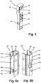
- the inner connector part 31 shown is a cuboid injection-molded part made of plastic and has an upper and a lower through hole 34 for the screws 33, a central through hole 35 arranged between them and at the level of the upper through hole 34 on both sides with a laterally protruding plug-in or hanging projection 36 an inclined side edge 37 on.
- a pin 38 on the central through hole 35, together with an associated contour 24 of the longitudinal channel 22, ensures that the inner connector part 31 is mounted on the cross member hollow profile 20 in a manner that is secure against rotation.
- the outer connector part 32 shown is an injection-molded part made of plastic and is U-shaped with a central leg 40 and two side legs 41 .
- the center leg 41 has an upper and a lower pin 42 on the outside and a central through hole 43 between them.
- the two side legs 41 each have on the inside an upwardly open, upper and a downwardly open, lower plug-in or hanging receptacle 44 with an inclined side edge 45 .
- the center leg 40 is narrower than the distance between the two side legs 41 and passes via a respective inclined surface 46 in the two side arms 41 through, whereby between the inclined surfaces 46 and the side legs 41 each extends an outside locking step 47th
- the outer connector part 32 is mirror-symmetrical with respect to the transverse center plane passing through the central through hole 43.
- the inner connector parts 31 can be hung with their hanging projections 36 in the upper hanging receptacles 44 of the outer connector parts 32, the co-operating sloping side edges 37, 46 causing the two connector parts 31, 32 to be tightened in the longitudinal direction of the hollow cross-member 20.
- the tension bolt 51 is inserted through the central through holes 35, 43 and into the guide bore 58 of the guide housing 55 until the tension bolt 51 with its bolt head, namely with the sleeve edge of the sleeve nut 54, rests on the outside of the middle leg 40 of the outer connector part 32.
- the bolt head protrudes beyond the center leg 40 on both sides.
- the threaded pin 56 is screwed in so far that it slightly engages with its conical pin end in the transverse bore 53 and thereby secures the tension bolt 51 in the guide housing 55.
- the tensioning unit 50 is now fixed on the hollow cross member 20, and the pre-assembly of the lowest and uppermost cross member 3 1 , 3 2 is completed.
- the pillar hollow profiles 10, the traverse hollow profiles 20 and two perforated strips 60 are cut to length.
- the perforated grid strips 60 have holes 61 at equidistant intervals, for example in the usual furniture grid of 32 mm.
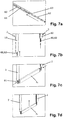
- An LED strip 62 is pushed into a C-groove 63 of the breadboard 60 and is held in it by clamping ( Figure 7a ) .
- the perforated grid strips 60 and the LED strips 62 are each about the height of the top traverse 3 2 shorter than the pillar hollow profiles 10.
- the perforated grid strips 60 are made of translucent plastic and are therefore transparent to the light emitted by the LED strip 60.
- the cables of the LED strips 62 are not shown.
- the perforated grid strips 60 backed by the LED strips 62 are pushed into the pillar hollow profiles 10, which are open at the end, between the two longitudinal ribs 13 ( Figure 7b ) to form the pillars 2.
- the perforated strips are in place 60 by about the height of a traverse down from the pillar hollow profile 10.
- the preassembled bottom cross member 3 1 is positioned between the downwardly protruding perforated grid strips 60, and then the two columns 2 are pushed together until the pins 42 of the outer connector parts 32 are inserted into the holes 61 of the perforated grid strips 60 ( Figure 7c ).
- the tie bolt 51 is centered with its transverse bore 53 on the conical pin end of the threaded pin 56.
- the bolt head and the threaded pin 56 are drawn towards each other and thus the hollow column profile 10, which is engaged from behind by the tension bolt 51, and the hollow cross member 10 are clamped together.
- the transverse bore 53 can also have an insertion cone that interacts with the threaded pin 56.
- the preassembled top crossmember 3 2 can be inserted between the two pillars 2 from above ( Fig. 7f ) until its upper edge is flush with the pillars 2.
- the top traverse 3 2 thus does not engage in the perforated grid strip 60 and is not tied to the height grid dimension.
- the top traverse 3 2 is fastened like the bottom traverse 3 1 using the screwdriver 70 ( Fig. 7g ).
- a central cross member 3 3 To fasten a central cross member 3 3 , its two outer connector parts 3 2 are first clipped into the longitudinal groove 11 of the pillar hollow profiles 10 and at the same time the pins 42 of the outer connector parts 32 are inserted into the holes 61 of the perforated grid strips 60 ( Fig. 7h ).
- the two side legs 41 of the outer connector part 32 spring slightly inward until their locking steps 47 are locked behind the locking steps 15 of the pillar hollow profile 10.
- the outer connector parts 32 can be removed again and repositioned.
- the middle traverse 3 3 is positioned between the pillars 2 ( Figure 7i ) and hung with their inner connector parts 31 from above into the two latched outer connector parts 32 ( Fig. 7j ).
- the perforated grid strips 60 form the load transfer organs of the central cross members 3 3 . Since it is not the cut lower edge, but rather the holes 61 of the perforated grid strip 60 that form the height reference, a high tolerance is possible when cutting the perforated grid strip.
- the interior of the outer connector parts 32 is filled by the suspended inner connector parts 31, so that the side legs 41 of the outer connector parts 32 cannot be deflected inward and thus the outer connector parts 32 cannot be detached from the columns 2.
- Interface holes for transverse fastening elements (for example cross screws) of add-on elements (for example furniture fittings) lead through the pillar hollow profile 10 and the cross member connectors 31, 32.
- Fig. 5 are the interface holes 39 of the inner connector part 31 and in Figs. 6a, 6b the interface holes 48 of the outer connector portion 32 are shown.
- the light emitted by the LED strips 62 through the perforated grid strips 60 emerges from the longitudinal grooves 11 of the pillar hollow profiles 10 and provides "ambient lighting" for the frame structure 1.
- the heat is dissipated from the LED strips 62 to the rear of the pillar hollow profiles 10.
Landscapes
- Engineering & Computer Science (AREA)
- General Engineering & Computer Science (AREA)
- Mechanical Engineering (AREA)
- Health & Medical Sciences (AREA)
- Public Health (AREA)
- Mutual Connection Of Rods And Tubes (AREA)
Claims (13)
- Structure d'encadrement (1) notamment dévolue à un système de rayonnage, comprenant :- deux colonnes (2) notamment verticales, revêtant respectivement la forme d'un profilé creux (10) notamment rectangulaire, muni d'une rainure longitudinale (11) dont les deux ailes (12) opposées l'une à l'autre sont intérieurement pourvues, à chaque fois, de deux nervures longitudinales (13) entre lesquelles une barrette (60) à trame perforée est insérée dans ledit profilé creux (10) des colonnes, et- plusieurs traverses (31, 32, 33) notamment horizontales, fixées aux deux colonnes (2) et revêtant, à chaque fois, la forme d'un profilé creux (20) notamment rectangulaire, aux faces extrêmes respectives duquel est fixé un élément (30) de liaison desdites traverses,sachant que les éléments (30) de liaison des traverses sont respectivement constitués de deux parties matérialisées par des parties de liaison (31, 32) intérieure et extérieure, la partie intérieure de liaison (31) étant fixée frontalement au profilé creux (20) desdites traverses et étant emboîtée, notamment accrochée dans la partie extérieure de liaison (32), et ladite partie extérieure de liaison (32) pénétrant, par au moins un tenon (42), dans l'un des trous (61) des barrettes (60) à trame perforée, et
sachant que les deux ailes (12) de la rainure du profilé creux (10) des colonnes, et la partie extérieure de liaison (32), sont respectivement dotées d'un profil de clipsage (15, 46, 47) à coopération mutuelle, affecté à l'insertion clipsée de ladite partie extérieure de liaison (32) dans la rainure longitudinale (11), et/ou au coulissement de ladite partie extérieure de liaison (32) le long de ladite rainure longitudinale (11). - Structure d'encadrement selon la revendication 1, caractérisée par le fait que les barrettes (60) à trame perforée consistent en un matériau translucide, notamment en une matière plastique ; et par le fait qu'un ruban (62) à diodes électroluminescentes est respectivement disposé, notamment collé à la face postérieure desdites barrettes (60) à trame perforée, ou est logé dans une rainure en C (63) de la barrette (60) à trame perforée.
- Structure d'encadrement selon la revendication 1 ou 2, caractérisée par le fait que les barrettes (60) à trame perforée comportent des trous (61) pratiqués à équidistance.
- Structure d'encadrement selon l'une des revendications précédentes, caractérisée par le fait que les barrettes (60) à trame perforée sont plus courtes que les profilés creux (10) des colonnes, d'une valeur représentant, à chaque fois, sensiblement la hauteur de la traverse (32) supérieure extrême.
- Structure d'encadrement selon l'une des revendications précédentes, caractérisée par le fait qu'au moins les traverses (31, 32) inférieure extrême, et supérieure extrême, sont reliées rigidement aux colonnes (2).
- Structure d'encadrement selon l'une des revendications précédentes, caractérisée par le fait qu'une traverse médiane (33) est retenue en suspension sur les colonnes (2).
- Structure d'encadrement selon l'une des revendications précédentes, caractérisée par le fait que la partie intérieure de liaison (31) est fixée frontalement au profilé creux (20) des traverses, au moyen d'une vis (33) vissée dans un canal de vissage (21) dudit profilé creux (20) des traverses.
- Structure d'encadrement selon l'une des revendications précédentes, caractérisée par le fait que les deux parties de liaison (31, 32) sont respectivement pourvues d'un profil de blocage (37, 46) s'étendant à l'oblique par rapport à la direction d'emboîtement afin de bloquer l'une contre l'autre lesdites parties de liaison (31, 32), emboîtées l'une dans l'autre, transversalement par rapport à ladite direction d'emboîtement.
- Structure d'encadrement selon l'une des revendications précédentes, caractérisée par le fait qu'un boulon de blocage (51) est enfiché dans un canal longitudinal (22) du profilé creux (20) des traverses, en franchissant de part en part les deux parties de liaison (31, 32), et est extérieurement en applique, contre la partie extérieure de liaison (32), par une tête qui vient respectivement en prise par-derrière avec un épaulement longitudinal (14) du profilé creux (10) des colonnes, situé en amont des deux nervures longitudinales (13), et peut être insérée plus avant dans ledit canal longitudinal (22) au moyen d'un élément de serrage (56) s'étendant transversalement dans ledit profilé creux (20) des traverses, dans lequel il est notamment vissé, de manière à bloquer la traverse (31, 32) sur la colonne (2) considérée.
- Structure d'encadrement selon la revendication 9, caractérisée par le fait que l'élément de serrage (56) pénètre dans un alésage transversal (53) du boulon de blocage (51) ; et par le fait que ledit élément de serrage (56) et/ou ledit alésage transversal (53) est (sont) conçu(s) avec obliquité mutuelle de telle sorte que, lors de la pénétration, ledit boulon de blocage (51) soit centré sur ledit élément de serrage (56), et soit ainsi bloqué.
- Structure d'encadrement selon l'une des revendications précédentes, caractérisée par le fait que les éléments (30) de liaison des traverses comportent des trous d'interfaces (39, 48) destinés à des éléments de fixation d'éléments rapportés, s'étendant transversalement.
- Structure d'encadrement selon l'une des revendications précédentes, caractérisée par le fait que les profilés creux (10) des colonnes et/ou les profilés creux (20) des traverses sont des profilés venus d'extrusion, notamment en métal.
- Structure d'encadrement selon l'une des revendications précédentes, caractérisée par le fait que les éléments (30) de liaison des traverses sont constitués d'une matière plastique.
Priority Applications (1)
| Application Number | Priority Date | Filing Date | Title |
|---|---|---|---|
| PL18711554T PL3614885T3 (pl) | 2017-04-25 | 2018-03-15 | Konstrukcja ramowa dla systemu regałowego |
Applications Claiming Priority (2)
| Application Number | Priority Date | Filing Date | Title |
|---|---|---|---|
| DE202017102414.8U DE202017102414U1 (de) | 2017-04-25 | 2017-04-25 | Rahmenkonstruktion für ein Regalsystem |
| PCT/EP2018/056553 WO2018197101A1 (fr) | 2017-04-25 | 2018-03-15 | Structure de cadre pour système d'étagères |
Publications (2)
| Publication Number | Publication Date |
|---|---|
| EP3614885A1 EP3614885A1 (fr) | 2020-03-04 |
| EP3614885B1 true EP3614885B1 (fr) | 2021-04-28 |
Family
ID=59069317
Family Applications (1)
| Application Number | Title | Priority Date | Filing Date |
|---|---|---|---|
| EP18711554.8A Active EP3614885B1 (fr) | 2017-04-25 | 2018-03-15 | Structure de cadre pour système d'étagères |
Country Status (6)
| Country | Link |
|---|---|
| US (1) | US10779650B2 (fr) |
| EP (1) | EP3614885B1 (fr) |
| DE (1) | DE202017102414U1 (fr) |
| ES (1) | ES2875379T3 (fr) |
| PL (1) | PL3614885T3 (fr) |
| WO (1) | WO2018197101A1 (fr) |
Families Citing this family (3)
| Publication number | Priority date | Publication date | Assignee | Title |
|---|---|---|---|---|
| RU198670U1 (ru) * | 2020-01-27 | 2020-07-21 | Общество С Ограниченной Ответственностью "Интал" | Рамочный профиль |
| CN115667735A (zh) * | 2022-01-27 | 2023-01-31 | 纳塔蓬·阿内卡达纳 | 用于与铝制家具的套筒接头连接的带凹槽的内墙框架 |
| CN114614176A (zh) * | 2022-03-25 | 2022-06-10 | 中创新航科技股份有限公司 | 储能机架 |
Citations (1)
| Publication number | Priority date | Publication date | Assignee | Title |
|---|---|---|---|---|
| US5520292A (en) * | 1994-05-16 | 1996-05-28 | Lombardi; Donald G. | Percussion instrument mounting apparatus |
Family Cites Families (14)
| Publication number | Priority date | Publication date | Assignee | Title |
|---|---|---|---|---|
| SE334450B (fr) * | 1963-09-03 | 1971-04-26 | Kooperativa Foerbundet | |
| CA998819A (en) * | 1974-05-10 | 1976-10-26 | Jacques Canin | Knock-down joint between frame members |
| US4055253A (en) * | 1976-07-21 | 1977-10-25 | Oztekin Muammer A | Merchandise display unit |
| US4712286A (en) * | 1983-05-19 | 1987-12-15 | Wolf Morris A | Method for making merchandising display members |
| US4585131A (en) * | 1983-12-19 | 1986-04-29 | Amstore Corporation | Variable decor merchandising system |
| US4653652A (en) * | 1985-01-25 | 1987-03-31 | Frank Avati | Construction system |
| US6047838A (en) * | 1997-03-14 | 2000-04-11 | Kewaunee Scientific Corp. | Modular support post |
| DE29917734U1 (de) * | 1999-10-07 | 2001-02-08 | Halfen GmbH & Co. Kommanditgesellschaft, 40764 Langenfeld | Aus einem Profilelement gebildete Montageschiene |
| DE10045539A1 (de) * | 2000-09-13 | 2002-03-21 | Halfen Gmbh & Co Kg | Verbindungsteil für Montageschienen |
| US7165690B2 (en) * | 2004-10-21 | 2007-01-23 | Bmp Furniture Industrial Co., Ltd. | Post structure |
| US20080000861A1 (en) * | 2006-06-13 | 2008-01-03 | Megawall Llc | Slatwall adapter |
| US7950531B2 (en) * | 2006-06-23 | 2011-05-31 | Adc Gmbh | Mounting arrangement for a standard telecommunications panel |
| SE534247C2 (sv) * | 2009-10-23 | 2011-06-14 | Clamco Invest Ab | Hölje för elektronisk utrustning, innefattande fästanordning |
| US9596948B1 (en) * | 2013-02-06 | 2017-03-21 | Megawall, Inc. | Free-standing slatwall |
-
2017
- 2017-04-25 DE DE202017102414.8U patent/DE202017102414U1/de not_active Expired - Lifetime
-
2018
- 2018-03-15 PL PL18711554T patent/PL3614885T3/pl unknown
- 2018-03-15 ES ES18711554T patent/ES2875379T3/es active Active
- 2018-03-15 EP EP18711554.8A patent/EP3614885B1/fr active Active
- 2018-03-15 WO PCT/EP2018/056553 patent/WO2018197101A1/fr unknown
-
2019
- 2019-08-28 US US16/554,508 patent/US10779650B2/en active Active
Patent Citations (1)
| Publication number | Priority date | Publication date | Assignee | Title |
|---|---|---|---|---|
| US5520292A (en) * | 1994-05-16 | 1996-05-28 | Lombardi; Donald G. | Percussion instrument mounting apparatus |
Also Published As
| Publication number | Publication date |
|---|---|
| US20190380493A1 (en) | 2019-12-19 |
| PL3614885T3 (pl) | 2021-10-04 |
| EP3614885A1 (fr) | 2020-03-04 |
| ES2875379T3 (es) | 2021-11-10 |
| WO2018197101A1 (fr) | 2018-11-01 |
| DE202017102414U1 (de) | 2017-05-31 |
| US10779650B2 (en) | 2020-09-22 |
Similar Documents
| Publication | Publication Date | Title |
|---|---|---|
| DE2618442C2 (de) | Stütze für ein Geländer oder dergleichen | |
| EP3614885B1 (fr) | Structure de cadre pour système d'étagères | |
| EP0616088A1 (fr) | Couverture à résille plane ou spatiale, en particulier couverture à résille adaptée à la marche, formée de profiles et de noeuds | |
| WO2020049374A1 (fr) | Ferrure d'ajustage et système de support pour modules solaires | |
| DE19828189C1 (de) | Pfosten-Riegel-Verbindung | |
| AT509484B1 (de) | Haltevorrichtung zum verbinden von profilen zu einem flächigen wandelement | |
| DE10251489A1 (de) | Zaunpfostensystem | |
| EP1129644A1 (fr) | Rayonnage | |
| EP1081300A2 (fr) | Bâtiment | |
| EP3574163B1 (fr) | Set et structure de cadre pour une estrade, une scène et/ou une tribune | |
| DE202006007455U1 (de) | Zaunelement | |
| EP3293336A1 (fr) | Rail de retenue pour un balcon français ainsi que dispositif et système de retenue associés | |
| DE102017000924A1 (de) | Plattenhalter | |
| DE3642846C2 (fr) | ||
| EP3263788A1 (fr) | Liaison de deux poutres en bois | |
| EP3696361B1 (fr) | Dispositif de support d'éléments de fenêtre ou de porte | |
| DE202024101757U1 (de) | Tragschiene | |
| DE8916173U1 (de) | Möbeleckverbinder | |
| DE19848055C2 (de) | Zuganker | |
| DE20202176U1 (de) | Knotenpunktteil und Bauwerk mit einem solchen Knotenpunktteil | |
| DE202020103287U1 (de) | Nachrüstsatz für ein Fenstergitter | |
| DE102020207149A1 (de) | Nachrüstsatz für ein Fenstergitter | |
| EP2388412B1 (fr) | Elément de cadre | |
| DE19622735A1 (de) | Kupplungsanordnung | |
| DE102009049588A1 (de) | Sichtschutzvorrichtung |
Legal Events
| Date | Code | Title | Description |
|---|---|---|---|
| STAA | Information on the status of an ep patent application or granted ep patent |
Free format text: STATUS: UNKNOWN |
|
| STAA | Information on the status of an ep patent application or granted ep patent |
Free format text: STATUS: THE INTERNATIONAL PUBLICATION HAS BEEN MADE |
|
| PUAI | Public reference made under article 153(3) epc to a published international application that has entered the european phase |
Free format text: ORIGINAL CODE: 0009012 |
|
| STAA | Information on the status of an ep patent application or granted ep patent |
Free format text: STATUS: REQUEST FOR EXAMINATION WAS MADE |
|
| 17P | Request for examination filed |
Effective date: 20191125 |
|
| AK | Designated contracting states |
Kind code of ref document: A1 Designated state(s): AL AT BE BG CH CY CZ DE DK EE ES FI FR GB GR HR HU IE IS IT LI LT LU LV MC MK MT NL NO PL PT RO RS SE SI SK SM TR |
|
| AX | Request for extension of the european patent |
Extension state: BA ME |
|
| RIN1 | Information on inventor provided before grant (corrected) |
Inventor name: EBEL, CONSTANTIN Inventor name: KUGEL, JASMIN |
|
| DAV | Request for validation of the european patent (deleted) | ||
| DAX | Request for extension of the european patent (deleted) | ||
| STAA | Information on the status of an ep patent application or granted ep patent |
Free format text: STATUS: EXAMINATION IS IN PROGRESS |
|
| STAA | Information on the status of an ep patent application or granted ep patent |
Free format text: STATUS: EXAMINATION IS IN PROGRESS |
|
| 17Q | First examination report despatched |
Effective date: 20200921 |
|
| GRAP | Despatch of communication of intention to grant a patent |
Free format text: ORIGINAL CODE: EPIDOSNIGR1 |
|
| STAA | Information on the status of an ep patent application or granted ep patent |
Free format text: STATUS: GRANT OF PATENT IS INTENDED |
|
| GRAS | Grant fee paid |
Free format text: ORIGINAL CODE: EPIDOSNIGR3 |
|
| GRAA | (expected) grant |
Free format text: ORIGINAL CODE: 0009210 |
|
| STAA | Information on the status of an ep patent application or granted ep patent |
Free format text: STATUS: THE PATENT HAS BEEN GRANTED |
|
| INTG | Intention to grant announced |
Effective date: 20210301 |
|
| AK | Designated contracting states |
Kind code of ref document: B1 Designated state(s): AL AT BE BG CH CY CZ DE DK EE ES FI FR GB GR HR HU IE IS IT LI LT LU LV MC MK MT NL NO PL PT RO RS SE SI SK SM TR |
|
| REG | Reference to a national code |
Ref country code: GB Ref legal event code: FG4D Free format text: NOT ENGLISH |
|
| REG | Reference to a national code |
Ref country code: CH Ref legal event code: EP |
|
| REG | Reference to a national code |
Ref country code: AT Ref legal event code: REF Ref document number: 1386124 Country of ref document: AT Kind code of ref document: T Effective date: 20210515 |
|
| REG | Reference to a national code |
Ref country code: DE Ref legal event code: R096 Ref document number: 502018005008 Country of ref document: DE |
|
| REG | Reference to a national code |
Ref country code: IE Ref legal event code: FG4D Free format text: LANGUAGE OF EP DOCUMENT: GERMAN |
|
| REG | Reference to a national code |
Ref country code: LT Ref legal event code: MG9D |
|
| PG25 | Lapsed in a contracting state [announced via postgrant information from national office to epo] |
Ref country code: LT Free format text: LAPSE BECAUSE OF FAILURE TO SUBMIT A TRANSLATION OF THE DESCRIPTION OR TO PAY THE FEE WITHIN THE PRESCRIBED TIME-LIMIT Effective date: 20210428 Ref country code: HR Free format text: LAPSE BECAUSE OF FAILURE TO SUBMIT A TRANSLATION OF THE DESCRIPTION OR TO PAY THE FEE WITHIN THE PRESCRIBED TIME-LIMIT Effective date: 20210428 Ref country code: FI Free format text: LAPSE BECAUSE OF FAILURE TO SUBMIT A TRANSLATION OF THE DESCRIPTION OR TO PAY THE FEE WITHIN THE PRESCRIBED TIME-LIMIT Effective date: 20210428 Ref country code: NL Free format text: LAPSE BECAUSE OF FAILURE TO SUBMIT A TRANSLATION OF THE DESCRIPTION OR TO PAY THE FEE WITHIN THE PRESCRIBED TIME-LIMIT Effective date: 20210428 Ref country code: BG Free format text: LAPSE BECAUSE OF FAILURE TO SUBMIT A TRANSLATION OF THE DESCRIPTION OR TO PAY THE FEE WITHIN THE PRESCRIBED TIME-LIMIT Effective date: 20210728 |
|
| REG | Reference to a national code |
Ref country code: ES Ref legal event code: FG2A Ref document number: 2875379 Country of ref document: ES Kind code of ref document: T3 Effective date: 20211110 |
|
| PG25 | Lapsed in a contracting state [announced via postgrant information from national office to epo] |
Ref country code: SE Free format text: LAPSE BECAUSE OF FAILURE TO SUBMIT A TRANSLATION OF THE DESCRIPTION OR TO PAY THE FEE WITHIN THE PRESCRIBED TIME-LIMIT Effective date: 20210428 Ref country code: RS Free format text: LAPSE BECAUSE OF FAILURE TO SUBMIT A TRANSLATION OF THE DESCRIPTION OR TO PAY THE FEE WITHIN THE PRESCRIBED TIME-LIMIT Effective date: 20210428 Ref country code: PT Free format text: LAPSE BECAUSE OF FAILURE TO SUBMIT A TRANSLATION OF THE DESCRIPTION OR TO PAY THE FEE WITHIN THE PRESCRIBED TIME-LIMIT Effective date: 20210830 Ref country code: LV Free format text: LAPSE BECAUSE OF FAILURE TO SUBMIT A TRANSLATION OF THE DESCRIPTION OR TO PAY THE FEE WITHIN THE PRESCRIBED TIME-LIMIT Effective date: 20210428 Ref country code: NO Free format text: LAPSE BECAUSE OF FAILURE TO SUBMIT A TRANSLATION OF THE DESCRIPTION OR TO PAY THE FEE WITHIN THE PRESCRIBED TIME-LIMIT Effective date: 20210728 Ref country code: GR Free format text: LAPSE BECAUSE OF FAILURE TO SUBMIT A TRANSLATION OF THE DESCRIPTION OR TO PAY THE FEE WITHIN THE PRESCRIBED TIME-LIMIT Effective date: 20210729 Ref country code: IS Free format text: LAPSE BECAUSE OF FAILURE TO SUBMIT A TRANSLATION OF THE DESCRIPTION OR TO PAY THE FEE WITHIN THE PRESCRIBED TIME-LIMIT Effective date: 20210828 |
|
| REG | Reference to a national code |
Ref country code: NL Ref legal event code: MP Effective date: 20210428 |
|
| PG25 | Lapsed in a contracting state [announced via postgrant information from national office to epo] |
Ref country code: DK Free format text: LAPSE BECAUSE OF FAILURE TO SUBMIT A TRANSLATION OF THE DESCRIPTION OR TO PAY THE FEE WITHIN THE PRESCRIBED TIME-LIMIT Effective date: 20210428 Ref country code: RO Free format text: LAPSE BECAUSE OF FAILURE TO SUBMIT A TRANSLATION OF THE DESCRIPTION OR TO PAY THE FEE WITHIN THE PRESCRIBED TIME-LIMIT Effective date: 20210428 Ref country code: EE Free format text: LAPSE BECAUSE OF FAILURE TO SUBMIT A TRANSLATION OF THE DESCRIPTION OR TO PAY THE FEE WITHIN THE PRESCRIBED TIME-LIMIT Effective date: 20210428 Ref country code: SM Free format text: LAPSE BECAUSE OF FAILURE TO SUBMIT A TRANSLATION OF THE DESCRIPTION OR TO PAY THE FEE WITHIN THE PRESCRIBED TIME-LIMIT Effective date: 20210428 Ref country code: SK Free format text: LAPSE BECAUSE OF FAILURE TO SUBMIT A TRANSLATION OF THE DESCRIPTION OR TO PAY THE FEE WITHIN THE PRESCRIBED TIME-LIMIT Effective date: 20210428 |
|
| REG | Reference to a national code |
Ref country code: DE Ref legal event code: R097 Ref document number: 502018005008 Country of ref document: DE |
|
| PLBE | No opposition filed within time limit |
Free format text: ORIGINAL CODE: 0009261 |
|
| STAA | Information on the status of an ep patent application or granted ep patent |
Free format text: STATUS: NO OPPOSITION FILED WITHIN TIME LIMIT |
|
| 26N | No opposition filed |
Effective date: 20220131 |
|
| PG25 | Lapsed in a contracting state [announced via postgrant information from national office to epo] |
Ref country code: IS Free format text: LAPSE BECAUSE OF FAILURE TO SUBMIT A TRANSLATION OF THE DESCRIPTION OR TO PAY THE FEE WITHIN THE PRESCRIBED TIME-LIMIT Effective date: 20210828 Ref country code: AL Free format text: LAPSE BECAUSE OF FAILURE TO SUBMIT A TRANSLATION OF THE DESCRIPTION OR TO PAY THE FEE WITHIN THE PRESCRIBED TIME-LIMIT Effective date: 20210428 |
|
| PG25 | Lapsed in a contracting state [announced via postgrant information from national office to epo] |
Ref country code: MC Free format text: LAPSE BECAUSE OF FAILURE TO SUBMIT A TRANSLATION OF THE DESCRIPTION OR TO PAY THE FEE WITHIN THE PRESCRIBED TIME-LIMIT Effective date: 20210428 |
|
| REG | Reference to a national code |
Ref country code: BE Ref legal event code: MM Effective date: 20220331 |
|
| PG25 | Lapsed in a contracting state [announced via postgrant information from national office to epo] |
Ref country code: LU Free format text: LAPSE BECAUSE OF NON-PAYMENT OF DUE FEES Effective date: 20220315 Ref country code: IE Free format text: LAPSE BECAUSE OF NON-PAYMENT OF DUE FEES Effective date: 20220315 |
|
| PG25 | Lapsed in a contracting state [announced via postgrant information from national office to epo] |
Ref country code: BE Free format text: LAPSE BECAUSE OF NON-PAYMENT OF DUE FEES Effective date: 20220331 |
|
| PGFP | Annual fee paid to national office [announced via postgrant information from national office to epo] |
Ref country code: FR Payment date: 20230320 Year of fee payment: 6 Ref country code: CZ Payment date: 20230303 Year of fee payment: 6 |
|
| PGFP | Annual fee paid to national office [announced via postgrant information from national office to epo] |
Ref country code: PL Payment date: 20230217 Year of fee payment: 6 |
|
| PGFP | Annual fee paid to national office [announced via postgrant information from national office to epo] |
Ref country code: IT Payment date: 20230331 Year of fee payment: 6 Ref country code: ES Payment date: 20230414 Year of fee payment: 6 Ref country code: CH Payment date: 20230402 Year of fee payment: 6 |
|
| P01 | Opt-out of the competence of the unified patent court (upc) registered |
Effective date: 20230630 |
|
| PGFP | Annual fee paid to national office [announced via postgrant information from national office to epo] |
Ref country code: AT Payment date: 20240318 Year of fee payment: 7 |
|
| PG25 | Lapsed in a contracting state [announced via postgrant information from national office to epo] |
Ref country code: MK Free format text: LAPSE BECAUSE OF FAILURE TO SUBMIT A TRANSLATION OF THE DESCRIPTION OR TO PAY THE FEE WITHIN THE PRESCRIBED TIME-LIMIT Effective date: 20210428 Ref country code: CY Free format text: LAPSE BECAUSE OF FAILURE TO SUBMIT A TRANSLATION OF THE DESCRIPTION OR TO PAY THE FEE WITHIN THE PRESCRIBED TIME-LIMIT Effective date: 20210428 |
|
| PGFP | Annual fee paid to national office [announced via postgrant information from national office to epo] |
Ref country code: DE Payment date: 20240325 Year of fee payment: 7 Ref country code: GB Payment date: 20240322 Year of fee payment: 7 |
|
| PG25 | Lapsed in a contracting state [announced via postgrant information from national office to epo] |
Ref country code: HU Free format text: LAPSE BECAUSE OF FAILURE TO SUBMIT A TRANSLATION OF THE DESCRIPTION OR TO PAY THE FEE WITHIN THE PRESCRIBED TIME-LIMIT; INVALID AB INITIO Effective date: 20180315 |
|
| PGFP | Annual fee paid to national office [announced via postgrant information from national office to epo] |
Ref country code: TR Payment date: 20240304 Year of fee payment: 7 |
|
| PG25 | Lapsed in a contracting state [announced via postgrant information from national office to epo] |
Ref country code: MT Free format text: LAPSE BECAUSE OF FAILURE TO SUBMIT A TRANSLATION OF THE DESCRIPTION OR TO PAY THE FEE WITHIN THE PRESCRIBED TIME-LIMIT Effective date: 20210428 |