EP3613933A1 - Dispositif de surveillance de portes, fenêtres ou analogues - Google Patents
Dispositif de surveillance de portes, fenêtres ou analogues Download PDFInfo
- Publication number
- EP3613933A1 EP3613933A1 EP19190998.5A EP19190998A EP3613933A1 EP 3613933 A1 EP3613933 A1 EP 3613933A1 EP 19190998 A EP19190998 A EP 19190998A EP 3613933 A1 EP3613933 A1 EP 3613933A1
- Authority
- EP
- European Patent Office
- Prior art keywords
- sensors
- sensor
- another
- door
- automatic
- Prior art date
- Legal status (The legal status is an assumption and is not a legal conclusion. Google has not performed a legal analysis and makes no representation as to the accuracy of the status listed.)
- Granted
Links
- 238000012544 monitoring process Methods 0.000 title claims abstract description 14
- 238000013459 approach Methods 0.000 claims abstract description 5
- 238000001514 detection method Methods 0.000 claims description 18
- 238000000034 method Methods 0.000 claims description 17
- 238000011156 evaluation Methods 0.000 claims description 13
- 238000004891 communication Methods 0.000 claims description 9
- 239000000463 material Substances 0.000 claims description 7
- 230000003287 optical effect Effects 0.000 claims description 6
- 239000002184 metal Substances 0.000 claims description 3
- 238000011423 initialization method Methods 0.000 claims description 2
- 239000011159 matrix material Substances 0.000 claims description 2
- 230000008054 signal transmission Effects 0.000 claims description 2
- 238000005286 illumination Methods 0.000 claims 1
- 230000033001 locomotion Effects 0.000 description 4
- 238000013461 design Methods 0.000 description 2
- 238000005516 engineering process Methods 0.000 description 2
- 230000004913 activation Effects 0.000 description 1
- 238000003491 array Methods 0.000 description 1
Images


Classifications
-
- G—PHYSICS
- G01—MEASURING; TESTING
- G01S—RADIO DIRECTION-FINDING; RADIO NAVIGATION; DETERMINING DISTANCE OR VELOCITY BY USE OF RADIO WAVES; LOCATING OR PRESENCE-DETECTING BY USE OF THE REFLECTION OR RERADIATION OF RADIO WAVES; ANALOGOUS ARRANGEMENTS USING OTHER WAVES
- G01S13/00—Systems using the reflection or reradiation of radio waves, e.g. radar systems; Analogous systems using reflection or reradiation of waves whose nature or wavelength is irrelevant or unspecified
- G01S13/02—Systems using reflection of radio waves, e.g. primary radar systems; Analogous systems
- G01S13/06—Systems determining position data of a target
- G01S13/08—Systems for measuring distance only
-
- E—FIXED CONSTRUCTIONS
- E05—LOCKS; KEYS; WINDOW OR DOOR FITTINGS; SAFES
- E05F—DEVICES FOR MOVING WINGS INTO OPEN OR CLOSED POSITION; CHECKS FOR WINGS; WING FITTINGS NOT OTHERWISE PROVIDED FOR, CONCERNED WITH THE FUNCTIONING OF THE WING
- E05F15/00—Power-operated mechanisms for wings
- E05F15/40—Safety devices, e.g. detection of obstructions or end positions
- E05F15/42—Detection using safety edges
- E05F15/43—Detection using safety edges responsive to disruption of energy beams, e.g. light or sound
-
- E—FIXED CONSTRUCTIONS
- E05—LOCKS; KEYS; WINDOW OR DOOR FITTINGS; SAFES
- E05F—DEVICES FOR MOVING WINGS INTO OPEN OR CLOSED POSITION; CHECKS FOR WINGS; WING FITTINGS NOT OTHERWISE PROVIDED FOR, CONCERNED WITH THE FUNCTIONING OF THE WING
- E05F15/00—Power-operated mechanisms for wings
- E05F15/70—Power-operated mechanisms for wings with automatic actuation
- E05F15/73—Power-operated mechanisms for wings with automatic actuation responsive to movement or presence of persons or objects
-
- G—PHYSICS
- G01—MEASURING; TESTING
- G01S—RADIO DIRECTION-FINDING; RADIO NAVIGATION; DETERMINING DISTANCE OR VELOCITY BY USE OF RADIO WAVES; LOCATING OR PRESENCE-DETECTING BY USE OF THE REFLECTION OR RERADIATION OF RADIO WAVES; ANALOGOUS ARRANGEMENTS USING OTHER WAVES
- G01S13/00—Systems using the reflection or reradiation of radio waves, e.g. radar systems; Analogous systems using reflection or reradiation of waves whose nature or wavelength is irrelevant or unspecified
- G01S13/88—Radar or analogous systems specially adapted for specific applications
- G01S13/93—Radar or analogous systems specially adapted for specific applications for anti-collision purposes
-
- E—FIXED CONSTRUCTIONS
- E05—LOCKS; KEYS; WINDOW OR DOOR FITTINGS; SAFES
- E05F—DEVICES FOR MOVING WINGS INTO OPEN OR CLOSED POSITION; CHECKS FOR WINGS; WING FITTINGS NOT OTHERWISE PROVIDED FOR, CONCERNED WITH THE FUNCTIONING OF THE WING
- E05F15/00—Power-operated mechanisms for wings
- E05F15/70—Power-operated mechanisms for wings with automatic actuation
- E05F15/73—Power-operated mechanisms for wings with automatic actuation responsive to movement or presence of persons or objects
- E05F15/74—Power-operated mechanisms for wings with automatic actuation responsive to movement or presence of persons or objects using photoelectric cells
-
- E—FIXED CONSTRUCTIONS
- E05—LOCKS; KEYS; WINDOW OR DOOR FITTINGS; SAFES
- E05F—DEVICES FOR MOVING WINGS INTO OPEN OR CLOSED POSITION; CHECKS FOR WINGS; WING FITTINGS NOT OTHERWISE PROVIDED FOR, CONCERNED WITH THE FUNCTIONING OF THE WING
- E05F15/00—Power-operated mechanisms for wings
- E05F15/40—Safety devices, e.g. detection of obstructions or end positions
- E05F15/42—Detection using safety edges
- E05F15/43—Detection using safety edges responsive to disruption of energy beams, e.g. light or sound
- E05F2015/434—Detection using safety edges responsive to disruption of energy beams, e.g. light or sound with cameras or optical sensors
- E05F2015/435—Detection using safety edges responsive to disruption of energy beams, e.g. light or sound with cameras or optical sensors by interruption of the beam
-
- E—FIXED CONSTRUCTIONS
- E05—LOCKS; KEYS; WINDOW OR DOOR FITTINGS; SAFES
- E05F—DEVICES FOR MOVING WINGS INTO OPEN OR CLOSED POSITION; CHECKS FOR WINGS; WING FITTINGS NOT OTHERWISE PROVIDED FOR, CONCERNED WITH THE FUNCTIONING OF THE WING
- E05F15/00—Power-operated mechanisms for wings
- E05F15/40—Safety devices, e.g. detection of obstructions or end positions
- E05F15/42—Detection using safety edges
- E05F2015/487—Fault detection of safety edges
-
- E—FIXED CONSTRUCTIONS
- E05—LOCKS; KEYS; WINDOW OR DOOR FITTINGS; SAFES
- E05F—DEVICES FOR MOVING WINGS INTO OPEN OR CLOSED POSITION; CHECKS FOR WINGS; WING FITTINGS NOT OTHERWISE PROVIDED FOR, CONCERNED WITH THE FUNCTIONING OF THE WING
- E05F15/00—Power-operated mechanisms for wings
- E05F15/70—Power-operated mechanisms for wings with automatic actuation
- E05F15/73—Power-operated mechanisms for wings with automatic actuation responsive to movement or presence of persons or objects
- E05F2015/765—Power-operated mechanisms for wings with automatic actuation responsive to movement or presence of persons or objects using optical sensors
-
- E—FIXED CONSTRUCTIONS
- E05—LOCKS; KEYS; WINDOW OR DOOR FITTINGS; SAFES
- E05Y—INDEXING SCHEME ASSOCIATED WITH SUBCLASSES E05D AND E05F, RELATING TO CONSTRUCTION ELEMENTS, ELECTRIC CONTROL, POWER SUPPLY, POWER SIGNAL OR TRANSMISSION, USER INTERFACES, MOUNTING OR COUPLING, DETAILS, ACCESSORIES, AUXILIARY OPERATIONS NOT OTHERWISE PROVIDED FOR, APPLICATION THEREOF
- E05Y2400/00—Electronic control; Electrical power; Power supply; Power or signal transmission; User interfaces
- E05Y2400/10—Electronic control
- E05Y2400/44—Sensors not directly associated with the wing movement
-
- E—FIXED CONSTRUCTIONS
- E05—LOCKS; KEYS; WINDOW OR DOOR FITTINGS; SAFES
- E05Y—INDEXING SCHEME ASSOCIATED WITH SUBCLASSES E05D AND E05F, RELATING TO CONSTRUCTION ELEMENTS, ELECTRIC CONTROL, POWER SUPPLY, POWER SIGNAL OR TRANSMISSION, USER INTERFACES, MOUNTING OR COUPLING, DETAILS, ACCESSORIES, AUXILIARY OPERATIONS NOT OTHERWISE PROVIDED FOR, APPLICATION THEREOF
- E05Y2400/00—Electronic control; Electrical power; Power supply; Power or signal transmission; User interfaces
- E05Y2400/10—Electronic control
- E05Y2400/45—Control modes
- E05Y2400/456—Control modes for programming, e.g. learning or AI [artificial intelligence]
-
- E—FIXED CONSTRUCTIONS
- E05—LOCKS; KEYS; WINDOW OR DOOR FITTINGS; SAFES
- E05Y—INDEXING SCHEME ASSOCIATED WITH SUBCLASSES E05D AND E05F, RELATING TO CONSTRUCTION ELEMENTS, ELECTRIC CONTROL, POWER SUPPLY, POWER SIGNAL OR TRANSMISSION, USER INTERFACES, MOUNTING OR COUPLING, DETAILS, ACCESSORIES, AUXILIARY OPERATIONS NOT OTHERWISE PROVIDED FOR, APPLICATION THEREOF
- E05Y2400/00—Electronic control; Electrical power; Power supply; Power or signal transmission; User interfaces
- E05Y2400/10—Electronic control
- E05Y2400/50—Fault detection
- E05Y2400/502—Fault detection of components
-
- E—FIXED CONSTRUCTIONS
- E05—LOCKS; KEYS; WINDOW OR DOOR FITTINGS; SAFES
- E05Y—INDEXING SCHEME ASSOCIATED WITH SUBCLASSES E05D AND E05F, RELATING TO CONSTRUCTION ELEMENTS, ELECTRIC CONTROL, POWER SUPPLY, POWER SIGNAL OR TRANSMISSION, USER INTERFACES, MOUNTING OR COUPLING, DETAILS, ACCESSORIES, AUXILIARY OPERATIONS NOT OTHERWISE PROVIDED FOR, APPLICATION THEREOF
- E05Y2800/00—Details, accessories and auxiliary operations not otherwise provided for
- E05Y2800/20—Combinations of elements
- E05Y2800/205—Combinations of elements forming a unit
-
- E—FIXED CONSTRUCTIONS
- E05—LOCKS; KEYS; WINDOW OR DOOR FITTINGS; SAFES
- E05Y—INDEXING SCHEME ASSOCIATED WITH SUBCLASSES E05D AND E05F, RELATING TO CONSTRUCTION ELEMENTS, ELECTRIC CONTROL, POWER SUPPLY, POWER SIGNAL OR TRANSMISSION, USER INTERFACES, MOUNTING OR COUPLING, DETAILS, ACCESSORIES, AUXILIARY OPERATIONS NOT OTHERWISE PROVIDED FOR, APPLICATION THEREOF
- E05Y2800/00—Details, accessories and auxiliary operations not otherwise provided for
- E05Y2800/20—Combinations of elements
- E05Y2800/22—Combinations of elements of not identical elements of the same category, e.g. combinations of not identical springs
-
- E—FIXED CONSTRUCTIONS
- E05—LOCKS; KEYS; WINDOW OR DOOR FITTINGS; SAFES
- E05Y—INDEXING SCHEME ASSOCIATED WITH SUBCLASSES E05D AND E05F, RELATING TO CONSTRUCTION ELEMENTS, ELECTRIC CONTROL, POWER SUPPLY, POWER SIGNAL OR TRANSMISSION, USER INTERFACES, MOUNTING OR COUPLING, DETAILS, ACCESSORIES, AUXILIARY OPERATIONS NOT OTHERWISE PROVIDED FOR, APPLICATION THEREOF
- E05Y2900/00—Application of doors, windows, wings or fittings thereof
- E05Y2900/10—Application of doors, windows, wings or fittings thereof for buildings or parts thereof
- E05Y2900/13—Type of wing
- E05Y2900/132—Doors
Definitions
- the present invention relates to a device for monitoring doors, windows or the like for the approach of a person and / or for obstacles in the opening area with a plurality of sensors, associated power supply lines and at least one signal line for transmitting a sensor signal.
- Sensors are used to automatically control drives for doors, windows or the like, as well as to secure the movement of automatic door or window sashes.
- Non-contact sensors are used for this purpose, their physical functional principles and their design are selected to match the corresponding door or window type and the respective required function.
- radar motion detectors are used to control the door movement and active infrared light sensors to safeguard the movement.
- the various sensors are often supplied by different manufacturers and therefore have very different housing designs, connection technologies and commissioning processes.
- the fitter must therefore be familiar with every technology and with the different sensor models from different manufacturers and also have a corresponding variety of spare parts. As a result, the sensors do not have a uniform appearance. Individual documentation is also required for each sensor type.
- the object of the invention is to eliminate these disadvantages.
- the sensors of the device are arranged in succession in a sensor band or sensor strip and are designed as so-called Time of Flight (ToF) sensors.
- ToF Time of Flight
- Different sensor tasks can be implemented with such ToF sensors. They send out an electromagnetic signal, for example a light signal, and receive the signal reflected on an object. The distance between sensor and object is determined from the signal transit time.
- This can be used on the one hand for the detection of obstacles in the opening area of a door or window sash and on the other hand for controlling an automatic door or window sash.
- the sensor tape or sensor strip has a uniform, visually appealing appearance.
- This sensor strip or sensor strip can also be used for any type of door or window, that is to say both for revolving doors, sliding doors, revolving doors, revolving windows, tilting windows and so on. This gives the different types of windows or doors a uniform appearance.
- the sensor strip according to the invention preferably consists of a rigid material, in particular plastic or metal. It is therefore resistant and suitable for permanent use.
- the sensor tape according to the invention preferably consists of flexible material, in particular plastic. As a result, it can advantageously be attached to curved doors or windows, for example revolving doors or curved-arch sliding doors.
- the individual sensor modules are preferably seated on a flexible printed circuit board, which is encased in a flexible material.
- Both the sensor tape and the sensor strip can preferably be produced by the meter. In particular, they can then be cut to length so that they can be adapted to the respective application.
- At least two of the sensors preferably have a different function from one another. At least one sensor is preferably designed to monitor for obstacles, while at least one sensor is preferably designed to monitor for the approach of a person.
- At least one sensor is designed as an array, with a matrix of n x m individual sensors, where n and m each stand for an integer> 1.
- a three-dimensional image of the reflecting surface, ie the background or a detected object, can be recorded by means of sensor arrays.
- the sensors are at least partially the same distance apart.
- a plurality of sensors it is also preferable for a plurality of sensors to be arranged at a smaller distance from one another in at least one area than in at least one other area. This can increase surveillance in certain areas compared to other areas.
- the distance of the sensors from one another can be based in particular on predefined guidelines, for example when monitoring for the pinching of fingers, arms or other parts of the body. Particularly dangerous areas can be protected with a higher sensor density.
- a plurality of sensors are arranged offset to one another transversely to the longitudinal direction of the sensor strip or the sensor strip, in particular in two or more rows parallel to one another.
- the sensor density can advantageously be increased further.
- This can optimal monitoring of obstacles can be achieved.
- One row of sensors can also take over the activation function, while another row of sensors takes over the monitoring function.
- the rows of sensors can also be arranged along two sides of the sensor strip, which enclose an angle of ⁇ 180 °, in particular an angle of 90 °.
- the sensors advantageously have a different orientation from one another or the monitoring field of the sensors of the different sensor rows is different from one another.
- sensors are connected to a common bus line for signal transmission and / or communication with a central control and evaluation unit.
- the common bus line can also be used to supply energy to the sensors, the so-called Powerbus.
- the sensors can communicate individually with the control center.
- the sensors each have an incoming and an outgoing line connection to the bus line, the respective connections preferably being separated from one another before the first start-up or initialization. This is a sequential addressing of the sensors easily possible. The individual addressing is particularly advantageous because it allows a long sensor strip or a long sensor tape to be used without the need for a complex line system.
- At least one sensor in particular all sensors, has an additional function, in particular a display, preferably a luminous display, a lighting means, in particular laser light, or the like.
- a display preferably a luminous display, a lighting means, in particular laser light, or the like.
- the area of application of the sensor strip or the sensor tape can be expanded.
- the detection field height of the individual sensors is preferably individually adjustable, in particular also smaller than the height of a respective sensor relative to a reference surface, in particular a floor, and in particular also dynamically. This allows the detection field height to be adapted to the particular application, for example to a door leaf or a window leaf.
- At least one sensor in particular all sensors, has an optical system, in particular an optical lens.
- the detection field can be focused and / or aligned in the desired manner.
- a device according to the invention of the type described above can be used in particular in an automatic door, in particular a revolving door, sliding door or revolving door, or in an automatic window, in particular a pivoting or tilting window.
- a method for operating an automatic door or an automatic window with a device of the type described above can preferably be characterized in that the height of the detection fields of the sensors is set by an initialization process, in particular by a time-controlled process. Furthermore, such a method is preferably characterized in that the sensors monitor themselves, in particular by emitting a signal when a previously existing background is no longer detected.
- the signal line is monitored for a line break and / or short circuit.
- Each sensor can also be individually parameterized and / or its status can be queried individually.
- the sensors can preferably communicate intelligently with the control center, in particular with clear addressing or without addressing, that is to say message-oriented.
- the addresses of the sensors can preferably be assigned sequentially, in particular starting from the first sensor from the point of view of the control center.
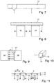
- the in Fig. 1 Sensor strip 1 shown has N time-of-flight sensors (ToF sensors) 2.
- the ToF sensors 2 are arranged one after the other in the longitudinal direction of the sensor strip and each provided with an optical lens 3. This results in a conical detection field 4, and in total a detection area 5.
- the sensors 2 are each connected to two supply lines 6, 7 and a signal and communication line 8 in parallel to one another.
- the supply lines 6, 7 and the signal and communication line 8 are connected to one central control and evaluation unit 9 connected.
- Each sensor 2 is also provided with its own display device 10.
- the height of the detection field H n of the sensors 2 is the same in each case. But it can also, as in Fig. 6 shown to be different.
- the distance W n between the sensors 2 can in each case be the same or different.
- an area of the sensor strip 1 can also be provided with sensors 2 which are at the same distance from one another, and a further area with sensors 2 which have different distances W n from one another or from the first area.
- the sensors 2 can be designed as individual sensors or as a sensor array. Some of the sensors 2 can be designed to monitor for obstacles, another part to control an automatic door or an automatic window.
- the sensors 2 are connected in parallel to the two supply lines 6, 7 and the signal line 8.
- there is exactly one digital signal which is output by any sensor 2 when an obstacle is detected or a person approaches it via the signal line 8.
- each sensor 2 switches the common signal to V- if it detects an object in its detection range. If no sensor 2 is detected, the signal is on the pull-up resistor R to V +.
- Each sensor 2 knows the height H n of its detection field. Various known initialization methods can be used for this. The simplest procedure is a time-controlled procedure and does not require any additional electronics. Each sensor 2 learns as the height H n the distance from the background for a minimum time pending, for example a minute. However, the height of the detection field H n can also be set individually via the communication line 8.
- the sensors 2 can also monitor themselves. As long as a respective sensor 2 sees its background, this sensor knows that it is working. In particular, sensor alignment, optics and electronics are in order. In the event of an error, the respective sensor 2 switches to detection.
- control and evaluation unit 9 can monitor the signal line 8 for line break and / or short circuit.
- Fig. 3 A simple monitoring option is shown in which an analog signal is evaluated by the control and evaluation unit.
- the control and evaluation unit receives the information as to which of the sensors 2 is being detected.
- the control and evaluation unit 9 can individually parameterize each sensor 2, for example the height H n of the monitoring area.
- the control and monitoring unit 9 can query the state of a respective sensor 2 individually.
- the control and evaluation unit 9 can perform additional functions in each sensor 2 (see Fig.
- switch on a laser point that illuminates the detection field on the background during commissioning for example, switch on one or more LEDs that are integrated in the sensor strip or the individual sensors and give an indication to a passerby whether the door is open or locked.
- a display can be switched on that supports the fitter during commissioning.
- each sensor 2 communicates with the control and evaluation unit 9 via communication protocols with unique addressing or those that work without addressing, that is to say message-oriented.
- the address can be assigned to each sensor 2 sequentially, starting from the point of view of the control and evaluation unit 9 first sensor 2 are assigned.
- Each sensor 2 can have an incoming 18 and an outgoing 19 connection to the communication line 8, with the incoming and outgoing connection in each sensor 2 being initially separated. Sequential addressing of sensors 2 is thus possible.
- This configuration is in Fig. 5 shown. It is particularly advantageous since a long sensor strip 1, by the meter, can be used. The actually required length of the sensor strip 1 can then be produced by sawing or cutting off. Remnants can be put together if necessary.
- the sensor strips 1 are preferably mounted in a plastic or metal profile. In the case of a sensor tape, this is preferably mounted in a plastic profile. Here the individual sensor modules sit on a flexible circuit board, which is encased in a flexible material.
- the sensor tape version is bendable and therefore suitable for securing curved elements, for example revolving doors or curved-arch sliding doors.
- the sensor strip 1 according to the invention or the sensor strip 1 according to the invention can be inserted into the hood of a sliding door drive, as shown in FIG Fig. 7 is shown. As a result, the sensor strip or sensor strip is optically subordinate. Likewise, a sensor strip 1 or a sensor strip 1 can be attached to the outside of the hood of a sliding door, as shown in FIG Fig. 8 is shown. In this way, both the closing and the opening of the sliding doors can be secured and the control of the sliding door drive can be effected.
- the sensor strip 1 according to the invention or the sensor strip 1 according to the invention can also be mounted in a moving manner, as shown in Fig. 9 is shown.
- the sensor strip 1 or the sensor strip 1 can be attached to the main closing edge 17 of a sliding leaf 14.
- a sensor tape 1 can preferably be glued on.
- two sensor rows 15, 16 can be attached to a sensor strip 1, in particular on two sides of the sensor strip 1, which form an angle with one another, here 90 °.
- One of the two sensor rows 15 can be used to secure the hinge side or the hinge opposite side, while the other sensor row 16 is used to control the automatic door drive.
- the sensors 2 can as in Fig. 11 also be arranged transversely offset in two rows 15, 16 with respect to the longitudinal direction of the sensor strip 1 or sensor strip 1. The density of the detection area can thereby be increased.
- the bus line 8 can also be designed as a power bus. The sensors then communicate via the two supply lines. A separate communication line is not necessary.
Landscapes
- Engineering & Computer Science (AREA)
- Radar, Positioning & Navigation (AREA)
- Remote Sensing (AREA)
- Physics & Mathematics (AREA)
- Computer Networks & Wireless Communication (AREA)
- General Physics & Mathematics (AREA)
- Electromagnetism (AREA)
- Power-Operated Mechanisms For Wings (AREA)
Applications Claiming Priority (1)
| Application Number | Priority Date | Filing Date | Title |
|---|---|---|---|
| DE102018214215.7A DE102018214215A1 (de) | 2018-08-22 | 2018-08-22 | Vorrichtung zur Überwachung von Türen, Fenstern oder dergleichen |
Publications (2)
| Publication Number | Publication Date |
|---|---|
| EP3613933A1 true EP3613933A1 (fr) | 2020-02-26 |
| EP3613933B1 EP3613933B1 (fr) | 2021-09-29 |
Family
ID=67587624
Family Applications (1)
| Application Number | Title | Priority Date | Filing Date |
|---|---|---|---|
| EP19190998.5A Active EP3613933B1 (fr) | 2018-08-22 | 2019-08-09 | Dispositif de surveillance de portes, fenêtres ou analogues |
Country Status (3)
| Country | Link |
|---|---|
| EP (1) | EP3613933B1 (fr) |
| CN (1) | CN110857980A (fr) |
| DE (1) | DE102018214215A1 (fr) |
Cited By (8)
| Publication number | Priority date | Publication date | Assignee | Title |
|---|---|---|---|---|
| EP3907367A1 (fr) * | 2020-05-08 | 2021-11-10 | GEZE GmbH | Installation de fenêtre automatique |
| EP4043683A1 (fr) | 2021-02-12 | 2022-08-17 | dormakaba Deutschland GmbH | Procédé de fonctionnement d'une installation de porte et installation de porte correspondante |
| EP4043688A1 (fr) | 2021-02-12 | 2022-08-17 | dormakaba Deutschland GmbH | Actionneur de porte et procédé de fonctionnement d'un actionneur de porte |
| EP4043686A1 (fr) | 2021-02-12 | 2022-08-17 | dormakaba Deutschland GmbH | Procédé de fonctionnement d'un actionneur de porte |
| EP4043687A1 (fr) | 2021-02-12 | 2022-08-17 | dormakaba Deutschland GmbH | Procédé de fonctionnement d'un actionneur de porte |
| EP4321722A1 (fr) | 2022-08-12 | 2024-02-14 | dormakaba Deutschland GmbH | Actionneur de porte pour une installation de porte et procédé de fonctionnement d'un tel actionneur de porte |
| EP4321720A1 (fr) | 2022-08-12 | 2024-02-14 | dormakaba Deutschland GmbH | Procédé de fonctionnement d'un actionneur de porte |
| EP4321721A1 (fr) | 2022-08-12 | 2024-02-14 | dormakaba Deutschland GmbH | Procédé permettant de faire fonctionner une installation de porte et installation de porte correspondante |
Families Citing this family (1)
| Publication number | Priority date | Publication date | Assignee | Title |
|---|---|---|---|---|
| DE102020205814A1 (de) | 2020-05-08 | 2021-11-11 | Geze Gmbh | Automatische Fenster- oder Türanlage |
Citations (5)
| Publication number | Priority date | Publication date | Assignee | Title |
|---|---|---|---|---|
| EP0803632A1 (fr) * | 1996-04-26 | 1997-10-29 | Nabco Limited | Capteur de porte avec fonction d'autodiagnostique |
| EP2009215A1 (fr) * | 2007-06-28 | 2008-12-31 | GEZE GmbH | Dispositif de détection pour un dispositiv d'entraînement des portes ou fenêtres |
| EP2226452A1 (fr) * | 2008-12-12 | 2010-09-08 | Pepperl + Fuchs GmbH | Capteur de surveillance de porte |
| CN107859449A (zh) * | 2017-10-24 | 2018-03-30 | 四川星门科技有限公司 | 适用于自动门窗的防撞感应装置 |
| US20180094471A1 (en) * | 2016-10-03 | 2018-04-05 | Magna Mirrors Of America, Inc. | Vehicle window with gesture control |
Family Cites Families (12)
| Publication number | Priority date | Publication date | Assignee | Title |
|---|---|---|---|---|
| EP0567717B1 (fr) * | 1992-04-30 | 2000-08-02 | REER S.p.A. | Barrière optoélectronique |
| DE4415401C1 (de) * | 1994-05-03 | 1995-07-27 | Dorma Gmbh & Co Kg | Vorrichtung zur Überwachung von motorisch angetriebenen Drehflügeltüren |
| DE19712828A1 (de) * | 1997-03-26 | 1998-10-15 | Sick Ag | Lichtgitter und Verfahren zu seiner Herstellung |
| DE10228930B4 (de) * | 2002-06-28 | 2010-11-11 | Geze Gmbh | Sensorvorrichtung für eine automatische Drehtüranlage |
| DE102008044990B4 (de) * | 2008-08-29 | 2014-08-07 | Agtatec Ag | Verfahren und Vorrichtung zur Ansteuerung und/oder Überwachung eines motorisch angetriebenen Flügels während der Öffnungsphase |
| DE102010033818A1 (de) * | 2010-08-09 | 2012-02-09 | Dorma Gmbh + Co. Kg | Sensor |
| EP2453254B1 (fr) * | 2010-11-15 | 2013-01-16 | Cedes AG | Dispositif de surveillance d'une porte doté d'un capteur 3D |
| US20120127317A1 (en) * | 2010-11-19 | 2012-05-24 | Bea, Inc. | Method and device to securely open and close a passageway or access point |
| EP2506034B1 (fr) * | 2011-04-01 | 2013-05-29 | Cedes AG | Dispositif de capteur, dispositif de sécurité, porte et procédé de contrôle du mouvement |
| US10443292B2 (en) * | 2016-04-25 | 2019-10-15 | Magna Closures, Inc. | Non-contact obstacle detection system for motor vehicles |
| GB2552382A (en) * | 2016-07-22 | 2018-01-24 | Airdri Ltd | Sliding door monitoring system and method |
| CN107780750A (zh) * | 2017-10-24 | 2018-03-09 | 四川星门科技有限公司 | 用于智能门的360°扫描防夹结构 |
-
2018
- 2018-08-22 DE DE102018214215.7A patent/DE102018214215A1/de active Pending
-
2019
- 2019-08-09 EP EP19190998.5A patent/EP3613933B1/fr active Active
- 2019-08-22 CN CN201910775980.5A patent/CN110857980A/zh active Pending
Patent Citations (5)
| Publication number | Priority date | Publication date | Assignee | Title |
|---|---|---|---|---|
| EP0803632A1 (fr) * | 1996-04-26 | 1997-10-29 | Nabco Limited | Capteur de porte avec fonction d'autodiagnostique |
| EP2009215A1 (fr) * | 2007-06-28 | 2008-12-31 | GEZE GmbH | Dispositif de détection pour un dispositiv d'entraînement des portes ou fenêtres |
| EP2226452A1 (fr) * | 2008-12-12 | 2010-09-08 | Pepperl + Fuchs GmbH | Capteur de surveillance de porte |
| US20180094471A1 (en) * | 2016-10-03 | 2018-04-05 | Magna Mirrors Of America, Inc. | Vehicle window with gesture control |
| CN107859449A (zh) * | 2017-10-24 | 2018-03-30 | 四川星门科技有限公司 | 适用于自动门窗的防撞感应装置 |
Cited By (9)
| Publication number | Priority date | Publication date | Assignee | Title |
|---|---|---|---|---|
| EP3907367A1 (fr) * | 2020-05-08 | 2021-11-10 | GEZE GmbH | Installation de fenêtre automatique |
| EP4043683A1 (fr) | 2021-02-12 | 2022-08-17 | dormakaba Deutschland GmbH | Procédé de fonctionnement d'une installation de porte et installation de porte correspondante |
| EP4043688A1 (fr) | 2021-02-12 | 2022-08-17 | dormakaba Deutschland GmbH | Actionneur de porte et procédé de fonctionnement d'un actionneur de porte |
| EP4043686A1 (fr) | 2021-02-12 | 2022-08-17 | dormakaba Deutschland GmbH | Procédé de fonctionnement d'un actionneur de porte |
| EP4043687A1 (fr) | 2021-02-12 | 2022-08-17 | dormakaba Deutschland GmbH | Procédé de fonctionnement d'un actionneur de porte |
| US11939809B2 (en) | 2021-02-12 | 2024-03-26 | Dormakaba Deutschland Gmbh | Method for operating a door system and door system for same |
| EP4321722A1 (fr) | 2022-08-12 | 2024-02-14 | dormakaba Deutschland GmbH | Actionneur de porte pour une installation de porte et procédé de fonctionnement d'un tel actionneur de porte |
| EP4321720A1 (fr) | 2022-08-12 | 2024-02-14 | dormakaba Deutschland GmbH | Procédé de fonctionnement d'un actionneur de porte |
| EP4321721A1 (fr) | 2022-08-12 | 2024-02-14 | dormakaba Deutschland GmbH | Procédé permettant de faire fonctionner une installation de porte et installation de porte correspondante |
Also Published As
| Publication number | Publication date |
|---|---|
| CN110857980A (zh) | 2020-03-03 |
| DE102018214215A1 (de) | 2020-02-27 |
| EP3613933B1 (fr) | 2021-09-29 |
Similar Documents
| Publication | Publication Date | Title |
|---|---|---|
| EP3613933A1 (fr) | Dispositif de surveillance de portes, fenêtres ou analogues | |
| EP1875030B1 (fr) | Dispositif pour réguler un élement de déplacement entraîne, par exemple une porte | |
| DE102007038421B3 (de) | Sicherheitsvorrichtung und Verfahren zum Überwachen einer automatischen Tür | |
| EP1841942B1 (fr) | Dispositif pour sécuriser un élément mobile entraîné | |
| EP0853299A2 (fr) | Procédé et dispositif de commande d'un aménagement pour porte en réponse à la présence des personnes | |
| EP3144436A1 (fr) | Procede et systeme de fonctionnement d'un dispositif sanitaire | |
| DE10228930B4 (de) | Sensorvorrichtung für eine automatische Drehtüranlage | |
| DE102013200457A1 (de) | Bedienvorrichtung für ein Kraftfahrzeug mit einer Gestenüberwachungseinheit | |
| DE2821681A1 (de) | Lichtschrankensystem | |
| EP2843447A1 (fr) | Barrière lumineuse | |
| DE102005011116A1 (de) | Vorrichtung zur Ansteuerung und/oder Überwachung eines Flügels | |
| DE102010014806A1 (de) | Torantriebsvorrichtung, damit versehener Gebäudeabschluss, Torsystem und Herstell- und Antriebsverfahren | |
| DE19828659A1 (de) | Lagersystem zur Aufbewahrung und Bereitstellung von Gegenständen | |
| DE102006059033A1 (de) | Verfahren und System zum Erkennen eines Verkehrsteilnehmers und zum Erzeugen einer Warnung | |
| DE60118849T2 (de) | Stellungs- und Geschwindigkeitsbestimmung für ein Schliesselement | |
| EP3135846B1 (fr) | Groupe propulseur avec unité de capteur pour la régulation d'entraînement | |
| EP3627457A1 (fr) | Système d'accès | |
| DE102017105445A1 (de) | Fehlertolerante elektrische Heckklappe Hinderniserkennungssystem | |
| EP1094301B1 (fr) | Capteur optique | |
| EP3535739B2 (fr) | Dispositif de sécurité pour surveiller la position d'un ouvrant | |
| EP3406836B1 (fr) | Procédé et dispositif de détermination de positionnement automatique de capteurs | |
| EP2657727B1 (fr) | Rideau lumineux | |
| EP0852313B1 (fr) | Dispositif pour la commande et/ou pour sécuriser les panneaux de portes motorisés, fenêtres ou analogues | |
| EP0747865A2 (fr) | Dispositif de détermination du sens de déplacement d'une personne | |
| DE102010004490A1 (de) | Steuerungssystem für einen Türflügel |
Legal Events
| Date | Code | Title | Description |
|---|---|---|---|
| PUAI | Public reference made under article 153(3) epc to a published international application that has entered the european phase |
Free format text: ORIGINAL CODE: 0009012 |
|
| STAA | Information on the status of an ep patent application or granted ep patent |
Free format text: STATUS: THE APPLICATION HAS BEEN PUBLISHED |
|
| AK | Designated contracting states |
Kind code of ref document: A1 Designated state(s): AL AT BE BG CH CY CZ DE DK EE ES FI FR GB GR HR HU IE IS IT LI LT LU LV MC MK MT NL NO PL PT RO RS SE SI SK SM TR |
|
| AX | Request for extension of the european patent |
Extension state: BA ME |
|
| STAA | Information on the status of an ep patent application or granted ep patent |
Free format text: STATUS: REQUEST FOR EXAMINATION WAS MADE |
|
| 17P | Request for examination filed |
Effective date: 20200707 |
|
| RBV | Designated contracting states (corrected) |
Designated state(s): AL AT BE BG CH CY CZ DE DK EE ES FI FR GB GR HR HU IE IS IT LI LT LU LV MC MK MT NL NO PL PT RO RS SE SI SK SM TR |
|
| STAA | Information on the status of an ep patent application or granted ep patent |
Free format text: STATUS: EXAMINATION IS IN PROGRESS |
|
| 17Q | First examination report despatched |
Effective date: 20201008 |
|
| STAA | Information on the status of an ep patent application or granted ep patent |
Free format text: STATUS: EXAMINATION IS IN PROGRESS |
|
| GRAP | Despatch of communication of intention to grant a patent |
Free format text: ORIGINAL CODE: EPIDOSNIGR1 |
|
| STAA | Information on the status of an ep patent application or granted ep patent |
Free format text: STATUS: GRANT OF PATENT IS INTENDED |
|
| INTG | Intention to grant announced |
Effective date: 20210608 |
|
| GRAS | Grant fee paid |
Free format text: ORIGINAL CODE: EPIDOSNIGR3 |
|
| GRAA | (expected) grant |
Free format text: ORIGINAL CODE: 0009210 |
|
| STAA | Information on the status of an ep patent application or granted ep patent |
Free format text: STATUS: THE PATENT HAS BEEN GRANTED |
|
| AK | Designated contracting states |
Kind code of ref document: B1 Designated state(s): AL AT BE BG CH CY CZ DE DK EE ES FI FR GB GR HR HU IE IS IT LI LT LU LV MC MK MT NL NO PL PT RO RS SE SI SK SM TR |
|
| REG | Reference to a national code |
Ref country code: GB Ref legal event code: FG4D Free format text: NOT ENGLISH |
|
| REG | Reference to a national code |
Ref country code: DE Ref legal event code: R096 Ref document number: 502019002382 Country of ref document: DE |
|
| REG | Reference to a national code |
Ref country code: CH Ref legal event code: EP Ref country code: AT Ref legal event code: REF Ref document number: 1434332 Country of ref document: AT Kind code of ref document: T Effective date: 20211015 |
|
| REG | Reference to a national code |
Ref country code: IE Ref legal event code: FG4D Free format text: LANGUAGE OF EP DOCUMENT: GERMAN |
|
| REG | Reference to a national code |
Ref country code: LT Ref legal event code: MG9D |
|
| PG25 | Lapsed in a contracting state [announced via postgrant information from national office to epo] |
Ref country code: LT Free format text: LAPSE BECAUSE OF FAILURE TO SUBMIT A TRANSLATION OF THE DESCRIPTION OR TO PAY THE FEE WITHIN THE PRESCRIBED TIME-LIMIT Effective date: 20210929 Ref country code: BG Free format text: LAPSE BECAUSE OF FAILURE TO SUBMIT A TRANSLATION OF THE DESCRIPTION OR TO PAY THE FEE WITHIN THE PRESCRIBED TIME-LIMIT Effective date: 20211229 Ref country code: HR Free format text: LAPSE BECAUSE OF FAILURE TO SUBMIT A TRANSLATION OF THE DESCRIPTION OR TO PAY THE FEE WITHIN THE PRESCRIBED TIME-LIMIT Effective date: 20210929 Ref country code: NO Free format text: LAPSE BECAUSE OF FAILURE TO SUBMIT A TRANSLATION OF THE DESCRIPTION OR TO PAY THE FEE WITHIN THE PRESCRIBED TIME-LIMIT Effective date: 20211229 Ref country code: FI Free format text: LAPSE BECAUSE OF FAILURE TO SUBMIT A TRANSLATION OF THE DESCRIPTION OR TO PAY THE FEE WITHIN THE PRESCRIBED TIME-LIMIT Effective date: 20210929 Ref country code: SE Free format text: LAPSE BECAUSE OF FAILURE TO SUBMIT A TRANSLATION OF THE DESCRIPTION OR TO PAY THE FEE WITHIN THE PRESCRIBED TIME-LIMIT Effective date: 20210929 Ref country code: RS Free format text: LAPSE BECAUSE OF FAILURE TO SUBMIT A TRANSLATION OF THE DESCRIPTION OR TO PAY THE FEE WITHIN THE PRESCRIBED TIME-LIMIT Effective date: 20210929 |
|
| REG | Reference to a national code |
Ref country code: NL Ref legal event code: MP Effective date: 20210929 |
|
| PG25 | Lapsed in a contracting state [announced via postgrant information from national office to epo] |
Ref country code: LV Free format text: LAPSE BECAUSE OF FAILURE TO SUBMIT A TRANSLATION OF THE DESCRIPTION OR TO PAY THE FEE WITHIN THE PRESCRIBED TIME-LIMIT Effective date: 20210929 Ref country code: GR Free format text: LAPSE BECAUSE OF FAILURE TO SUBMIT A TRANSLATION OF THE DESCRIPTION OR TO PAY THE FEE WITHIN THE PRESCRIBED TIME-LIMIT Effective date: 20211230 |
|
| PG25 | Lapsed in a contracting state [announced via postgrant information from national office to epo] |
Ref country code: IS Free format text: LAPSE BECAUSE OF FAILURE TO SUBMIT A TRANSLATION OF THE DESCRIPTION OR TO PAY THE FEE WITHIN THE PRESCRIBED TIME-LIMIT Effective date: 20220129 Ref country code: SK Free format text: LAPSE BECAUSE OF FAILURE TO SUBMIT A TRANSLATION OF THE DESCRIPTION OR TO PAY THE FEE WITHIN THE PRESCRIBED TIME-LIMIT Effective date: 20210929 Ref country code: RO Free format text: LAPSE BECAUSE OF FAILURE TO SUBMIT A TRANSLATION OF THE DESCRIPTION OR TO PAY THE FEE WITHIN THE PRESCRIBED TIME-LIMIT Effective date: 20210929 Ref country code: PT Free format text: LAPSE BECAUSE OF FAILURE TO SUBMIT A TRANSLATION OF THE DESCRIPTION OR TO PAY THE FEE WITHIN THE PRESCRIBED TIME-LIMIT Effective date: 20220131 Ref country code: PL Free format text: LAPSE BECAUSE OF FAILURE TO SUBMIT A TRANSLATION OF THE DESCRIPTION OR TO PAY THE FEE WITHIN THE PRESCRIBED TIME-LIMIT Effective date: 20210929 Ref country code: NL Free format text: LAPSE BECAUSE OF FAILURE TO SUBMIT A TRANSLATION OF THE DESCRIPTION OR TO PAY THE FEE WITHIN THE PRESCRIBED TIME-LIMIT Effective date: 20210929 Ref country code: ES Free format text: LAPSE BECAUSE OF FAILURE TO SUBMIT A TRANSLATION OF THE DESCRIPTION OR TO PAY THE FEE WITHIN THE PRESCRIBED TIME-LIMIT Effective date: 20210929 Ref country code: EE Free format text: LAPSE BECAUSE OF FAILURE TO SUBMIT A TRANSLATION OF THE DESCRIPTION OR TO PAY THE FEE WITHIN THE PRESCRIBED TIME-LIMIT Effective date: 20210929 Ref country code: CZ Free format text: LAPSE BECAUSE OF FAILURE TO SUBMIT A TRANSLATION OF THE DESCRIPTION OR TO PAY THE FEE WITHIN THE PRESCRIBED TIME-LIMIT Effective date: 20210929 Ref country code: AL Free format text: LAPSE BECAUSE OF FAILURE TO SUBMIT A TRANSLATION OF THE DESCRIPTION OR TO PAY THE FEE WITHIN THE PRESCRIBED TIME-LIMIT Effective date: 20210929 |
|
| REG | Reference to a national code |
Ref country code: DE Ref legal event code: R097 Ref document number: 502019002382 Country of ref document: DE |
|
| PG25 | Lapsed in a contracting state [announced via postgrant information from national office to epo] |
Ref country code: DK Free format text: LAPSE BECAUSE OF FAILURE TO SUBMIT A TRANSLATION OF THE DESCRIPTION OR TO PAY THE FEE WITHIN THE PRESCRIBED TIME-LIMIT Effective date: 20210929 |
|
| PLBE | No opposition filed within time limit |
Free format text: ORIGINAL CODE: 0009261 |
|
| STAA | Information on the status of an ep patent application or granted ep patent |
Free format text: STATUS: NO OPPOSITION FILED WITHIN TIME LIMIT |
|
| 26N | No opposition filed |
Effective date: 20220630 |
|
| PG25 | Lapsed in a contracting state [announced via postgrant information from national office to epo] |
Ref country code: SI Free format text: LAPSE BECAUSE OF FAILURE TO SUBMIT A TRANSLATION OF THE DESCRIPTION OR TO PAY THE FEE WITHIN THE PRESCRIBED TIME-LIMIT Effective date: 20210929 |
|
| PG25 | Lapsed in a contracting state [announced via postgrant information from national office to epo] |
Ref country code: IT Free format text: LAPSE BECAUSE OF FAILURE TO SUBMIT A TRANSLATION OF THE DESCRIPTION OR TO PAY THE FEE WITHIN THE PRESCRIBED TIME-LIMIT Effective date: 20210929 |
|
| PG25 | Lapsed in a contracting state [announced via postgrant information from national office to epo] |
Ref country code: MC Free format text: LAPSE BECAUSE OF FAILURE TO SUBMIT A TRANSLATION OF THE DESCRIPTION OR TO PAY THE FEE WITHIN THE PRESCRIBED TIME-LIMIT Effective date: 20210929 |
|
| REG | Reference to a national code |
Ref country code: CH Ref legal event code: PL |
|
| PG25 | Lapsed in a contracting state [announced via postgrant information from national office to epo] |
Ref country code: LU Free format text: LAPSE BECAUSE OF NON-PAYMENT OF DUE FEES Effective date: 20220809 Ref country code: LI Free format text: LAPSE BECAUSE OF NON-PAYMENT OF DUE FEES Effective date: 20220831 Ref country code: CH Free format text: LAPSE BECAUSE OF NON-PAYMENT OF DUE FEES Effective date: 20220831 |
|
| REG | Reference to a national code |
Ref country code: BE Ref legal event code: MM Effective date: 20220831 |
|
| P01 | Opt-out of the competence of the unified patent court (upc) registered |
Effective date: 20230510 |
|
| PG25 | Lapsed in a contracting state [announced via postgrant information from national office to epo] |
Ref country code: IE Free format text: LAPSE BECAUSE OF NON-PAYMENT OF DUE FEES Effective date: 20220809 Ref country code: FR Free format text: LAPSE BECAUSE OF NON-PAYMENT OF DUE FEES Effective date: 20220831 |
|
| PG25 | Lapsed in a contracting state [announced via postgrant information from national office to epo] |
Ref country code: BE Free format text: LAPSE BECAUSE OF NON-PAYMENT OF DUE FEES Effective date: 20220831 |
|
| PGFP | Annual fee paid to national office [announced via postgrant information from national office to epo] |
Ref country code: DE Payment date: 20230831 Year of fee payment: 5 |
|
| PG25 | Lapsed in a contracting state [announced via postgrant information from national office to epo] |
Ref country code: HU Free format text: LAPSE BECAUSE OF FAILURE TO SUBMIT A TRANSLATION OF THE DESCRIPTION OR TO PAY THE FEE WITHIN THE PRESCRIBED TIME-LIMIT; INVALID AB INITIO Effective date: 20190809 |
|
| GBPC | Gb: european patent ceased through non-payment of renewal fee |
Effective date: 20230809 |
|
| PG25 | Lapsed in a contracting state [announced via postgrant information from national office to epo] |
Ref country code: SM Free format text: LAPSE BECAUSE OF FAILURE TO SUBMIT A TRANSLATION OF THE DESCRIPTION OR TO PAY THE FEE WITHIN THE PRESCRIBED TIME-LIMIT Effective date: 20210929 Ref country code: CY Free format text: LAPSE BECAUSE OF FAILURE TO SUBMIT A TRANSLATION OF THE DESCRIPTION OR TO PAY THE FEE WITHIN THE PRESCRIBED TIME-LIMIT Effective date: 20210929 |