EP3613508A1 - Procédé et dispositif de décharge des particules difficilement broyables d'un désintégrateur à jet hélicoïdal - Google Patents
Procédé et dispositif de décharge des particules difficilement broyables d'un désintégrateur à jet hélicoïdal Download PDFInfo
- Publication number
- EP3613508A1 EP3613508A1 EP19190424.2A EP19190424A EP3613508A1 EP 3613508 A1 EP3613508 A1 EP 3613508A1 EP 19190424 A EP19190424 A EP 19190424A EP 3613508 A1 EP3613508 A1 EP 3613508A1
- Authority
- EP
- European Patent Office
- Prior art keywords
- regrind
- grinding
- process space
- discharge nozzle
- steel mill
- Prior art date
- Legal status (The legal status is an assumption and is not a legal conclusion. Google has not performed a legal analysis and makes no representation as to the accuracy of the status listed.)
- Granted
Links
- 238000000034 method Methods 0.000 title claims abstract description 118
- 238000007599 discharging Methods 0.000 title claims abstract description 4
- 239000002245 particle Substances 0.000 title description 24
- 238000000227 grinding Methods 0.000 claims abstract description 67
- 239000000463 material Substances 0.000 claims abstract description 39
- 229910000831 Steel Inorganic materials 0.000 claims abstract description 13
- 239000010959 steel Substances 0.000 claims abstract description 13
- 239000000470 constituent Substances 0.000 claims abstract description 6
- 239000012530 fluid Substances 0.000 claims description 20
- 230000001360 synchronised effect Effects 0.000 claims 1
- 239000000203 mixture Substances 0.000 abstract description 8
- 239000007789 gas Substances 0.000 description 6
- XKRFYHLGVUSROY-UHFFFAOYSA-N Argon Chemical compound [Ar] XKRFYHLGVUSROY-UHFFFAOYSA-N 0.000 description 4
- IJGRMHOSHXDMSA-UHFFFAOYSA-N Atomic nitrogen Chemical compound N#N IJGRMHOSHXDMSA-UHFFFAOYSA-N 0.000 description 4
- 238000009825 accumulation Methods 0.000 description 2
- 229910052786 argon Inorganic materials 0.000 description 2
- 239000011362 coarse particle Substances 0.000 description 2
- 230000000694 effects Effects 0.000 description 2
- 239000001307 helium Substances 0.000 description 2
- 229910052734 helium Inorganic materials 0.000 description 2
- SWQJXJOGLNCZEY-UHFFFAOYSA-N helium atom Chemical compound [He] SWQJXJOGLNCZEY-UHFFFAOYSA-N 0.000 description 2
- 229910052757 nitrogen Inorganic materials 0.000 description 2
- 239000003570 air Substances 0.000 description 1
- 230000001413 cellular effect Effects 0.000 description 1
- 238000011109 contamination Methods 0.000 description 1
- 238000003801 milling Methods 0.000 description 1
- 229910052756 noble gas Inorganic materials 0.000 description 1
- 150000002835 noble gases Chemical class 0.000 description 1
- 230000001681 protective effect Effects 0.000 description 1
- 239000007921 spray Substances 0.000 description 1
- 230000001960 triggered effect Effects 0.000 description 1
- XLYOFNOQVPJJNP-UHFFFAOYSA-N water Chemical compound O XLYOFNOQVPJJNP-UHFFFAOYSA-N 0.000 description 1
Images
Classifications
-
- B—PERFORMING OPERATIONS; TRANSPORTING
- B02—CRUSHING, PULVERISING, OR DISINTEGRATING; PREPARATORY TREATMENT OF GRAIN FOR MILLING
- B02C—CRUSHING, PULVERISING, OR DISINTEGRATING IN GENERAL; MILLING GRAIN
- B02C19/00—Other disintegrating devices or methods
- B02C19/06—Jet mills
- B02C19/061—Jet mills of the cylindrical type
-
- B—PERFORMING OPERATIONS; TRANSPORTING
- B02—CRUSHING, PULVERISING, OR DISINTEGRATING; PREPARATORY TREATMENT OF GRAIN FOR MILLING
- B02C—CRUSHING, PULVERISING, OR DISINTEGRATING IN GENERAL; MILLING GRAIN
- B02C19/00—Other disintegrating devices or methods
- B02C19/06—Jet mills
-
- B—PERFORMING OPERATIONS; TRANSPORTING
- B02—CRUSHING, PULVERISING, OR DISINTEGRATING; PREPARATORY TREATMENT OF GRAIN FOR MILLING
- B02C—CRUSHING, PULVERISING, OR DISINTEGRATING IN GENERAL; MILLING GRAIN
- B02C23/00—Auxiliary methods or auxiliary devices or accessories specially adapted for crushing or disintegrating not provided for in preceding groups or not specially adapted to apparatus covered by a single preceding group
- B02C23/02—Feeding devices
-
- B—PERFORMING OPERATIONS; TRANSPORTING
- B02—CRUSHING, PULVERISING, OR DISINTEGRATING; PREPARATORY TREATMENT OF GRAIN FOR MILLING
- B02C—CRUSHING, PULVERISING, OR DISINTEGRATING IN GENERAL; MILLING GRAIN
- B02C23/00—Auxiliary methods or auxiliary devices or accessories specially adapted for crushing or disintegrating not provided for in preceding groups or not specially adapted to apparatus covered by a single preceding group
- B02C23/08—Separating or sorting of material, associated with crushing or disintegrating
- B02C23/16—Separating or sorting of material, associated with crushing or disintegrating with separator defining termination of crushing or disintegrating zone, e.g. screen denying egress of oversize material
-
- B—PERFORMING OPERATIONS; TRANSPORTING
- B02—CRUSHING, PULVERISING, OR DISINTEGRATING; PREPARATORY TREATMENT OF GRAIN FOR MILLING
- B02C—CRUSHING, PULVERISING, OR DISINTEGRATING IN GENERAL; MILLING GRAIN
- B02C25/00—Control arrangements specially adapted for crushing or disintegrating
Definitions
- the present invention relates to methods and a device for discharging difficult-to-grind particles from a spiral steel mill according to the features of claims 1 and 11.
- jet mills are like from DE 44 31 534 A1 known. These jet mills are used to shred various materials. The particles to be crushed are accelerated by means of gas jets in order to be crushed by mutual impact. Shear forces also occur at the points at which the particles are accelerated by the gas jets, which additionally contribute to the comminution process.
- the object of the present invention is to optimize the grinding process in such a way that residues which remain inside the grinding chamber during a grinding process can be removed from it more quickly and efficiently than is the case in the prior art.
- the invention relates to a method for grinding, separating and removing difficult-to-grind components of a good mixture of components with different grindability from a process room of a jet mill. Due to the different properties of the components contained in the good mixture, the sufficiently comminuted particles, also described as fine material, leave the process space after classification via the fine material outlet. The classification takes place, for example, using a classifier wheel. The difficult-to-grind components, also described as coarse fractions, are unable to overcome the classifying device and are therefore kept back in the process room. In order to avoid an accumulation of coarse fractions in the process space, the coarse fractions are discharged through a fluid through at least one discharge nozzle.
- the fluid that carries the coarse parts out of the process space is made available through the grinding nozzles protruding into the process space. During the grinding process, these nozzles provide the gas jets through which the particles of the feed material are crushed. Due to the overpressure or underpressure prevailing in the process space, the coarse fractions are removed from the process space by means of the grinding gas via the at least one discharge nozzle.
- the discharge nozzle is closed to the process room during the grinding process and is only opened manually or automatically during a coarse fraction discharge phase.
- Another advantage of the method according to the invention is the manual or automatic interruption of the regrind feed. This prevents unmilled material from being fed into the grinding chamber via the regrind inlet during the emptying of the grinding chamber or during the discharge of the pulverizable constituents from the grinding chamber.
- the regrind is fed into the process space via the regrind feed by means of a metering unit, for example via a rotary valve, or a metering pump.
- the discharge nozzle, as well as the regrind feed, can be closed off from the process room by means of locking elements.
- the closure elements can be designed, for example, as a flap, slide, or cellular wheel sluice.
- At least one operating parameter of the method is recorded via the at least one sensor.
- Important operating parameters are, for example, the degree of filling of the mill, the quantity and speed of the regrind, and the quantity, pressure and speed of the grinding fluid used, the speed of the classifier wheel and the current consumption of the motor that drives the classifier wheel, and the grist throughput.
- the various parameters interact with each other, in particular the degree of filling of the mill and the regrind.
- the degree of filling of the The mill is controlled via the current consumption of the classifier wheel. If ground material leaves the process chamber via the classifier wheel and the fine material drain, there is less ground material in the process room, which means that there are fewer collisions of particles of the mill material with the classifier wheel. As a result, the power required to maintain a constant speed of the classifier wheel drops, and the current consumption of the motor that drives the classifier wheel drops.
- regrind is fed into the process room until the current consumption of the motor that drives the classifier wheel is due to the now increasing number of collisions with regrind again a defined maximum value, for example 65% of the maximum power of the motor that drives the classifier wheel.
- the limits for the power consumption of the motor that drives the classifier wheel can vary depending on the regrind being fed in. For example, values for the minimum value between 30% and 80%, in particular between 40% and 60%, are possible.
- the maximum value for the power consumption of the motor which drives the classifier wheel can be between 50% and 100%, in particular between 60% and 80%.
- the process for regrind feeding which is explained in the paragraph above, is expressed as a constant interval for regrind that has no difficult or impossible to grind components. That is, the intervals between the stop of the regrind feed and the start of the regrind feed, as well as the duration of the regrind feed, behave approximately periodically. This is not the case for regrind with components that are difficult or impossible to grind.
- the enrichment of the difficult or impossible to grind components of the regrind means that fewer particles leave the process area than usual. For this reason, the current consumption of the motor that drives the classifier wheel does not drop below the defined minimum value as quickly, which is accompanied by a delay in the regrind feed.
- the parts of the regrind that are difficult or impossible to grind in the process space continue to stress the classifier wheel without passing through it, as a result, the power consumption of the motor that drives the classifier wheel does not decrease, as with normal regrind without difficult or non-grindable components, and the intervals between stopping the regrinding process and start of regrind increase.
- the duration of the regrind is reduced, since after falling below the defined minimum value for the current consumption of the motor that drives the classifier wheel, the corresponding maximum value is reached more quickly because a higher number of particles has remained in the process space.
- the regrind feed is automatically stopped.
- the opening and closing of the Discharge nozzle can be controlled.
- the interruption or the start of the regrind feed and the opening or closing of the discharge nozzle can also be coordinated. For example, it is possible to control only the regrind feed via at least one operating parameter. If at least one operating parameter, such as the throughput, or the interval duration of the material supply leaves the value range defined for it, the interruption of the regrind feed is triggered. Depending on this, the opening of the discharge nozzle can be initiated at the same time or at different times.
- the opening time of the discharge nozzle and the interruption of the regrind feed are set individually.
- the opening time of the discharge nozzle is preferably 1-10 seconds.
- the interruption of the regrind feed is preferably 1-10 seconds.
- the opening of the discharge nozzle and the interruption of the regrind feed, as well as the closing of the discharge nozzle and the start of the regrind feed are carried out in a coordinated manner.
- the regrind feed is interrupted before the discharge nozzle is opened. In this way, feed material that has not yet been ground can be ground and the particles that are still in the process space and ground to the target size can be discharged.
- Some of the method steps described above preferably have a defined duration.
- the grinding and the discharge of the portion of grindable portions of the ground material still in the process space takes between one second and five minutes, in particular between 1 and 60 seconds.
- the opening of the discharge nozzle is between one second and one minute, in particular between 1 and 10 seconds.
- the time between these two process steps can be between 0.5 and 60 seconds, in particular between 0.5 and 5 seconds.
- the method according to the invention is carried out by a spiral jet mill for acting on partially crushable and classifiable material.
- Such spiral steel mills have a process space which is surrounded by a housing. At least two grinding nozzles protrude into the process space; the grinding fluid is fed into the process space through these grinding nozzles during the grinding process.
- the process space is designed to be rotationally symmetrical, flat and round, with a radially running housing wall which is delimited by a circular area at the top and bottom, the height of the cylinder being smaller than the diameter.
- the grinding nozzles are arranged tangentially on the housing wall. Furthermore, the grinding nozzles are arranged on one level with the classifying wheel, which is located in the middle of the process room.
- the classifying wheel is also of a rotationally symmetrical flat and round design, with radially extending lamellae which are delimited at the top and bottom by a plate which is designed as a circular surface, the height of the cylinder body being smaller than the diameter here as well.
- the set pressure with which the grinding fluid is fed through the grinding nozzles into the process chamber varies between 0.1 and 40 bar (g).
- Typical grinding fluids are air, nitrogen, water vapor and noble gases such as Argon and helium.
- the regrind introduced through a regrind inlet connected to the process chamber is captured by the grinding fluid jets, accelerated and crushed by particle-particle collisions. It is therefore an autogenous grinding of the ground material.
- the stressed particles are transported from the grinding fluid to the classifier wheel, which is driven by a frequency-controlled motor, for example.
- the desired fineness of the fine material is preset via the speed of the classifier wheel. After passing through the classifying wheel, the fine material is discharged from the machine via the fine material outlet. Particles that are too coarse or not sufficiently ground are rejected by the classifier wheel and thus get back into the product-loaded grinding fluid jets for renewed stress. This creates a circular movement of the ground material in the process room.
- a discharge connection is provided that is connected to the process space.
- This discharge nozzle can be closed manually or automatically in relation to the process space and is closed during the grinding process.
- the machine according to the invention for acting on partially crushable and classifiable material knows measuring instruments which record the operating parameters of the grinding process. Relevant operating parameters are, for example, the throughput of regrind per unit of time, quantity and speed of the regrind feed, and quantity, pressure and speed of the grinding fluid used, speed of the classifier wheel and current consumption of the motor that drives the classifier wheel. Furthermore, the machine according to the invention comprises a device with which the metering of the ground material into the process space can be detected and controlled.
- the method can comprise one or more features and / or properties of the device described above.
- the device can also have individual or multiple features and / or properties of the described method.
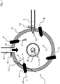
- Figure 1 shows a sectional view of a spiral jet mill (1), having a regrind feed (2) through which the regrind (10) is guided into the process space (3).
- the dosing that is to say the feeding of the ground material (10), takes place via a dosing unit (not shown), for example a rotary valve, or a pump device.
- Grinding nozzles (4) which are positioned at a suitable distance from one another, protrude into the process space (3). This suitable distance varies depending on the number of grinding nozzles (4) and should be selected so that the grinding nozzles (4) are evenly distributed on the circular path that describes the housing (5) that surrounds the process space (3), in the example of Figure 1 So the grinding nozzles (4) are each offset by 90 ° and their respective longitudinal axis (41) close with a Area of the respective grinding nozzle attachment in the housing (5) tangent (13) an angle alpha ( ⁇ ) which should be in the range 10 ° and 60 °. Regarding the application, the grinding nozzles (4) can also be arranged irregularly on the housing (5).
- the grinding nozzles (4) feed the grinding fluid (6) to the process space (3).
- This grinding fluid (6) serves to stress and crush the output grinding stock (10).
- the parameters such as pressure, quantity, temperature and spray angle for the grinding fluid (6) must be adjusted.
- gases can be used as grinding fluid (6), in particular protective gases such as argon and helium and nitrogen.
- the fine material outlet (7) is located in the middle of the process space (3), this leads particles through the cover or the bottom of the housing (5) out of the process space (3).
- the particles are removed through the fine material outlet (7), which have achieved the necessary fineness through grinding in the process space (3), that is to say the ground portions of the ground material (11).
- a sifter wheel (8) is positioned around the fine material outlet (7) so that only particles with the required fineness can leave the process space (3).
- the classifier wheel (8) rotates and is operated at a variable speed. The necessary fineness for the ground portions of the ground material (11) can thus be set.
- a particle that is too large wants to pass the rotating classifier wheel (8), it is thrown back into the process chamber (3) by the safety wheel (8) and subjected to a new load. If the particle is ground finely enough, it has a sufficiently small particle or grain size and it can leave the process chamber (3) through the fine material drain (7) with the fluid flow of the ground portions of the ground material (11).
- the regrind feed (2) is closed in relation to the process space (3).
- the discharge nozzle (9) opens at the same time or with a defined time offset. This is closed during the grinding process by a closure element (14), for example a flap, or a slide relative to the process space (3).
- This closure element (14) can be positioned as desired in the discharge nozzle (9), for example the closure element (14) can lie flush against the outer shell of the housing (5), or can be attached within the housing (5) and terminate flush with the process space (3) , Due to the overpressure or underpressure in the process room (3) of -500 mbar (g) to +600 mbar (g), all the particles in the process room (3) are now flushed out of the process room (3) via the discharge nozzle (9).
- the discharge nozzle (9 ) After a period of, for example, 1 to 60 seconds or a message from a sensor that monitors the degree of filling in the process room (3) and thus checks whether all parts of the millbase (12) that are difficult or impossible to grind have been discharged from the process room, the discharge nozzle (9 ), closed again by means of the closure element (14). The regrind (2) is then opened or started again and the grinding process is continued.
Landscapes
- Engineering & Computer Science (AREA)
- Food Science & Technology (AREA)
- Disintegrating Or Milling (AREA)
- Crushing And Grinding (AREA)
Priority Applications (1)
| Application Number | Priority Date | Filing Date | Title |
|---|---|---|---|
| SI201930679T SI3613508T1 (sl) | 2018-08-23 | 2019-08-07 | Postopek odstranjevanja slabo mlevnih delcev iz spiralnega mešalnika |
Applications Claiming Priority (1)
| Application Number | Priority Date | Filing Date | Title |
|---|---|---|---|
| DE102018120596.1A DE102018120596A1 (de) | 2018-08-23 | 2018-08-23 | Verfahren und Vorrichtung zur Ausschleusung schwer mahlbarer Partikel aus einer Spiralstrahlmühle |
Publications (2)
| Publication Number | Publication Date |
|---|---|
| EP3613508A1 true EP3613508A1 (fr) | 2020-02-26 |
| EP3613508B1 EP3613508B1 (fr) | 2023-09-27 |
Family
ID=67551233
Family Applications (1)
| Application Number | Title | Priority Date | Filing Date |
|---|---|---|---|
| EP19190424.2A Active EP3613508B1 (fr) | 2018-08-23 | 2019-08-07 | Procédé de décharge des particules difficilement broyables d'un désintégrateur à jet hélicoïdal |
Country Status (13)
| Country | Link |
|---|---|
| US (1) | US11235337B2 (fr) |
| EP (1) | EP3613508B1 (fr) |
| JP (1) | JP6934491B2 (fr) |
| KR (1) | KR102277738B1 (fr) |
| CN (1) | CN110856830B (fr) |
| DE (1) | DE102018120596A1 (fr) |
| DK (1) | DK3613508T3 (fr) |
| ES (1) | ES2966925T3 (fr) |
| FI (1) | FI3613508T3 (fr) |
| LT (1) | LT3613508T (fr) |
| PL (1) | PL3613508T3 (fr) |
| RU (1) | RU2732837C1 (fr) |
| SI (1) | SI3613508T1 (fr) |
Cited By (1)
| Publication number | Priority date | Publication date | Assignee | Title |
|---|---|---|---|---|
| EP4088818A1 (fr) | 2021-05-14 | 2022-11-16 | LANXESS Deutschland GmbH | Désintégrateur à jet hélicoïdal et procédé de broyage des produits à broyer dans un désintégrateur à jet hélicoïdal |
Citations (3)
| Publication number | Priority date | Publication date | Assignee | Title |
|---|---|---|---|---|
| DE4431534A1 (de) | 1994-02-10 | 1995-08-17 | Nied Roland | Maschine zum Einwirken auf zermahl- und klassierbares Gut |
| WO1996001694A1 (fr) * | 1994-07-11 | 1996-01-25 | Pmt Gesteinsvermahlungstechnik Powder Maker Technologies Gmbh | Desintegrateur a jet helicoidal |
| EP1808231A1 (fr) * | 2006-01-14 | 2007-07-18 | Josef Fischer | Séparation de minéraux |
Family Cites Families (23)
| Publication number | Priority date | Publication date | Assignee | Title |
|---|---|---|---|---|
| US3425638A (en) * | 1965-10-04 | 1969-02-04 | Grace W R & Co | Fluid energy mill |
| US3602439A (en) * | 1969-07-25 | 1971-08-31 | Nippon Pneumatic Mfg | Pneumatic mill for extra-fine powder |
| DE2063635C3 (de) * | 1970-12-30 | 1980-01-03 | Daikin Kogyo Co. Ltd., Tokio | Verfahren zur Herstellung eines nicht faserigen ultrafeinen Polytetrafluoräthylen-Formpulvers |
| US3726484A (en) * | 1971-10-15 | 1973-04-10 | Du Pont | Stepped fluid energy mill |
| US4502641A (en) * | 1981-04-29 | 1985-03-05 | E. I. Du Pont De Nemours And Company | Fluid energy mill with differential pressure means |
| JPH0824702A (ja) * | 1994-07-20 | 1996-01-30 | Hosokawa Micron Corp | 原液から微粉末を製造する方法及びその装置 |
| JP3831102B2 (ja) * | 1997-12-25 | 2006-10-11 | 日本ニューマチック工業株式会社 | ジェット粉砕機 |
| RU2199397C2 (ru) * | 2000-11-16 | 2003-02-27 | Белгородская государственная технологическая академия строительных материалов | Устройство для вихревого измельчения материалов |
| JP4205888B2 (ja) * | 2001-12-20 | 2009-01-07 | ホソカワミクロン株式会社 | 粉体処理装置および粉体処理方法 |
| KR20040073116A (ko) * | 2003-02-13 | 2004-08-19 | (주)디자인메카 | 복수개의 분쇄물 출구와 와류발생기를 갖는 유체에너지밀 분쇄장치 및 분쇄방법 |
| EP1775024A1 (fr) * | 2004-07-09 | 2007-04-18 | Sunrex Kogyo Co.,Ltd. | Broyeur à jet |
| DE102006017472A1 (de) * | 2006-04-13 | 2007-10-18 | Nied, Roland, Dr. Ing. | Verfahren zur Erzeugung feinster Partikel mittels einer Strahlmühle |
| BRPI0814106A2 (pt) * | 2007-07-09 | 2015-02-03 | Unimin Corp | Pó de sienito de nefelina com tamanho de partícula controlado e método de produzir o mesmo |
| KR101063545B1 (ko) * | 2008-11-11 | 2011-09-07 | (주) 알앤에이 | 분급장치 |
| CN102430380B (zh) * | 2010-09-29 | 2014-08-06 | 张小丁 | 流体激波反应器 |
| US9914132B2 (en) * | 2011-09-15 | 2018-03-13 | Michael J. Pilgrim | Devices, systems, and methods for processing heterogeneous materials |
| US9931639B2 (en) * | 2014-01-16 | 2018-04-03 | Cold Jet, Llc | Blast media fragmenter |
| EP3307440A1 (fr) * | 2015-06-15 | 2018-04-18 | NETZSCH Trockenmahltechnik GmbH | Procédé de fragmentation d'un produit à broyer et broyeur associé |
| DE102015118858B3 (de) * | 2015-11-04 | 2017-02-09 | Netzsch-Feinmahltechnik Gmbh | Zerkleinerungsvorrichtung und Verfahren zum Zerkleinern von Rohstoffen |
| CN205236215U (zh) * | 2015-12-31 | 2016-05-18 | 江苏博迁新材料有限公司 | 一种高速导流气旋打散分级机 |
| IT201600098452A1 (it) * | 2016-09-30 | 2018-03-30 | Micro Macinazione Sa | Apparecchiatura per la micronizzazione di materiale polveroso con capacita’ di prevenire incrostazioni |
| CN106955774A (zh) * | 2017-05-10 | 2017-07-18 | 成都赋阳技术开发有限公司 | 一种采用气流冲击方式进行分料的超微粉碎机 |
| CN207169926U (zh) * | 2017-08-04 | 2018-04-03 | 池州特乃博先进材料有限公司 | 一种流化床气流粉碎机 |
-
2018
- 2018-08-23 DE DE102018120596.1A patent/DE102018120596A1/de active Pending
-
2019
- 2019-07-04 JP JP2019125488A patent/JP6934491B2/ja active Active
- 2019-08-07 LT LTEP19190424.2T patent/LT3613508T/lt unknown
- 2019-08-07 EP EP19190424.2A patent/EP3613508B1/fr active Active
- 2019-08-07 PL PL19190424.2T patent/PL3613508T3/pl unknown
- 2019-08-07 SI SI201930679T patent/SI3613508T1/sl unknown
- 2019-08-07 FI FIEP19190424.2T patent/FI3613508T3/fi active
- 2019-08-07 ES ES19190424T patent/ES2966925T3/es active Active
- 2019-08-07 DK DK19190424.2T patent/DK3613508T3/da active
- 2019-08-09 CN CN201910735624.0A patent/CN110856830B/zh active Active
- 2019-08-14 RU RU2019125652A patent/RU2732837C1/ru active
- 2019-08-19 US US16/544,163 patent/US11235337B2/en active Active
- 2019-08-20 KR KR1020190101613A patent/KR102277738B1/ko active IP Right Grant
Patent Citations (3)
| Publication number | Priority date | Publication date | Assignee | Title |
|---|---|---|---|---|
| DE4431534A1 (de) | 1994-02-10 | 1995-08-17 | Nied Roland | Maschine zum Einwirken auf zermahl- und klassierbares Gut |
| WO1996001694A1 (fr) * | 1994-07-11 | 1996-01-25 | Pmt Gesteinsvermahlungstechnik Powder Maker Technologies Gmbh | Desintegrateur a jet helicoidal |
| EP1808231A1 (fr) * | 2006-01-14 | 2007-07-18 | Josef Fischer | Séparation de minéraux |
Cited By (2)
| Publication number | Priority date | Publication date | Assignee | Title |
|---|---|---|---|---|
| EP4088818A1 (fr) | 2021-05-14 | 2022-11-16 | LANXESS Deutschland GmbH | Désintégrateur à jet hélicoïdal et procédé de broyage des produits à broyer dans un désintégrateur à jet hélicoïdal |
| WO2022238573A1 (fr) | 2021-05-14 | 2022-11-17 | Lanxess Deutschland Gmbh | Broyeur à jet en spirale et procédé pour broyer des matières à broyer dans un broyeur à jet en spirale |
Also Published As
| Publication number | Publication date |
|---|---|
| CN110856830B (zh) | 2022-04-15 |
| DK3613508T3 (da) | 2023-12-18 |
| JP2020028877A (ja) | 2020-02-27 |
| EP3613508B1 (fr) | 2023-09-27 |
| JP6934491B2 (ja) | 2021-09-15 |
| SI3613508T1 (sl) | 2024-03-29 |
| KR20200023208A (ko) | 2020-03-04 |
| ES2966925T3 (es) | 2024-04-25 |
| LT3613508T (lt) | 2023-12-27 |
| US11235337B2 (en) | 2022-02-01 |
| DE102018120596A1 (de) | 2020-02-27 |
| CN110856830A (zh) | 2020-03-03 |
| US20200061631A1 (en) | 2020-02-27 |
| KR102277738B1 (ko) | 2021-07-16 |
| PL3613508T3 (pl) | 2024-03-04 |
| FI3613508T3 (fi) | 2023-12-19 |
| RU2732837C1 (ru) | 2020-09-23 |
Similar Documents
| Publication | Publication Date | Title |
|---|---|---|
| EP1536892B1 (fr) | Dispositif de broyage | |
| EP2004329B1 (fr) | Procédé de génération de particules très fines au moyen d'un pulvérisateur à jet | |
| EP3291915B1 (fr) | Broyeuse comprenant un système de rotor et procédé servant au broyage d'un produit chargé | |
| DE3311433A1 (de) | Klassieren von mahlgut von vertikalen rollenmuehlen | |
| EP0374491B1 (fr) | Séparateur pneumatique | |
| DE102014117188B3 (de) | Verfahren zum Regulieren der Förderleistung eines Rotors einer Trenneinrichtung einer Rührwerkskugelmühle und Rührwerkskugelmühle zum Zerkleinern von Mahlgut | |
| WO2016165917A1 (fr) | Dispositif et procédé de mélange, en particulier de dispersion | |
| DE3140294C2 (de) | Verfahren und Vorrichtung zum Trennen eines Gutgemisches in Komponenten unterschiedlicher Mahlbarkeit | |
| DE4005323A1 (de) | Verfahren und mahlanlage zur zweistufigen zerkleinerung von sproedem mahlgut | |
| EP1080786A1 (fr) | Procédé, dispositif et système pour broyeur à jet à lit fluidisé | |
| DE102006023193A1 (de) | Verfahren zur Erzeugung feinster Partikel mittels einer Strahlmühle | |
| EP1237656A1 (fr) | Dispositif de broyage d'un materiau a broyer | |
| EP3613508B1 (fr) | Procédé de décharge des particules difficilement broyables d'un désintégrateur à jet hélicoïdal | |
| EP3895806A1 (fr) | Dispositif et procédé de broyage de matières solides | |
| EP1640070B1 (fr) | Installation et procédure de fragmentation du produit de passage à la meule | |
| DE3844380C1 (en) | Agitator mill with separating device in a rotating cage | |
| DE3609229A1 (de) | Verfahren und anlage zur zerkleinerung von sproedem mahlgut | |
| EP1448303B1 (fr) | Tube broyeur et procede pour broyer des produits a moudre en morceaux | |
| DE3138259C2 (fr) | ||
| DE3730597C2 (de) | Strahlmühle | |
| AT391752B (de) | Mahltrocknungsanlage mit vorzerkleinerung | |
| DE1253562B (de) | Prall- und Schaelmuehle mit mindestens zwei um eine lotrechte Achse umlaufenden Schleuderraedern | |
| DE4431534B4 (de) | Maschine zur Einwirkung auf zerkleinerbares und klassierbares Rohgut, sowie Verfahren zum Betrieb der Maschine | |
| EP3476486A1 (fr) | Dispositif et procédé de broyage de granules en vrac | |
| AT338598B (de) | Vorrichtung zum mahlen von beliebigem mahlgut |
Legal Events
| Date | Code | Title | Description |
|---|---|---|---|
| PUAI | Public reference made under article 153(3) epc to a published international application that has entered the european phase |
Free format text: ORIGINAL CODE: 0009012 |
|
| STAA | Information on the status of an ep patent application or granted ep patent |
Free format text: STATUS: THE APPLICATION HAS BEEN PUBLISHED |
|
| AK | Designated contracting states |
Kind code of ref document: A1 Designated state(s): AL AT BE BG CH CY CZ DE DK EE ES FI FR GB GR HR HU IE IS IT LI LT LU LV MC MK MT NL NO PL PT RO RS SE SI SK SM TR |
|
| AX | Request for extension of the european patent |
Extension state: BA ME |
|
| STAA | Information on the status of an ep patent application or granted ep patent |
Free format text: STATUS: REQUEST FOR EXAMINATION WAS MADE |
|
| 17P | Request for examination filed |
Effective date: 20200826 |
|
| RBV | Designated contracting states (corrected) |
Designated state(s): AL AT BE BG CH CY CZ DE DK EE ES FI FR GB GR HR HU IE IS IT LI LT LU LV MC MK MT NL NO PL PT RO RS SE SI SK SM TR |
|
| GRAP | Despatch of communication of intention to grant a patent |
Free format text: ORIGINAL CODE: EPIDOSNIGR1 |
|
| STAA | Information on the status of an ep patent application or granted ep patent |
Free format text: STATUS: GRANT OF PATENT IS INTENDED |
|
| RIC1 | Information provided on ipc code assigned before grant |
Ipc: B02C 25/00 20060101ALI20230223BHEP Ipc: B02C 19/06 20060101AFI20230223BHEP |
|
| INTG | Intention to grant announced |
Effective date: 20230320 |
|
| GRAS | Grant fee paid |
Free format text: ORIGINAL CODE: EPIDOSNIGR3 |
|
| GRAA | (expected) grant |
Free format text: ORIGINAL CODE: 0009210 |
|
| STAA | Information on the status of an ep patent application or granted ep patent |
Free format text: STATUS: THE PATENT HAS BEEN GRANTED |
|
| AK | Designated contracting states |
Kind code of ref document: B1 Designated state(s): AL AT BE BG CH CY CZ DE DK EE ES FI FR GB GR HR HU IE IS IT LI LT LU LV MC MK MT NL NO PL PT RO RS SE SI SK SM TR |
|
| REG | Reference to a national code |
Ref country code: GB Ref legal event code: FG4D Free format text: NOT ENGLISH |
|
| REG | Reference to a national code |
Ref country code: CH Ref legal event code: EP |
|
| REG | Reference to a national code |
Ref country code: DE Ref legal event code: R096 Ref document number: 502019009471 Country of ref document: DE |
|
| REG | Reference to a national code |
Ref country code: IE Ref legal event code: FG4D Free format text: LANGUAGE OF EP DOCUMENT: GERMAN |
|
| REG | Reference to a national code |
Ref country code: DK Ref legal event code: T3 Effective date: 20231214 |
|
| REG | Reference to a national code |
Ref country code: SE Ref legal event code: TRGR |
|
| REG | Reference to a national code |
Ref country code: NL Ref legal event code: FP |
|
| PG25 | Lapsed in a contracting state [announced via postgrant information from national office to epo] |
Ref country code: GR Free format text: LAPSE BECAUSE OF FAILURE TO SUBMIT A TRANSLATION OF THE DESCRIPTION OR TO PAY THE FEE WITHIN THE PRESCRIBED TIME-LIMIT Effective date: 20231228 |
|
| PG25 | Lapsed in a contracting state [announced via postgrant information from national office to epo] |
Ref country code: RS Free format text: LAPSE BECAUSE OF FAILURE TO SUBMIT A TRANSLATION OF THE DESCRIPTION OR TO PAY THE FEE WITHIN THE PRESCRIBED TIME-LIMIT Effective date: 20230927 Ref country code: HR Free format text: LAPSE BECAUSE OF FAILURE TO SUBMIT A TRANSLATION OF THE DESCRIPTION OR TO PAY THE FEE WITHIN THE PRESCRIBED TIME-LIMIT Effective date: 20230927 Ref country code: GR Free format text: LAPSE BECAUSE OF FAILURE TO SUBMIT A TRANSLATION OF THE DESCRIPTION OR TO PAY THE FEE WITHIN THE PRESCRIBED TIME-LIMIT Effective date: 20231228 |
|
| REG | Reference to a national code |
Ref country code: NO Ref legal event code: T2 Effective date: 20230927 |
|
| REG | Reference to a national code |
Ref country code: EE Ref legal event code: FG4A Ref document number: E023894 Country of ref document: EE Effective date: 20231214 |
|
| PG25 | Lapsed in a contracting state [announced via postgrant information from national office to epo] |
Ref country code: IS Free format text: LAPSE BECAUSE OF FAILURE TO SUBMIT A TRANSLATION OF THE DESCRIPTION OR TO PAY THE FEE WITHIN THE PRESCRIBED TIME-LIMIT Effective date: 20240127 |
|
| REG | Reference to a national code |
Ref country code: ES Ref legal event code: FG2A Ref document number: 2966925 Country of ref document: ES Kind code of ref document: T3 Effective date: 20240425 |
|
| PG25 | Lapsed in a contracting state [announced via postgrant information from national office to epo] |
Ref country code: SM Free format text: LAPSE BECAUSE OF FAILURE TO SUBMIT A TRANSLATION OF THE DESCRIPTION OR TO PAY THE FEE WITHIN THE PRESCRIBED TIME-LIMIT Effective date: 20230927 Ref country code: RO Free format text: LAPSE BECAUSE OF FAILURE TO SUBMIT A TRANSLATION OF THE DESCRIPTION OR TO PAY THE FEE WITHIN THE PRESCRIBED TIME-LIMIT Effective date: 20230927 Ref country code: IS Free format text: LAPSE BECAUSE OF FAILURE TO SUBMIT A TRANSLATION OF THE DESCRIPTION OR TO PAY THE FEE WITHIN THE PRESCRIBED TIME-LIMIT Effective date: 20240127 Ref country code: CZ Free format text: LAPSE BECAUSE OF FAILURE TO SUBMIT A TRANSLATION OF THE DESCRIPTION OR TO PAY THE FEE WITHIN THE PRESCRIBED TIME-LIMIT Effective date: 20230927 Ref country code: PT Free format text: LAPSE BECAUSE OF FAILURE TO SUBMIT A TRANSLATION OF THE DESCRIPTION OR TO PAY THE FEE WITHIN THE PRESCRIBED TIME-LIMIT Effective date: 20240129 Ref country code: SK Free format text: LAPSE BECAUSE OF FAILURE TO SUBMIT A TRANSLATION OF THE DESCRIPTION OR TO PAY THE FEE WITHIN THE PRESCRIBED TIME-LIMIT Effective date: 20230927 |