EP3610996A1 - Système de robot et procédé d'actionnement d'un tel système de robot - Google Patents
Système de robot et procédé d'actionnement d'un tel système de robot Download PDFInfo
- Publication number
- EP3610996A1 EP3610996A1 EP18784839.5A EP18784839A EP3610996A1 EP 3610996 A1 EP3610996 A1 EP 3610996A1 EP 18784839 A EP18784839 A EP 18784839A EP 3610996 A1 EP3610996 A1 EP 3610996A1
- Authority
- EP
- European Patent Office
- Prior art keywords
- robot
- information
- display unit
- type display
- transparent type
- Prior art date
- Legal status (The legal status is an assumption and is not a legal conclusion. Google has not performed a legal analysis and makes no representation as to the accuracy of the status listed.)
- Pending
Links
- 238000000034 method Methods 0.000 title claims abstract description 58
- 230000008569 process Effects 0.000 claims abstract description 35
- 230000005856 abnormality Effects 0.000 claims description 18
- 230000001133 acceleration Effects 0.000 claims description 17
- 238000001514 detection method Methods 0.000 claims 1
- 230000004048 modification Effects 0.000 description 43
- 238000012986 modification Methods 0.000 description 43
- 239000012636 effector Substances 0.000 description 26
- 230000000694 effects Effects 0.000 description 18
- 238000012937 correction Methods 0.000 description 11
- 230000006870 function Effects 0.000 description 9
- 238000006073 displacement reaction Methods 0.000 description 8
- NJPPVKZQTLUDBO-UHFFFAOYSA-N novaluron Chemical compound C1=C(Cl)C(OC(F)(F)C(OC(F)(F)F)F)=CC=C1NC(=O)NC(=O)C1=C(F)C=CC=C1F NJPPVKZQTLUDBO-UHFFFAOYSA-N 0.000 description 8
- 238000004519 manufacturing process Methods 0.000 description 5
- 238000010586 diagram Methods 0.000 description 4
- 230000002093 peripheral effect Effects 0.000 description 4
- 230000008859 change Effects 0.000 description 3
- 238000002474 experimental method Methods 0.000 description 3
- 230000006872 improvement Effects 0.000 description 3
- 230000003190 augmentative effect Effects 0.000 description 2
- 238000006243 chemical reaction Methods 0.000 description 2
- 238000012888 cubic function Methods 0.000 description 2
- 230000002452 interceptive effect Effects 0.000 description 2
- 239000007788 liquid Substances 0.000 description 2
- 238000012545 processing Methods 0.000 description 2
- 238000012887 quadratic function Methods 0.000 description 2
- 230000004044 response Effects 0.000 description 2
- 230000015541 sensory perception of touch Effects 0.000 description 2
- 238000013459 approach Methods 0.000 description 1
- 230000008878 coupling Effects 0.000 description 1
- 238000010168 coupling process Methods 0.000 description 1
- 238000005859 coupling reaction Methods 0.000 description 1
- 230000003247 decreasing effect Effects 0.000 description 1
- 239000011521 glass Substances 0.000 description 1
- 238000010422 painting Methods 0.000 description 1
- 239000000843 powder Substances 0.000 description 1
Images


Classifications
-
- B—PERFORMING OPERATIONS; TRANSPORTING
- B25—HAND TOOLS; PORTABLE POWER-DRIVEN TOOLS; MANIPULATORS
- B25J—MANIPULATORS; CHAMBERS PROVIDED WITH MANIPULATION DEVICES
- B25J13/00—Controls for manipulators
-
- B—PERFORMING OPERATIONS; TRANSPORTING
- B25—HAND TOOLS; PORTABLE POWER-DRIVEN TOOLS; MANIPULATORS
- B25J—MANIPULATORS; CHAMBERS PROVIDED WITH MANIPULATION DEVICES
- B25J13/00—Controls for manipulators
- B25J13/06—Control stands, e.g. consoles, switchboards
-
- B—PERFORMING OPERATIONS; TRANSPORTING
- B25—HAND TOOLS; PORTABLE POWER-DRIVEN TOOLS; MANIPULATORS
- B25J—MANIPULATORS; CHAMBERS PROVIDED WITH MANIPULATION DEVICES
- B25J19/00—Accessories fitted to manipulators, e.g. for monitoring, for viewing; Safety devices combined with or specially adapted for use in connection with manipulators
- B25J19/02—Sensing devices
- B25J19/021—Optical sensing devices
- B25J19/023—Optical sensing devices including video camera means
-
- B—PERFORMING OPERATIONS; TRANSPORTING
- B25—HAND TOOLS; PORTABLE POWER-DRIVEN TOOLS; MANIPULATORS
- B25J—MANIPULATORS; CHAMBERS PROVIDED WITH MANIPULATION DEVICES
- B25J19/00—Accessories fitted to manipulators, e.g. for monitoring, for viewing; Safety devices combined with or specially adapted for use in connection with manipulators
- B25J19/02—Sensing devices
- B25J19/04—Viewing devices
-
- G—PHYSICS
- G05—CONTROLLING; REGULATING
- G05B—CONTROL OR REGULATING SYSTEMS IN GENERAL; FUNCTIONAL ELEMENTS OF SUCH SYSTEMS; MONITORING OR TESTING ARRANGEMENTS FOR SUCH SYSTEMS OR ELEMENTS
- G05B19/00—Programme-control systems
- G05B19/02—Programme-control systems electric
- G05B19/418—Total factory control, i.e. centrally controlling a plurality of machines, e.g. direct or distributed numerical control [DNC], flexible manufacturing systems [FMS], integrated manufacturing systems [IMS] or computer integrated manufacturing [CIM]
- G05B19/41865—Total factory control, i.e. centrally controlling a plurality of machines, e.g. direct or distributed numerical control [DNC], flexible manufacturing systems [FMS], integrated manufacturing systems [IMS] or computer integrated manufacturing [CIM] characterised by job scheduling, process planning, material flow
-
- G—PHYSICS
- G06—COMPUTING; CALCULATING OR COUNTING
- G06F—ELECTRIC DIGITAL DATA PROCESSING
- G06F3/00—Input arrangements for transferring data to be processed into a form capable of being handled by the computer; Output arrangements for transferring data from processing unit to output unit, e.g. interface arrangements
- G06F3/01—Input arrangements or combined input and output arrangements for interaction between user and computer
- G06F3/011—Arrangements for interaction with the human body, e.g. for user immersion in virtual reality
-
- G—PHYSICS
- G06—COMPUTING; CALCULATING OR COUNTING
- G06F—ELECTRIC DIGITAL DATA PROCESSING
- G06F3/00—Input arrangements for transferring data to be processed into a form capable of being handled by the computer; Output arrangements for transferring data from processing unit to output unit, e.g. interface arrangements
- G06F3/01—Input arrangements or combined input and output arrangements for interaction between user and computer
- G06F3/03—Arrangements for converting the position or the displacement of a member into a coded form
- G06F3/033—Pointing devices displaced or positioned by the user, e.g. mice, trackballs, pens or joysticks; Accessories therefor
- G06F3/0346—Pointing devices displaced or positioned by the user, e.g. mice, trackballs, pens or joysticks; Accessories therefor with detection of the device orientation or free movement in a 3D space, e.g. 3D mice, 6-DOF [six degrees of freedom] pointers using gyroscopes, accelerometers or tilt-sensors
-
- G—PHYSICS
- G02—OPTICS
- G02B—OPTICAL ELEMENTS, SYSTEMS OR APPARATUS
- G02B27/00—Optical systems or apparatus not provided for by any of the groups G02B1/00 - G02B26/00, G02B30/00
- G02B27/01—Head-up displays
- G02B27/0101—Head-up displays characterised by optical features
- G02B2027/0138—Head-up displays characterised by optical features comprising image capture systems, e.g. camera
-
- G—PHYSICS
- G02—OPTICS
- G02B—OPTICAL ELEMENTS, SYSTEMS OR APPARATUS
- G02B27/00—Optical systems or apparatus not provided for by any of the groups G02B1/00 - G02B26/00, G02B30/00
- G02B27/01—Head-up displays
- G02B27/017—Head mounted
- G02B2027/0178—Eyeglass type
-
- G—PHYSICS
- G05—CONTROLLING; REGULATING
- G05B—CONTROL OR REGULATING SYSTEMS IN GENERAL; FUNCTIONAL ELEMENTS OF SUCH SYSTEMS; MONITORING OR TESTING ARRANGEMENTS FOR SUCH SYSTEMS OR ELEMENTS
- G05B2219/00—Program-control systems
- G05B2219/30—Nc systems
- G05B2219/32—Operator till task planning
- G05B2219/32128—Gui graphical user interface
-
- G—PHYSICS
- G05—CONTROLLING; REGULATING
- G05B—CONTROL OR REGULATING SYSTEMS IN GENERAL; FUNCTIONAL ELEMENTS OF SUCH SYSTEMS; MONITORING OR TESTING ARRANGEMENTS FOR SUCH SYSTEMS OR ELEMENTS
- G05B2219/00—Program-control systems
- G05B2219/30—Nc systems
- G05B2219/39—Robotics, robotics to robotics hand
- G05B2219/39001—Robot, manipulator control
Definitions
- the present disclosure relates to a robot system and a method of operating the same.
- Patent Document 1 An interactive operating system in which an operator teaches a robot an operation using a robot teaching device which is operated by the operator is known (for example, refer to Patent Document 1).
- Patent Document 1 describes that sensed information (image information) by a sensed information detector disposed at the robot and actually sensed information (peripheral information) sensed by the operator himself are constantly and duplicatedly sensed and, thus, the robot can be operated while constantly paying attention to the environment around the operator.
- the present disclosure is made in view of solving the problem described above, and is to provide a robot system and a method of operating the same, capable of reducing an operator's burden and improving work efficiency.
- a robot system includes a user interface configured to receive an operational instruction from an operator, a robot installed in a workspace and configured to perform a series of works comprised of a plurality of processes, a sensor installed in the workspace, a transparent type display unit configured so that the operator is visible of a physical real world and configured to display an image screen, and a control device.
- the control device displays on the transparent type display unit, when the robot is operated by the user interface, first information that is information detected by the sensor, as the image screen.
- the first information that is information detected by the sensor when required, it can be displayed on the transparent type display unit.
- the operator's burden can be reduced and the work efficiency can be improved.
- the robot system includes a user interface configured to receive an operational instruction from an operator, a robot installed in a workspace and configured to perform a series of works comprised of a plurality of processes, a sensor installed in the workspace, and a transparent type display unit configured so that the operator is visible of a physical real world and configured to display an image screen.
- the method includes (A) displaying on the transparent type display unit, when the robot is operated by the user interface, first information that is information detected by the sensor, as the image screen.
- the first information that is information detected by the sensor when required, it can be displayed on the transparent type display unit.
- the operator's burden can be reduced and the work efficiency can be improved.
- the operator's burden can be reduced and the work efficiency can be improved.
- a robot system includes a user interface which receives an operational instruction from an operator, a robot which is installed in a workspace and performs a series of works comprised of a plurality of processes, a sensor installed in the workspace, a transparent type display unit which is configured so that an operator is visible of a physical real world and is configured to display an image screen, and a control device.
- the control device displays, as the image screen, first information which is information detected by the sensor on the transparent type display unit, when the robot is operated by the user interface.
- the senor may be disposed at a tip-end part of the robot.
- the sensor may be comprised of a camera.
- the transparent type display unit may be configured to be wearable by the operator.
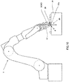
- Fig. 1 is a block diagram illustrating an outline configuration of the robot system according to Embodiment 1.
- Fig. 2 is a schematic view illustrating one example of the transparent type display unit of the robot system illustrated in Fig. 1 .
- the robot system 100 includes a robot 1, a user interface 2, a sensor 3, a control device 4, a storage device 5, and a transparent type display unit 6.
- the robot system 100 is configured so that the robot 1 operates by the operator operating the user interface 2.
- the robot system 100 according to Embodiment 1 is configured so that, when the operator operates the user interface 2, the control device 4 displays first information which is information detected by the sensor 3 on the transparent type display unit 6 as an image screen.
- the robot 1 is installed in a workspace, and is configured to perform a series of works comprised of a plurality of processes.
- the series of works comprised of a plurality of processes include works, such as assembling of a component to a product, painting, etc.
- the robot 1 according to Embodiment 1 is an articulated robot used at a production plant which assembles electric and/or electronic components etc. to manufacture the product in a line production system or a cell production system, is disposed along a workbench provided in this production plant, and is capable of performing at least one of works, such as transferring, assembling or relocating of a component, and a posture conversion, for the workpiece on the workbench.
- the embodiment of the robot 1 is not limited to the above applications, and is widely applicable to articulated robots, regardless of the horizontal articulated type and the vertical articulated type.
- Fig. 3 is a schematic view illustrating an outline configuration of the robot in the robot system illustrated in Fig. 1 .
- the robot 1 is an articulated robotic arm having a serially coupling body of a plurality of links (here, a first link 11a to a sixth link 11 f), a plurality of joints (here, a first joint JT1 to a sixth joint JT6), and a pedestal 15 which supports the links and joints.
- a serially coupling body of a plurality of links here, a first link 11a to a sixth link 11 f
- a plurality of joints here, a first joint JT1 to a sixth joint JT6
- a pedestal 15 which supports the links and joints.
- the pedestal 15 and a base-end part of the first link 11a are coupled to each other so as to be rotatable on an axis extending in the up-and-down direction.
- a tip-end part of the first link 11a and a base-end part of the second link 11b are coupled to each other so as to be rotatable on an axis extending in the horizontal direction.
- a tip-end part of the second link 11b and a base-end part of the third link 11c are coupled to each other so as to be rotatable on an axis extending in the horizontal direction.
- a tip-end part of the third link 11c and a base-end part of the fourth link 11d are coupled to each other so as to be rotatable on an axis extending in the longitudinal direction of the fourth link 11d.
- a tip-end part of the fourth link 11d and a base-end part of the fifth link 11e are coupled to each other so as to be rotatable on an axis perpendicular to the longitudinal direction of the fourth link 11d.
- a tip-end part of the fifth link 11e and a base-end part of the sixth link 11f are coupled to each other so as to be rotatable in a twisting manner.
- a mechanical interface is provided to a tip-end part of the sixth link 11f.
- An end effector 12 corresponding to the type of the work is detachably attached to the mechanical interface.
- a camera 3A which constitutes the sensor 3 is provided to the mechanical interface (a tip-end part of the robot 1). The camera 3A is configured to output captured image information to the control device 4.
- a drive motor (not illustrated) as one example of an actuator which relatively rotates two members coupled by each joint is provided to each of the first joint JT1 to the sixth joint JT6.
- the drive motor may be, for example, a servo motor which is servo-controlled by the control device 4.
- a rotation sensor which detects a rotational position of the drive motor, and a current sensor which detects current for controlling the rotation of the drive motor are provided to each of the first joint JT1 to the sixth joint JT6 (none of them is illustrated).
- the rotation sensor may be, for example, an encoder.
- the user interface 2 is a device which is installed outside the workspace and receives an operational instruction from the operator.
- the user interface 2 may include, for example, a master arm, a joystick, or a tablet.
- the user interface 2 may be provided with a regulator for adjusting an operating speed of the robot 1.
- the storage device (memory) 5 is a readable and writable recording medium, and stores a task program 51 and operation sequence information 52 of the robot system 100. Note that, in the robot system 100 according to Embodiment 1, although the storage device 5 is provided separately from the control device 4, it may be provided integrally with the control device 4.
- the task program 51 is created, for example, by the operator performing teaching by using the user interface 2 comprised of a teaching pendant etc., and it is stored in the storage device 5 so as to be associated with identification information and a task of the robot 1. Note that the task program 51 may be created as an operation flow for each work.
- the operation sequence information 52 is information related to the operation sequence which defines a series of operation processes to be carried out by the robot 1 in the workspace.
- an operating order of the work processes, and a control mode of the robot 1 are associated with each other.
- the task program for causing the robot 1 to automatically perform a work is associated with each work process.
- the operation sequence information 52 may include a program for causing the robot 1 to automatically perform the work of each work process.
- the control device 4 controls operation of the robot 1, and includes a receiver 40, a motion controller 41, and an output controller 42, as functional blocks.
- the control device 4 can be comprised of, for example, a processor (not illustrated) comprised of a microcontroller, a MPU, a PLC (Programmable Logic Controller), or a logic circuit, and a memory (not illustrated) comprised of a ROM or a RAM.
- a processor not illustrated
- MPU Microcontroller
- PLC Programmable Logic Controller
- each functional block provided to the control device 4 can be implemented by the processor of the control device 4 reading and executing the program stored in the memory or the storage device 5.
- control device 4 may be comprised of a sole control device, or may be comprised of a group of control devices which execute the control of the robot 1 (robot system 100) by a collaboration of the plurality of control devices.
- the receiver 40 receives an input signal transmitted from the outside of the control device 4.
- the input signal received by the receiver 40 may include, for example, a signal transmitted from the user interface 2, and a signal transmitted from an operational instruction part (not illustrated) other than the user interface 2.
- the motion controller 41 controls the robot 1 to operate based on the operational instruction received by the receiver 40 from the user interface 2.
- the motion controller 41 when the receiver 40 receives the operational instruction (operational signal) from the user interface 2 as the input signal, the motion controller 41 outputs the first information detected by the sensor 3 to the transparent type display unit 6 through the output controller 42, as the image screen.
- the motion controller 41 outputs the image information (first information) inputted into the receiver 40 from the camera 3A to the transparent type display unit 6 through the output controller 42, as the image screen.
- the motion controller 41 may output the image information inputted into the receiver 40 from the camera 3A, to the transparent type display unit 6 through the output controller 42, as the image screen.
- the first speed can be set beforehand, for example, by an experiment.
- the first speed may be 25 to 35% of the top speed (degree/second) of each joint of the robot 1, or may be 25 to 35% of the top speed (mm/second) of a moving speed of the robot 1 (a moving speed of the end effector 12 or a workpiece) when the robot 1 moves the workpiece.
- the moving speed of the robot 1 may be, for example, 250 to 350mm/second.
- the transparent type display unit 6 is configured so that the operator can view the physical real world, and is configured to display the image captured by the camera 3A (image information).
- the transparent type display unit 6 may be comprised of a head mounted display or glasses which the operator wears for use, and which is provided with a display part 6a for projecting the image information outputted from the output controller 42 of the control device 4.
- the transparent type display unit 6 may be comprised of a non-portable transparent display unit which is used while being placed on a desk, a floor, etc.
- the transparent type display unit 6 may be provided with a camera 6b which acquires information about the real world which is viewed by the operator.
- Fig. 4 is a flowchart illustrating one example of operation of the robot system according to Embodiment 1.
- the control device 4 determines whether the operational signal for operating the robot 1 is inputted from the user interface 2 (Step S101). In detail, the motion controller 41 of the control device 4 determines whether the operational signal is inputted into the receiver 40 from the user interface 2.
- control device 4 determines that the operational signal is not inputted from the user interface 2 (No at Step S101), it ends this program. Note that when the control device 4 ends this program, it then executes this program again, for example after 50msec.
- control device 4 determines that the operational signal is inputted from the user interface 2 (Yes at Step S101), it performs processing at Step S102.
- the control device 4 determines whether the robot 1 is to be operated at the first speed or below.
- the motion controller 41 of the control device 4 determines whether the operational signal for operating the robot 1 at the first speed or below is inputted from the user interface 2.
- control device 4 determines that the robot 1 is to be operated at a higher speed than the first speed (No at Step S102), it ends this program. Note that when the control device 4 ends this program, it executes this program again, for example, after 50msec.
- control device 4 determines that the robot 1 is to be operated at the first speed or below (Yes at Step S102), it causes the transparent type display unit 6 to output the image information inputted from the camera 3A (Step S103), and ends this program. Note that when the control device 4 ends this program, it executes this program again, for example, after 50msec.
- Figs. 5 and 6 are schematic views illustrating a field of view of the operator viewing through the transparent type display unit illustrated in Fig. 2 . Note that, as illustrated in Figs. 5 and 6 , below, as one concrete example of operation of the robot system 100 according to Embodiment 1, operation for fitting a cylindrical workpiece 20 held by the robot 1 onto a protrusion 21a provided to a pedestal 21 is described.
- the control device 4 may control the transparent type display unit 6 to display the image information imaged by the camera 3A on the display part 6a of the transparent type display unit 6, as the image screen 30.
- the control device 4 may control the transparent type display unit 6 to display the image information imaged by the camera 3A on the display part 6a of the transparent type display unit 6, as the image screen 30.
- the control device 4 may control the transparent type display unit 6 not to display the image information imaged by the camera 3A on the display part 6a of the transparent type display unit 6.
- the control device 4 may control the transparent type display unit 6 to display the image information imaged by the camera 3A on the display part 6a of the transparent type display unit 6, as the image screen 30.
- the operator can easily grasp a spatial relationship between the workpiece 20 and the protrusion 21a, and can easily operate the robot 1.
- the operator's work burden can be reduced and the operator's work efficiency can be improved.
- control device 4 may control the transparent type display unit 6 so as to acquire field-of-view information which is actually viewed by the operator from a camera provided to the transparent type display unit 6, analyze the field-of-view information, and display the image screen 30 on the field of view where the robot 1 and the pedestal 21 are not projected.
- the control device 4 sets the first information detected by the sensor 3 as the image screen 30, and displays the captured image on the transparent type display unit 6. Therefore, when the first information detected by the sensor 3 is required, it can be displayed on the transparent type display unit 6. Thus, the operator's burden can be reduced and the work efficiency can be improved.
- the operator when carrying out operation which requires positioning of the tip-end part of the robot 1 (end effector 12), such as operation for holding workpiece 20 by the robot 1, and operation for fitting the workpiece 20 onto the protrusion 21a, the operator operates the robot 1 at the first speed or below, in order to carefully operate the robot 1. Moreover, when carrying out operation which requires the positioning of the tip-end part of the robot 1 (end effector 12), the positioning is easy if there is image information near the tip-end part of the robot 1.
- the control device 4 displays the image information imaged by the camera 3A on the transparent type display unit 6, as the image screen 30, in response to the input of the operational instruction signal for operating the robot 1 at the first speed or below from the user interface 2.
- the image information imaged by the camera 3A when the image information imaged by the camera 3A is required, it can be displayed on the transparent type display unit 6. Thus, the operator's burden can be reduced and the work efficiency can be improved.
- Fig. 7 is a schematic view illustrating a field of view of the operator viewing through the transparent type display unit in a robot system of Modification 1 of Embodiment 1.
- the robot system 100 according to Modification 1 is the same in the fundamental configuration as the robot system 100 of Embodiment 1, the sensor 3 is comprised of a camera 3A, and the camera 3A is configured to image the robot 1 from above.
- the control device 4 displays the image information imaged by the camera 3A on the transparent type display unit 6, as the image screen 30.
- a robot system according to Embodiment 2 is configured so that the sensor detects at least one information of an information group comprised of vibration information, audio information, pressure information, acceleration information, inclination information, positional information, and image information.
- the robot system according to Embodiment 2 is further provided with a memory which stores a given first threshold, and when the first information detected by the sensor is the first threshold or above, the control device may display on a transparent type display unit, abnormality information which is information indicating that an abnormality has occurred.
- Fig. 8 is a schematic view illustrating a field of view of the operator viewing through the transparent type display unit in the robot system according to Embodiment 2.
- the robot 1 of the robot system 100 includes a vibration sensor 3B as the sensor 3.
- the vibration sensor 3B outputs detected vibration as the vibration information (first information) to the control device 4, if it is configured to detect vibration in a frequency band (for example, several Hz to about 1kHz) corresponding to a human tactile sense (hereinafter, referred to as "tactile sense vibration").
- a frequency band for example, several Hz to about 1kHz
- human tactile sense vibration hereinafter, referred to as "tactile sense vibration”
- the vibration sensor 3B outputs detected vibration as the audio information (first information) to the control device 4, if it is configured to detect vibration in a frequency band (for example, about 20Hz to about 20kHz) corresponding to human hearing (hereinafter, referred to as "hearing vibration").
- a frequency band for example, about 20Hz to about 20kHz
- the vibration sensor 3B is configured to detect the vibration information and/or the audio information, and output the information to the control device 4.
- control device 4 displays the vibration information and/or the audio information acquired from the vibration sensor 3B on the transparent type display unit 6, as the image screen 30.
- the control device 4 displays a screen indicative of respective volumes illustrated by bars corresponding to frequency bands (2Hz, 4Hz, 8Hz, 16Hz, 32Hz, 64Hz, 125Hz, 250Hz, 500Hz, 1kHz, 2kHz, 4kHz, 8kHz, and 16kHz) on the transparent type display unit 6, as the image screen 30.
- control device 4 may display the first threshold set beforehand as the image screen 30.
- the first threshold is displayed as a thick line.
- the first threshold can be set beforehand by an experiment etc., and is stored in the memory or the storage device 5 of the control device 4.
- the first threshold may be set individually for each frequency band. Moreover, the first threshold may be change suitably according to the type of the work performed by the robot 1. For example, the first threshold may be a value obtained by adding 1dB to 20dB to the volume generated in the workspace where the robot 1 is disposed, or may be a value obtained by adding 1dB to 5dB to the volume, or may be a value obtained by adding 5dB to 10dB to the volume, or may be a value obtained by adding 10dB to 20dB to the volume.
- Fig. 9 is a flowchart illustrating one example of operation of the robot system according to Embodiment 2.
- the control device 4 acquires from the vibration sensor 3B the vibration information and/or the audio information detected by the vibration sensor 3B (Step S201). Next, the control device 4 determines whether the vibration information or the audio information acquired at Step S201 is the first threshold or above (Step S202).
- control device 4 determines that the vibration information or the audio information acquired at Step S201 is below the first threshold (No at Step S202), it ends this program. Note that, when the control device 4 ends this program, it executes this program again, for example, after 50msec.
- the control device 4 determines that the vibration information or the audio information acquired at Step S201 is the first threshold or above (Yes at Step S202), it displays the abnormality information which is information indicating that an abnormality has occurred on the transparent type display unit 6 (Step S203), and ends this program. Note that, when the control device 4 ends this program, it executes this program again, for example, after 50msec.
- the control device 4 may display characters, such as an occurrence of the abnormality or an error, on the display part 6a of the transparent type display unit 6. Moreover, the control device 4 may display a picture, an image, or an animation or video etc. indicating that an abnormality has occurred, on the display part 6a of the transparent type display unit 6. Further, the control device 4 may display a given color (for example, red, blue, etc.) on the display part 6a of the transparent type display unit 6.
- the control device 4 displays the abnormality information about the transparent type display unit 6. Therefore, the operator can easily understand that an abnormality has occurred, and therefore, he/she can quickly deal with the occurred abnormality.
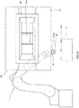
- Fig. 10 is a schematic view illustrating a field of view of the operator viewing through the transparent type display unit in a robot system of Modification 1 of Embodiment 2. Note that, in Fig. 10 , a state where the protrusion 21a contacts an inner circumferential surface of the cylindrical workpiece 20 held by the robot 1 is illustrated.
- the robot 1 of the robot system 100 of Modification 1 is the same in the fundamental configuration as the robot system 100 according to Embodiment 2, it is provided with a force sensor 3C provided to the sixth link 11f or the end effector 12 of the robot 1, as the sensor 3.
- the force sensor 3C is configured to detect a reaction force which acts on the end effector 12 from outside, or a force which acts externally by the end effector 12, and output components of the detected force (pressure information or force information) to the control device 4.
- the control device 4 displays the pressure information (force information) acquired from the force sensor 3C on the transparent type display unit 6, as the image screen 30.
- the control device 4 expresses force components in X-direction, Y-direction, and Z-direction detected by the force sensor 3C by first arrows indicated as thick lines, and displays the first arrows, and second arrows indicating X-direction, Y-direction, and Z-direction of the robot 1 on the transparent type display unit 6, as the image screen 30.
- the X-, Y-, and Z-directions indicate directions on the basis of the robot 1, where the X-direction indicates a left-and-right direction of the robot 1, the Y-direction indicates a front-and-rear direction of the robot 1, and the Z-direction indicates the up-and-down direction of the robot 1.
- control device 4 may control the transparent type display unit 6 so that the image screen 30 is displayed near the workpiece 20 or the end effector 12, or may control the transparent type display unit 6 so that the image screen 30 is displayed in a portion where the force components in the X-direction and the Y-direction occur (a portion where the workpiece 20 contacts the protrusion 21a).
- control device 4 may express torque components in the X-direction, the Y-direction, and the Z-direction detected by the force sensor 3C by arrows, and may display the arrows on the transparent type display unit 6, as the image screen 30.
- the control device 4 may control the transparent type display unit 6 to output the abnormality information to the image screen 30.
- the first threshold may be set suitably according to the type of the work to be performed by the robot 1, and may be a pressure value at which the workpiece 20 may be damaged, for example.
- Fig. 11 is a schematic view illustrating a field of view of the operator viewing through the transparent type display unit in a robot system of Modification 2 of Embodiment 2.
- the robot 1 of the robot system 100 of Modification 2 is the same in the fundamental configuration as the robot system 100 according to Embodiment 2, it includes an acceleration sensor 3D provided to the end effector 12 of the robot 1 as the sensor 3.
- the acceleration sensor 3D is configured to detect an acceleration of the end effector 12 (accurately, the workpiece 20 gripped by the end effector 12), and output the detected acceleration to the control device 4 as acceleration information.
- the control device 4 displays the acceleration information acquired from acceleration sensor 3D on the transparent type display unit 6, as the image screen 30.
- the control device 4 displays text information indicative of the acceleration information acquired from acceleration sensor 3D (acceleration ooG) on the transparent type display unit 6, as the image screen 30.
- the control device 4 may control the transparent type display unit 6 to output the abnormality information to the image screen 30.
- the first threshold it can be set suitably according to the type of the work to be performed by the robot 1, and may be an acceleration at which the workpiece 20 may be damaged, for example.
- Fig. 12 is a schematic view illustrating a field of view of the operator viewing through the transparent type display unit in a robot system of Modification 3 of Embodiment 2.
- the robot 1 of the robot system 100 of Modification 3 is the same in the fundamental configuration as the robot system 100 according to Embodiment 2, it includes a gyrosensor 3E provided to the end effector 12 of the robot 1 as the sensor 3.
- the gyrosensor 3E is configured to detect an angle (or an angular velocity) of the end effector 12 (accurately, the workpiece 20 gripped by the end effector 12), and output the detected angle (or the angular velocity) to the control device 4, as the inclination information.
- the control device 4 displays the inclination information acquired from the gyrosensor 3E on the transparent type display unit 6, as the image screen 30.
- the control device 4 expresses angle information of the workpiece 20 about the X-axis, and angle information of the workpiece 20 about the Y-axis by belt like arrows, and displays the belt like arrows and arrows indicating the X-axis and the Y-axis on the transparent type display unit 6, as the image screen 30.
- the X-axis and the Y-axis are axes in the same directions as the X-direction and the Y-direction of the robot 1, respectively.
- control device 4 may express the angle information acquired from the gyrosensor 3E as a rate to the entire rotation about each axis (360 degrees).
- a black portion indicates the rate of the rotation angle.
- the control device 4 may control the transparent type display unit 6 to output the abnormality information to the image screen 30.
- the first threshold can be set suitably according to the type of the work to be performed by the robot 1, and, for example, when the workpiece 20 is a container which accommodates liquid or powder, it may be an angle at which the liquid etc. may fall from the container.
- Fig. 13 is a schematic view illustrating a field of view of the operator viewing through the transparent type display unit in a robot system of Modification 4 of Embodiment 2. Note that, in Fig. 13 , a state where a work in which the workpiece 20 held by the robot 1 is placed at an equal interval (here, 15cm) on the pedestal 21 is performed is illustrated.
- the robot 1 of the robot system 100 of Modification 4 is the same in the fundamental configuration as the robot system 100 according to Embodiment 2, it includes a displacement sensor (position sensor) 3F provided to the end effector 12 of the robot 1, as the sensor 3.
- the displacement sensor 3F is configured to detect (measure) a distance between the workpiece 20 gripped by the end effector 12 and a workpiece 20A adjacent to the workpiece 20, and output the detected distance to the control device 4, as the positional information.
- the distance between the workpiece 20 gripped by the end effector 12 and the workpiece 20A adjacent to the workpiece 20 is 14.5cm.
- control device 4 displays the positional information acquired from the displacement sensor 3F on the transparent type display unit 6, as the image screen 30.
- the control device 4 displays characters of the positional information (here, 14.5cm) acquired from the displacement sensor 3F on the transparent type display unit 6, as the image screen 30.
- control device 4 may control the transparent type display unit 6 to output the abnormality information to the image screen 30, when the displacement sensor 3F detects the distance at a first threshold set beforehand or above.
- the first threshold can be set suitably according to the type of the work to be performed by the robot 1.
- the displacement sensor 3F is provided as the position sensor, it is not limited to this configuration.
- the rotation sensors which are disposed at the first to sixth joints JT1-JT6 of the robot 1 and detect the rotational positions of the drive motors (servo motors) may be used as the position sensors.
- the control device 4 may be configured to acquire the rotational positions of the drive motors detected by the rotation sensors, calculate position coordinates of the end effector 12 (workpiece 20) based on the rotational positions, and calculate the distance with the adjacent workpiece 20A based on the calculated position coordinates.
- a robot system according to Embodiment 3 is further provided with an output device, and the control device is configured to output to the output device, after the completion of the given first process, an inquiry on which operating mode the robot is to be operated among three operating modes comprised of an automatic operating mode, a manual operating mode, and a hybrid operating mode for the second process which is the next process of the first process, and when the manual operating mode or the hybrid operating mode is selected, display the first information which is information detected by the sensor on the transparent type display unit, as the image screen.
- the automatic operating mode refers to that the robot operates automatically according to a preset program.
- the manual operating mode refers to that the robot operates according to the operational instruction received from the user interface.
- the robot may be operated so as to completely follow the operational instruction received from the user interface, or the robot may be operated while correcting the operational instruction received from the user interface by using a preset program (for example, blurring correction).
- the hybrid operating mode refers to that the robot under automatic operation is corrected by a manual operation.
- Fig. 14 is a block diagram illustrating an outline configuration of a robot system according to Embodiment 3.
- the robot system 100 according to Embodiment 3 is the same in the fundamental configuration as the robot system 100 according to Embodiment 1, but it differs in that it is further provided with an output device 7. Moreover, the robot system 100 according to Embodiment 3 differs from the robot system 100 according to Embodiment 1 in that the control device 4 includes a corrector 43.
- the output device 7 is to output the information transmitted from the control device 4, and is configured to output the inquiry information on which operating mode the robot 1 is to be operated among the three operating modes comprised of the automatic operating mode, the manual operating mode, and the hybrid operating mode.
- the output device 7 may be, for example, a display unit such as a monitor, a speaker, and a printer.
- a display unit such as a monitor, a speaker, and a printer.
- the output device 7 displays (outputs) the information transmitted from the control device 4 as a projection of character(s), a picture, an image, and an animation or videos.
- the output device 7 is comprised of the speaker, it outputs the information transmitted from the control device 4 as audio information.
- the output device 7 is comprised of the printer, it prints out the information transmitted from the control device 4.
- the transparent type display unit 6 may also serve as the output device 7.
- the corrector 43 of the control device 4 instructs a correction of the operation of the robot 1 to the motion controller 41.
- the corrector 43 instructs to the motion controller 41, and instructs the motion controller 41 to correct the operation by the automatic operation of the robot 1 to operation according to the correction instruction signal from the user interface 2.
- the motion controller 41 controls the robot 1 so that the operation reflects the correction instruction from the user interface 2 according to the instruction from the corrector 43.
- the motion controller 41 of the control device 4 determines the operating mode of the process to be carried out by the robot 1 in a series of works by using this operational instruction as a trigger.
- the motion controller 41 can perform the determination of the operating mode of the process to be carried out by the robot 1 next, with reference to the operation sequence information 52 stored in the storage device 5.
- the motion controller 41 controls the robot 1 to operate in the determined operating mode.
- the motion controller 41 determines that the robot 1 is to be automatically operated, it reads the operation sequence information 52, and controls the robot 1 to carry out the operation defined by the program included in the operation sequence information 52.
- the motion controller 41 determines that the robot 1 is to be manually operated, it controls the robot 1 to operate based on the operational instruction received by the receiver 40 from the user interface 2.
- the motion controller 41 determines that the robot 1 is to be hybridly operated, it reads the operation sequence information 52, and carries out the operation defined by the program included in the operation sequence information 52. Then, when the receiver 40 receives the correction instruction signal as the input signal from the user interface 2 during the automatic operation of the robot 1, the motion controller 41 corrects the operation by the automatic operation of the robot 1 to the operation according to the correction instruction signal from the user interface 2. Then, when the output of the correction instruction signal from the user interface 2 and the receiver 40 stops the reception of the correction instruction signal, or when the receiver 40 receives a signal for instructing a resumption of the automatic operation of the robot 1 from the user interface 2, the motion controller 41 resumes the automatic operation of the robot 1.
- the motion controller 41 may transmit information indicating the termination of the automatic operating mode to the output controller 42, after the automatic operating mode of the robot 1 is completed.
- the output controller 42 outputting the information indicating the termination of the automatic operating mode to the output device 7 for the operator, the operator can understand that the automatic operating mode is terminated.
- the motion controller 41 outputs the inquiry information on which operating mode the robot 1 is to be operated among the three operating modes comprised of the automatic operating mode, the manual operating mode, and the hybrid operating mode, to the output controller 42.
- the output controller 42 may control the output device 7 to output the information.
- the output controller 42 may control the output device 7 to output the information.
- the output controller 42 controls the output device 7 to output the information.
- the operator can select the operating mode in which the robot 1 is to be operated from the three operating modes, and by operating the user interface 2, the selection information can be outputted to the receiver 40 of the control device 4.
- the user interface 2 is configured to output the operating mode selected by the operator from the three operating modes, as the selection information.
- the user interface 2 may be configured to output information indicating a termination of the operating mode.
- the user interface 2 may be separately provided with an input part where a start instruction of a work, a notice of completion of the work by the manual operation, etc. are inputted.
- Fig. 15 is a flowchart illustrating one example of operation of the robot system according to Embodiment 3.
- the control device 4 determines whether the first process which is at least one of the plurality of processes is ended (Step S301). In detail, the motion controller 41 of the control device 4 determines whether the automatic operation is ended, or whether information indicating a termination of the manual operation is received from the user interface 2 or information indicating a termination of the hybrid operation is received, through the receiver 40.
- the motion controller 41 of the control device 4 determines that the automatic operation has not ended, or the information indicating the termination of the manual operation has not received from the user interface 2 or the information indicating the termination of the hybrid operation has not received, through the receiver 40 (No at Step S301), it ends this program. Note that, when the control device 4 ends this program, it executes this program again, for example, after 50msec.
- the motion controller 41 of the control device 4 determines that the automatic operation is ended, or the information indicating the termination of the manual operation is received from the user interface 2 or the information indicating the termination of the hybrid operation is received, through the receiver 40 (Yes at Step S301), it performs processing at Step S302.
- the control device 4 displays (outputs) on/to the output device 7 the inquiry information on which operating mode the robot 1 is to be operated among the three operating modes comprised of the automatic operating mode, the manual operating mode, and the hybrid operating mode.
- the motion controller 41 of the control device 4 outputs the inquiry information to the output device 7 through the output controller 42. Then, by the output device 7 acquiring the inquiry information, the inquiry information on which operating mode the robot 1 is to be operated among the three operating modes is displayed to the operator.
- the operator selects one of the three operating modes, and operates the user interface 2 to output the selected operating mode as the selection information.
- the motion controller 41 of the control device 4 determines whether the selection information is inputted into the receiver 40 from the user interface 2 (Step S303). If the motion controller 41 determines that the selection information is not inputted into the receiver 40 from the user interface 2 (No at Step S303), it returns to Step S302 and repeats Step S302 and Step S303 until the selection information is inputted into the receiver 40 from the user interface 2. On the other hand, if the motion controller 41 determines that the selection information is inputted into the receiver 40 from the user interface 2 (Yes at Step S303), it transits to Step S304.
- the motion controller 41 of the control device 4 determines whether the selection information inputted through the receiver 40 from the user interface 2 is the manual operating mode or the hybrid operating mode.
- the motion controller 41 of the control device 4 determines that the selection information acquired at Step S303 is the automatic operating mode (No at Step S304), it ends this program. On the other hand, if the motion controller 41 of the control device 4 determines that the selection information acquired at Step S303 is the manual operating mode or the hybrid operating mode (Yes at Step S304), it outputs the first information detected by the sensor 3 to the transparent type display unit 6, as the image screen (Step S305). In detail, the control device 4 displays the image imaged by the camera 3A on the transparent type display unit 6.
- control device 4 ends this program. Note that, when the control device 4 ends this program, it executes this program again, for example, after 50msec.
- the control device 4 displays the first information detected by the sensor 3 on the transparent type display unit 6, as the image screen.
- the operator operates the user interface 2 to operate the robot 1.
- the first information detected by the sensor 3 is required, the first information can be displayed on the transparent type display unit 6, as the image screen.
- the senor 3 is comprised of the camera 3A, it is not limited to this configuration.
- the sensor 3 may be comprised of various kinds of sensors, such as a vibration sensor.
- a robot system according to Embodiment 4 is configured so that the sensor is comprised of a camera, and when the robot is operated by the user interface, the control device displays the image information imaged by the camera on the transparent type display unit, as the image screen.
- control device may be configured to display the image screen on the transparent type display unit, while changing the size of the image screen according to an operating speed of the robot.
- the image information imaged by the camera may be displayed on the transparent type display unit so that the size of the image screen is increased as the operating speed of the robot becomes slower.
- Figs. 16 to 18 are the schematic views illustrating a field of view of the operator viewing through the transparent type display unit in the robot system according to Embodiment 4. Note that, in Figs. 16 to 18 , the operating speed of the robot 1 is smaller in this order of the figures.
- the control device 4 controls the transparent type display unit 6 to change the size of the image screen 30 which projects the image information imaged by the camera 3A displayed on the transparent type display unit 6 according to the operating speed of the robot 1.
- the control device 4 controls the transparent type display unit 6 to increase the size of the image screen 30 which projects the image information imaged by the camera 3A as the operating speed of the robot 1 becomes slower.
- control device 4 may control the transparent type display unit 6 so that the size of the image screen 30 is smoothly increased in inverse proportion to the operating speed of the robot 1. Moreover, the control device 4 may control the transparent type display unit 6 so that a relation between the operating speed of the robot 1 and the size of the image screen 30 becomes a function expressed by a high order function such as a quadratic function or a cubic function, an exponential function, or a logarithmic function. Further, the control device 4 may control the transparent type display unit 6 so that the size of the image screen 30 is increased in a stepped manner according to the operating speed of the robot 1.
- the operating speed of the robot 1 is decreased in order for the operator to carefully operate the robot 1. At this time, the operator carefully views the image information near the tip-end part of the robot 1.
- control device 4 controls the transparent type display unit 6 to increase the size of the image screen 30 as the operating speed of the robot 1 becomes slower.
- the image screen 30 becomes easier to be viewed, the operator's burden can be further reduced, and the work efficiency can be further improved.
- a robot system according to Embodiment 5 is configured so that the sensor is comprised of a camera, and the control device displays the image screen on the transparent type display unit, while changing the transparency of the image screen according to the operating speed of the robot.
- control device is configured to display the image information imaged by the camera on the transparent type display unit, while reducing the transparency of the image screen as the operating speed of the robot becomes slower.
- Figs. 19 to 21 are schematic views illustrating a field of view of the operator viewing through the transparent type display unit in the robot system according to Embodiment 5. Note that, in Figs. 19 to 21 , the operating speed of the robot 1 is smaller in this order of the figures.
- the control device 4 controls the transparent type display unit 6 to change the transparency of the image screen 30 which projects the image information imaged by the camera 3A displayed on the transparent type display unit 6 according to the operating speed of the robot 1.
- the control device 4 controls the transparent type display unit 6 to reduce the transparency of the image screen 30 which projects the image information imaged by the camera 3A displayed on the transparent type display unit 6 as the operating speed of the robot 1 becomes slower.
- control device 4 may control the transparent type display unit 6 so that the transparency of the image screen 30 is smoothly reduced in proportion to the operating speed of the robot 1. Moreover, the control device 4 may control the transparent type display unit 6 so that a relation between the operating speed of the robot 1 and the size of the image screen 30 becomes a function expressed by a high order function such as a quadratic function or a cubic function, an exponential function, or a logarithmic function. Further, the control device 4 may control the transparent type display unit 6 so that the transparency of the image screen 30 is reduced in a stepped manner according to the operating speed of the robot 1.
- the operator when causing the robot 1 to perform the operation which requires the positioning of the tip-end part of the robot 1 (end effector 12), the operator carefully views the image information near the tip-end part of the robot 1. At this time, for example, if the image screen 30 and the robot 1 are displayed in an overlapped manner on the display part 6a of the transparent type display unit 6, it may be difficult for the operator to see the image screen 30.
- the control device 4 controls the transparent type display unit 6 to reduce the transparency of the image screen 30 as the operating speed of the robot 1 becomes slower. Therefore, for the operator, for example, the robot 1 which is located as a background of the image screen 30 disappears, and thereby, the image screen 30 can be easier to be viewed. Thus, the operator's burden can be further reduced and the work efficiency can be further improved.
- a robot system according to Embodiment 6 is configured so that the sensor is comprised of a camera, and the control device changes the color of the image screen imaged by the camera which is displayed on the transparent type display unit according to the operating speed of the robot.
- control device may be configured, when the operating speed of the robot is the given first speed set beforehand or below, to display the image information imaged by the camera in the image screen as a monochrome image on the transparent type display unit, and when the operating speed of the robot is above the first speed, to display the image screen imaged by the camera in the image screen as a color image.
- Fig. 22 is a flowchart illustrating one example of operation of the robot system according to Embodiment 6.
- the operation of the robot system 100 according to Embodiment 6 is fundamentally the same as the operation of the robot system 100 according to Embodiment 1, but the operations at and after Step S102 differ.
- the operations at and after the determination by the control device 4 whether the robot 1 is to be operated at the first speed or below differ.
- control device 4 determines that the robot 1 is to be operated at the first speed or below (Yes at Step S102), it outputs the image information inputted from the camera 3A to the transparent type display unit 6 as the color image (step S103A), and ends this program. Note that, when the control device 4 ends this program, it executes this program again, for example, after 50msec.
- control device 4 determines that the robot 1 is to be operated above the first speed (No at Step S102), it outputs the image information inputted from the camera 3A to the transparent type display unit 6 as the monochrome image (Step S104), and ends this program. Note that, when the control device 4 ends this program, it executes this program again, for example, after 50msec.
- the control device 4 displays the image screen 30 on the transparent type display unit 6 as the color image. Therefore, the image screen 30 can be easier to be viewed for the operator. Thus, the operator's burden can be further reduced and the work efficiency can be further improved.
- the robot system according to Embodiment 7 is configured so that a memory which stores a first operating area which is an area where the robot is operable in a given process is further provided, and when the robot is operated by the user interface, the control device displays the first operating area on the transparent type display unit.
- Fig. 23 is a schematic view illustrating a field of view of the operator viewing through the transparent type display unit in the robot system according to Embodiment 7.
- the control device 4 displays a first operating area 31 stored beforehand in the storage device 5 on the transparent type display unit 6.
- the first operating area 31 is an area where the robot 1 is operable in the given process, and is an area used as an index when a worker operates the robot 1 to cause the robot 1 to perform the given process.
- the first operating area 31 can be suitably set beforehand by an experiment etc., and is suitably set according to the type of the work to be performed by the robot 1.
- the first operating area 31 may be a range (area) where, for example, the robot 1 is operable and is defined according to the size of the robot 1, a movable range of each joint, etc. Moreover, the first operating area 31 may be a range (area) where the workpiece 20 gripped by the robot 1 is movable. Further, the first operating area 31 may be a range (area) of -10 to +10cm from the path of the workpiece 20 when the robot 1 optimally performs the work (when the robot 1 is able to finish the work the fastest).
- the control device 4 displays a range where the workpiece 20 can be located in order to fit the workpiece 20 held by the robot 1 onto the protrusion 21a (a range where the workpiece 20 is movable; a hatched portion) on the transparent type display unit 6, as the first operating area 31. That is, in Embodiment 7, the control device 4 displays the first operating area 31 on the transparent type display unit 6, as augmented reality.
- the operator can easily operate the robot 1 and can improve the work efficiency.
- the first operating area 31 may be stored in the storage device 5 so that its area in changed according to the operating speed of the robot 1.
- the first operating area 31 may be stored in the storage device 5 so that its area is reduced as the operating speed of the robot 1 becomes slower.
- Fig. 24 is a schematic view illustrating a field of view of the operator viewing through the transparent type display unit in the robot system of Modification 1 of Embodiment 7.
- the control device 4 controls the transparent type display unit 6 to display the first operating area 31 on the image screen 30 which projects the image information imaged by the camera 3A.
- control device 4 may display the first operating area 31 on the image screen 30, and may display the first operating area 31 as augmented reality, similar to Embodiment 7 described above.
Landscapes
- Engineering & Computer Science (AREA)
- Robotics (AREA)
- Mechanical Engineering (AREA)
- General Engineering & Computer Science (AREA)
- Theoretical Computer Science (AREA)
- Physics & Mathematics (AREA)
- General Physics & Mathematics (AREA)
- Human Computer Interaction (AREA)
- Manufacturing & Machinery (AREA)
- Quality & Reliability (AREA)
- Automation & Control Theory (AREA)
- Multimedia (AREA)
- Manipulator (AREA)
Applications Claiming Priority (2)
| Application Number | Priority Date | Filing Date | Title |
|---|---|---|---|
| JP2017078190A JP6850183B2 (ja) | 2017-04-11 | 2017-04-11 | ロボットシステム及びその運転方法 |
| PCT/JP2018/015132 WO2018190345A1 (fr) | 2017-04-11 | 2018-04-10 | Système de robot et procédé d'actionnement d'un tel système de robot |
Publications (2)
| Publication Number | Publication Date |
|---|---|
| EP3610996A1 true EP3610996A1 (fr) | 2020-02-19 |
| EP3610996A4 EP3610996A4 (fr) | 2021-01-13 |
Family
ID=63793421
Family Applications (1)
| Application Number | Title | Priority Date | Filing Date |
|---|---|---|---|
| EP18784839.5A Pending EP3610996A4 (fr) | 2017-04-11 | 2018-04-10 | Système de robot et procédé d'actionnement d'un tel système de robot |
Country Status (5)
| Country | Link |
|---|---|
| US (1) | US11358286B2 (fr) |
| EP (1) | EP3610996A4 (fr) |
| JP (1) | JP6850183B2 (fr) |
| CN (1) | CN110505947B (fr) |
| WO (1) | WO2018190345A1 (fr) |
Cited By (1)
| Publication number | Priority date | Publication date | Assignee | Title |
|---|---|---|---|---|
| US11534912B2 (en) | 2019-04-26 | 2022-12-27 | Fanuc Corporation | Vibration display device, operation program creating device, and system |
Families Citing this family (5)
| Publication number | Priority date | Publication date | Assignee | Title |
|---|---|---|---|---|
| JP7000364B2 (ja) | 2019-01-29 | 2022-01-19 | ファナック株式会社 | ロボットシステム |
| KR20220017893A (ko) * | 2019-04-06 | 2022-02-14 | 일렉트릭 쉽 로보틱스, 아이앤씨. | 원격작동로봇을 위한 시스템, 장치 및 방법 |
| CN111203884B (zh) * | 2020-01-19 | 2021-10-15 | 吉利汽车研究院(宁波)有限公司 | 机器人控制方法及装置 |
| CN112873214B (zh) * | 2021-03-18 | 2024-02-23 | 中国工程物理研究院机械制造工艺研究所 | 一种基于加速度信息的机器人状态实时监控系统及方法 |
| US11898996B2 (en) * | 2022-01-03 | 2024-02-13 | Teng-Jen Yang | Test system with detection feedback |
Family Cites Families (20)
| Publication number | Priority date | Publication date | Assignee | Title |
|---|---|---|---|---|
| JPH09200650A (ja) * | 1996-01-17 | 1997-07-31 | Nippon Steel Corp | 映像表示方法及びその装置 |
| SE0203908D0 (sv) | 2002-12-30 | 2002-12-30 | Abb Research Ltd | An augmented reality system and method |
| CN2728726Y (zh) * | 2004-04-02 | 2005-09-28 | 李朝辉 | 生物信息随动即时示教控制机器人 |
| US7843431B2 (en) * | 2007-04-24 | 2010-11-30 | Irobot Corporation | Control system for a remote vehicle |
| JP5665333B2 (ja) * | 2010-03-10 | 2015-02-04 | キヤノン株式会社 | 情報処理装置および情報処理装置の制御方法 |
| JP2012218120A (ja) * | 2011-04-12 | 2012-11-12 | Seiko Epson Corp | マニピュレーター動作予告装置、ロボットシステム及びマニピュレーター動作予告方法 |
| US9037297B2 (en) * | 2011-09-15 | 2015-05-19 | Persimmon Technologies Corporation | System and method for operation of a robot |
| JP2013091114A (ja) * | 2011-10-05 | 2013-05-16 | Kyokko Denki Kk | インタラクション操作システム |
| WO2013150599A1 (fr) * | 2012-04-02 | 2013-10-10 | 株式会社安川電機 | Système robotisé et aire de travail |
| JP5945968B2 (ja) * | 2013-09-03 | 2016-07-05 | 株式会社安川電機 | ロボットハンド、ロボットシステム、及び物品のデパレタイズ方法 |
| WO2015145725A1 (fr) * | 2014-03-28 | 2015-10-01 | 三菱重工マシナリーテクノロジー株式会社 | Dispositif de présentation d'informations, système de grue et procédé de présentation d'informations |
| JP6350011B2 (ja) * | 2014-06-20 | 2018-07-04 | オムロン株式会社 | ロボット制御システム |
| JP2016107379A (ja) * | 2014-12-08 | 2016-06-20 | ファナック株式会社 | 拡張現実対応ディスプレイを備えたロボットシステム |
| US9643314B2 (en) * | 2015-03-04 | 2017-05-09 | The Johns Hopkins University | Robot control, training and collaboration in an immersive virtual reality environment |
| KR101776576B1 (ko) * | 2015-09-25 | 2017-09-08 | 숭실대학교산학협력단 | 로봇 제어 시스템 및 방법 |
| CN108472095B (zh) * | 2015-12-29 | 2021-11-02 | 皇家飞利浦有限公司 | 用于机器人外科手术的使用虚拟现实设备的系统、控制器和方法 |
| US10956739B2 (en) * | 2016-06-27 | 2021-03-23 | Autodesk, Inc. | Augmented reality robotic system visualization |
| CN106393121A (zh) * | 2016-10-31 | 2017-02-15 | 江苏华航威泰机器人科技有限公司 | 一种移动机器人控制系统 |
| US10684480B2 (en) * | 2017-03-16 | 2020-06-16 | Denso Wave Incorporated | Information display system |
| JP7187820B2 (ja) * | 2018-05-29 | 2022-12-13 | セイコーエプソン株式会社 | 制御装置、ヘッドマウントディスプレイ、及びロボットシステム |
-
2017
- 2017-04-11 JP JP2017078190A patent/JP6850183B2/ja active Active
-
2018
- 2018-04-10 CN CN201880024568.3A patent/CN110505947B/zh active Active
- 2018-04-10 WO PCT/JP2018/015132 patent/WO2018190345A1/fr unknown
- 2018-04-10 US US16/604,719 patent/US11358286B2/en active Active
- 2018-04-10 EP EP18784839.5A patent/EP3610996A4/fr active Pending
Cited By (2)
| Publication number | Priority date | Publication date | Assignee | Title |
|---|---|---|---|---|
| US11534912B2 (en) | 2019-04-26 | 2022-12-27 | Fanuc Corporation | Vibration display device, operation program creating device, and system |
| DE102020110252B4 (de) | 2019-04-26 | 2023-11-02 | Fanuc Corporation | Vibrationsanzeigeeinrichtung, Betriebsprogrammerstellungseinrichtung und System |
Also Published As
| Publication number | Publication date |
|---|---|
| CN110505947A (zh) | 2019-11-26 |
| WO2018190345A1 (fr) | 2018-10-18 |
| JP2018176342A (ja) | 2018-11-15 |
| CN110505947B (zh) | 2022-10-11 |
| EP3610996A4 (fr) | 2021-01-13 |
| US11358286B2 (en) | 2022-06-14 |
| US20200055194A1 (en) | 2020-02-20 |
| JP6850183B2 (ja) | 2021-03-31 |
Similar Documents
| Publication | Publication Date | Title |
|---|---|---|
| EP3610996A1 (fr) | Système de robot et procédé d'actionnement d'un tel système de robot | |
| EP3342560B1 (fr) | Système de robot et son procédé de fonctionnement | |
| CN111093903B (zh) | 机器人系统及其运行方法 | |
| US20170165841A1 (en) | Robot system equipped with video display apparatus that displays image of virtual object in superimposed fashion on real image of robot | |
| US11865697B2 (en) | Robot system and method for operating same | |
| JP6589604B2 (ja) | ティーチング結果表示システム | |
| US20200361092A1 (en) | Robot operating device, robot, and robot operating method | |
| JP2020019127A (ja) | 協調動作支援装置 | |
| JP2001121458A (ja) | ロボットコントローラ | |
| WO2022009765A1 (fr) | Dispositif de commande de robot | |
| CN114761180B (zh) | 机器人系统 | |
| JP6435940B2 (ja) | ロボット操作装置、及びロボット操作プログラム | |
| US20220184814A1 (en) | Robot system | |
| JP2020037165A (ja) | 動作プログラムの変数を監視するロボットの制御装置 | |
| US20220214685A1 (en) | Remote operating device | |
| JP2024006557A (ja) | 表示システムおよび教示システム |
Legal Events
| Date | Code | Title | Description |
|---|---|---|---|
| STAA | Information on the status of an ep patent application or granted ep patent |
Free format text: STATUS: THE INTERNATIONAL PUBLICATION HAS BEEN MADE |
|
| PUAI | Public reference made under article 153(3) epc to a published international application that has entered the european phase |
Free format text: ORIGINAL CODE: 0009012 |
|
| STAA | Information on the status of an ep patent application or granted ep patent |
Free format text: STATUS: REQUEST FOR EXAMINATION WAS MADE |
|
| 17P | Request for examination filed |
Effective date: 20191108 |
|
| AK | Designated contracting states |
Kind code of ref document: A1 Designated state(s): AL AT BE BG CH CY CZ DE DK EE ES FI FR GB GR HR HU IE IS IT LI LT LU LV MC MK MT NL NO PL PT RO RS SE SI SK SM TR |
|
| AX | Request for extension of the european patent |
Extension state: BA ME |
|
| DAV | Request for validation of the european patent (deleted) | ||
| DAX | Request for extension of the european patent (deleted) | ||
| A4 | Supplementary search report drawn up and despatched |
Effective date: 20201215 |
|
| RIC1 | Information provided on ipc code assigned before grant |
Ipc: B25J 13/00 20060101ALI20201209BHEP Ipc: B25J 19/04 20060101AFI20201209BHEP Ipc: B25J 13/06 20060101ALI20201209BHEP Ipc: G02B 27/01 20060101ALI20201209BHEP Ipc: B25J 19/02 20060101ALI20201209BHEP Ipc: G06F 3/01 20060101ALI20201209BHEP |
|
| STAA | Information on the status of an ep patent application or granted ep patent |
Free format text: STATUS: EXAMINATION IS IN PROGRESS |
|
| 17Q | First examination report despatched |
Effective date: 20240314 |