EP3610917A1 - Cardiac modulation facilitation methods and systems - Google Patents
Cardiac modulation facilitation methods and systems Download PDFInfo
- Publication number
- EP3610917A1 EP3610917A1 EP19179265.4A EP19179265A EP3610917A1 EP 3610917 A1 EP3610917 A1 EP 3610917A1 EP 19179265 A EP19179265 A EP 19179265A EP 3610917 A1 EP3610917 A1 EP 3610917A1
- Authority
- EP
- European Patent Office
- Prior art keywords
- parameter
- electrical
- electrical signals
- series
- heart
- Prior art date
- Legal status (The legal status is an assumption and is not a legal conclusion. Google has not performed a legal analysis and makes no representation as to the accuracy of the status listed.)
- Pending
Links
- 238000000034 method Methods 0.000 title abstract description 150
- 230000000747 cardiac effect Effects 0.000 title description 30
- 210000001147 pulmonary artery Anatomy 0.000 claims abstract description 214
- 230000000694 effects Effects 0.000 claims abstract description 126
- 230000004007 neuromodulation Effects 0.000 claims abstract description 109
- 230000004044 response Effects 0.000 claims abstract description 80
- 230000000638 stimulation Effects 0.000 claims abstract description 75
- 230000001225 therapeutic effect Effects 0.000 claims abstract description 59
- 210000005166 vasculature Anatomy 0.000 claims abstract description 41
- 239000008280 blood Substances 0.000 claims description 28
- 210000004369 blood Anatomy 0.000 claims description 28
- 230000001133 acceleration Effects 0.000 claims description 21
- 238000007493 shaping process Methods 0.000 description 46
- 230000002685 pulmonary effect Effects 0.000 description 41
- 210000005241 right ventricle Anatomy 0.000 description 28
- 210000005245 right atrium Anatomy 0.000 description 21
- 210000005036 nerve Anatomy 0.000 description 18
- 238000004458 analytical method Methods 0.000 description 15
- 230000002612 cardiopulmonary effect Effects 0.000 description 14
- 210000003748 coronary sinus Anatomy 0.000 description 14
- 210000002620 vena cava superior Anatomy 0.000 description 14
- 230000002093 peripheral effect Effects 0.000 description 12
- QVGXLLKOCUKJST-UHFFFAOYSA-N atomic oxygen Chemical compound [O] QVGXLLKOCUKJST-UHFFFAOYSA-N 0.000 description 10
- 229910052760 oxygen Inorganic materials 0.000 description 10
- 239000001301 oxygen Substances 0.000 description 10
- 210000001631 vena cava inferior Anatomy 0.000 description 10
- 230000009471 action Effects 0.000 description 9
- 230000002567 autonomic effect Effects 0.000 description 9
- 210000003403 autonomic nervous system Anatomy 0.000 description 9
- 230000008569 process Effects 0.000 description 9
- 206010007556 Cardiac failure acute Diseases 0.000 description 8
- 238000004891 communication Methods 0.000 description 8
- 230000008901 benefit Effects 0.000 description 7
- 238000004422 calculation algorithm Methods 0.000 description 7
- 239000002671 adjuvant Substances 0.000 description 6
- 210000001367 artery Anatomy 0.000 description 6
- 229940030602 cardiac therapy drug Drugs 0.000 description 6
- 230000006835 compression Effects 0.000 description 6
- 238000007906 compression Methods 0.000 description 6
- 230000002526 effect on cardiovascular system Effects 0.000 description 6
- 210000005240 left ventricle Anatomy 0.000 description 6
- 239000004020 conductor Substances 0.000 description 5
- 210000000709 aorta Anatomy 0.000 description 4
- 230000017531 blood circulation Effects 0.000 description 4
- 230000008859 change Effects 0.000 description 4
- 210000005246 left atrium Anatomy 0.000 description 4
- 238000012986 modification Methods 0.000 description 4
- 230000004048 modification Effects 0.000 description 4
- 210000004165 myocardium Anatomy 0.000 description 4
- 229920002635 polyurethane Polymers 0.000 description 4
- 239000004814 polyurethane Substances 0.000 description 4
- 208000020446 Cardiac disease Diseases 0.000 description 3
- WQZGKKKJIJFFOK-GASJEMHNSA-N Glucose Natural products OC[C@H]1OC(O)[C@H](O)[C@@H](O)[C@@H]1O WQZGKKKJIJFFOK-GASJEMHNSA-N 0.000 description 3
- 206010019280 Heart failures Diseases 0.000 description 3
- 208000037265 diseases, disorders, signs and symptoms Diseases 0.000 description 3
- 239000012530 fluid Substances 0.000 description 3
- 230000006870 function Effects 0.000 description 3
- 239000008103 glucose Substances 0.000 description 3
- 208000019622 heart disease Diseases 0.000 description 3
- 230000000004 hemodynamic effect Effects 0.000 description 3
- 230000000297 inotrophic effect Effects 0.000 description 3
- 238000003780 insertion Methods 0.000 description 3
- 230000037431 insertion Effects 0.000 description 3
- 239000000463 material Substances 0.000 description 3
- 229910052751 metal Inorganic materials 0.000 description 3
- 239000002184 metal Substances 0.000 description 3
- 229910001092 metal group alloy Inorganic materials 0.000 description 3
- 230000036961 partial effect Effects 0.000 description 3
- 210000001519 tissue Anatomy 0.000 description 3
- 230000002861 ventricular Effects 0.000 description 3
- 208000035478 Interatrial communication Diseases 0.000 description 2
- PXHVJJICTQNCMI-UHFFFAOYSA-N Nickel Chemical compound [Ni] PXHVJJICTQNCMI-UHFFFAOYSA-N 0.000 description 2
- 208000008883 Patent Foramen Ovale Diseases 0.000 description 2
- 230000001154 acute effect Effects 0.000 description 2
- 208000013914 atrial heart septal defect Diseases 0.000 description 2
- 206010003664 atrial septal defect Diseases 0.000 description 2
- 230000002051 biphasic effect Effects 0.000 description 2
- 230000001684 chronic effect Effects 0.000 description 2
- 208000035475 disorder Diseases 0.000 description 2
- VYFYYTLLBUKUHU-UHFFFAOYSA-N dopamine Chemical compound NCCC1=CC=C(O)C(O)=C1 VYFYYTLLBUKUHU-UHFFFAOYSA-N 0.000 description 2
- 238000003384 imaging method Methods 0.000 description 2
- 239000004041 inotropic agent Substances 0.000 description 2
- 238000009434 installation Methods 0.000 description 2
- 230000000670 limiting effect Effects 0.000 description 2
- 238000005259 measurement Methods 0.000 description 2
- 150000002739 metals Chemical class 0.000 description 2
- 230000002107 myocardial effect Effects 0.000 description 2
- HLXZNVUGXRDIFK-UHFFFAOYSA-N nickel titanium Chemical compound [Ti].[Ti].[Ti].[Ti].[Ti].[Ti].[Ti].[Ti].[Ti].[Ti].[Ti].[Ni].[Ni].[Ni].[Ni].[Ni].[Ni].[Ni].[Ni].[Ni].[Ni].[Ni].[Ni].[Ni].[Ni] HLXZNVUGXRDIFK-UHFFFAOYSA-N 0.000 description 2
- 229910001000 nickel titanium Inorganic materials 0.000 description 2
- 230000003287 optical effect Effects 0.000 description 2
- 230000036284 oxygen consumption Effects 0.000 description 2
- -1 polyethylene Polymers 0.000 description 2
- 238000012545 processing Methods 0.000 description 2
- 230000002829 reductive effect Effects 0.000 description 2
- 239000012781 shape memory material Substances 0.000 description 2
- 239000010935 stainless steel Substances 0.000 description 2
- 229910001220 stainless steel Inorganic materials 0.000 description 2
- 230000009885 systemic effect Effects 0.000 description 2
- 238000002560 therapeutic procedure Methods 0.000 description 2
- 230000007704 transition Effects 0.000 description 2
- 238000011282 treatment Methods 0.000 description 2
- 230000002792 vascular Effects 0.000 description 2
- 206010002329 Aneurysm Diseases 0.000 description 1
- 206010002383 Angina Pectoris Diseases 0.000 description 1
- 206010003840 Autonomic nervous system imbalance Diseases 0.000 description 1
- 208000031229 Cardiomyopathies Diseases 0.000 description 1
- 206010050202 Carotid sinus syndrome Diseases 0.000 description 1
- 206010011224 Cough Diseases 0.000 description 1
- JRWZLRBJNMZMFE-UHFFFAOYSA-N Dobutamine Chemical compound C=1C=C(O)C(O)=CC=1CCNC(C)CCC1=CC=C(O)C=C1 JRWZLRBJNMZMFE-UHFFFAOYSA-N 0.000 description 1
- 206010020772 Hypertension Diseases 0.000 description 1
- 206010021137 Hypovolaemia Diseases 0.000 description 1
- 206010061216 Infarction Diseases 0.000 description 1
- 208000001089 Multiple system atrophy Diseases 0.000 description 1
- 241000699666 Mus <mouse, genus> Species 0.000 description 1
- 241000699670 Mus sp. Species 0.000 description 1
- 229910000990 Ni alloy Inorganic materials 0.000 description 1
- 206010031123 Orthopnoea Diseases 0.000 description 1
- 206010031127 Orthostatic hypotension Diseases 0.000 description 1
- 208000002193 Pain Diseases 0.000 description 1
- 208000005228 Pericardial Effusion Diseases 0.000 description 1
- 239000004952 Polyamide Substances 0.000 description 1
- 239000004698 Polyethylene Substances 0.000 description 1
- 239000004642 Polyimide Substances 0.000 description 1
- 239000004721 Polyphenylene oxide Substances 0.000 description 1
- FAPWRFPIFSIZLT-UHFFFAOYSA-M Sodium chloride Chemical compound [Na+].[Cl-] FAPWRFPIFSIZLT-UHFFFAOYSA-M 0.000 description 1
- 229910001069 Ti alloy Inorganic materials 0.000 description 1
- 230000005856 abnormality Effects 0.000 description 1
- 230000002730 additional effect Effects 0.000 description 1
- 238000009098 adjuvant therapy Methods 0.000 description 1
- VREFGVBLTWBCJP-UHFFFAOYSA-N alprazolam Chemical compound C12=CC(Cl)=CC=C2N2C(C)=NN=C2CN=C1C1=CC=CC=C1 VREFGVBLTWBCJP-UHFFFAOYSA-N 0.000 description 1
- 238000003491 array Methods 0.000 description 1
- 206010003119 arrhythmia Diseases 0.000 description 1
- 230000015572 biosynthetic process Effects 0.000 description 1
- 230000036772 blood pressure Effects 0.000 description 1
- 210000000748 cardiovascular system Anatomy 0.000 description 1
- 239000003795 chemical substances by application Substances 0.000 description 1
- IUWCPXJTIPQGTE-UHFFFAOYSA-N chromium cobalt Chemical compound [Cr].[Co].[Co].[Co] IUWCPXJTIPQGTE-UHFFFAOYSA-N 0.000 description 1
- 230000002057 chronotropic effect Effects 0.000 description 1
- 230000000295 complement effect Effects 0.000 description 1
- 229920006147 copolyamide elastomer Polymers 0.000 description 1
- 230000008878 coupling Effects 0.000 description 1
- 238000010168 coupling process Methods 0.000 description 1
- 238000005859 coupling reaction Methods 0.000 description 1
- 238000013461 design Methods 0.000 description 1
- 238000001514 detection method Methods 0.000 description 1
- 230000006866 deterioration Effects 0.000 description 1
- 238000003745 diagnosis Methods 0.000 description 1
- 238000010586 diagram Methods 0.000 description 1
- 201000010099 disease Diseases 0.000 description 1
- 238000006073 displacement reaction Methods 0.000 description 1
- 229960001089 dobutamine Drugs 0.000 description 1
- 229960003638 dopamine Drugs 0.000 description 1
- 208000019479 dysautonomia Diseases 0.000 description 1
- 239000012777 electrically insulating material Substances 0.000 description 1
- 238000002565 electrocardiography Methods 0.000 description 1
- 239000000835 fiber Substances 0.000 description 1
- 238000007667 floating Methods 0.000 description 1
- 238000002594 fluoroscopy Methods 0.000 description 1
- 230000014509 gene expression Effects 0.000 description 1
- 230000004217 heart function Effects 0.000 description 1
- 208000025339 heart septal defect Diseases 0.000 description 1
- 229920001903 high density polyethylene Polymers 0.000 description 1
- 239000004700 high-density polyethylene Substances 0.000 description 1
- 239000007943 implant Substances 0.000 description 1
- 238000010348 incorporation Methods 0.000 description 1
- 230000002401 inhibitory effect Effects 0.000 description 1
- 239000011810 insulating material Substances 0.000 description 1
- 230000003993 interaction Effects 0.000 description 1
- 208000028867 ischemia Diseases 0.000 description 1
- 210000004072 lung Anatomy 0.000 description 1
- 239000011159 matrix material Substances 0.000 description 1
- 210000004126 nerve fiber Anatomy 0.000 description 1
- 230000001272 neurogenic effect Effects 0.000 description 1
- 238000005457 optimization Methods 0.000 description 1
- 208000012144 orthopnea Diseases 0.000 description 1
- 229920002647 polyamide Polymers 0.000 description 1
- 239000004417 polycarbonate Substances 0.000 description 1
- 229920000515 polycarbonate Polymers 0.000 description 1
- 229920000728 polyester Polymers 0.000 description 1
- 229920000570 polyether Polymers 0.000 description 1
- 229920000573 polyethylene Polymers 0.000 description 1
- 229920001721 polyimide Polymers 0.000 description 1
- 229920000642 polymer Polymers 0.000 description 1
- 229920000098 polyolefin Polymers 0.000 description 1
- 230000001376 precipitating effect Effects 0.000 description 1
- 230000002265 prevention Effects 0.000 description 1
- 208000018290 primary dysautonomia Diseases 0.000 description 1
- 238000004886 process control Methods 0.000 description 1
- 208000002815 pulmonary hypertension Diseases 0.000 description 1
- 210000003492 pulmonary vein Anatomy 0.000 description 1
- 238000005086 pumping Methods 0.000 description 1
- 230000008707 rearrangement Effects 0.000 description 1
- 230000011514 reflex Effects 0.000 description 1
- 239000012858 resilient material Substances 0.000 description 1
- 230000035939 shock Effects 0.000 description 1
- 239000011780 sodium chloride Substances 0.000 description 1
- 230000004936 stimulating effect Effects 0.000 description 1
- 239000000126 substance Substances 0.000 description 1
- 238000001356 surgical procedure Methods 0.000 description 1
- 206010042772 syncope Diseases 0.000 description 1
- 230000002195 synergetic effect Effects 0.000 description 1
- 208000037905 systemic hypertension Diseases 0.000 description 1
- 239000003826 tablet Substances 0.000 description 1
- 238000002604 ultrasonography Methods 0.000 description 1
- 210000003462 vein Anatomy 0.000 description 1
Images


Classifications
-
- A—HUMAN NECESSITIES
- A61—MEDICAL OR VETERINARY SCIENCE; HYGIENE
- A61N—ELECTROTHERAPY; MAGNETOTHERAPY; RADIATION THERAPY; ULTRASOUND THERAPY
- A61N1/00—Electrotherapy; Circuits therefor
- A61N1/02—Details
- A61N1/025—Digital circuitry features of electrotherapy devices, e.g. memory, clocks, processors
-
- A—HUMAN NECESSITIES
- A61—MEDICAL OR VETERINARY SCIENCE; HYGIENE
- A61N—ELECTROTHERAPY; MAGNETOTHERAPY; RADIATION THERAPY; ULTRASOUND THERAPY
- A61N1/00—Electrotherapy; Circuits therefor
- A61N1/02—Details
- A61N1/04—Electrodes
- A61N1/05—Electrodes for implantation or insertion into the body, e.g. heart electrode
- A61N1/056—Transvascular endocardial electrode systems
-
- A—HUMAN NECESSITIES
- A61—MEDICAL OR VETERINARY SCIENCE; HYGIENE
- A61N—ELECTROTHERAPY; MAGNETOTHERAPY; RADIATION THERAPY; ULTRASOUND THERAPY
- A61N1/00—Electrotherapy; Circuits therefor
- A61N1/18—Applying electric currents by contact electrodes
- A61N1/32—Applying electric currents by contact electrodes alternating or intermittent currents
- A61N1/36—Applying electric currents by contact electrodes alternating or intermittent currents for stimulation
- A61N1/3605—Implantable neurostimulators for stimulating central or peripheral nerve system
- A61N1/3606—Implantable neurostimulators for stimulating central or peripheral nerve system adapted for a particular treatment
- A61N1/36114—Cardiac control, e.g. by vagal stimulation
-
- A—HUMAN NECESSITIES
- A61—MEDICAL OR VETERINARY SCIENCE; HYGIENE
- A61N—ELECTROTHERAPY; MAGNETOTHERAPY; RADIATION THERAPY; ULTRASOUND THERAPY
- A61N1/00—Electrotherapy; Circuits therefor
- A61N1/18—Applying electric currents by contact electrodes
- A61N1/32—Applying electric currents by contact electrodes alternating or intermittent currents
- A61N1/36—Applying electric currents by contact electrodes alternating or intermittent currents for stimulation
- A61N1/3605—Implantable neurostimulators for stimulating central or peripheral nerve system
- A61N1/36128—Control systems
- A61N1/36135—Control systems using physiological parameters
- A61N1/36139—Control systems using physiological parameters with automatic adjustment
-
- A—HUMAN NECESSITIES
- A61—MEDICAL OR VETERINARY SCIENCE; HYGIENE
- A61B—DIAGNOSIS; SURGERY; IDENTIFICATION
- A61B2560/00—Constructional details of operational features of apparatus; Accessories for medical measuring apparatus
- A61B2560/02—Operational features
- A61B2560/0223—Operational features of calibration, e.g. protocols for calibrating sensors
-
- A—HUMAN NECESSITIES
- A61—MEDICAL OR VETERINARY SCIENCE; HYGIENE
- A61B—DIAGNOSIS; SURGERY; IDENTIFICATION
- A61B2562/00—Details of sensors; Constructional details of sensor housings or probes; Accessories for sensors
- A61B2562/02—Details of sensors specially adapted for in-vivo measurements
- A61B2562/0219—Inertial sensors, e.g. accelerometers, gyroscopes, tilt switches
-
- A—HUMAN NECESSITIES
- A61—MEDICAL OR VETERINARY SCIENCE; HYGIENE
- A61B—DIAGNOSIS; SURGERY; IDENTIFICATION
- A61B5/00—Measuring for diagnostic purposes; Identification of persons
- A61B5/01—Measuring temperature of body parts ; Diagnostic temperature sensing, e.g. for malignant or inflamed tissue
-
- A—HUMAN NECESSITIES
- A61—MEDICAL OR VETERINARY SCIENCE; HYGIENE
- A61B—DIAGNOSIS; SURGERY; IDENTIFICATION
- A61B5/00—Measuring for diagnostic purposes; Identification of persons
- A61B5/02—Detecting, measuring or recording pulse, heart rate, blood pressure or blood flow; Combined pulse/heart-rate/blood pressure determination; Evaluating a cardiovascular condition not otherwise provided for, e.g. using combinations of techniques provided for in this group with electrocardiography or electroauscultation; Heart catheters for measuring blood pressure
- A61B5/021—Measuring pressure in heart or blood vessels
- A61B5/0215—Measuring pressure in heart or blood vessels by means inserted into the body
-
- A—HUMAN NECESSITIES
- A61—MEDICAL OR VETERINARY SCIENCE; HYGIENE
- A61B—DIAGNOSIS; SURGERY; IDENTIFICATION
- A61B5/00—Measuring for diagnostic purposes; Identification of persons
- A61B5/145—Measuring characteristics of blood in vivo, e.g. gas concentration, pH value; Measuring characteristics of body fluids or tissues, e.g. interstitial fluid, cerebral tissue
- A61B5/14503—Measuring characteristics of blood in vivo, e.g. gas concentration, pH value; Measuring characteristics of body fluids or tissues, e.g. interstitial fluid, cerebral tissue invasive, e.g. introduced into the body by a catheter or needle or using implanted sensors
-
- A—HUMAN NECESSITIES
- A61—MEDICAL OR VETERINARY SCIENCE; HYGIENE
- A61B—DIAGNOSIS; SURGERY; IDENTIFICATION
- A61B5/00—Measuring for diagnostic purposes; Identification of persons
- A61B5/145—Measuring characteristics of blood in vivo, e.g. gas concentration, pH value; Measuring characteristics of body fluids or tissues, e.g. interstitial fluid, cerebral tissue
- A61B5/14532—Measuring characteristics of blood in vivo, e.g. gas concentration, pH value; Measuring characteristics of body fluids or tissues, e.g. interstitial fluid, cerebral tissue for measuring glucose, e.g. by tissue impedance measurement
-
- A—HUMAN NECESSITIES
- A61—MEDICAL OR VETERINARY SCIENCE; HYGIENE
- A61B—DIAGNOSIS; SURGERY; IDENTIFICATION
- A61B5/00—Measuring for diagnostic purposes; Identification of persons
- A61B5/145—Measuring characteristics of blood in vivo, e.g. gas concentration, pH value; Measuring characteristics of body fluids or tissues, e.g. interstitial fluid, cerebral tissue
- A61B5/14542—Measuring characteristics of blood in vivo, e.g. gas concentration, pH value; Measuring characteristics of body fluids or tissues, e.g. interstitial fluid, cerebral tissue for measuring blood gases
-
- A—HUMAN NECESSITIES
- A61—MEDICAL OR VETERINARY SCIENCE; HYGIENE
- A61B—DIAGNOSIS; SURGERY; IDENTIFICATION
- A61B5/00—Measuring for diagnostic purposes; Identification of persons
- A61B5/24—Detecting, measuring or recording bioelectric or biomagnetic signals of the body or parts thereof
- A61B5/25—Bioelectric electrodes therefor
-
- A—HUMAN NECESSITIES
- A61—MEDICAL OR VETERINARY SCIENCE; HYGIENE
- A61B—DIAGNOSIS; SURGERY; IDENTIFICATION
- A61B5/00—Measuring for diagnostic purposes; Identification of persons
- A61B5/24—Detecting, measuring or recording bioelectric or biomagnetic signals of the body or parts thereof
- A61B5/316—Modalities, i.e. specific diagnostic methods
- A61B5/318—Heart-related electrical modalities, e.g. electrocardiography [ECG]
-
- A—HUMAN NECESSITIES
- A61—MEDICAL OR VETERINARY SCIENCE; HYGIENE
- A61B—DIAGNOSIS; SURGERY; IDENTIFICATION
- A61B5/00—Measuring for diagnostic purposes; Identification of persons
- A61B5/68—Arrangements of detecting, measuring or recording means, e.g. sensors, in relation to patient
- A61B5/6846—Arrangements of detecting, measuring or recording means, e.g. sensors, in relation to patient specially adapted to be brought in contact with an internal body part, i.e. invasive
- A61B5/6867—Arrangements of detecting, measuring or recording means, e.g. sensors, in relation to patient specially adapted to be brought in contact with an internal body part, i.e. invasive specially adapted to be attached or implanted in a specific body part
- A61B5/6869—Heart
-
- A—HUMAN NECESSITIES
- A61—MEDICAL OR VETERINARY SCIENCE; HYGIENE
- A61B—DIAGNOSIS; SURGERY; IDENTIFICATION
- A61B7/00—Instruments for auscultation
- A61B7/02—Stethoscopes
- A61B7/023—Stethoscopes for introduction into the body, e.g. into the oesophagus
Definitions
- the present disclosure relates generally to methods and systems for facilitating modulation (e.g., electrical neuromodulation), and more particularly to methods and systems for facilitating therapeutic and calibration electrical neuromodulation of one or more nerves in and around the heart.
- modulation e.g., electrical neuromodulation
- facilitating therapeutic and calibration electrical neuromodulation of one or more nerves in and around the heart e.g., electrical neuromodulation
- Acute heart failure is a cardiac condition in which a problem with the structure or function of the heart impairs its ability to supply sufficient blood flow to meet the body's needs.
- the condition impairs quality of life and is a leading cause of hospitalizations and mortality in the western world.
- Treating acute heart failure is typically aimed at removal of precipitating causes, prevention of deterioration in cardiac function, and control of the patient's congestive state.
- Treatments for acute heart failure include the use of inotropic agents, such as dopamine and dobutamine. These agents, however, have both chronotropic and inotropic effects and characteristically increase heart contractility at the expense of significant increases in oxygen consumption secondary to elevations in heart rate. As a result, although these inotropic agents increase myocardial contractility and improve hemodynamics, clinical trials have consistently demonstrated excess mortality caused by cardiac arrhythmias and increase in myocardium consumption.
- inotropic agents such as dopamine and dobutamine.
- no inotropics are used.
- reduced dosages of inotropics may be used because, for example, synergistic effects are provided through various embodiments herein. By reducing the dosages, the side effects can also be significantly reduced.
- tissue modulation such as neuromodulation
- some embodiments provide methods and devices for neuromodulation of one or more nerves in and around a heart of a patient.
- methods of the present disclosure may be useful in electrical neuromodulation of patients with cardiac disease, such as patients with acute or chronic cardiac disease.
- Several methods of the present disclosure encompass, for example, neuromodulation of one or more target sites of the autonomic nervous system of the heart, where sensed non-electrical heart activity properties are used in making adjustments to one or more properties of the electrical pulses delivered to the patient.
- Non-limiting examples of medical conditions that can be treated according to the present disclosure include cardiovascular medical conditions.
- Several methods of the present disclosure allow for electrical neuromodulation of the heart of the patient, for example including delivering one or more electrical pulses through a catheter positioned in a pulmonary artery of the heart of the patient, sensing from at least a first sensor positioned at a first location within the vasculature of the heart one or more heart activity properties (e.g., a non-electrical heart activity property) in response to the one or more electrical pulses, and adjusting a property of the one or more electrical pulses delivered through the catheter positioned in the pulmonary artery of the heart in response to the one or more heart activity properties.
- the methods may provide adjuvant cardiac therapy to the patient.
- Sensing from at least the first sensor positioned at the first location can include sensing one or more of a pressure property, an acceleration property, an acoustic property, a temperature, and a blood chemistry property from within the vasculature of the heart.
- the first sensor can be positioned in one of a left pulmonary artery, a right pulmonary artery, a pulmonary artery branch vessel, or a pulmonary trunk of the heart.
- the one or more electrical pulses can optionally be delivered through the catheter positioned in one of the left pulmonary artery, the right pulmonary artery, or pulmonary trunk of the heart that does not contain the first sensor.
- the first sensor can also be positioned in a pulmonary trunk of the heart.
- locations for the first sensor can include in the right ventricle of the heart and in the right atrium of the heart. When positioned in the right atrium of the heart, the first sensor can optionally be positioned on the septal wall of the right atrium of the heart. The first sensor could also be positioned on the septal wall of the right ventricle. The right ventricle and the left ventricle share a septal wall, so a sensor in the right ventricle or on the septal wall of the right ventricle may be preferable for detecting properties indicative of left ventricle contractility or cardiac output. Additional locations for positioning the first sensor include in a superior vena cava of the heart, the inferior vena cava of the heart, and in a coronary sinus of the heart. When positioned in the coronary sinus of the heart, the first sensor can be used to sense at least one of a temperature or a blood oxygen level.
- the first sensor may be positioned in the left atrium (e.g., by forming an aperture in the septal wall between the right atrium and the left atrium, or by using a patent foramen ovale (PFO) or atrial septal defect (ASD)).
- a sensor in the left atrium may be useful for detecting properties indicative of the left ventricle. If the left atrium has been accessed, in some embodiments, the sensor may be positioned in the left ventricle itself, which may provide the most direct measurement of properties associated with the left ventricle. In some embodiments, the sensor may be positioned downstream of the left ventricle, including the aorta, aortic branch arteries, etc. When the procedure is complete, any aperture that was created or existing may be closed using a closure device such as Amplatzer, Helex, CardioSEAL, or others.
- Some methods can include sensing one or more cardiac properties from a skin surface of the patient, and adjusting the property of the one or more electrical pulses delivered through the catheter positioned in the pulmonary artery of the heart in response to the one or more heart activity properties (e.g., non-electrical properties) from the first sensor positioned at a first location within the vasculature of the heart and/or the one or more cardiac properties from the skin surface of the patient.
- the one or more cardiac properties sensed from the skin surface of the patient can include, for example, an electrocardiogram property.
- Some methods can include sensing from at least a second sensor positioned at a second location within the vasculature of the heart one or more heart activity properties (e.g., non-electrical heart activity properties) in response to the one or more electrical pulses, and adjusting the property of the one or more electrical pulses delivered through the catheter positioned in the pulmonary artery of the heart in response to the one or more heart activity properties from the first sensor and/or the one or more heart activity properties from the second sensor.
- heart activity properties e.g., non-electrical heart activity properties
- Adjusting the property of the one or more electrical pulses can include a variety of responses.
- adjusting the property of the one or more electrical pulses can include changing which of an electrode or plurality of electrodes on the catheter is used to deliver the one or more electrical pulses.
- adjusting the property of the one or more electrical pulses can include moving the catheter to reposition one or more electrodes of the catheter in the pulmonary artery of the heart.
- adjusting the property of the one or more electrical pulses can include changing at least one of an electrode polarity, a pulsing mode, a pulse width, an amplitude, a frequency, a phase, a voltage, a current, a duration, an inter-pulse interval, a duty cycle, a dwell time, a sequence, a wavelength, and/or a waveform of the one or more electrical pulses.
- a hierarchy of electrode configurations can be assigned from which to deliver the one or more electrical pulses.
- the one or more electrical pulses can be delivered based on the hierarchy of electrode configurations, where the one or more heart activity properties sensed in response to the one or more electrical pulses can be analyzed and an electrode configuration can be selected to use for delivering the one or more electrical pulses through the catheter positioned in the pulmonary artery of a heart of a patient based on the analysis.
- a hierarchy can be assigned to each property of the one or more electrical pulses delivered through the catheter positioned in the pulmonary artery of the heart, where the one or more electrical pulses are delivered based on the hierarchy of each property.
- the one or more non-electrical heart activity properties sensed in response to the one or more electrical pulses are analyzed and an electrode configuration can be selected to be used for delivering the one or more electrical pulses through the catheter positioned in the pulmonary artery of a heart of a patient based on the analysis.
- Analyzing the one or more heart activity properties can include analyzing a predetermined number of the one or more heart activity properties.
- a method of facilitating therapeutic neuromodulation of a heart of a patient comprises positioning an electrode in a pulmonary artery of a heart and positioning a sensor in a right ventricle of the heart.
- the method further comprises delivering, via a stimulation system, a first series of electrical signals to the electrode.
- the first series comprises a first plurality of electrical signals.
- Each of the first plurality of electrical signals comprises a plurality of parameters.
- Each of the first plurality of electrical signals of the first series only differs from one another by a magnitude of a first parameter of the plurality of parameters.
- the method further comprises, after delivering the first series of electrical signals to the electrode, delivering, via the stimulation system, a second series of electrical signals to the electrode.
- the second series comprises a second plurality of electrical signals.
- Each of the second plurality of electrical signals comprises the plurality of parameters.
- Each of the second plurality of electrical signals of the second series only differs from one another by a magnitude of a second parameter of the plurality of parameters.
- the second parameter is different than the first parameter.
- the method further comprises determining, via the sensor, sensor data indicative of one or more non-electrical heart activity properties in response to delivering the first series of electrical signals and the second series of electrical signals, and delivering a therapeutic neuromodulation signal to the pulmonary artery using selected electrical parameters.
- the selected electrical parameters comprise a selected magnitude of the first parameter and a selected magnitude of the second parameter.
- the selected magnitudes of the first and second parameters are based at least partially on the sensor data.
- the therapeutic neuromodulation signal increases heart contractility more than heart rate.
- the method may further comprise delivering, via the stimulation system, a third series of electrical signals to the electrode.
- the third series comprises a third plurality of electrical signals.
- Each of the third plurality of electrical signals comprises the plurality of parameters.
- Each of the third plurality of electrical signals of the third series only differs from one another by a magnitude of a third parameter of the plurality of parameters.
- the third parameter is different than the first parameter and the second parameter.
- the method may further comprise determining, via the sensor, sensor data indicative of the one or more non-electrical heart activity properties in response to delivering the third series of electrical signals.
- the selected electrical parameters may comprise a selected magnitude of the third parameter.
- the selected magnitude of the third parameter is based at least partially on the sensor data.
- the method may further comprise determining a desired hierarchy between the first series and the second series.
- the pulmonary artery may comprise a right pulmonary artery.
- the one or more non-electrical heart activity properties may comprise at least one of a pressure property, an acceleration property, an acoustic property, a temperature, and a blood chemistry property.
- Determining the sensor data may comprise determining, via a second sensor on a skin surface, sensor data indicative of an electrocardiogram property in response to delivering the first series of electrical signals and the second series of electrical signals.
- the first parameter may be one of the following: a polarity, a pulsing mode, a pulse width, an amplitude, a frequency, a phase, a voltage, a current, a duration, an inter-pulse interval, a duty cycle, a dwell time, a sequence, a wavelength, or a waveform
- the second parameter may be a different one of the following: a polarity, a pulsing mode, a pulse width, an amplitude, a frequency, a phase, a voltage, a current, a duration, an inter-pulse interval, a duty cycle, a dwell time, a sequence, a wavelength, or a waveform.
- the second parameter may be one of the following: a polarity, a pulsing mode, a pulse width, an amplitude, a frequency, a phase, a voltage, a current, a duration, an inter-pulse interval, a duty cycle, a dwell time, a sequence, a wavelength, or a waveform.
- the first parameter may comprise current and the second parameter may comprise a parameter relating to timing (e.g., one of frequency and duty cycle).
- a method of facilitating therapeutic neuromodulation of a heart of a patient comprises positioning an electrode in a pulmonary artery of a heart, positioning a sensor in a right ventricle of the heart, delivering, via a stimulation system, a first electrical signal of a series of electrical signals to the electrode, and, after delivering the first electrical signal, delivering, via the stimulation system, a second electrical signal of the series of electrical signals to the electrode.
- the second electrical signal differs from the first electrical signal by a magnitude of a first parameter of a plurality of parameters.
- the method further comprises determining, via the sensor, sensor data indicative of one or more non-electrical heart activity properties in response to the delivery of the series of electrical signals, and delivering a therapeutic neuromodulation signal to the pulmonary artery using selected electrical parameters.
- the selected electrical parameters comprise a selected magnitude of the first parameter.
- the selected magnitude of the first parameter is based at least partially on the sensor data.
- the therapeutic neuromodulation signal increases heart contractility more than heart rate.
- the pulmonary artery may comprise a right pulmonary artery.
- the pulmonary artery may comprise a left pulmonary artery.
- the pulmonary artery may comprise a pulmonary trunk.
- the one or more non-electrical heart activity properties may comprise at least one of a pressure property, an acceleration property, an acoustic property, a temperature, and a blood chemistry property.
- Determining the sensor data may comprise determining, via a second sensor on a skin surface of the patient, sensor data indicative of an electrocardiogram property in response to delivering the series of electrical signals.
- the first parameter may be one of the following: a polarity, a pulsing mode, a pulse width, an amplitude, a frequency, a phase, a voltage, a current, a duration, an inter-pulse interval, a duty cycle, a dwell time, a sequence, a wavelength, or a waveform.
- a method of facilitating therapeutic neuromodulation of a heart of a patient comprises delivering a first series of electrical signals to an electrode in a first anatomical location, and, after delivering the first series of electrical signals to the electrode, delivering a second series of electrical signals to the electrode.
- the first series comprises a first plurality of electrical signals.
- Each of the first plurality of electrical signals comprises a plurality of parameters.
- Each of the first plurality of electrical signals of the first series only differs from one another by a magnitude of a first parameter of the plurality of parameters.
- the second series comprises a second plurality of electrical signals.
- Each of the second plurality of electrical signals comprises the plurality of parameters.
- Each of the second plurality of electrical signals of the second series only differs from one another by a magnitude of a second parameter of the plurality of parameters.
- the second parameter is different than the first parameter.
- the method further comprises sensing, via a sensor in a second anatomical location different than the first anatomical location, sensor data indicative of one or more non-electrical heart activity properties in response to delivering the first series of electrical signals and the second series of electrical signals, and providing a therapeutic neuromodulation signal to the first anatomical location using selected electrical parameters.
- the selected electrical parameters comprise a selected magnitude of the first parameter and a selected magnitude of the second parameter.
- the selected magnitudes of the first and second parameters are based at least partially on the sensor data.
- the therapeutic neuromodulation signal increases heart contractility.
- the method may further comprise delivering a third series of electrical signals to the electrode.
- the third series comprises a third plurality of electrical signals.
- Each of the third plurality of electrical signals comprises the plurality of parameters.
- Each of the third plurality of electrical signals of the third series only differs from one another by a magnitude of a third parameter of the plurality of parameters.
- the third parameter is different than the first parameter and the second parameter.
- the method may further comprise sensing, via the sensor, sensor data indicative of the one or more non-electrical heart activity properties in response to delivering the third series of electrical signals.
- the selected electrical parameters may comprise a selected magnitude of the third parameter.
- the selected magnitude of the third parameter is based at least partially on the sensor data.
- the method may further comprise determining a desired hierarchy between the first series and the second series.
- the first anatomical location may comprise a right pulmonary artery.
- the pulmonary artery may comprise a left pulmonary artery.
- the pulmonary artery may comprise a pulmonary trunk.
- the one or more non-electrical heart activity properties may comprise at least one of a pressure property, an acceleration property, an acoustic property, a temperature, and a blood chemistry property.
- Sensing the sensor data may comprise determining, via a second sensor on a skin surface, sensor data indicative of an electrocardiogram property in response to delivering the first series of electrical signals and the second series of electrical signals.
- the first parameter may one of the following: a polarity, a pulsing mode, a pulse width, an amplitude, a frequency, a phase, a voltage, a current, a duration, an inter-pulse interval, a duty cycle, a dwell time, a sequence, a wavelength, or a waveform
- the second parameter may be a different one of the following: a polarity, a pulsing mode, a pulse width, an amplitude, a frequency, a phase, a voltage, a current, a duration, an inter-pulse interval, a duty cycle, a dwell time, a sequence, a wavelength, or a waveform.
- the second parameter may one of the following: a polarity, a pulsing mode, a pulse width, an amplitude, a frequency, a phase, a voltage, a current, a duration, an inter-pulse interval, a duty cycle, a dwell time, a sequence, a wavelength, or a waveform.
- the first parameter may comprise current and the second parameter may comprise a parameter related to timing (e.g., one of frequency and duty cycle).
- a method of facilitating therapeutic neuromodulation of a heart of a patient comprises delivering a first electrical signal of a series of electrical signals to an electrode in a first anatomical location, and, after delivering the first electrical signal, delivering a second electrical signal of the series of electrical signals to the electrode.
- the second electrical signal differs from the first electrical signal by a magnitude of a first parameter of a plurality of parameters.
- the method further comprises sensing, via a sensor in a second anatomical location different than the first anatomical location, sensor data indicative of one or more non-electrical heart activity properties in response to the delivery of the series of electrical signals, and providing a therapeutic neuromodulation signal to the first anatomical location using selected electrical parameters.
- the selected electrical parameters comprise a selected magnitude of the first parameter.
- the selected magnitude of the first parameter is based at least partially on the sensor data.
- the therapeutic neuromodulation signal increases heart contractility.
- the first anatomical location may comprise a right pulmonary artery.
- the first anatomical location may comprise a left pulmonary artery.
- the first anatomical location may comprise a pulmonary trunk.
- the one or more non-electrical heart activity properties may comprise at least one of a pressure property, an acceleration property, an acoustic property, a temperature, and a blood chemistry property.
- Sensing the sensor data may comprise sensing, via a second sensor on a skin surface of the patient, sensor data indicative of an electrocardiogram property in response to delivering the series of electrical signals.
- the first parameter may be one of the following: a polarity, a pulsing mode, a pulse width, an amplitude, a frequency, a phase, a voltage, a current, a duration, an inter-pulse interval, a duty cycle, a dwell time, a sequence, a wavelength, or a waveform.
- the catheter comprises a catheter body comprising a proximal end, a distal end, a lumen extending from the proximal end towards the distal end, and an outer surface.
- the catheter further comprises an electrode on the outer surface.
- the electrode is configured to deliver an electrical signal to a pulmonary artery of a patient.
- the catheter further comprises a sensor on the outer surface. The sensor is configured to sense a heart activity property from a location within in vasculature of the patient.
- the stimulation system comprises a pulse generator configured to deliver a first series of electrical signals and a second series of electrical signals to the electrode.
- the first series comprises a first plurality of electrical signals.
- Each of the first plurality of electrical signals comprises a plurality of parameters.
- Each of the first plurality of electrical signals of the first series only differs from one another by a magnitude of a first parameter of the plurality of parameters.
- the second series comprises a second plurality of electrical signals.
- Each of the second plurality of electrical signals comprises the plurality of parameters.
- Each of the second plurality of electrical signals of the second series only differs from one another by a magnitude of a second parameter of the plurality of parameters.
- the second parameter is different than the first parameter.
- the stimulation system further comprises a non-transitory computer-readable medium configured to store sensor data indicative of one or more non-electrical heart activity properties in response to delivering the first series of electrical signals and the second series of electrical signals to the electrode, and a processor configured to determine a selected magnitude of the first parameter and a selected magnitude of the second parameter based at least partially on the sensor data.
- the non-transitory computer readable medium is configured to store selected electrical parameters including the selected magnitude of the first parameter and the selected magnitude of the second parameter.
- the pulse generator is configured to deliver a therapeutic neuromodulation signal to the electrode using selected electrical parameters.
- the catheter comprises a catheter body comprising a proximal end, a distal end, a lumen extending from the proximal end towards the distal end, and an outer surface.
- the catheter further comprises an electrode on the outer surface.
- the electrode is configured to deliver an electrical signal to a pulmonary artery of a patient.
- the catheter further comprises a sensor on the outer surface.
- the sensor is configured to sense a heart activity property from a location within in vasculature of the patient.
- the stimulation system comprises a pulse generator configured to deliver a series of electrical signals to the electrode.
- the series comprises a first electrical signal and a second electrical signal.
- the second electrical signal differs from the first electrical signal by a magnitude of a first parameter of a plurality of parameters.
- the stimulation system further comprises a non-transitory computer-readable medium configured to store sensor data indicative of one or more non-electrical heart activity properties in response to delivering the series of electrical signals to the electrode, and a processor configured to determine a selected magnitude of the first parameter based at least partially on the sensor data.
- the non-transitory computer readable medium is configured to store selected electrical parameters including the selected magnitude of the first parameter.
- the pulse generator is configured to deliver a therapeutic neuromodulation signal to the electrode using selected electrical parameters.
- a neuromodulation system for facilitating delivery of electric signals to a heart of a patient comprises a catheter and a shaping wire.
- the catheter comprises a catheter body comprising a proximal end, a distal end, a lumen extending from the proximal end towards the distal end, and an outer surface.
- the catheter further comprises an electrode on the outer surface.
- the electrode is configured to deliver an electrical signal to a pulmonary artery of a patient.
- the shaping wire is configured to be positioned in the lumen of the catheter body.
- the shaping wire comprises a bent portion. When the shaping wire is inserted in the lumen of the catheter body, the catheter body comprises a curved portion corresponding to the bent portion of the shaping wire.
- the heart activity property may comprise a non-electrical hearty activity property.
- the non-electrical heart activity property may comprise at least one of a pressure property, an acceleration property, an acoustic property, a temperature, and a blood chemistry property.
- the electrode may be configured to deliver the electrical signal to a right pulmonary artery of the patient.
- the electrode may be configured to be positioned in a different location than the sensor.
- the catheter system may comprise a plurality of electrodes including the electrode.
- the location may be a pulmonary trunk, a right ventricle, a septal wall of a right ventricle, a right atrium, a septal wall of a right atrium, a superior vena cava, a pulmonary branch artery vessel, an inferior vena cava, or a coronary sinus.
- the neuromodulation system may further comprise a skin sensor configured to sense a cardiac property from a skin surface of the patient.
- the heart activity property may comprise a non-electrical heart activity property and wherein the cardiac property may comprise an electrical cardiac property.
- the electrical cardiac property may comprise an electrocardiogram property.
- a method of neuromodulation of a heart of a patient comprises positioning a catheter including an electrode in a pulmonary artery of a heart, positioning a sensor in a location within vasculature of the heart, delivering, via a stimulation system, a first set of one or more electrical pulses to the electrode, the first set of one or more electrical pulses having a first pulse property, and, after delivering the first delivering set of one or more electrical pulses to the electrode, delivering, via the stimulation system, a second set of one or more electrical pulses to the electrode.
- the second set of one or more electrical pulses has a second pulse property different than the first pulse property.
- the method further comprises delivering therapeutic electrical pulses to the pulmonary artery using an electrode configuration selected by analyzing one or more heart activity properties sensed, via the sensor, in response to the delivery of the first and second sets of electrical pulses.
- the electrode configuration comprises the first pulse property or the second pulse property based at least partially on the analysis.
- the therapeutic neuromodulation signal increases heart contractility more than heart rate.
- a method of modulation (e.g., electrical neuromodulation) of a heart of a patient comprises delivering one or more electrical pulses through a catheter positioned in a pulmonary artery of the heart of the patient, sensing from at least a first sensor positioned at a first location within a vasculature of the heart one or more non-electrical heart activity properties in response to the one or more electrical pulses, and adjusting a property of the one or more electrical pulses delivered through the catheter positioned in the pulmonary artery of the heart in response to the one or more non-electrical heart activity properties.
- sensing from at least the first sensor positioned at the first location may include sensing one or more of a pressure property, an acceleration property, an acoustic property, a temperature, and a blood chemistry property from within the vasculature of the heart.
- a first sensor is placed in one of a left pulmonary artery, a right pulmonary artery, or a pulmonary trunk of the heart.
- One or more electrical pulses are delivered through the catheter positioned in one of the left pulmonary artery, the right pulmonary artery, or the pulmonary trunk of the heart that does not contain the first sensor.
- the first sensor may be positioned in the left pulmonary artery.
- the first sensor may be positioned in the right pulmonary artery.
- the first sensor may be positioned in other vessels in and around the heart, including, but not limited to, the pulmonary trunk, a pulmonary artery branch vessel, right ventricle, a septal wall of the right ventricle, a right atrium, the septal wall of the right atrium, a superior vena cava, an inferior vena cava or a coronary sinus
- the first sensor (e.g., in the coronary sinus) may sense at least one of a temperature or a blood oxygen level.
- the method may include sensing one or more cardiac properties from a skin surface of the patient and adjusting the property of the one or more electrical pulses delivered through the catheter positioned in the pulmonary artery of the heart in response to the one or more non-electrical heart activity properties and the one or more cardiac properties from the skin surface of the patient.
- the one or more cardiac properties sensed from the skin surface of the patient may include an electrocardiogram property.
- The may include sensing from at least a second sensor positioned at a second location within the vasculature of the heart one or more non-electrical heart activity properties in response to the one or more electrical pulses and adjusting the property of the one or more electrical pulses delivered through the catheter positioned in the pulmonary artery of the heart in response to the one or more non-electrical heart activity properties received by the first sensor and the second sensor.
- adjusting the property of the one or more electrical pulses may include one or more of the following (i) changing which electrode on the catheter is used to deliver the one or more electrical pulses; (ii) moving the catheter to reposition electrodes of the catheter in the pulmonary artery of the heart; (iii) changing at least one of an electrode polarity, a pulsing mode, a pulse width, an amplitude, a frequency, a phase, a voltage, a current, a duration, an inter-pulse interval, a duty cycle, a dwell time, a sequence, a wavelength, or a waveform of the one or more electrical pulses.
- the method may include assigning a hierarchy of electrode configurations from which to deliver the one or more electrical pulses, delivering the one or more electrical pulses based at least partially on the hierarchy of electrode configurations, analyzing the one or more non-electrical heart activity properties sensed in response to the one or more electrical pulses, and selecting an electrode configuration to use for delivering the one or more electrical pulses through the catheter positioned in the pulmonary artery of a heart of a patient based at least partially on the analysis.
- therapeutic neuromodulation is not provided. Instead, several embodiments are provided for the purposes of calibrating or optimizing a signal for, e.g., diagnosis or calibration purposes.
- a method of non-therapeutic calibration comprises positioning an electrode in a pulmonary artery of a heart and positioning a sensor in a right ventricle of the heart.
- the system further comprises delivering, via a stimulation system, a first series of electrical signals to the electrode.
- the first series comprises a first plurality of electrical signals.
- Each of the first plurality of electrical signals comprises a plurality of parameters.
- Each of the first plurality of electrical signals of the first series only differs from one another by a magnitude of a first parameter of the plurality of parameters.
- the method further comprises, after delivering the first series of electrical signals to the electrode, delivering, via the stimulation system, a second series of electrical signals to the electrode.
- the second series comprises a second plurality of electrical signals.
- Each of the second plurality of electrical signals comprises the plurality of parameters.
- Each of the second plurality of electrical signals of the second series only differs from one another by a magnitude of a second parameter of the plurality of parameters.
- the second parameter is different than the first parameter.
- the method further comprises determining, via the sensor, sensor data indicative of one or more non-electrical heart activity properties in response to delivering the first series of electrical signals and the second series of electrical signals.
- the method further comprises determining a therapeutic neuromodulation signal to be delivered to the pulmonary artery using selected electrical parameters.
- the selected electrical parameters comprise a selected magnitude of the first parameter and a selected magnitude of the second parameter.
- the selected magnitudes of the first and second parameters are based at least partially on the sensor data.
- a method of non-therapeutic calibration comprises delivering a first electrical signal of a series of electrical signals to an electrode in a first anatomical location and, after delivering the first electrical signal, delivering a second electrical signal of the series of electrical signals to the electrode.
- the second electrical signal differs from the first electrical signal by a magnitude of a first parameter of a plurality of parameters.
- the method further comprises sensing, via a sensor in a second anatomical location different than the first anatomical location, sensor data indicative of one or more non-electrical heart activity properties in response to the delivery of the series of electrical signals, and determining a therapeutic neuromodulation signal to be delivered to the first anatomical location using selected electrical parameters.
- the selected electrical parameters comprise a selected magnitude of the first parameter.
- the selected magnitude of the first parameter is based at least partially on the sensor data.
- actions taken by a practitioner; however, it should be understood that they can also include the instruction of those actions by another party.
- actions such as “positioning an electrode” include “instructing positioning of an electrode.”
- a catheter can be positioned within the vasculature of the patient in at least one of the right pulmonary artery, the left pulmonary artery, and the pulmonary trunk. Once positioned, an electrode system of the catheter can provide electrical pulses to stimulate the autonomic nervous system surrounding (e.g., proximate to) the pulmonary artery in an effort to provide adjuvant cardiac therapy to the patient.
- Sensed heart activity properties can be used as the basis for making adjustments to one or more properties of the one or more electrical pulses delivered through the catheter positioned in the pulmonary artery of the heart in an effort to provide adjuvant cardiac therapy to the patient.
- distal and proximal are used herein with respect to a position or direction relative to the treating clinician taken along the devices of the present disclosure.
- distal or disally are a position distant from or in a direction away from the clinician taken along the catheter.
- Proximal and proximally are a position near or in a direction toward the clinician taken along the catheter.
- the catheters provided herein include a plurality of electrodes, which includes two or more electrodes. It is understood that the phrase "a plurality of electrodes" can be replaced herein with two or more electrodes if desired. With respect to treating cardiovascular medical conditions, such medical conditions can involve medical conditions related to the components of the cardiovascular system such as, for example, the heart and/or aorta.
- Non-limiting examples of cardiovascular conditions include post-infarction rehabilitation, shock (hypovolemic, septic, neurogenic), valvular disease, heart failure, angina, microvascular ischemia, myocardial contractility disorder, cardiomyopathy, hypertension including pulmonary hypertension and systemic hypertension, orthopnea, dyspenea, orthostatic hypotension, dysautonomia, syncope, vasovagal reflex, carotid sinus hypersensitivity, pericardial effusion, heart failure, and cardiac structural abnormalities such as septal defects and wall aneurysms.
- a catheter for example as discussed herein, can be used in conjunction with a pulmonary artery catheter, such as a Swan-Ganz type pulmonary artery catheter, to deliver transvascular neuromodulation via the pulmonary artery to an autonomic target site to treat a cardiovascular condition.
- the catheter is housed within one of the multiple lumens of a pulmonary artery catheter. Examples of catheters include those discussed herein and those disclosed in U.S. Provisional Patent Application No. 62/001,729 , entitled “Catheter and Catheter System for Electrical Neuromodulation" and filed on May 22, 2014; PCT Patent Application No.
- PCT/US2015/179634 entitled “Catheter and Catheter System for Electrical Neuromodulation” and filed on May 21, 2015
- U.S. Provisional Patent Application No. 62/047,270 entitled “Catheter and Electrode Systems for Electrical Neuromodulation” and filed on September 8, 2014
- PCT Patent Application No. PCT/US2015/047770 entitled “Catheter and Electrode Systems for Electrical Neuromodulation” and filed on August 31, 2015
- U.S. Patent Application No. 14/085,311 entitled “Methods and Systems for Treating Acute Heart Failure by Neuromodulation” and filed on November 20, 2013, where the contents of these applications are incorporated herein by reference in their entirety.
- Several embodiments of the present disclosure provides methods that can be used to treat acute heart failure, also known as decompensated heart failure, by modulating the autonomic nervous system surrounding the pulmonary artery (e.g., the right pulmonary artery, the left pulmonary artery, the pulmonary trunk) in an effort to provide adjuvant cardiac therapy to the patient.
- the neuromodulation treatment can help by affecting heart contractility more than heart rate.
- the autonomic nervous system is modulated so as to collectively affect heart contractility more than heart rate.
- the autonomic nervous system can be impacted by electrical modulation that includes stimulating and/or inhibiting nerve fibers of the autonomic nervous system.
- systems other than intravascular catheters may be used in accordance with the methods described herein.
- electrodes, sensors, and the like may be implanted during open heart surgery or without being routed through vasculature.
- Several embodiments may allow for the electrical neuromodulation of the heart of the patient that includes delivering one or more electrical pulses through a catheter positioned in a pulmonary artery of the heart of the patient, sensing from at least a first sensor positioned at a first location within the vasculature of the heart one or more heart activity properties (e.g., non-electrical heart activity properties) in response to the one or more electrical pulses, and adjusting a property of the one or more electrical pulses delivered through the catheter positioned in the pulmonary artery of the heart in response to the one or more heart activity properties in an effort to provide adjuvant cardiac therapy to the patient.
- a heart activity properties e.g., non-electrical heart activity properties
- the catheter can include a plurality of electrodes, which are optionally inserted into the pulmonary trunk, and positioned such that the electrodes are, preferably, in contact with the posterior surface, the superior surface, and/or the inferior surface of the pulmonary artery. From such locations, electrical pulses can be delivered to or from the electrodes to selectively modulate the autonomic nervous system of the heart. For example, electrical pulses can be delivered to or from one or more of the electrodes to selectively modulate the autonomic cardiopulmonary nerves of the autonomic nervous system, which can modulate heart contractility more than heart rate.
- the plurality of electrodes is positioned at a site along the posterior wall and/or superior wall of the pulmonary artery, for example the right pulmonary artery.
- one or more electrical pulses can be delivered through the electrodes and one or more heart activity properties (e.g., non-electrical heart activity properties) can be sensed. Based at least in part on these sensed heart activity properties, a property of the one or more electrical pulses delivered to or from the electrodes positioned in the pulmonary artery of the heart can be adjusted in an effort to positively influence heart contractility while reducing or minimizing the effect on heart rate and/or oxygen consumption. In certain embodiments, the effect on heart contractility is to increase heart contractility.
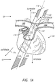
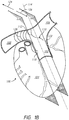
- FIG. 1A provides a perspective view of the heart 100 as seen from the front of the patient (viewed in an anterior to posterior direction), while Figure 1B provides a perspective view of the heart 100 as seen from the right side of the patient.
- the heart 100 includes the pulmonary trunk 102 that begins at the base of the right ventricle 104.
- the pulmonary trunk 102 is a tubular structure approximately 3 centimeters (cm) in diameter and 5 cm in length.
- the pulmonary trunk 102 branches into the left pulmonary artery 106 and the right pulmonary artery 108 at a branch point 110.
- the left pulmonary artery 106 and the right pulmonary artery 108 serve to deliver de-oxygenated blood to each corresponding lung.
- the branch point 110 includes a ridge 112 that extends from the posterior of the pulmonary trunk 102. As illustrated, the branch point 110, along with the ridge 112, provides a "Y" or "T" shaped structure that helps to define at least a portion of the left pulmonary artery 106 and the right pulmonary artery 108. For example, from the ridge 112, the branch point 110 of the pulmonary trunk 102 slopes in opposite directions. In a first direction, the pulmonary trunk 102 transitions into the left pulmonary artery 106, and in the second direction, opposite the first direction, the pulmonary trunk 102 transitions into the right pulmonary artery 108.
- the branch point 110 may not necessarily be aligned along a longitudinal center line 114 of the pulmonary trunk 102.
- portions of the pulmonary artery 102 can be defined with a right lateral plane 116 that passes along a right luminal surface 118 of the pulmonary trunk 102, a left lateral plane 120 parallel with the right lateral plane 116, where the left lateral plane 120 passes along a left luminal surface 122 of the pulmonary artery 102.
- the right lateral plane 116 and the left lateral plane 120 extend in both a posterior direction 124 and anterior direction 126.
- the ridge 112 of the branch point 110 is located between the right lateral plane 116 and the left lateral plane 120.
- the branch point 110 is positioned between the right lateral plane 116 and the left lateral plane 120, where the branch point 110 can help to at least partially define the beginning of the left pulmonary artery 106 and the right pulmonary artery 108 of the heart 100.
- the distance between the right lateral plane 116 and the left lateral plane 120 is approximately the diameter of the pulmonary trunk 102 (e.g., about 3 cm).
- the present disclosure includes methods for electrical neuromodulation of the heart 100 of the patient.
- a catheter positioned in the pulmonary artery 102 of the patient can be used to deliver one or more electrical pulses to the heart 100.
- a first sensor for example as discussed herein, positioned at a first location within the vasculature of the heart 100 senses one or more heart activity properties (e.g., non-electrical heart activity properties) in response to the one or more electrical pulses.
- Heart activity properties e.g., non-electrical heart activity properties
- Properties of the one or more electrical pulses delivered through the catheter positioned in the pulmonary artery 102 of the heart 100 can then be adjusted in response to the one or more heart activity properties in an effort to provide adjuvant cardiac therapy to the patient.
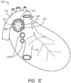
- Figure 1C provides an additional illustration the posterior surface 121, the superior surface 123, and the inferior surface 125 of the right pulmonary artery 108.
- the view of the heart 100 in Figure 1C is from the right side of the heart 100.
- the posterior surface 121, the superior surface 123, and the inferior surface 125 account for approximately three quarters of the luminal perimeter of the right pulmonary artery 108, where the anterior surface 127 accounts for the remainder.
- Figure 1C also illustrates the aorta 130, pulmonary veins 132, the superior vena cava (SVC) 134, and the inferior vena cava (IVC) 136.
- SVC superior vena cava
- IVC inferior vena cava
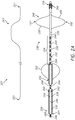
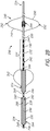
- the catheter 230 includes an elongate catheter body 232 having a proximal or first end 234 and a distal or second end 236.
- the elongate catheter body 232 also includes an outer or peripheral surface 238 and an interior surface 240 defining a lumen 242 (shown with a broken line) that extends between the first end 234 and the second end 236 of the elongate catheter body 232.
- the catheter 230 further includes a plurality of electrodes 244 positioned along the peripheral surface 238 of the elongate catheter body 232. In some embodiments, the electrodes 244 are proximate to a distal end 236 of the catheter 230.
- Conductive elements 246 extend through the elongate body 232, where the conductive elements 246 can be used, as discussed herein, to conduct electrical pulses to combinations of the plurality of electrodes 244.
- Each of the plurality of electrodes 244 is coupled (e.g., electrically coupled) to a corresponding conductive element 246.
- the conductive elements 246 are electrically isolated from each other and extend through the elongate body 232 from each respective electrode 244 through the first end 234 of the elongate body 232.
- the conductive elements 246 terminate at a connector port, where each of the conductive elements 246 can be releasably coupled to a stimulation system. It is also possible that the conductive elements 246 are permanently coupled to the stimulation system (e.g., not releasably coupled). As discussed more fully herein, the stimulation system can be used to provide stimulation electrical pulses that are conducted through the conductive elements 246 and delivered across combinations of the plurality of electrodes 244. Other positions and configurations of electrodes are also possible, for example the electrodes described in the applications incorporated herein by reference (e.g., the electrodes on deployable filaments such as described in PCT Patent App. Nos. PCT/US2015/031960 and PCT/US2015/047770 , the electrode matrix such as described in PCT Patent App. Nos. PCT/US2015/047770 and PCT/US2015/047780 , and others).
- the electrodes described in the applications incorporated herein by reference e.g., the electrodes on deployable filaments such as described
- the elongate body 232 may comprise (e.g., be at least partially formed of) an electrically insulating material.
- an electrically insulating material can include, but are not limited to, medical grade polyurethanes, such as polyester-based polyurethanes, polyether-based polyurethanes, and polycarbonate-based polyurethanes; polyamides, polyamide block copolymers, polyolefins such as polyethylene (e.g., high density polyethylene); and polyimides, among others.
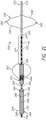
- the catheter 230 optionally includes an anchor 248.
- the anchor 248 includes struts 250 that form an open framework, where the struts 250 extend laterally or radially outwardly from the elongate body 232 (e.g., from a peripheral surface 238 of the elongate body 232) to at least partially define a peripheral surface 252 configured to engage vascular tissue (e.g., configured to appose sidewalls forming the lumen of the right pulmonary artery and/or the left pulmonary artery).
- Figures 2A through 2C show the anchor 248 positioned between the second end 236 and the plurality of electrodes 244 of the elongate catheter body 232.
- the anchor 248 can be positioned between the plurality of electrodes 244 and the second end 236 of the elongate catheter body 232.
- the anchor 248 can inhibit or prevent at least a portion of the catheter 230 (e.g., the portion 254, a portion comprising the electrodes 244) from extending into vasculature smaller than the expanded struts 250.
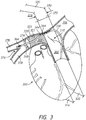
- the plurality of electrodes 344 can be proximal to the branch point 310 such that portions of the catheter 330 proximal to the anchor 348 do not extend into the two additional arteries 378. If the sensor 366 is distal to the anchor 348, interaction of the anchor 348 and the branch point 310 may ensure that the sensor 366 is in a pulmonary artery branch vessel 378.
- the struts 250 can have a cross-sectional shape and dimension that allow for the struts 250 to provide a radial force sufficient to hold the catheter 230 at the implant location within the pulmonary artery under a variety of situations, as discussed herein.
- the struts 250 can be formed of a variety of materials, such as a metal, metal alloy, polymer, etc. Examples of such metals or metal alloys include surgical grade stainless steel, such as austenitic 316 stainless among others, and the nickel and titanium alloy known as Nitinol. Other metals and/or metal alloys, as are known or may be developed, can be used.
- a portion 254 of the elongate catheter body 232 can curve in a predefined radial direction (e.g., anterior, posterior, inferior, superior, and combinations thereof), for example when placed under longitudinal compression.
- a predefined radial direction e.g., anterior, posterior, inferior, superior, and combinations thereof
- the elongate catheter body 232 can be pre-stressed and/or the wall can have thicknesses that allow for the elongate catheter body 232 to curve in the predefined radial direction, for example when placed under longitudinal compression.
- structures such as coils or a helix of wire having different turns per unit length, a hypotube having varying kerf spacing, etc.
- the anchor 248 can be deployed in the vasculature of the patient (e.g., in the pulmonary artery), where the anchor 248 provides a location or point of resistance against the longitudinal movement of the elongate body 232. As such, this allows a compressive force to be generated in the elongate catheter body 232 sufficient to cause the portion 254 of the elongate catheter body 232, for example along which the plurality of electrodes 244 are present, to curve in the predefined radial direction.
- Figure 2D provides an illustration of the portion 254 of the elongate catheter body 232 curved in a predefined radial direction when placed under longitudinal compression.
- the catheter 230 illustrated in Figure 2D is similar to the catheter 230 shown in Figure 2A and is described herein, although other catheters having similar features can also be used.
- the sensor 266 is proximal to the electrodes 244. When the electrodes are in the right pulmonary artery 208, the sensor 266 can be in the pulmonary trunk 202, for example. If the sensor 266 is more proximal, the sensor 266 can be in the right ventricle, the superior vena cava, etc.
- Positioning the sensor 266 proximal along the catheter 230 can allow the sensor 266 to be in a location different than the location of the electrode 244 without positioning the sensor 266 separate from positioning the electrode 244.
- the catheter 230 has been at least partially positioned within the main pulmonary artery 202 of a patient's heart 200, where the anchor 248 is located in the lumen of the right pulmonary artery 208. From this position, a longitudinal compressive force applied to the elongate catheter body 232 can cause the portion 254 of the elongate catheter body 232, along with at least some of the plurality of electrodes 244 in this embodiment, to curve in the predefined radial direction, superior in this embodiment.
- the curvature allows the plurality of electrodes 244 to extend towards and/or touch the luminal surface of the main and/or right pulmonary artery.
- the plurality of electrodes 244 are brought into position and/or contact with the luminal surface of the main and/or right pulmonary artery.
- the elongate catheter body 232 of the catheter 230 can use the lumen 242 that extends from the first end 234 towards the second end 236 to provide a curve in a predefined radial direction.
- the catheter 230 can include a shaping wire 257 having a first end 259 and a second end 261, as illustrated in Figure 2A .
- the shaping wire 257 can be bent and retain a desired shape that, upon insertion into the lumen 242, can at least partially provide the catheter 230 with a curve.
- the lumen 242 has a size (e.g., a diameter) sufficient to allow the shaping wire 257 to pass through the lumen 242 with the second end 261 of the shaping wire 257 proximate to the second end 236 of the elongate catheter body 232 so that the bent portion 263 of the shaping wire 257 imparts a curve into the portion 254 of the elongate catheter body 232, allowing the plurality of electrodes 244 to extend towards and/or touch the luminal surface of the main pulmonary artery.
- the shaping wire 257 can complement the portion 254.
- the shaping wire 257 can be used in place of the portion 254 (e.g., if the catheter 230 does not include the portion 254 or by not imparting the longitudinal compressive force). In some embodiments, the shaping wire 257 can be used to impart a curve that is contrary to the curve that the portion 254 would cause if a compressive force was applied. In some embodiments, the shaping wire 257 may be inserted into the lumen 242 in any rotational orientation such that a curve can be imparted in any desired radial direction, for example depending on the position of the anchor 248.
- the shaping wire 257 can allow formation of a curve even if the catheter 230 does not include an anchor 248, for example because the catheter body 232 can conform to the shape of the shaping wire regardless of whether the catheter 230 is anchored to the vasculature.
- insertion of the shaping wire 257 into the lumen 242 imparts a curve to the portion 254 such that at least one of the electrodes 244 apposes a superior/posterior sidewall of the pulmonary artery.
- a neuromodulation system comprises a catheter 230 and a shaping wire 257.
- the catheter 230 comprises a catheter body 232, an electrode 244, and a sensor 266.
- the catheter body 232 comprises a proximal end 234, a distal end 236, a lumen 242 extending from the proximal end 234 towards the distal end 236 (e.g., at least distal to the electrode 244), and an outer surface 238.
- the electrode 244 is on the outer surface 238.
- the electrode 244 is configured to deliver an electrical signal to a pulmonary artery of a patient (e.g., to provide calibration and/or therapeutic stimulation to a nerve proximate the pulmonary artery).
- the shaping wire 257 comprises a material that is configured to cause the catheter body 232 to bend.
- the radial force of the shaping wire 257 may be greater than the forces that keep the catheter body 232 in a generally straight configuration.
- the shaping wire 257 comprises a shape memory material (e.g., nitinol, chromium cobalt, copper aluminum nickel, etc.) or a resilient material (e.g., stainless steel, etc.).
- the shaping wire 257 may be stressed to a straight wire in a proximal portion of the catheter 230, but in a portion of the catheter 230 to be bent, which may be, for example, weaker that the proximal portion of the catheter 230, the shaping wire 257 can revert to the unstressed curved shape within the catheter 230.
- the shaping wire 257 may utilize thermal shape memory.
- the shaping wire 257 may be in a substantially straight shape until cold or warm fluid (e.g., saline) causes reversion to the curved shape.
- the entire catheter 230 may be bendable by the shaping wire 257, but the temperature change is effected once the shaping wire 257 is in a desired longitudinal and/or radial position.
- the entire catheter 230 may be bendable by the shaping wire 257.
- the curve may propagate along the length of the catheter 230 until the curve is in a desired position.
- the shaping wire 257 has a diameter or cross-sectional dimension less than the diameter or cross-sectional dimension of the lumen 242.
- the lumen 242 may be 18 Fr (approx. 6 mm) and the shaping wire 257 may be 16 Fr (approx. 5.33 mm).
- the shaping wire 257 may be, for example 1 Fr less than the lumen 242 (e.g., for more radial force than if 2 Fr less) or 2 Fr less than the lumen 242 (e.g., for less friction during navigation than if 1 Fr less).
- the shaping wire 257 may be, for example 2 Fr less than the catheter body 232 (e.g., if the lumen 242 is 1 Fr less than the catheter body 232) or 4 Fr less than the catheter body 232 (e.g., providing flexibility for the size of the lumen 242 to be 1 or 2 Fr less than the catheter body).
- Shaping wire sizes other than on a French catheter scale are also possible (e.g., having a diameter less than a diameter of the lumen 242 by about 0.05 mm, 0.1 mm, by about 0.2 mm, by about 0.25 mm, by about 0.5 mm, ranges between such values etc.).
- the sensor 266 is on the outer surface 238.
- the sensor 266 is configured to sense a heart activity property (e.g., a non-electrical heart activity property such as a pressure property, an acceleration property, an acoustic property, a temperature, and a blood chemistry property) from a location within in vasculature of the patient.
- a heart activity property e.g., a non-electrical heart activity property such as a pressure property, an acceleration property, an acoustic property, a temperature, and a blood chemistry property
- the location may be different than the pulmonary artery in which the electrode 244 is positioned.
- the location of the sensor 266 may be in the pulmonary trunk, a pulmonary artery branch vessel, the right ventricle, the ventricular septal wall, the right atrium, the septal wall of the right atrium, the superior vena cava, the inferior vena cava, the left pulmonary artery, the coronary sinus, etc.
- the shaping wire 257 is configured to be positioned in the lumen 242 of the catheter body 232. The shaping wire comprising a bent portion 263.
- the shaping wire 257 may be substantially straight in a substantially straight portion, then have a bent portion 263 extending away from a longitudinal axis of the straight portion.
- the bent portion 263 may include one bend or a plurality of bends (e.g., two bends (as illustrated in Figure 2A ), three bends, or more bends).
- the shaping wire 257 may optionally comprise another substantially straight portion after the bent portion, which may have a longitudinal axis that is substantially aligned with the longitudinal axis of the proximal straight portion.
- the catheter body 232 When the shaping wire 257 is inserted in the lumen 242 of the catheter body 232, the catheter body 232 comprises a curved portion 254 corresponding to the bent portion 263 of the shaping wire 257.
- the catheter body 232, or the portion 254 may comprise a material that can be bent due to pressure or stress applied to the lumen 242 or interior surface 240 of the catheter body 232.
- insertion of the shaping wire 257 into the lumen 242 imparts a curve to the portion 254 such that at least one of the electrodes 244 apposes a superior/posterior sidewall of the pulmonary artery.
- FIGS. 2A through 2C further illustrate an example delivery catheter 256 that can be used in conjunction with the catheter 230.
- the delivery catheter 256 can be a Swan-Ganz type pulmonary artery catheter, as are known, that includes a surface 258 defining a lumen 260 sized sufficiently to receive, store, and deploy the catheter 230.
- the delivery catheter 256 includes a reversibly inflatable balloon 262 in fluid communication with a balloon inflation lumen that extends from a proximal or first end 264 of the delivery catheter 256 (e.g., where the inflation lumen can be to an inflation fluid source) to the interior volume of the reversibly inflatable balloon 262.
- the catheter 230 also includes a first sensor 266. As illustrated in Figures 2A through 2C , the first sensor 266 can be positioned at a number of different locations along the catheter 230. In Figure 2A , the first sensor 266 is positioned on the elongate catheter body 232 distal to the anchor 248. A sensor 266 that is proximate to the distal end 236 of the catheter 230 may also or alternatively be useful for navigation of the catheter 230, for example to determine an anatomical location during floating a balloon such as with a Swan-Ganz catheter. In Figure 2B , the first sensor 266 is positioned on or between one of the struts 250 of the anchor.
- the first sensor 266 is positioned proximal to both the anchor 248 and the plurality of electrodes 244.
- the first sensor 266 is positioned proximal enough that the first sensor 266 can be in a location of the vasculature different than the electrodes 244.
- the catheter 230 comprises a plurality of sensors 266 at more than one of the positions illustrated in Figures 2A through 2C and/or other positions.
- the catheter 230 further includes a sensor conductor 268.
- the first sensor 266 is coupled to the sensor conductor 268 and is isolated from the conductive elements 246 and electrodes 244. The coupling may be electrical, optical, pressure, etc.
- the sensor conductor 268 extends through the elongate body 232 from the first sensor 266 through the first end 234 of the elongate body 232.
- the sensor conductor 268 terminates at a connector port that can be used, for example, to releasably couple the first sensor 266 to the stimulation system, as discussed herein.
- the first sensor 266 can be used to sense one or more activity property (e.g., electrical and/or non-electrical heart activity properties).
- the property can be measured in response to one or more electrical pulses delivered using the plurality of electrodes 244.
- non-electrical heart activity properties include, but are not limited to, one or more of a pressure property, an acceleration property, an acoustic property, a temperature, and a blood chemistry property measured from within the vasculature of the heart.
- two or more of the non-electrical heart activity properties can be measured by using more than one sensor on the catheter 230.
- the first sensor 266 can be a pressure sensing transducer, for example such as disclosed in U.S. Patent No. 5,564,434 (e.g., configured to detect changes in blood pressure, atmospheric pressure, and/or blood temperature and to provide modulated pressure and/or temperature related signals), incorporated by reference herein in its entirety.
- the first sensor 266 can be an acceleration sensor, for example such as disclosed in U.S. Patent Pub. No. 2004/0172079 to Chinchoy (e.g., configured to generate a signal proportional to acceleration of a heart muscle or wall such as a coronary sinus wall, septal wall, or ventricle wall) or U.S.
- Patent 7,092,759 to Nehls et al. e.g., configured to generate a signal proportional to acceleration, velocity, and/or displacement of a heart muscle or wall such as a coronary sinus wall, septal wall, or ventricle wall
- the first sensor 266 can be a piezoelectric transducer (e.g., a microphone) or a blood flow sensor, for example such as disclosed in U.S. Patent No. 6,754,532 (e.g., configured to measure a velocity of blood to estimate blood flow volume), which is incorporated by reference herein in its entirety.
- the first sensor 266 can be a temperature sensor, for example such as disclosed in U.S. Patent No. 5,336,244 (e.g., configured to detect variations in blood temperature and/or oxygen concentration indicative of the mechanical pumping action of the heart) and/or U.S. Patent Pub. No. 2011/0160790 (e.g., configured to sense temperature and to produce a temperature signal), each of which is incorporated by reference herein in its entirety.
- the first sensor 266 can be an oxygen sensor or a glucose sensor, for example such as disclosed in U.S. Patent No.
- the catheter 230 shown in Figures 2A through 2C can be positioned in the right pulmonary artery, the left pulmonary artery, or the pulmonary trunk of the patient, as described herein.
- the delivery catheter 256 with the catheter 230 housed therein can be introduced into the vasculature through a percutaneous incision, and guided to the right ventricle using known techniques.
- the delivery catheter 256 can be inserted into the vasculature via a peripheral vein of the neck or chest (e.g., as with a Swan-Ganz catheter). Changes in a patient's electrocardiography and/or pressure signals from the vasculature can be used to guide and locate the pulmonary artery catheter within the patient's heart.
- a guide wire can be introduced into the patient via the pulmonary artery guide catheter, where the guide wire is advanced into the desired pulmonary artery (e.g., the right pulmonary artery).
- the delivery catheter 256 with the catheter 230 housed therein can be advanced over the guide wire so as to position the catheter 230 in the desired pulmonary artery of the patient (e.g., the right pulmonary artery or the left pulmonary artery), as described herein.
- Various imaging modalities can be used in positioning the guide wire of the present disclosure in the pulmonary artery of the patient.
- imaging modalities include, but are not limited to, fluoroscopy, ultrasound, electromagnetic, and electropotential modalities.
- a distance between the electrodes 244 (e.g., from the proximal-most electrode 244) and the sensor 266 may be between about 1 cm and about 5 cm (e.g., about 1 cm, about 2 cm, about 3 cm, about 4 cm, about 5 cm, ranges between such values, etc.), in which case the sensor 266 can reside in the pulmonary trunk, between about 8 cm and about 20 cm (e.g., about 8 cm, about 9 cm, about 10 cm, about 11 cm, about 12 cm, about 13 cm, about 14 cm, about 16 cm, about 18 cm, about 20 cm, ranges between such values, etc.), in which case the sensor 266 can reside in the right ventricle, between about 16 cm and about 27 cm (e.g., about 16 cm, about 17 cm, about 18 cm, about 19 cm, about 20 cm, about 21 cm, about 22 cm, about 23
- a distance between the electrodes 244 (e.g., from the distal-most electrode 244) and the sensor 266 may be between about 1 cm and about 5 cm (e.g., about 1 cm, about 2 cm, about 3 cm, about 4 cm, about 5 cm, ranges between such values, etc.), in which case the sensor 266 can reside in the right pulmonary artery or the left pulmonary artery.
- a distance between the electrodes 244 (e.g., from the proximal-most electrode 244) and the sensor 266 may be between about 3 cm and about 19 cm (e.g., about 3 cm, about 5 cm, about 6 cm, about 7 cm, about 8 cm, about 9 cm, about 10 cm, about 12 cm, about 15 cm, about 19 cm, ranges between such values, etc.), in which case the sensor 266 can reside in the right ventricle, between about 11 cm and about 26 cm (e.g., about 11 cm, about 13 cm, about 15 cm, about 16 cm, about 17 cm, about 18 cm, about 19 cm, about 20 cm, about 22 cm, about 24 cm, about 26 cm, ranges between such values, etc.), in which case the sensor 266 can reside in the right atrium, or between about 16 cm and about 32 cm (e.g., about 16 cm, about 18 cm, about 20 cm, about 22
- Figure 3 provides a perspective view of the catheter 330 positioned in the heart 300 of the patient, where one or more of the plurality of electrodes 344 are contacting the posterior 321 and/or superior surface 323 of the right pulmonary artery 308 (e.g., at a position that is superior to the branch point 310).
- Figure 3 further illustrates the embodiment in which the first sensor 366 is positioned distal from the anchor 348.
- the pulmonary trunk 302 has a diameter 370 taken across a plane 372 substantially perpendicular to both the left lateral plane 320 and the right lateral plane 316.
- the plurality of electrodes 344 of the catheter 330 is positioned in an area 374 that extends distally no more than about three times the diameter 370 of the pulmonary trunk 302 to the right of the branch point 310.
- This area 374 is shown with cross-hatching in Figure 3 .
- the right pulmonary artery 308 can also include a branch point 376 that divides the right pulmonary artery 308 into at least two additional arteries 378 that are distal to the branch point 310 defining the left pulmonary artery 306 and the right pulmonary artery 308.
- the plurality of electrodes 344 can be positioned between the branch point 310 defining the left pulmonary artery 306 and the right pulmonary artery 308 and the branch point 376 that divides the right pulmonary artery 308 into at least two additional arteries 378.
- the plurality of electrodes 344 of the catheter 330 could be positioned so as to contact the posterior 321 and/or superior surface 323 of the right pulmonary artery 308 up to an including the branch point 376.
- one or more therapeutic and/or calibrating electrical pulses can be delivered through the plurality of electrodes 344 of the catheter 330.
- One or more heart activity properties in response to the one or more electrical pulses are sensed from at least the first sensor 366 positioned at a first location within the vasculature of the heart 300.
- the catheter 230, 330 may be permanently or reversibly implantable into the vasculature.
- the catheter 230, 330 may be retracted from the vasculature (e.g., after removing the anchor 248, 348) after a duration.
- the duration may be determined based at least partially on a set duration (e.g., a certain number of hours or days (e.g., 12 hours, 18 hours, 24 hours, 2 days, 3 days, 4 days, 5 days, 6 days, etc.)).
- the duration may be determined based at least partially on a response of a patient (e.g., retracted when the patient has improved in an aspect by a certain amount or is deemed ready to have the catheter 230, 330 removed).
- Figure 4 illustrates an example catheter 430 and a separate first sensor 466 useful for the methods of the present disclosure.
- the catheter 430 includes an elongate catheter body 432 having a proximal or first end 434 and a distal or second end 436, a peripheral surface 438 and an interior surface 440 defining a lumen 442 (shown with a broken line) that extends between the first end 434 and the second end 436 of the elongate catheter body 432.
- the catheter 430 further includes a plurality of electrodes 444 positioned along the peripheral surface 438 of the elongate catheter body 432, and conductive elements 446 extending through the elongate body 432 between the plurality of electrodes 444 and the first end 434, as discussed herein.
- the catheter 430 further includes an anchor 448 comprising struts 450 that provide a peripheral surface 452 that can engage vascular tissue (e.g., the lumen of either the right pulmonary artery or the left pulmonary artery).
- the catheter 430 further includes a portion 454 of the elongate catheter body 432, for example including the plurality of electrodes 444, where the portion 454 can curve in a predefined radial direction when placed under longitudinal compression, as discussed herein.
- the elongate catheter body 432 of the catheter 430 can also or alternatively include a lumen 442 that can receive a shaping wire, as discussed herein.
- the catheter 430 does not include a first sensor. Rather, a second catheter 480 includes a first sensor 466. As illustrated in Figure 4 , the second catheter 480 includes an elongate catheter body 482 having a first end 484 and a second end 486, a peripheral surface 488 and an interior surface 490 defining a lumen 492 (shown with a broken line) that extends between the first end 484 and the second end 486 of the elongate catheter body 482, where the lumen 492 can receive a guide wire for help in positioning the second catheter 480 in the vasculature of the heart.
- a lumen 492 shown with a broken line
- the second catheter 480 further includes a first sensor 466, as discussed herein, on the elongate catheter body 482 and a sensor conductor 468 that extends through the elongate catheter body 482 to terminate at a connector port that can be used, for example, to releasably couple the first sensor 466 to the stimulation system, as discussed herein.
- the first sensor 466 can be positioned in a location within the vasculature of the patient that is different than the first location in which the catheter 430 is positioned.
- the catheter 430 can be positioned with the plurality of electrodes 444 positioned in the right pulmonary artery, as discussed herein, while the first sensor 466 is positioned in the left pulmonary artery. In this way, one or more electrical pulses can be delivered through the catheter 430 positioned in the right pulmonary artery of the heart that does not contain the first sensor 466.
- the first sensor 466 can be positioned in the right pulmonary artery. In this way, one or more electrical pulses can be delivered through the catheter 430 positioned in the left pulmonary artery of the heart that does not contain the first sensor 466.
- the catheter 430 can be positioned with the plurality of electrodes 444 positioned in either one of the left pulmonary artery or the right pulmonary artery, and the first sensor 466 on the second catheter 480 can be positioned in the right ventricle of the heart.
- the first sensor 466 on the second catheter 480 can also be positioned in the right atrium of the heart.
- the first sensor 466 on the second catheter 480 can also be positioned on the septal wall of the right atrium or the ventricular septal wall of the heart.
- the elongate catheter body 482 of the second catheter 480 can include a positive fixation structure (e.g., a helical screw) that helps to secure the elongate catheter body 482 and the first sensor 466 to the septal wall of the right atrium of the heart.
- the first sensor 466 on the second catheter 480 can be positioned in a superior vena cava of the heart. In some embodiments, the first sensor 466 on the second catheter 480 can be positioned in an inferior vena cava of the heart. In some embodiments, the first sensor 466 on the second catheter 480 can be positioned in a coronary sinus of the heart. In a preferred embodiment, when the first sensor 466 is positioned in the coronary sinus of the heart, the first sensor 466 is used to sense at least one of a temperature and a blood oxygen level.
- One or more cardiac properties can also or alternatively be sensed from a skin surface of the patient.
- An example of such a cardiac property includes an electrocardiogram property, where the electrical activity of the heart can be sensed using electrodes, as are known, attached to the surface of the patient's skin.
- Another example of such a cardiac property can include a doppler echocardiogram, which can be used to determine the speed and direction of the blood flow.
- Acoustic signals sensed from the skin surface of the patient may also be used as the cardiac property.
- the properties of the one or more electrical pulses delivered through the catheter positioned in the pulmonary artery of the heart can then be adjusted, as discussed herein, in response to the one or more heart activity properties measured intravascularly and/or the one or more cardiac properties from the skin surface of the patient.
- a second sensor located at a second location within the vasculature of the heart can be used, in addition to the first sensor, to sense one or more heart activity properties, as discussed herein, for example in response to the one or more electrical pulses.
- the second location is different than the first location.
- the first location may be the left pulmonary artery and the second location may be the right pulmonary artery; the first location may be the left pulmonary artery and the second location may be the pulmonary trunk; the first location may be the left pulmonary artery and the second location may be the right ventricle; the first location may be the left pulmonary artery and the second location may be the right atrium; the first location may be the left pulmonary artery and the second location may be the septal wall of the right atrium; the first location may be the left pulmonary artery and the second location may be the ventricular septal wall; the first location may be the left pulmonary artery and the second location may be the superior vena cava; the first location may be the left pulmonary artery and the second location may be the inferior vena cava; the first location may be the left pulmonary artery and the second location may be the coronary sinus; and other permutations of these locations.
- the second sensor is the sensor 466 of the second catheter 480
- the first sensor is the sensor 266 of the catheter 230
- the first sensor and the second sensor can be located on the same catheter (e.g., the catheter 230, the catheter 480).
- both the first sensor and the second sensor can be located on the second catheter 480 for sensing at least two different heart activity properties.
- both the first sensor and the second sensor can be located on the catheter 230 for sensing at least two different heart activity properties.
- the properties of the one or more electrical pulses delivered through the catheter positioned in the pulmonary artery of the heart can be adjusted, as discussed herein, in response to the one or more heart activity properties received from the first sensor and the second sensor.
- Neuromodulation of the heart according to the present disclosure can be accomplished by applying electrical pulses in and/or around the region of the pulmonary artery.
- the neuromodulation of the present disclosure can apply the electrical pulses to the posterior, superior wall, and/or the inferior wall of the right pulmonary artery.
- neuromodulation of the present disclosure includes applying the electrical pulses to the posterior and/or superior wall of the right pulmonary artery, although other positions in the right pulmonary artery, the left pulmonary artery, and the pulmonary trunk are also possible.
- the electrical pulses are thereby applied to the autonomic cardiopulmonary nerves surrounding the right pulmonary artery.
- These autonomic cardiopulmonary nerves can include the right autonomic cardiopulmonary nerves and the left autonomic cardiopulmonary nerves.
- the right autonomic cardiopulmonary nerves include the right dorsal medial cardiopulmonary nerve and the right dorsal lateral cardiopulmonary nerve.
- the left autonomic cardiopulmonary nerves include the left ventral cardiopulmonary nerve, the left dorsal medial cardiopulmonary nerve, the left dorsal lateral cardiopulmonary nerve, and the left stellate cardiopulmonary nerve. Stimulation of other nerves proximate to the right pulmonary artery is also possible.
- one or more of the plurality of electrodes 344 of the catheter 330 can be contacting the posterior surface 321 of the right pulmonary artery 308. From this location, the electrical pulses delivered through one or more of the plurality of electrodes 344 may be better able to treat and/or provide therapy (including adjuvant therapy) to the patient experiencing a variety of cardiovascular medical conditions, such as acute heart failure.
- the electrical pulses can elicit responses from the autonomic nervous system that may help to modulate a patient's cardiac contractility.
- the electrical pulses applied by the methods described herein preferably affect heart contractility more than the heart rate, which can help to improve hemodynamic control while possibly and/or reducing or minimizing unwanted systemic effects.
- a stimulation system is electrically coupled to the plurality of electrodes of the catheter via the conductive elements extending through the catheter.
- the stimulation system can be used to deliver the electrical pulses to the autonomic cardiopulmonary fibers surrounding the pulmonary artery (e.g., the right pulmonary artery).
- the stimulation system is used to operate and supply the electrical pulses to the plurality of electrodes of the catheter.
- the stimulation system controls the various properties of the electrical pulses delivered across the plurality of electrodes.
- Such properties include control of polarity (e.g., used as a cathode or an anode), pulsing mode (e.g., unipolar, bi-polar, biphasic, and/or multi-polar), a pulse width, an amplitude, a frequency, a phase, a voltage, a current, a duration, an inter-pulse interval, a dwell time, a sequence, a wavelength, and/or a waveform associated with the electrical pulses.
- the stimulation system may operate and supply the electrical pulses to different combinations and numbers of the plurality of electrodes, including a reference electrode.
- the stimulation system can be external to the patient's body or internal to the patient's body. When located outside the body, a professional can program the stimulation system and monitor its performance. When located within the patient, the housing of the stimulation system or an electrode incorporated in the housing can be used as a reference electrode for both sensing and unipolar pulsing mode.
- non-electrical heart activity properties include, but are not limited to, a pressure property, an acceleration property, an acoustic property, a temperature, or a blood chemistry property.
- the non-electrical heart activity properties may be sensed by at least a first sensor positioned at a first location within the vasculature of the heart.
- a property of the one or more electrical pulses delivered through the catheter positioned in the pulmonary artery of the heart can be adjusted. Examples of such adjustments include, but are not limited to, changing which electrode or electrodes of the plurality of electrodes on the catheter is/are used to deliver one or more electrical pulses.
- Adjustments can also be made to the properties of the electrical pulses, for example by changing at least one of an electrode polarity, a pulsing mode, a pulse width, an amplitude, a frequency, a phase, a voltage, a current, a duration, an inter-pulse interval, a duty cycle, a dwell time, a sequence, a wavelength, and a waveform of the one or more electrical pulses. It is possible to adjust combinations of electrodes used and the properties of the electrical pulses provided by the electrodes. Adjusting a property of the one or more electrical pulses can include moving the catheter to reposition electrodes of the catheter in the pulmonary artery of the heart. Combinations of these adjustments are also possible.
- the electrical pulses can have a voltage between about 0.1 microvolts (mV) and about 75 volts (V) (e.g., about 0.1 mV, about 0.5 mV, about 1 mV, about 10 mV, about 100 mV or about 0.1 V, about 1 V, about 10 V, about 20 V, about 30 V, about 40 V, about 50 V, about 60 V, about 75 V, ranges between such values, etc.).
- V microvolts
- V e.g., about 0.1 mV, about 0.5 mV, about 1 mV, about 10 mV, about 100 mV or about 0.1 V, about 1 V, about 10 V, about 20 V, about 30 V, about 40 V, about 50 V, about 60 V, about 75 V, ranges between such values, etc.
- the electrical pulses can also have an amplitude between about 1 milliamps (mA) to about 40 mA (e.g., about 1 mA, about 2 mA, about 3 mA, about 4 mA, about 5 mA, about 10 mA, about 15 mA, about 20 mA, about 25 mA, about 30 mA, about 35 mA, about 40 mA, ranges between such values, etc.).
- mA milliamps
- the electrical pulses can be delivered at a frequency of between 1 Hertz (Hz) and about 10,000 Hz or 10 kilohertz (kHz) (e.g., about 1 Hz, about 2 Hz, about 10 Hz, about 25 Hz, about 50 Hz, about 75 Hz, about 100 Hz, about 150 Hz, about 200 Hz, about 250 Hz, about 500 Hz, about 1,000 Hz or 1 kHz, about 10 kHz, ranges between such values, etc.).
- Hz Hertz
- the electrical pulses can have a pulse width between about 100 microseconds ( ⁇ s) and about 100 milliseconds (ms) (e.g., about 100 ⁇ s, about 200 ⁇ s, about 500 ⁇ s, about 1,000 ⁇ s or 1 ms, about 10 ms, about 50 ms, about 100 ms, ranges between such values, etc.).
- ⁇ s microseconds
- ms milliseconds
- the electrical pulses may be delivered for between about 250 ms and about 1 second (e.g., about 250 ms, about 300 ms, about 350 ms, about 400 ms, about 450 ms, about 500 ms, about 550 ms, about 600 ms, about 650 ms, about 700 ms, about 750 ms, about 800 ms, about 850 ms, about 900 ms, about 950 ms, ranges between such values, etc.), and thereafter not delivered for between about 1 second and about 10 minutes (e.g., about 1 second, about 5 seconds, about 10 seconds, about 15 seconds, about 30 seconds, about 45 seconds, about 1 minute, about 2 minutes, about 3 minutes, about 5 minutes, about 10 minutes, ranges between such values, etc.).
- about 1 second and about 10 minutes e.g., about 1 second, about 5 seconds, about 10 seconds, about 15 seconds, about 30 seconds, about 45 seconds, about 1 minute, about 2 minutes, about 3 minutes, about
- An optimized duty cycle may, for example, reduce response time, increase battery life, patient comfort (reduce pain, cough, etc.), etc.
- the electrical pulses can also have a variety of waveforms, such as: square wave, biphasic square wave, sine wave, arbitrary defined waveforms that are electrically safe, efficacious, and feasible, and combinations thereof.
- the electrical pulses may be applied to multiple target sites via multiple electrodes at least partially simultaneously and/or sequentially.
- the methods of the present disclosure can include assigning a hierarchy of electrode configurations from which to deliver the one or more electrical pulses.
- the hierarchy can include two or more predetermined patterns and/or combinations of the plurality of electrodes to use in delivering the one or more electrical pulses.
- the one or more electrical pulses can be delivered using the hierarchy of electrode configurations.
- a heart activity property sensed in response to the one or more electrical pulses delivered using the hierarchy of electrode configurations can be analyzed. Such an analysis can include, for example, determining which of the hierarchy of electrode configurations provide the highest contractility or relative contractility of the patient's heart. Based on this analysis, an electrode configuration can be selected to use for delivering the one or more electrical pulses through the catheter positioned in the pulmonary artery of the patient's heart.
- a method can include assigning a hierarchy to one or more properties of the one or more electrical pulses delivered through the catheter positioned in the pulmonary artery of the heart.
- the hierarchy can include providing an order of which property (e.g., electrode polarity, pulsing mode, pulse width, amplitude, frequency, phase, voltage, current, duration, inter-pulse interval, duty cycle, dwell time, sequence, wavelength, or waveform of the one or more electrical pulses) is to be changed and by how much, and for a predetermined number of electrical pulses delivered to the patient's heart.
- the predetermined number of electrical pulses can be, for example, 10 to 100 electrical pulses at a given property of the hierarchy.
- the one or more heart activity properties can be recorded for the predetermined number of the one or more electrical pulses delivered to the patient's heart for a given property of the one or more electrical pulses.
- the one or more heart activity properties sensed in response to the one or more electrical pulses can then be analyzed.
- the recorded properties for each set of predetermined numbers of pulses can be analyzed against other sets of recorded properties and/or against predetermined standards for a given heart activity properties and/or cardiac property (e.g., contractility).
- an electrode configuration can be selected to use for delivering the one or more electrical pulses through the catheter positioned in the pulmonary artery of the patient's heart.
- a current of 1 mA can be applied to an electrode for 50 electrical pulses, followed by the application of a current of 10 mA to the electrode for 50 electrical pulses.
- the responses at 1 mA and 10 mA can be compared. If 10 mA works better, a current of 20 mA can be applied to the electrode for 50 electrical pulses, and the responses at 10 mA and 20 mA can be compared. If 10 mA works better, 10 mA may be selected as the current for the method.
- selection processes may be used, including but not limited to iterative methods (e.g., comprising making comparisons until a limit is found at which a difference is negligible) and brute force methods (e.g., measuring responses and selecting one magnitude after completion of all responses or until a certain value is achieved). This can be repeated for one or more additional properties according to the hierarchy (e.g., current followed by frequency).
- the selection process may be the same or different for each member of the hierarchy.
- a first electrical signal of a series of electrical signals is delivered (e.g., via a stimulation system such as the stimulation system 501) to an electrode in the pulmonary artery (e.g., the right pulmonary artery, the left pulmonary artery, the pulmonary trunk).
- a second electrical signal of the series of electrical signals is delivered (e.g., via the stimulation system) to the electrode.
- the second electrical signal differs from the first electrical signal by a magnitude of a first parameter of a plurality of parameters.
- the first electrical signal may have a voltage such as 1 mA and the second electrical signal may have a different voltage such as 2 mA, while each of the other parameters (e.g., polarity, pulse width, amplitude, frequency, voltage, duration, inter-pulse interval, dwell time, sequence, wavelength, and waveform) are the same.
- the other parameters e.g., polarity, pulse width, amplitude, frequency, voltage, duration, inter-pulse interval, dwell time, sequence, wavelength, and waveform
- Sensor data indicative of one or more non-electrical heart activity properties may be determined in response to delivering the series of electrical signals (e.g., via a sensor in the vasculature (e.g., as part of a same catheter that comprises the electrode, as part of a different catheter), via a sensor on a skin surface, combinations thereof, and the like)).
- Electrical parameters to use for therapeutic modulation may be selected based at least partially on the sensor data.
- the selected electrical parameters may comprise a selected magnitude of the first parameter.
- a therapeutic neuromodulation signal may be delivered to the pulmonary artery using selected electrical parameters.
- the therapeutic neuromodulation signal may increase heart contractility (e.g., more than heart rate).
- a first series of electrical signals is delivered (e.g., via a stimulation system such as the stimulation system 501) to an electrode in the pulmonary artery (e.g., the right pulmonary artery, the left pulmonary artery, the pulmonary trunk).
- the first series comprises a first plurality of electrical signals.
- Each of the first plurality of electrical signals comprises a plurality of parameters (e.g., polarity, pulsing mode, pulse width, amplitude, frequency, phase, voltage, current, duration, inter-pulse interval, duty cycle, dwell time, sequence, wavelength, waveform, subsets thereof, or the like).
- Each of the first plurality of electrical signals of the first series only differs from one another by a magnitude of a first parameter of the plurality of parameters (e.g., one of polarity, pulsing mode, pulse width, amplitude, frequency, phase, voltage, current, duration, inter-pulse interval, duty cycle, dwell time, sequence, wavelength, and waveform changes in each of the first plurality of electrical signals).
- a first parameter of the plurality of parameters e.g., one of polarity, pulsing mode, pulse width, amplitude, frequency, phase, voltage, current, duration, inter-pulse interval, duty cycle, dwell time, sequence, wavelength, and waveform changes in each of the first plurality of electrical signals.
- the first plurality of electrical signals of the first series may differ by having different currents such as 1 mA, 2 mA, 3 mA, 4 mA, etc., while each of the other parameters (e.g., polarity, pulsing mode, pulse width, amplitude, frequency, phase, voltage, duration, inter-pulse interval, duty cycle, dwell time, sequence, wavelength, and waveform) are the same.
- each of the other parameters e.g., polarity, pulsing mode, pulse width, amplitude, frequency, phase, voltage, duration, inter-pulse interval, duty cycle, dwell time, sequence, wavelength, and waveform
- a second series of electrical signals can be delivered (e.g., via the stimulation system) to the electrode.
- the second series comprises a second plurality of electrical signals.
- Each of the second plurality of electrical signals comprises the plurality of parameters.
- Each of the second plurality of electrical signals of the second series only differs from one another by a magnitude of a second parameter of the plurality of parameters different than the first parameter (e.g., a different one of polarity, pulsing mode, pulse width, amplitude, frequency, phase, voltage, current, duration, inter-pulse interval, duty cycle, dwell time, sequence, wavelength, and waveform changes in each of the second plurality of electrical signals).
- the second parameter may be related to timing such as frequency or duty cycle
- the second plurality of electrical signals of the second series may differ by having different frequencies such as 1 Hz, 2 Hz, 3 Hz, 4 Hz, etc., while each of the other parameters (e.g., current, polarity, pulsing mode, pulse width, amplitude, phase, voltage, duration, inter-pulse interval, duty cycle, dwell time, sequence, wavelength, and waveform) are the same.
- Sensor data indicative of one or more non-electrical heart activity properties may be determined in response to delivering the first series of electrical signals and the second series of electrical signals (e.g., via a sensor in the vasculature (e.g., as part of a same catheter that comprises the electrode, as part of a different catheter), via a sensor on a skin surface, combinations thereof, and the like)).
- Electrical parameters to use for therapeutic modulation may be selected based at least partially on the sensor data.
- the selected electrical parameters may comprise a selected magnitude of the first parameter and a selected magnitude of the second parameter.
- a therapeutic neuromodulation signal may be delivered to the pulmonary artery using selected electrical parameters.
- the therapeutic neuromodulation signal may increase heart contractility (e.g., more than heart rate).
- Other series of electrical signals may be delivered to the electrode, for example only differing from one another by a magnitude of a different parameter of the plurality of parameters than the first parameter and the second parameter.
- a magnitude of a different parameter of the plurality of parameters may be calibrated or optimized.
- An order of the parameters may be based on a hierarchy (e.g., first select a current, then select a frequency, etc.).
- a calibration or optimization process may be performed once (e.g., when a catheter 230, 330 is initially positioned) or a plurality of times. For example, the process may be repeated periodically or after a certain duration (e.g., once per hour, per 2 hours, per 4 hours, per 6 hours, per 8 hours, per 12 hours, per 18 hours, per 24 hours, per 36 hours, per 2 days, per 60 hours, per 3 hours, etc.). In some implementations the process may be repeated upon detection of a change (e.g., by the sensor 266, 366, 466). For example, if a heart activity property changes by more than a certain percentage in a certain duration (e.g., ⁇ 10%, ⁇ 25%, ⁇ 50%, etc.
- a certain percentage in a certain duration e.g., ⁇ 10%, ⁇ 25%, ⁇ 50%, etc.
- ⁇ 1 minute, ⁇ 2 minutes, ⁇ 5 minutes, etc. may be indicative that the catheter and/or sensor changed position or that something else in the system or patient may have changed (e.g., patient condition, physiological status, other therapy regiments, etc.).
- Suitable examples of a stimulation system for use with the catheter in the method of the present disclosure can be found in U.S. Provisional Patent Application No. 62/001,729 , entitled “Catheter and Catheter System for Electrical Neuromodulation” and filed on May 22, 2014; PCT Patent Application No. PCT/US2015/179634 , entitled “Catheter and Catheter System for Electrical Neuromodulation” and filed on May 21, 2015; U.S. Provisional Patent Application No. 62/047,270 , entitled “Catheter and Electrode Systems for Electrical Neuromodulation” and filed on September 8, 2014; PCT Patent Application No. PCT/US2015/047770 , entitled “Catheter and Electrode Systems for Electrical Neuromodulation” and filed on August 31, 2015; and U.S. Patent Application No. 14/085,311 , entitled “Methods and Systems for Treating Acute Heart Failure by Neuromodulation” and filed on November 20, 2013.
- Figure 5 provides an illustration of the stimulation system similar to the stimulation system 11600 disclosed in U.S. Provisional Patent Application 62/001,729 , entitled “Catheter and Catheter System for Electrical Neuromodulation” and filed on May 22, 2014, which is hereby incorporated by reference in in its entirety, and more specifically from which Figure 11 and page 41, line 5 to page 42, line 19 are incorporated herein by reference.
- the stimulation system 501 includes an input/output connector 503 that can releasably join the conductive elements of the catheter, conductive elements of a second catheter, and/or sensors for sensing the one or more cardiac properties from the skin surface of the patient, as discussed herein.
- the conductive elements and/or sensors may be permanently coupled to the stimulation system (e.g., not releasably coupled).
- the input/output connector 503 is connected to an analog to digital converter 505.
- the output of the analog to digital converter 505 is connected to a microprocessor 507 through a peripheral bus 509 including, for example, address, data, and control lines.
- the microprocessor 507 can process the sensor data, when present, in different ways depending on the type of sensor in use.
- the microprocessor 507 can also control, as discussed herein, the pulse control output generator 511 that delivers the electrical pulses to the one or more electrodes via the input/output connector 503 and/or housing 523.
- the properties of the electrical pulses can be controlled and adjusted, if desired, by instructions programmed in a memory 513 and executed by a programmable pulse generator 515.
- the memory 513 may comprise a non-transitory computer-readable medium.
- the memory 513 may include one or more memory devices capable of storing data and allowing any storage location to be directly accessed by the microprocessor 507, such as random access memory (RAM), flash memory (e.g., non-volatile flash memory), and the like.
- the stimulation system 501 may comprise a storage device, such as one or more hard disk drives or redundant arrays of independent disks (RAID), for storing an operating system and other related software, and for storing application software programs, which may be the memory 513 or a different memory.
- RAID redundant arrays of independent disks
- the instructions in memory 513 for the programmable pulse generator 515 can be set and/or modified based on input from the sensors and the analysis of the one or more heart activity properties via the microprocessor 507.
- the instructions in memory 513 for the programmable pulse generator 515 can also be set and/or modified through inputs from a professional via an input 517 connected through the peripheral bus 509. Examples of such an input include a keyboard and/or a mouse (e.g., in conjunction with a display screen), a touch screen, etc.
- I/O input/output
- Input devices include, for example, keyboards, mice, trackpads, trackballs, microphones, and drawing tablets.
- Output devices include, for example, video displays, speakers, and printers.
- the I/O devices may be controlled by an I/O controller.
- the I/O controller may control one or more I/O devices.
- An I/O device may provide storage and/or an installation medium for the stimulation system 501.
- the stimulation system 501 may provide USB connections to receive handheld USB storage devices.
- the stimulation system 501 optionally includes a communications port 519 that connects to the peripheral bus 509, where data and/or programming instructions can be received by the microprocessor 507 and/or the memory 513.
- the stimulation system 501 optionally includes a power source 521.
- the power source 521 can be a battery or a power source supplied from an external power supply (e.g., an AC/DC power converter coupled to an AC source).
- the stimulation system 501 optionally includes a housing 523.
- the microprocessor 507 can execute one or more algorithms in order to provide stimulation.
- the microprocessor 507 can also be controlled by a professional via the input 517 to initiate, terminate, and/or change (e.g., adjust) the properties of the electrical pulses.
- the microprocessor 507 can execute one or more algorithms to conduct the analysis of the one or more heart activity properties sensed in response to the one or more electrical pulses delivered using the hierarchy of electrode configurations and/or the hierarchy of each property of the one or more electrical pulses, for example to help identify an electrode configuration and/or the property of the one or more electrical pulses delivered to the patient's heart.
- process control logic e.g., fuzzy logic, negative feedback, etc.
- the stimulation system 501 may comprise one or more additional components, for example a display device, a cache memory (e.g., in communication with the microprocessor 507), logic circuitry, signal filters, a secondary or backside bus, local buses, local interconnect buses, and the like.
- the stimulation system 501 may support any suitable installation device, such as a CD-ROM drive, a CD-R/RW drive, a DVD-ROM drive, tape drives of various formats, USB device, hard-drive, communication device to a connect to a server, or any other device suitable for installing software and programs.
- the stimulation system 501 may include a network interface to interface to a Local Area Network (LAN), Wide Area Network (WAN), or the Internet through a variety of connections including, but not limited to, standard telephone lines, LAN or WAN links, broadband connections, wireless connections (e.g., Bluetooth, WiFi), combinations thereof, and the like.
- the network interface may comprise a built-in network adapter, network interface card, wireless network adapter, USB network adapter, modem, or any other device suitable for interfacing the stimulation system 501 to any type of network capable of communication and performing the operations described herein.
- the stimulation system 501 may comprise or be connected to multiple display devices, which may be of the same or different in type and/or form.
- any of the I/O devices and/or the I/O controller may comprise any type and/or form of suitable hardware, software, or combination of hardware and software to support, enable, or provide for the connection and use of multiple display devices by the stimulation system 501.
- the stimulation system can interface with any workstation, desktop computer, laptop or notebook computer, server, handheld computer, mobile telephone, any other computer, or other form of computing or telecommunications device that is capable of communication and that has sufficient processor power and memory capacity to perform the operations described herein and/or to communication with the stimulation system 501.
- the arrows shown in Figure 5 generally depict the flow of current and/or information, but current and/or information may also flow in the opposite direction depending on the hardware.
- Analysis, determining, adjusting, and the like described herein may be closed loop control or open loop control.
- a stimulation system may analyze a heart activity property and adjust an electrical signal property without input from a user.
- a stimulation system may analyze a heart activity property and prompt action by a user to adjust an electrical signal property, for example providing suggested adjustments or a number of adjustment options.
- a method of non-therapeutic calibration comprises positioning an electrode in a pulmonary artery of a heart and positioning a sensor in a right ventricle of the heart.
- the system further comprises delivering, via a stimulation system, a first series of electrical signals to the electrode.
- the first series comprises a first plurality of electrical signals.
- Each of the first plurality of electrical signals comprises a plurality of parameters.
- Each of the first plurality of electrical signals of the first series only differs from one another by a magnitude of a first parameter of the plurality of parameters.
- the method further comprises, after delivering the first series of electrical signals to the electrode, delivering, via the stimulation system, a second series of electrical signals to the electrode.
- the second series comprises a second plurality of electrical signals.
- Each of the second plurality of electrical signals comprises the plurality of parameters.
- Each of the second plurality of electrical signals of the second series only differs from one another by a magnitude of a second parameter of the plurality of parameters.
- the second parameter is different than the first parameter.
- the method further comprises determining, via the sensor, sensor data indicative of one or more non-electrical heart activity properties in response to delivering the first series of electrical signals and the second series of electrical signals.
- the method further comprises determining a therapeutic neuromodulation signal to be delivered to the pulmonary artery using selected electrical parameters.
- the selected electrical parameters comprise a selected magnitude of the first parameter and a selected magnitude of the second parameter.
- the selected magnitudes of the first and second parameters are based at least partially on the sensor data.
- a method of non-therapeutic calibration comprises delivering a first electrical signal of a series of electrical signals to an electrode in a first anatomical location and, after delivering the first electrical signal, delivering a second electrical signal of the series of electrical signals to the electrode.
- the second electrical signal differs from the first electrical signal by a magnitude of a first parameter of a plurality of parameters.
- the method further comprises sensing, via a sensor in a second anatomical location different than the first anatomical location, sensor data indicative of one or more non-electrical heart activity properties in response to the delivery of the series of electrical signals, and determining a therapeutic neuromodulation signal to be delivered to the first anatomical location using selected electrical parameters.
- the selected electrical parameters comprise a selected magnitude of the first parameter.
- the selected magnitude of the first parameter is based at least partially on the sensor data.
- one or more acts, events, or functions of any of the algorithms, methods, or processes described herein can be performed in a different sequence, can be added, merged, or left out altogether (e.g., not all described acts or events are necessary for the practice of the algorithm).
- acts or events can be performed concurrently, e.g., through multi-threaded processing, interrupt processing, or multiple processors or processor cores or on other parallel architectures, rather than sequentially.
- no element, feature, block, or step, or group of elements, features, blocks, or steps, are necessary or indispensable to each embodiment. Additionally, all possible combinations, subcombinations, and rearrangements of systems, methods, features, elements, modules, blocks, and so forth are within the scope of this disclosure.
- a machine such as a general purpose processor, a digital signal processor (DSP), an application specific integrated circuit (ASIC), a field programmable gate array (FPGA) or other programmable logic device, discrete gate or transistor logic, discrete hardware components, or any combination thereof designed to perform the functions described herein.
- DSP digital signal processor
- ASIC application specific integrated circuit
- FPGA field programmable gate array
- a general purpose processor can be a microprocessor, but in the alternative, the processor can be a controller, microcontroller, or state machine, combinations of the same, or the like.
- a processor can also be implemented as a combination of computing devices, e.g., a combination of a DSP and a microprocessor, a plurality of microprocessors, one or more microprocessors in conjunction with a DSP core, or any other such configuration.
- a software module can reside in RAM memory, flash memory, ROM memory, EPROM memory, EEPROM memory, registers, hard disk, a removable disk, an optical disc (e.g., CD-ROM or DVD), or any other form of volatile or non-volatile computer-readable storage medium known in the art.
- a storage medium can be coupled to the processor such that the processor can read information from, and write information to, the storage medium.
- the storage medium can be integral to the processor.
- the processor and the storage medium can reside in an ASIC.
- the ASIC can reside in a user terminal.
- the processor and the storage medium can reside as discrete components in a user terminal.
- the methods disclosed herein may include certain actions taken by a practitioner; however, the methods can also include any third-party instruction of those actions, either expressly or by implication. For example, actions such as “positioning an electrode” include “instructing positioning of an electrode.”
Landscapes
- Health & Medical Sciences (AREA)
- Life Sciences & Earth Sciences (AREA)
- Public Health (AREA)
- Veterinary Medicine (AREA)
- Biomedical Technology (AREA)
- Nuclear Medicine, Radiotherapy & Molecular Imaging (AREA)
- Radiology & Medical Imaging (AREA)
- Engineering & Computer Science (AREA)
- Animal Behavior & Ethology (AREA)
- General Health & Medical Sciences (AREA)
- Heart & Thoracic Surgery (AREA)
- Cardiology (AREA)
- Neurology (AREA)
- Neurosurgery (AREA)
- Vascular Medicine (AREA)
- Biophysics (AREA)
- Physiology (AREA)
- Measurement And Recording Of Electrical Phenomena And Electrical Characteristics Of The Living Body (AREA)
- Measuring Pulse, Heart Rate, Blood Pressure Or Blood Flow (AREA)
- Electrotherapy Devices (AREA)
- Measurement Of The Respiration, Hearing Ability, Form, And Blood Characteristics Of Living Organisms (AREA)
Applications Claiming Priority (3)
| Application Number | Priority Date | Filing Date | Title |
|---|---|---|---|
| US201562099834P | 2015-01-05 | 2015-01-05 | |
| PCT/US2016/012082 WO2016111940A1 (en) | 2015-01-05 | 2016-01-04 | Cardiac modulation facilitation methods and systems |
| EP16735266.5A EP3242717B1 (en) | 2015-01-05 | 2016-01-04 | Cardiac modulation facilitation systems |
Related Parent Applications (1)
| Application Number | Title | Priority Date | Filing Date |
|---|---|---|---|
| EP16735266.5A Division EP3242717B1 (en) | 2015-01-05 | 2016-01-04 | Cardiac modulation facilitation systems |
Publications (1)
| Publication Number | Publication Date |
|---|---|
| EP3610917A1 true EP3610917A1 (en) | 2020-02-19 |
Family
ID=56356337
Family Applications (2)
| Application Number | Title | Priority Date | Filing Date |
|---|---|---|---|
| EP16735266.5A Active EP3242717B1 (en) | 2015-01-05 | 2016-01-04 | Cardiac modulation facilitation systems |
| EP19179265.4A Pending EP3610917A1 (en) | 2015-01-05 | 2016-01-04 | Cardiac modulation facilitation methods and systems |
Family Applications Before (1)
| Application Number | Title | Priority Date | Filing Date |
|---|---|---|---|
| EP16735266.5A Active EP3242717B1 (en) | 2015-01-05 | 2016-01-04 | Cardiac modulation facilitation systems |
Country Status (8)
| Country | Link |
|---|---|
| US (2) | US10493278B2 (ja) |
| EP (2) | EP3242717B1 (ja) |
| JP (1) | JP6626111B2 (ja) |
| CN (2) | CN107206241B (ja) |
| AU (2) | AU2016205495B2 (ja) |
| CA (1) | CA2972459A1 (ja) |
| SG (2) | SG10202013111PA (ja) |
| WO (1) | WO2016111940A1 (ja) |
Families Citing this family (12)
| Publication number | Priority date | Publication date | Assignee | Title |
|---|---|---|---|---|
| WO2008070189A2 (en) | 2006-12-06 | 2008-06-12 | The Cleveland Clinic Foundation | Method and system for treating acute heart failure by neuromodulation |
| WO2015179634A2 (en) | 2014-05-22 | 2015-11-26 | CARDIONOMIC, Inc. | Catheter and catheter system for electrical neuromodulation |
| CA2957791A1 (en) | 2014-09-08 | 2016-03-17 | CARDIONOMIC, Inc. | Catheter and electrode systems for electrical neuromodulation |
| EP3194017A1 (en) | 2014-09-08 | 2017-07-26 | Cardionomic, Inc. | Methods for electrical neuromodulation of the heart |
| SG10202013111PA (en) * | 2015-01-05 | 2021-02-25 | Cardionomic Inc | Cardiac modulation facilitation methods and systems |
| CA3015372A1 (en) | 2016-03-09 | 2017-09-14 | CARDIONOMIC, Inc. | Cardiac contractility neurostimulation systems and methods |
| GB201616096D0 (en) * | 2016-09-21 | 2016-11-02 | Imp Innovations Ltd | An antenna for an implantable device |
| WO2019055434A1 (en) | 2017-09-13 | 2019-03-21 | CARDIONOMIC, Inc. | NEUROSTIMULATION SYSTEMS AND METHODS FOR AFFECTING CARDIAC CONTRACTILITY |
| WO2019188688A1 (ja) * | 2018-03-30 | 2019-10-03 | テルモ株式会社 | 管理システム、管理方法、および管理プログラム |
| CN112839602A (zh) | 2018-08-13 | 2021-05-25 | 卡迪诺米克公司 | 用于影响心脏收缩性和/或松弛性的系统和方法 |
| JP2022531658A (ja) | 2019-05-06 | 2022-07-08 | カーディオノミック,インク. | 電気神経調節中に生理学的信号をノイズ除去するためのシステムおよび方法 |
| CN112618951A (zh) * | 2019-09-24 | 2021-04-09 | 上海微创医疗器械(集团)有限公司 | 一种电刺激信号发生器、电刺激系统及控制电极的方法 |
Citations (11)
| Publication number | Priority date | Publication date | Assignee | Title |
|---|---|---|---|---|
| US5213098A (en) | 1991-07-26 | 1993-05-25 | Medtronic, Inc. | Post-extrasystolic potentiation stimulation with physiologic sensor feedback |
| US5336244A (en) | 1992-10-07 | 1994-08-09 | Medtronic, Inc. | Temperature sensor based capture detection for a pacer |
| US5564434A (en) | 1995-02-27 | 1996-10-15 | Medtronic, Inc. | Implantable capacitive absolute pressure and temperature sensor |
| US6754532B1 (en) | 2000-04-28 | 2004-06-22 | Medtronic, Inc. | Coronary sinus flow regulated pacing |
| US20040172079A1 (en) | 2003-02-28 | 2004-09-02 | Medtronic, Inc. | Method and apparatus for optimizing cardiac resynchronization therapy based on left ventricular acceleration |
| US20060116737A1 (en) * | 2004-11-30 | 2006-06-01 | Cardiac Pacemakers, Inc. | Neural stimulation with avoidance of inappropriate stimulation |
| US7092759B2 (en) | 2003-07-30 | 2006-08-15 | Medtronic, Inc. | Method of optimizing cardiac resynchronization therapy using sensor signals of septal wall motion |
| US20060206159A1 (en) * | 2005-03-11 | 2006-09-14 | Cardiac Pacemakers, Inc. | Neural stimulation system for cardiac fat pads |
| US20080015659A1 (en) * | 2003-12-24 | 2008-01-17 | Yi Zhang | Neurostimulation systems and methods for cardiac conditions |
| US20110160790A1 (en) | 2005-04-28 | 2011-06-30 | Medtronic, Inc. | Measurement of coronary sinus parameters to optimize left ventricular performance |
| US20140277281A1 (en) * | 2013-03-15 | 2014-09-18 | Boston Scientific Neuromodulation Corporation | Neuromodulation system and method for providing multiple modulation patterns in a single channel |
Family Cites Families (348)
| Publication number | Priority date | Publication date | Assignee | Title |
|---|---|---|---|---|
| US5067957A (en) | 1983-10-14 | 1991-11-26 | Raychem Corporation | Method of inserting medical devices incorporating SIM alloy elements |
| US5190546A (en) | 1983-10-14 | 1993-03-02 | Raychem Corporation | Medical devices incorporating SIM alloy elements |
| US4718423A (en) | 1986-10-17 | 1988-01-12 | Spectramed, Inc. | Multiple-function cardiovascular catheter system with very high lumenal efficiency and no crossovers |
| US5365926A (en) | 1986-11-14 | 1994-11-22 | Desai Jawahar M | Catheter for mapping and ablation and method therefor |
| US4947866A (en) | 1988-02-16 | 1990-08-14 | Medtronic, Inc. | Medical electrical lead |
| US4950227A (en) | 1988-11-07 | 1990-08-21 | Boston Scientific Corporation | Stent delivery system |
| US5224491A (en) | 1991-01-07 | 1993-07-06 | Medtronic, Inc. | Implantable electrode for location within a blood vessel |
| US5345936A (en) | 1991-02-15 | 1994-09-13 | Cardiac Pathways Corporation | Apparatus with basket assembly for endocardial mapping |
| US5156154A (en) | 1991-03-08 | 1992-10-20 | Telectronics Pacing Systems, Inc. | Monitoring the hemodynamic state of a patient from measurements of myocardial contractility using doppler ultrasound techniques |
| US5197978B1 (en) | 1991-04-26 | 1996-05-28 | Advanced Coronary Tech | Removable heat-recoverable tissue supporting device |
| US5259387A (en) | 1991-09-09 | 1993-11-09 | Quinton Instrument Company | ECG muscle artifact filter system |
| JPH07505316A (ja) | 1992-03-31 | 1995-06-15 | ボストン サイエンティフィック コーポレーション | 医療用ワイヤ |
| US5782239A (en) | 1992-06-30 | 1998-07-21 | Cordis Webster, Inc. | Unique electrode configurations for cardiovascular electrode catheter with built-in deflection method and central puller wire |
| US5462527A (en) | 1993-06-29 | 1995-10-31 | C.R. Bard, Inc. | Actuator for use with steerable catheter |
| US5383852A (en) | 1992-12-04 | 1995-01-24 | C. R. Bard, Inc. | Catheter with independent proximal and distal control |
| US5611777A (en) | 1993-05-14 | 1997-03-18 | C.R. Bard, Inc. | Steerable electrode catheter |
| IL116699A (en) | 1996-01-08 | 2001-09-13 | Biosense Ltd | Method of building a heart map |
| US5431649A (en) | 1993-08-27 | 1995-07-11 | Medtronic, Inc. | Method and apparatus for R-F ablation |
| WO1995010978A1 (en) | 1993-10-19 | 1995-04-27 | Ep Technologies, Inc. | Segmented electrode assemblies for ablation of tissue |
| JPH07178176A (ja) | 1993-12-24 | 1995-07-18 | Terumo Corp | カテーテル |
| US5968040A (en) | 1994-03-04 | 1999-10-19 | Ep Technologies, Inc. | Systems and methods using asymmetric multiple electrode arrays |
| US6216043B1 (en) | 1994-03-04 | 2001-04-10 | Ep Technologies, Inc. | Asymmetric multiple electrode support structures |
| US5423881A (en) | 1994-03-14 | 1995-06-13 | Medtronic, Inc. | Medical electrical lead |
| US5598848A (en) | 1994-03-31 | 1997-02-04 | Ep Technologies, Inc. | Systems and methods for positioning multiple electrode structures in electrical contact with the myocardium |
| US6059810A (en) | 1995-05-10 | 2000-05-09 | Scimed Life Systems, Inc. | Endovascular stent and method |
| US8321013B2 (en) | 1996-01-08 | 2012-11-27 | Impulse Dynamics, N.V. | Electrical muscle controller and pacing with hemodynamic enhancement |
| ATE290905T1 (de) | 1996-01-08 | 2005-04-15 | Impulse Dynamics Nv | Vorrichtung zur steuerung der herzaktivität unter verwendung von nicht-erregender vorstimulation |
| US8825152B2 (en) | 1996-01-08 | 2014-09-02 | Impulse Dynamics, N.V. | Modulation of intracellular calcium concentration using non-excitatory electrical signals applied to the tissue |
| US9289618B1 (en) | 1996-01-08 | 2016-03-22 | Impulse Dynamics Nv | Electrical muscle controller |
| US7167748B2 (en) | 1996-01-08 | 2007-01-23 | Impulse Dynamics Nv | Electrical muscle controller |
| IL119261A0 (en) | 1996-09-17 | 1996-12-05 | New Technologies Sa Ysy Ltd | Electrical muscle controller |
| JP4175662B2 (ja) | 1996-01-08 | 2008-11-05 | インパルス ダイナミクス エヌ.ヴイ. | 電気的筋肉制御装置 |
| IL125424A0 (en) | 1998-07-20 | 1999-03-12 | New Technologies Sa Ysy Ltd | Pacing with hemodynamic enhancement |
| US6363279B1 (en) | 1996-01-08 | 2002-03-26 | Impulse Dynamics N.V. | Electrical muscle controller |
| US6415178B1 (en) | 1996-09-16 | 2002-07-02 | Impulse Dynamics N.V. | Fencing of cardiac muscles |
| WO1998010830A1 (en) | 1996-09-16 | 1998-03-19 | Impulse Dynamics (Israel) Ltd. | Fencing of cardiac muscles |
| US5853411A (en) | 1996-01-19 | 1998-12-29 | Ep Technologies, Inc. | Enhanced electrical connections for electrode structures |
| FR2796562B1 (fr) | 1996-04-04 | 2005-06-24 | Medtronic Inc | Techniques de stimulation d'un tissu vivant et d'enregistrement avec commande locale de sites actifs |
| JP2000508201A (ja) | 1996-04-04 | 2000-07-04 | メドトロニック・インコーポレーテッド | 生体組織刺激及び記録技術 |
| US5711316A (en) | 1996-04-30 | 1998-01-27 | Medtronic, Inc. | Method of treating movement disorders by brain infusion |
| US6006134A (en) | 1998-04-30 | 1999-12-21 | Medtronic, Inc. | Method and device for electronically controlling the beating of a heart using venous electrical stimulation of nerve fibers |
| ZA976112B (en) | 1996-09-16 | 1998-02-10 | New Technologies Sa Ysy Ltd | Apparatus and method for controlling the contractility of muscles. |
| US6463324B1 (en) | 1996-09-16 | 2002-10-08 | Impulse Dynamics N. V. | Cardiac output enhanced pacemaker |
| US5755766A (en) | 1997-01-24 | 1998-05-26 | Cardiac Pacemakers, Inc. | Open-ended intravenous cardiac lead |
| US5954761A (en) | 1997-03-25 | 1999-09-21 | Intermedics Inc. | Implantable endocardial lead assembly having a stent |
| US5948007A (en) | 1997-04-30 | 1999-09-07 | Medtronic, Inc. | Dual channel implantation neurostimulation techniques |
| US6547788B1 (en) | 1997-07-08 | 2003-04-15 | Atrionx, Inc. | Medical device with sensor cooperating with expandable member |
| ATE353689T1 (de) | 1997-07-16 | 2007-03-15 | Metacure Nv | Einrichtung zur steuerung eines glatten muskels |
| US6071308A (en) | 1997-10-01 | 2000-06-06 | Boston Scientific Corporation | Flexible metal wire stent |
| US6231516B1 (en) | 1997-10-14 | 2001-05-15 | Vacusense, Inc. | Endoluminal implant with therapeutic and diagnostic capability |
| US6058331A (en) | 1998-04-27 | 2000-05-02 | Medtronic, Inc. | Apparatus and method for treating peripheral vascular disease and organ ischemia by electrical stimulation with closed loop feedback control |
| US6319241B1 (en) | 1998-04-30 | 2001-11-20 | Medtronic, Inc. | Techniques for positioning therapy delivery elements within a spinal cord or a brain |
| US6447478B1 (en) | 1998-05-15 | 2002-09-10 | Ronald S. Maynard | Thin-film shape memory alloy actuators and processing methods |
| US6428537B1 (en) | 1998-05-22 | 2002-08-06 | Scimed Life Systems, Inc. | Electrophysiological treatment methods and apparatus employing high voltage pulse to render tissue temporarily unresponsive |
| US6740113B2 (en) | 1998-05-29 | 2004-05-25 | Scimed Life Systems, Inc. | Balloon expandable stent with a self-expanding portion |
| US7198635B2 (en) | 2000-10-17 | 2007-04-03 | Asthmatx, Inc. | Modification of airways by application of energy |
| US6292695B1 (en) | 1998-06-19 | 2001-09-18 | Wilton W. Webster, Jr. | Method and apparatus for transvascular treatment of tachycardia and fibrillation |
| US6036697A (en) | 1998-07-09 | 2000-03-14 | Scimed Life Systems, Inc. | Balloon catheter with balloon inflation at distal end of balloon |
| US6950689B1 (en) | 1998-08-03 | 2005-09-27 | Boston Scientific Scimed, Inc. | Dynamically alterable three-dimensional graphical model of a body region |
| US5997563A (en) | 1998-09-28 | 1999-12-07 | Medtronic, Inc. | Implantable stent having variable diameter |
| IL126905A0 (en) | 1998-11-05 | 1999-09-22 | Impulse Dynamics Ltd | Multi-electrode catheter |
| US6725093B1 (en) | 1998-11-06 | 2004-04-20 | Impulse Dynamics N.V. | Regulation of excitable tissue control of the heart based on physiological input |
| US6292693B1 (en) | 1998-11-06 | 2001-09-18 | Impulse Dynamics N.V. | Contractility enhancement using excitable tissue control and multi-site pacing |
| US6587721B1 (en) | 1998-11-06 | 2003-07-01 | Impulse Dynamics N.V. | Trigger-based regulation of excitable tissue control of the heart |
| US6675043B1 (en) | 1998-11-06 | 2004-01-06 | Impulse Dynamics N.V. | Sensor-based regulation of excitable tissue control of the heart |
| US6254610B1 (en) | 1999-05-24 | 2001-07-03 | Impulse Dynamics N.V. | Device and method for dragging and positioning a member within a duct in a body |
| US6152882A (en) | 1999-01-26 | 2000-11-28 | Impulse Dynamics N.V. | Apparatus and method for chronic measurement of monophasic action potentials |
| US6161029A (en) | 1999-03-08 | 2000-12-12 | Medtronic, Inc. | Apparatus and method for fixing electrodes in a blood vessel |
| US6136021A (en) | 1999-03-23 | 2000-10-24 | Cardiac Pacemakers, Inc. | Expandable electrode for coronary venous leads |
| US6263242B1 (en) | 1999-03-25 | 2001-07-17 | Impulse Dynamics N.V. | Apparatus and method for timing the delivery of non-excitatory ETC signals to a heart |
| US6370430B1 (en) | 1999-03-25 | 2002-04-09 | Impulse Dynamics N.V. | Apparatus and method for controlling the delivery of non-excitatory cardiac contractility modulating signals to a heart |
| US6522904B1 (en) | 1999-03-30 | 2003-02-18 | Impulse Dynamics N.V. | Bipolar sensor for muscle tissue action potential duration estimation |
| US6738655B1 (en) | 1999-04-05 | 2004-05-18 | The Regents Of The University Of California | Endomyocardial monophasic action potential for early detection of myocardium pathology |
| US6353762B1 (en) | 1999-04-30 | 2002-03-05 | Medtronic, Inc. | Techniques for selective activation of neurons in the brain, spinal cord parenchyma or peripheral nerve |
| US6292704B1 (en) | 1999-05-25 | 2001-09-18 | Impulse Dynamics N. V. | High capacitance myocardial electrodes |
| US6442424B1 (en) | 1999-05-26 | 2002-08-27 | Impulse Dynamics N.V. | Local cardiac motion control using applied electrical signals |
| US6285906B1 (en) | 1999-05-26 | 2001-09-04 | Impulse Dynamics N. V. | Muscle contraction assist device |
| US6304777B1 (en) | 1999-05-26 | 2001-10-16 | Impulse Dynamics N.V. | Induction of cardioplegia applied electrical signals |
| US8014858B1 (en) | 1999-05-26 | 2011-09-06 | Impulse Dynamics N.V. | Shockless defibrillation |
| US7092753B2 (en) | 1999-06-04 | 2006-08-15 | Impulse Dynamics Nv | Drug delivery device |
| US7190997B1 (en) | 1999-06-04 | 2007-03-13 | Impulse Dynamics Nv | Drug delivery device |
| US7171263B2 (en) | 1999-06-04 | 2007-01-30 | Impulse Dynamics Nv | Drug delivery device |
| US6223072B1 (en) | 1999-06-08 | 2001-04-24 | Impulse Dynamics N.V. | Apparatus and method for collecting data useful for determining the parameters of an alert window for timing delivery of ETC signals to a heart under varying cardiac conditions |
| US6233487B1 (en) | 1999-06-08 | 2001-05-15 | Impulse Dynamics N.V. | Apparatus and method for setting the parameters of an alert window used for timing the delivery of ETC signals to a heart under varying cardiac conditions |
| EP1198271A4 (en) | 1999-06-25 | 2009-01-21 | Univ Emory | DEVICES AND METHODS FOR STIMULATING THE VAGUSNERVS |
| US6348045B1 (en) | 1999-07-12 | 2002-02-19 | Impulse Dynamics N.V. | Catheter with distal-end engaging means |
| US6335538B1 (en) | 1999-07-23 | 2002-01-01 | Impulse Dynamics N.V. | Electro-optically driven solid state relay system |
| CA2314517A1 (en) | 1999-07-26 | 2001-01-26 | Gust H. Bardy | System and method for determining a reference baseline of individual patient status for use in an automated collection and analysis patient care system |
| US7279007B2 (en) | 1999-08-09 | 2007-10-09 | Cardioklnetix, Inc. | Method for improving cardiac function |
| US6360126B1 (en) | 1999-08-20 | 2002-03-19 | Impulse Dynamics N.V. | Apparatus and method for controlling the delivery of contractility modulating non-excitatory signals to the heart |
| US6360123B1 (en) | 1999-08-24 | 2002-03-19 | Impulse Dynamics N.V. | Apparatus and method for determining a mechanical property of an organ or body cavity by impedance determination |
| US6993385B1 (en) | 1999-10-25 | 2006-01-31 | Impulse Dynamics N.V. | Cardiac contractility modulation device having anti-arrhythmic capabilities and a method of operating thereof |
| AU1049901A (en) | 1999-10-25 | 2001-05-08 | Impulse Dynamics N.V. | Cardiac contractility modulation device having anti-arrhythmic capabilities and a method of operating thereof |
| US7027863B1 (en) | 1999-10-25 | 2006-04-11 | Impulse Dynamics N.V. | Device for cardiac therapy |
| US6295475B1 (en) | 1999-10-27 | 2001-09-25 | Pacesetter, Inc. | Single-pass atrial ventricular lead with multiple atrial ring electrodes and a selective atrial electrode adaptor for the coronary sinus region |
| US6662055B1 (en) | 1999-12-17 | 2003-12-09 | Impulse Dynamics Nv | Multi-electrode intravascular lead |
| IL133592A0 (en) | 1999-12-19 | 2001-04-30 | Impulse Dynamics Ltd | Fluid phase electrode lead |
| US6480737B1 (en) | 1999-12-29 | 2002-11-12 | Impulse Dynamics Nv | Field delivery safety system using detection of atypical ECG |
| US20060085046A1 (en) | 2000-01-20 | 2006-04-20 | Ali Rezai | Methods of treating medical conditions by transvascular neuromodulation of the autonomic nervous system |
| US6600953B2 (en) | 2000-12-11 | 2003-07-29 | Impulse Dynamics N.V. | Acute and chronic electrical signal therapy for obesity |
| US7096070B1 (en) | 2000-02-09 | 2006-08-22 | Transneuronix, Inc. | Medical implant device for electrostimulation using discrete micro-electrodes |
| WO2001078574A2 (en) | 2000-04-18 | 2001-10-25 | Impulse Dynamics N.V. | Method and device for inserting leads into coronary veins |
| WO2001082771A2 (en) | 2000-05-04 | 2001-11-08 | Impulse Dynamics N.V. | Signal delivery through the right ventricular septum |
| US20040215233A1 (en) | 2000-06-16 | 2004-10-28 | Magenta Medical Corporation | Methods and apparatus for forming anastomotic sites |
| US6712831B1 (en) | 2000-06-16 | 2004-03-30 | Aaron V. Kaplan | Methods and apparatus for forming anastomotic sites |
| US6694192B2 (en) | 2000-07-06 | 2004-02-17 | Impulse Dynamics N.V. | Uterus muscle controller |
| US6522926B1 (en) | 2000-09-27 | 2003-02-18 | Cvrx, Inc. | Devices and methods for cardiovascular reflex control |
| US7840271B2 (en) | 2000-09-27 | 2010-11-23 | Cvrx, Inc. | Stimulus regimens for cardiovascular reflex control |
| US6985774B2 (en) | 2000-09-27 | 2006-01-10 | Cvrx, Inc. | Stimulus regimens for cardiovascular reflex control |
| US6850801B2 (en) | 2001-09-26 | 2005-02-01 | Cvrx, Inc. | Mapping methods for cardiovascular reflex control devices |
| US7616997B2 (en) | 2000-09-27 | 2009-11-10 | Kieval Robert S | Devices and methods for cardiovascular reflex control via coupled electrodes |
| US7623926B2 (en) | 2000-09-27 | 2009-11-24 | Cvrx, Inc. | Stimulus regimens for cardiovascular reflex control |
| US8086314B1 (en) | 2000-09-27 | 2011-12-27 | Cvrx, Inc. | Devices and methods for cardiovascular reflex control |
| US7499742B2 (en) | 2001-09-26 | 2009-03-03 | Cvrx, Inc. | Electrode structures and methods for their use in cardiovascular reflex control |
| US7158832B2 (en) | 2000-09-27 | 2007-01-02 | Cvrx, Inc. | Electrode designs and methods of use for cardiovascular reflex control devices |
| US6749600B1 (en) | 2000-11-15 | 2004-06-15 | Impulse Dynamics N.V. | Braided splittable catheter sheath |
| US6609025B2 (en) | 2001-01-02 | 2003-08-19 | Cyberonics, Inc. | Treatment of obesity by bilateral sub-diaphragmatic nerve stimulation |
| US6564096B2 (en) | 2001-02-28 | 2003-05-13 | Robert A. Mest | Method and system for treatment of tachycardia and fibrillation |
| US6684105B2 (en) | 2001-08-31 | 2004-01-27 | Biocontrol Medical, Ltd. | Treatment of disorders by unidirectional nerve stimulation |
| US6748271B2 (en) | 2001-07-27 | 2004-06-08 | Cardiac Pacemakers, Inc. | Method and system for treatment of neurocardiogenic syncope |
| US8934968B2 (en) | 2001-08-03 | 2015-01-13 | Cardiac Pacemakers, Inc. | Neurostimulation and coronary artery disease treatment |
| US6845776B2 (en) | 2001-08-27 | 2005-01-25 | Richard S. Stack | Satiation devices and methods |
| US7097665B2 (en) | 2003-01-16 | 2006-08-29 | Synecor, Llc | Positioning tools and methods for implanting medical devices |
| US6675809B2 (en) | 2001-08-27 | 2004-01-13 | Richard S. Stack | Satiation devices and methods |
| US20080119898A1 (en) | 2005-09-22 | 2008-05-22 | Biocontrol Medical Ltd. | Nitric oxide synthase-affecting parasympathetic stimulation |
| US8565896B2 (en) | 2010-11-22 | 2013-10-22 | Bio Control Medical (B.C.M.) Ltd. | Electrode cuff with recesses |
| US8571653B2 (en) | 2001-08-31 | 2013-10-29 | Bio Control Medical (B.C.M.) Ltd. | Nerve stimulation techniques |
| US20140046407A1 (en) | 2001-08-31 | 2014-02-13 | Bio Control Medical (B.C.M.) Ltd. | Nerve stimulation techniques |
| US7778711B2 (en) | 2001-08-31 | 2010-08-17 | Bio Control Medical (B.C.M.) Ltd. | Reduction of heart rate variability by parasympathetic stimulation |
| US7885709B2 (en) | 2001-08-31 | 2011-02-08 | Bio Control Medical (B.C.M.) Ltd. | Nerve stimulation for treating disorders |
| US7778703B2 (en) | 2001-08-31 | 2010-08-17 | Bio Control Medical (B.C.M.) Ltd. | Selective nerve fiber stimulation for treating heart conditions |
| US7904176B2 (en) | 2006-09-07 | 2011-03-08 | Bio Control Medical (B.C.M.) Ltd. | Techniques for reducing pain associated with nerve stimulation |
| US8615294B2 (en) | 2008-08-13 | 2013-12-24 | Bio Control Medical (B.C.M.) Ltd. | Electrode devices for nerve stimulation and cardiac sensing |
| US7974693B2 (en) | 2001-08-31 | 2011-07-05 | Bio Control Medical (B.C.M.) Ltd. | Techniques for applying, configuring, and coordinating nerve fiber stimulation |
| US7308303B2 (en) | 2001-11-01 | 2007-12-11 | Advanced Bionics Corporation | Thrombolysis and chronic anticoagulation therapy |
| US6669693B2 (en) | 2001-11-13 | 2003-12-30 | Mayo Foundation For Medical Education And Research | Tissue ablation device and methods of using |
| US6741878B2 (en) | 2001-12-14 | 2004-05-25 | Biosense Webster, Inc. | Basket catheter with improved expansion mechanism |
| US6746465B2 (en) | 2001-12-14 | 2004-06-08 | The Regents Of The University Of California | Catheter based balloon for therapy modification and positioning of tissue |
| US8233991B2 (en) | 2002-02-04 | 2012-07-31 | Boston Scientific Neuromodulation Corporation | Method for programming implantable device |
| US20070135875A1 (en) | 2002-04-08 | 2007-06-14 | Ardian, Inc. | Methods and apparatus for thermally-induced renal neuromodulation |
| US7162303B2 (en) | 2002-04-08 | 2007-01-09 | Ardian, Inc. | Renal nerve stimulation method and apparatus for treatment of patients |
| US7146984B2 (en) | 2002-04-08 | 2006-12-12 | Synecor, Llc | Method and apparatus for modifying the exit orifice of a satiation pouch |
| US7386346B2 (en) | 2002-04-22 | 2008-06-10 | Medtronic, Inc. | Controlled and modulated high power racing combined with intracardiac pressure monitoring feedback system utilizing the chronicle implantable hemodynamic monitoring (IHM) and calculated EPAD |
| US7862513B2 (en) | 2002-05-14 | 2011-01-04 | Pacesetter, Inc. | Apparatus for minimally invasive calibration of implanted pressure transducers |
| US8036745B2 (en) | 2004-06-10 | 2011-10-11 | Bio Control Medical (B.C.M.) Ltd. | Parasympathetic pacing therapy during and following a medical procedure, clinical trauma or pathology |
| US7321793B2 (en) | 2003-06-13 | 2008-01-22 | Biocontrol Medical Ltd. | Vagal stimulation for atrial fibrillation therapy |
| US20120303080A1 (en) | 2003-06-13 | 2012-11-29 | Bio Control Medical (B.C.M.) Ltd. | Parasympathetic nerve stimulation |
| US20140214135A1 (en) | 2002-05-23 | 2014-07-31 | Bio Control Medical (B.C.M.) Ltd. | Dissolvable electrode device |
| US8204591B2 (en) | 2002-05-23 | 2012-06-19 | Bio Control Medical (B.C.M.) Ltd. | Techniques for prevention of atrial fibrillation |
| US7277761B2 (en) | 2002-06-12 | 2007-10-02 | Pacesetter, Inc. | Vagal stimulation for improving cardiac function in heart failure or CHF patients |
| US7904151B2 (en) | 2002-07-24 | 2011-03-08 | Bio Control Medical (B.C.M.) Ltd. | Parasympathetic stimulation for treating ventricular arrhythmia |
| US6944490B1 (en) | 2002-09-25 | 2005-09-13 | Advanced Cardiovascular Systems, Inc. | Apparatus and method for positioning and delivering a therapeutic tool to the inside of a heart |
| US7027851B2 (en) | 2002-10-30 | 2006-04-11 | Biosense Webster, Inc. | Multi-tip steerable catheter |
| US7277757B2 (en) | 2002-10-31 | 2007-10-02 | Medtronic, Inc. | Respiratory nerve stimulation |
| US6887266B2 (en) | 2002-11-14 | 2005-05-03 | Synecor, Llc | Endoprostheses and methods of manufacture |
| US7285287B2 (en) | 2002-11-14 | 2007-10-23 | Synecor, Llc | Carbon dioxide-assisted methods of providing biocompatible intraluminal prostheses |
| US20040098090A1 (en) | 2002-11-14 | 2004-05-20 | Williams Michael S. | Polymeric endoprosthesis and method of manufacture |
| US7704276B2 (en) | 2002-11-15 | 2010-04-27 | Synecor, Llc | Endoprostheses and methods of manufacture |
| US20050187615A1 (en) | 2004-02-23 | 2005-08-25 | Williams Michael S. | Polymeric endoprostheses with enhanced strength and flexibility and methods of manufacture |
| US7163554B2 (en) | 2002-11-15 | 2007-01-16 | Synecor, Llc | Endoprostheses and methods of manufacture |
| AU2003290698A1 (en) | 2002-11-15 | 2004-06-15 | Synecor, Llc | Polymeric endoprosthesis and method of manufacture |
| US7555351B2 (en) | 2002-12-19 | 2009-06-30 | Cardiac Pacemakers, Inc. | Pulmonary artery lead for atrial therapy and atrial pacing and sensing |
| US7857748B2 (en) | 2003-01-15 | 2010-12-28 | Syne Cor, Llc | Photocurable endoprosthesis methods of manufacture |
| US7387629B2 (en) | 2003-01-21 | 2008-06-17 | St. Jude Medical, Atrial Fibrillation Division, Inc. | Catheter design that facilitates positioning at tissue to be diagnosed or treated |
| US6932930B2 (en) | 2003-03-10 | 2005-08-23 | Synecor, Llc | Intraluminal prostheses having polymeric material with selectively modified crystallinity and methods of making same |
| JP2006519663A (ja) | 2003-03-10 | 2006-08-31 | インパルス ダイナミックス エヌヴイ | 心臓組織内の遺伝子発現を調節するための電気信号を送出する装置及び方法 |
| US7276062B2 (en) | 2003-03-12 | 2007-10-02 | Biosence Webster, Inc. | Deflectable catheter with hinge |
| US6832478B2 (en) | 2003-04-09 | 2004-12-21 | Medtronic, Inc. | Shape memory alloy actuators |
| US7658709B2 (en) | 2003-04-09 | 2010-02-09 | Medtronic, Inc. | Shape memory alloy actuators |
| US20080046016A1 (en) | 2003-05-23 | 2008-02-21 | Biocontrol Medical Ltd. | Intravascular parasympatheticstimulation for atrial cardioversion |
| US8060197B2 (en) | 2003-05-23 | 2011-11-15 | Bio Control Medical (B.C.M.) Ltd. | Parasympathetic stimulation for termination of non-sinus atrial tachycardia |
| US7082336B2 (en) | 2003-06-04 | 2006-07-25 | Synecor, Llc | Implantable intravascular device for defibrillation and/or pacing |
| AU2004251673B2 (en) | 2003-06-04 | 2010-01-28 | Synecor Llc | Intravascular electrophysiological system and methods |
| US8239045B2 (en) | 2003-06-04 | 2012-08-07 | Synecor Llc | Device and method for retaining a medical device within a vessel |
| US7617007B2 (en) | 2003-06-04 | 2009-11-10 | Synecor Llc | Method and apparatus for retaining medical implants within body vessels |
| EP1648558A4 (en) | 2003-06-13 | 2015-05-27 | Biocontrol Medical B C M Ltd | APPLICATIONS OF VAGAL STIMULATION |
| EP1648560A4 (en) | 2003-06-13 | 2015-10-28 | Biocontrol Medical Ltd | VAGAL STIMULATION FOR ANTI-EMBOLIC THERAPY |
| DE202004021954U1 (de) | 2003-09-12 | 2013-06-19 | Vessix Vascular, Inc. | Auswählbare exzentrische Remodellierung und/oder Ablation von atherosklerotischem Material |
| US20050247320A1 (en) | 2003-10-10 | 2005-11-10 | Stack Richard S | Devices and methods for retaining a gastro-esophageal implant |
| US8206456B2 (en) | 2003-10-10 | 2012-06-26 | Barosense, Inc. | Restrictive and/or obstructive implant system for inducing weight loss |
| US7480532B2 (en) | 2003-10-22 | 2009-01-20 | Cvrx, Inc. | Baroreflex activation for pain control, sedation and sleep |
| US7377939B2 (en) | 2003-11-19 | 2008-05-27 | Synecor, Llc | Highly convertible endolumenal prostheses and methods of manufacture |
| US20050119752A1 (en) | 2003-11-19 | 2005-06-02 | Synecor Llc | Artificial intervertebral disc |
| US7747335B2 (en) | 2003-12-12 | 2010-06-29 | Synecor Llc | Implantable medical device having pre-implant exoskeleton |
| US20050273146A1 (en) | 2003-12-24 | 2005-12-08 | Synecor, Llc | Liquid perfluoropolymers and medical applications incorporating same |
| US8024050B2 (en) | 2003-12-24 | 2011-09-20 | Cardiac Pacemakers, Inc. | Lead for stimulating the baroreceptors in the pulmonary artery |
| US7486991B2 (en) | 2003-12-24 | 2009-02-03 | Cardiac Pacemakers, Inc. | Baroreflex modulation to gradually decrease blood pressure |
| US7706884B2 (en) | 2003-12-24 | 2010-04-27 | Cardiac Pacemakers, Inc. | Baroreflex stimulation synchronized to circadian rhythm |
| US20050149132A1 (en) | 2003-12-24 | 2005-07-07 | Imad Libbus | Automatic baroreflex modulation based on cardiac activity |
| US7509166B2 (en) | 2003-12-24 | 2009-03-24 | Cardiac Pacemakers, Inc. | Automatic baroreflex modulation responsive to adverse event |
| US8126560B2 (en) | 2003-12-24 | 2012-02-28 | Cardiac Pacemakers, Inc. | Stimulation lead for stimulating the baroreceptors in the pulmonary artery |
| US20050271794A1 (en) | 2003-12-24 | 2005-12-08 | Synecor, Llc | Liquid perfluoropolymers and medical and cosmetic applications incorporating same |
| US7460906B2 (en) | 2003-12-24 | 2008-12-02 | Cardiac Pacemakers, Inc. | Baroreflex stimulation to treat acute myocardial infarction |
| US20050142315A1 (en) | 2003-12-24 | 2005-06-30 | Desimone Joseph M. | Liquid perfluoropolymers and medical applications incorporating same |
| US7873413B2 (en) | 2006-07-24 | 2011-01-18 | Cardiac Pacemakers, Inc. | Closed loop neural stimulation synchronized to cardiac cycles |
| US7643875B2 (en) | 2003-12-24 | 2010-01-05 | Cardiac Pacemakers, Inc. | Baroreflex stimulation system to reduce hypertension |
| US7869881B2 (en) | 2003-12-24 | 2011-01-11 | Cardiac Pacemakers, Inc. | Baroreflex stimulator with integrated pressure sensor |
| US7295881B2 (en) | 2003-12-29 | 2007-11-13 | Biocontrol Medical Ltd. | Nerve-branch-specific action-potential activation, inhibition, and monitoring |
| WO2005067817A1 (en) | 2004-01-13 | 2005-07-28 | Remon Medical Technologies Ltd | Devices for fixing a sensor in a body lumen |
| US7547286B2 (en) | 2004-02-16 | 2009-06-16 | Choate John I M | Method to reduce inflammation and tactile finger sensation deficit due to carpal tunnel syndrome or arthritis |
| US20050187556A1 (en) | 2004-02-25 | 2005-08-25 | Synecor, Llc | Universal percutaneous spinal access system |
| US8352031B2 (en) | 2004-03-10 | 2013-01-08 | Impulse Dynamics Nv | Protein activity modification |
| US8412348B2 (en) | 2004-05-06 | 2013-04-02 | Boston Scientific Neuromodulation Corporation | Intravascular self-anchoring integrated tubular electrode body |
| US7260431B2 (en) | 2004-05-20 | 2007-08-21 | Cardiac Pacemakers, Inc. | Combined remodeling control therapy and anti-remodeling therapy by implantable cardiac device |
| US8116881B2 (en) | 2004-06-10 | 2012-02-14 | Bio Control Medical (B.C.M.) Ltd | Electrode assembly for nerve control |
| WO2006012050A2 (en) | 2004-06-30 | 2006-02-02 | Cvrx, Inc. | Connection structures for extra-vascular electrode lead body |
| WO2006031902A2 (en) | 2004-09-10 | 2006-03-23 | The Cleveland Clinic Foundation | Methods and systems of achieving hemodynamic control through neuromodulation |
| EP1807025A1 (en) | 2004-09-30 | 2007-07-18 | Synecor, LLC | Artificial intervertebral disc nucleus |
| US20060074453A1 (en) | 2004-10-04 | 2006-04-06 | Cvrx, Inc. | Baroreflex activation and cardiac resychronization for heart failure treatment |
| US8175705B2 (en) | 2004-10-12 | 2012-05-08 | Cardiac Pacemakers, Inc. | System and method for sustained baroreflex stimulation |
| US8244355B2 (en) | 2004-10-29 | 2012-08-14 | Medtronic, Inc. | Method and apparatus to provide diagnostic index and therapy regulated by subject's autonomic nervous system |
| US7468062B2 (en) | 2004-11-24 | 2008-12-23 | Ablation Frontiers, Inc. | Atrial ablation catheter adapted for treatment of septal wall arrhythmogenic foci and method of use |
| US7891085B1 (en) | 2005-01-11 | 2011-02-22 | Boston Scientific Neuromodulation Corporation | Electrode array assembly and method of making same |
| US7672724B2 (en) * | 2005-01-18 | 2010-03-02 | Cardiac Pacemakers, Inc. | Method and apparatus for optimizing electrical stimulation parameters using heart rate variability |
| US8609082B2 (en) | 2005-01-25 | 2013-12-17 | Bio Control Medical Ltd. | Administering bone marrow progenitor cells or myoblasts followed by application of an electrical current for cardiac repair, increasing blood supply or enhancing angiogenesis |
| US20060178586A1 (en) | 2005-02-07 | 2006-08-10 | Dobak John D Iii | Devices and methods for accelerometer-based characterization of cardiac function and identification of LV target pacing zones |
| US8224444B2 (en) | 2005-02-18 | 2012-07-17 | Bio Control Medical (B.C.M.) Ltd. | Intermittent electrical stimulation |
| US7363082B2 (en) | 2005-03-24 | 2008-04-22 | Synecor Llc | Flexible hermetic enclosure for implantable medical devices |
| US7542800B2 (en) | 2005-04-05 | 2009-06-02 | Cardiac Pacemakers, Inc. | Method and apparatus for synchronizing neural stimulation to cardiac cycles |
| US7499748B2 (en) | 2005-04-11 | 2009-03-03 | Cardiac Pacemakers, Inc. | Transvascular neural stimulation device |
| US7881782B2 (en) | 2005-04-20 | 2011-02-01 | Cardiac Pacemakers, Inc. | Neural stimulation system to prevent simultaneous energy discharges |
| EP1898991B1 (en) | 2005-05-04 | 2016-06-29 | Impulse Dynamics NV | Protein activity modification |
| US7561923B2 (en) | 2005-05-09 | 2009-07-14 | Cardiac Pacemakers, Inc. | Method and apparatus for controlling autonomic balance using neural stimulation |
| US7765000B2 (en) | 2005-05-10 | 2010-07-27 | Cardiac Pacemakers, Inc. | Neural stimulation system with pulmonary artery lead |
| US7734348B2 (en) | 2005-05-10 | 2010-06-08 | Cardiac Pacemakers, Inc. | System with left/right pulmonary artery electrodes |
| US7617003B2 (en) | 2005-05-16 | 2009-11-10 | Cardiac Pacemakers, Inc. | System for selective activation of a nerve trunk using a transvascular reshaping lead |
| WO2007029254A2 (en) | 2005-09-06 | 2007-03-15 | Impulse Dynamics N.V. | Apparatus and method for delivering electrical signals to a heart |
| US8731659B2 (en) | 2005-09-20 | 2014-05-20 | Cardiac Pacemakers, Inc. | Multi-site lead/system using a multi-pole connection and methods therefor |
| US7616990B2 (en) | 2005-10-24 | 2009-11-10 | Cardiac Pacemakers, Inc. | Implantable and rechargeable neural stimulator |
| EP1946712B1 (en) | 2005-11-01 | 2012-08-29 | Japan Electel Inc. | Balloon catheter system |
| US7630760B2 (en) | 2005-11-21 | 2009-12-08 | Cardiac Pacemakers, Inc. | Neural stimulation therapy system for atherosclerotic plaques |
| WO2007092330A1 (en) | 2006-02-03 | 2007-08-16 | Synecor, Llc | Intravascular device for neuromodulation |
| WO2007091244A1 (en) | 2006-02-07 | 2007-08-16 | Impulse Dynamics Nv | Assessing cardiac activity |
| US8457763B2 (en) | 2006-04-27 | 2013-06-04 | Medtronic, Inc. | Implantable medical electrical stimulation lead fixation method and apparatus |
| US8005543B2 (en) | 2006-05-08 | 2011-08-23 | Cardiac Pacemakers, Inc. | Heart failure management system |
| US7801604B2 (en) | 2006-08-29 | 2010-09-21 | Cardiac Pacemakers, Inc. | Controlled titration of neurostimulation therapy |
| US8620422B2 (en) | 2006-09-28 | 2013-12-31 | Cvrx, Inc. | Electrode array structures and methods of use for cardiovascular reflex control |
| US9643004B2 (en) | 2006-10-31 | 2017-05-09 | Medtronic, Inc. | Implantable medical elongated member with adhesive elements |
| US7805194B1 (en) * | 2006-11-03 | 2010-09-28 | Pacesetter, Inc. | Matrix optimization method of individually adapting therapy in an implantable cardiac therapy device |
| US8311633B2 (en) | 2006-12-04 | 2012-11-13 | Synecor Llc | Intravascular implantable device having superior anchoring arrangement |
| WO2008070189A2 (en) | 2006-12-06 | 2008-06-12 | The Cleveland Clinic Foundation | Method and system for treating acute heart failure by neuromodulation |
| US8706212B2 (en) * | 2006-12-13 | 2014-04-22 | Cardiac Pacemakers, Inc. | Neural stimulation systems, devices and methods |
| WO2008079828A2 (en) | 2006-12-20 | 2008-07-03 | Onset Medical Corporation | Expandable trans-septal sheath |
| US8005545B2 (en) | 2007-01-24 | 2011-08-23 | Bio Control Medical (B.C.M.) Ltd. | Parasympathetic stimulation for prevention and treatment of atrial fibrillation |
| US8150521B2 (en) | 2007-03-15 | 2012-04-03 | Cvrx, Inc. | Methods and devices for controlling battery life in an implantable pulse generator |
| US8406877B2 (en) | 2007-03-19 | 2013-03-26 | Cardiac Pacemakers, Inc. | Selective nerve stimulation with optionally closed-loop capabilities |
| EP2143237A4 (en) | 2007-05-02 | 2012-11-14 | Synapse Wireless Inc | SYSTEMS AND METHOD FOR DYNAMIC CONFIGURATION OF THE BEHAVIOR OF NODES IN A SENSOR NETWORK |
| WO2008135985A1 (en) | 2007-05-02 | 2008-11-13 | Earlysense Ltd | Monitoring, predicting and treating clinical episodes |
| US20090018596A1 (en) | 2007-05-15 | 2009-01-15 | Cvrx, Inc. | Baroreflex activation therapy device with pacing cardiac electrical signal detection capability |
| US8901878B2 (en) | 2007-06-05 | 2014-12-02 | Impulse Dynamics Nv | Transcutaneous charging device |
| US20090012546A1 (en) | 2007-07-03 | 2009-01-08 | Synecor, Llc | Devices for treating gastroesophageal reflux disease and hiatal hernia, and methods of treating gastroesophageal reflux disease and hiatal hernia using same |
| US20090012542A1 (en) | 2007-07-03 | 2009-01-08 | Synecor, Llc | Satiation devices and methods for controlling obesity |
| US8249717B2 (en) * | 2007-07-18 | 2012-08-21 | Cardiac Pacemakers, Inc. | Systems and methods for providing neural stimulation transitions |
| WO2009015081A2 (en) | 2007-07-20 | 2009-01-29 | Cvrx, Inc. | Elective service indicator based on pulse count for implantable device |
| US7676266B1 (en) | 2007-07-30 | 2010-03-09 | Pacesetter, Inc. | Monitoring ventricular synchrony |
| US8060218B2 (en) | 2007-08-02 | 2011-11-15 | Synecor, Llc | Inductive element for intravascular implantable devices |
| US8027724B2 (en) | 2007-08-03 | 2011-09-27 | Cardiac Pacemakers, Inc. | Hypertension diagnosis and therapy using pressure sensor |
| US8265736B2 (en) | 2007-08-07 | 2012-09-11 | Cardiac Pacemakers, Inc. | Method and apparatus to perform electrode combination selection |
| US7957802B2 (en) * | 2007-08-20 | 2011-06-07 | Cardiac Pacemakers, Inc. | Method, apparatus, and system to optimize cardiac preload based on measured pulmonary artery pressure |
| US8204596B2 (en) | 2007-10-31 | 2012-06-19 | Synecor Llc | Isolation connector for an intravascular implantable medical device |
| EP2231265A2 (en) | 2007-12-12 | 2010-09-29 | Cardiac Pacemakers, Inc. | System for delivering neurostimulation from pulmonary artery |
| US8155744B2 (en) | 2007-12-13 | 2012-04-10 | The Cleveland Clinic Foundation | Neuromodulatory methods for treating pulmonary disorders |
| US8216225B2 (en) | 2007-12-21 | 2012-07-10 | St. Jude Medical, Atrial Fibrillation Division, Inc. | Irrigated ablation electrode assembly having a polygonal electrode |
| US9005106B2 (en) | 2008-01-31 | 2015-04-14 | Enopace Biomedical Ltd | Intra-aortic electrical counterpulsation |
| US20140114377A1 (en) | 2008-01-31 | 2014-04-24 | Enopace Biomedical Ltd. | Vagus nerve stimulation |
| US8626290B2 (en) | 2008-01-31 | 2014-01-07 | Enopace Biomedical Ltd. | Acute myocardial infarction treatment by electrical stimulation of the thoracic aorta |
| US20150151121A1 (en) | 2008-01-31 | 2015-06-04 | Enopace Biomedical Ltd. | Enhancing perfusion by contraction |
| US8626299B2 (en) | 2008-01-31 | 2014-01-07 | Enopace Biomedical Ltd. | Thoracic aorta and vagus nerve stimulation |
| US8538535B2 (en) | 2010-08-05 | 2013-09-17 | Rainbow Medical Ltd. | Enhancing perfusion by contraction |
| AU2009221936A1 (en) | 2008-03-05 | 2009-09-11 | Robert Hoch | Pressure sensing catheter |
| US8282977B2 (en) * | 2008-03-20 | 2012-10-09 | Virun, Inc. | Compositions containing non-polar compounds |
| US7925352B2 (en) | 2008-03-27 | 2011-04-12 | Synecor Llc | System and method for transvascularly stimulating contents of the carotid sheath |
| US8532793B2 (en) | 2008-04-30 | 2013-09-10 | Medtronic, Inc. | Techniques for placing medical leads for electrical stimulation of nerve tissue |
| US8103360B2 (en) | 2008-05-09 | 2012-01-24 | Foster Arthur J | Medical lead coil conductor with spacer element |
| US8239037B2 (en) | 2008-07-06 | 2012-08-07 | Synecor Llc | Intravascular implant anchors having remote communication and/or battery recharging capabilities |
| CN102143780B (zh) * | 2008-07-08 | 2014-03-12 | 心脏起搏器股份公司 | 递送迷走神经刺激的系统 |
| US9717914B2 (en) | 2008-09-16 | 2017-08-01 | Pacesetter, Inc. | Use of cardiohemic vibration for pacing therapies |
| AU2009302272B2 (en) | 2008-10-10 | 2013-02-07 | Cardiac Pacemakers, Inc. | Multi-sensor strategy for heart failure patient management |
| US8386053B2 (en) | 2008-10-31 | 2013-02-26 | Medtronic, Inc. | Subclavian ansae stimulation |
| US8644927B2 (en) * | 2009-04-21 | 2014-02-04 | Incube Labs, Llc | Apparatus and method for the detection and treatment of atrial fibrillation |
| WO2010122521A1 (en) | 2009-04-23 | 2010-10-28 | Impulse Dynamics Nv | Implantable lead connector |
| US8521245B2 (en) | 2009-09-11 | 2013-08-27 | Medtronic, Inc. | Method and apparatus for post-shock evaluation using tissue oxygenation measurements |
| US20110082452A1 (en) | 2009-10-02 | 2011-04-07 | Cardiofocus, Inc. | Cardiac ablation system with automatic safety shut-off feature |
| EP2493560A1 (en) | 2009-10-30 | 2012-09-05 | Cardiac Pacemakers, Inc. | Pacemaker with vagal surge monitoring and response |
| CA2781951A1 (en) | 2009-11-13 | 2011-05-19 | St. Jude Medical, Inc. | Assembly of staggered ablation elements |
| US8249706B2 (en) | 2010-01-26 | 2012-08-21 | Pacesetter, Inc. | Adaptive rate programming control in implantable medical devices using ventricular-arterial coupling surrogates |
| US9050453B2 (en) | 2010-03-19 | 2015-06-09 | National Cerebral And Cardiovascular Center | Electrostimulation system, and electrostimulation electrode assembly and biological implantable electrode therefore |
| JP5624672B2 (ja) | 2010-04-15 | 2014-11-12 | カーディアック ペースメイカーズ, インコーポレイテッド | 断続的神経刺激による過渡反応を使用する自律神経調節 |
| US9408661B2 (en) | 2010-07-30 | 2016-08-09 | Patrick A. Haverkost | RF electrodes on multiple flexible wires for renal nerve ablation |
| EP2608840B1 (de) | 2010-08-26 | 2017-10-25 | Acandis GmbH & Co. KG | Elektrode für medizinische anwendungen, system mit einer elektrode und verfahren zur herstellung einer elektrode |
| US20150150508A1 (en) | 2010-08-31 | 2015-06-04 | Interventional Autonomics Corporation | Intravascular electrodes and anchoring devices for transvascular stimulation |
| US8934956B2 (en) | 2010-08-31 | 2015-01-13 | Interventional Autonomics Corporation | Intravascular electrodes and anchoring devices for transvascular stimulation |
| US20130018444A1 (en) | 2011-07-11 | 2013-01-17 | Glenn Richard A | Intravascular electrodes for transvascular stimulation |
| EP2616141B1 (en) | 2010-09-15 | 2016-01-13 | Cardiac Pacemakers, Inc. | Automatic selection of lead configuration for a neural stimulation lead |
| JP5972272B2 (ja) | 2010-10-29 | 2016-08-17 | シーブイアールエックス, インコーポレイテッドCvrx, Inc. | 侵襲最小限の処置のための埋め込みツールおよび改良された電極設計 |
| CN112754607A (zh) | 2010-11-16 | 2021-05-07 | Tva医疗公司 | 用于形成瘘管的装置和方法 |
| US8781582B2 (en) * | 2011-01-19 | 2014-07-15 | Medtronic, Inc. | Vagal stimulation |
| US20120197141A1 (en) | 2011-01-28 | 2012-08-02 | Pacesetter, Inc. | Implantable echo doppler flow sensor for monitoring of hemodynamics |
| JP5331836B2 (ja) | 2011-02-21 | 2013-10-30 | コヴィディエン リミテッド パートナーシップ | 管路内に閉塞装置を供給して展開するためのシステム及び方法 |
| US8983601B2 (en) | 2011-02-25 | 2015-03-17 | The Cleveland Clinic Foundation | Extravascular neuromodulation to treat heart failure |
| US20120232563A1 (en) | 2011-03-08 | 2012-09-13 | Medtronic, Inc. | Implant catheters for physiological pacing |
| US8734388B2 (en) | 2011-04-01 | 2014-05-27 | Rutgers, The State University Of New Jersey | Catheter for minimally invasive cardiac pacing surgery and method of use |
| EP2701795B1 (en) | 2011-04-28 | 2020-12-09 | Interventional Autonomics Corporation | Neuromodulation systems for treating acute heart failure syndromes |
| US9511229B2 (en) | 2011-06-28 | 2016-12-06 | Boston Scientific Neuromodulation Corporation | System and method for using impedance to determine proximity and orientation of segmented electrodes |
| US9446240B2 (en) | 2011-07-11 | 2016-09-20 | Interventional Autonomics Corporation | System and method for neuromodulation |
| EP2731671B1 (en) | 2011-07-11 | 2019-04-03 | Interventional Autonomics Corporation | Catheter system for acute neuromodulation |
| US20130072995A1 (en) | 2011-07-11 | 2013-03-21 | Terrance Ransbury | Catheter system for acute neuromodulation |
| US8855783B2 (en) | 2011-09-09 | 2014-10-07 | Enopace Biomedical Ltd. | Detector-based arterial stimulation |
| AU2012312666B2 (en) | 2011-09-19 | 2016-09-15 | Boston Scientific Scimed, Inc. | Subintimal re-entry catheter and retrograde recanalization |
| US10463259B2 (en) | 2011-10-28 | 2019-11-05 | Three Rivers Cardiovascular Systems Inc. | System and apparatus comprising a multi-sensor catheter for right heart and pulmonary artery catheterization |
| EP2779929A1 (en) | 2011-11-15 | 2014-09-24 | Boston Scientific Scimed, Inc. | Device and methods for renal nerve modulation monitoring |
| US9005100B2 (en) | 2011-12-15 | 2015-04-14 | The Board Of Trustees Of The Leland Stanford Jr. University | Apparatus and methods for treating pulmonary hypertension |
| US8825130B2 (en) | 2011-12-30 | 2014-09-02 | St. Jude Medical, Atrial Fibrillation Division, Inc. | Electrode support structure assemblies |
| US20140074148A1 (en) | 2012-02-21 | 2014-03-13 | Synecor Llc | Embolic protection system and method for use in an aortic arch |
| WO2013165920A1 (en) | 2012-04-29 | 2013-11-07 | Synecor Llc | Intravascular electrode arrays for neuromodulation |
| US9597205B2 (en) | 2012-06-06 | 2017-03-21 | Magenta Medical Ltd. | Prosthetic renal valve |
| EP2866645A4 (en) | 2012-07-05 | 2016-03-30 | Mc10 Inc | CATHETER DEVICE WITH FLOW MEASUREMENT |
| EP2887890A4 (en) | 2012-08-23 | 2016-05-18 | Minimally Invasive Surgical Access Ltd | SYSTEM FOR DIRECT AORTA ACCESS FOR AORTIC FLAP TRANSACTION METHODS |
| WO2014032038A1 (en) | 2012-08-24 | 2014-02-27 | Synecor Llc | System for facilitating transcatheter aortic valve procedures using femoral access |
| US9833608B2 (en) | 2012-11-20 | 2017-12-05 | NeuroTronik IP Holding (Jersey) Limited | Positioning methods for intravascular electrode arrays for neuromodulation |
| US9446243B2 (en) | 2012-12-07 | 2016-09-20 | Boston Scientific Neuromodulation Corporation | Patient posture determination and stimulation program adjustment in an implantable stimulator device using impedance fingerprinting |
| WO2014093178A2 (en) | 2012-12-14 | 2014-06-19 | Boston Scientific Neuromodulation Corporation | Method for automation of therapy-based programming in a tissue stimulator user interface |
| WO2014158986A1 (en) * | 2013-03-12 | 2014-10-02 | Cardiac Pacemakers, Inc. | Medical device with multiple sensor fusion |
| CN105473063B (zh) | 2013-03-13 | 2019-03-08 | 马真塔医药有限公司 | 血液泵浦及其制造方法 |
| US9494960B2 (en) | 2013-03-14 | 2016-11-15 | Boston Scientific Neuromodulation Corporation | Voltage regulator programmable as a function of load current |
| EP3010580A1 (en) | 2013-06-18 | 2016-04-27 | Cardiac Pacemakers, Inc. | System and method for mapping baroreceptors |
| US9687166B2 (en) | 2013-10-14 | 2017-06-27 | Boston Scientific Scimed, Inc. | High resolution cardiac mapping electrode array catheter |
| CN105813687B (zh) | 2013-12-05 | 2018-03-27 | 心脏起搏器股份公司 | 自主调制治疗的定剂量的递送 |
| US9764113B2 (en) | 2013-12-11 | 2017-09-19 | Magenta Medical Ltd | Curved catheter |
| KR20160130469A (ko) | 2014-03-09 | 2016-11-11 | 뉴로트로닉 아이피 홀딩 (저지) 리미티드 | 교감 및 부교감 심장 신경의 신경조절을 위한 시스템 및 방법 |
| US9415224B2 (en) | 2014-04-25 | 2016-08-16 | Cyberonics, Inc. | Neurostimulation and recording of physiological response for the treatment of chronic cardiac dysfunction |
| US9597515B2 (en) | 2014-03-28 | 2017-03-21 | Cardiac Pacemakers, Inc. | Systems and methods for facilitating selection of one or more vectors in a medical device |
| WO2015179634A2 (en) | 2014-05-22 | 2015-11-26 | CARDIONOMIC, Inc. | Catheter and catheter system for electrical neuromodulation |
| JP2017522923A (ja) | 2014-06-03 | 2017-08-17 | ボストン サイエンティフィック サイムド,インコーポレイテッドBoston Scientific Scimed,Inc. | 非外傷性の遠位チップを備えた電極アセンブリ |
| JP2017516588A (ja) | 2014-06-04 | 2017-06-22 | ボストン サイエンティフィック サイムド,インコーポレイテッドBoston Scientific Scimed,Inc. | 電極組立体 |
| US20170312525A1 (en) | 2014-08-06 | 2017-11-02 | NeuroTronik IP Holding (Jersey) Limited | Systems and methods for neuromodulation of sympathetic and parasympathetic cardiac nerves |
| CA2957791A1 (en) | 2014-09-08 | 2016-03-17 | CARDIONOMIC, Inc. | Catheter and electrode systems for electrical neuromodulation |
| EP3194017A1 (en) | 2014-09-08 | 2017-07-26 | Cardionomic, Inc. | Methods for electrical neuromodulation of the heart |
| US20160174864A1 (en) | 2014-12-18 | 2016-06-23 | Biosense Webster (Israel) Ltd. | Far Field-Insensitive Intracardiac Catheter Electrodes |
| SG10202013111PA (en) * | 2015-01-05 | 2021-02-25 | Cardionomic Inc | Cardiac modulation facilitation methods and systems |
| US20180236220A1 (en) | 2015-01-14 | 2018-08-23 | NeuroTronik IP Holding (Jersey) Limited | Inflatable intravascular electrode supports for neuromodulation |
| WO2016123161A1 (en) | 2015-01-30 | 2016-08-04 | Cardiac Pacemakers, Inc. | Physiologic event detection and data storage |
| US9855317B2 (en) | 2015-04-27 | 2018-01-02 | Reflex Medical, Inc. | Systems and methods for sympathetic cardiopulmonary neuromodulation |
| US11246497B2 (en) | 2015-06-04 | 2022-02-15 | Jozef Reinier Cornelis Jansen | Method and computer system for processing a heart sensor output |
| US20170065818A1 (en) | 2015-09-08 | 2017-03-09 | Interventional Autonomics Corporation | Neuromodulation Systems and Methods for Treating Acute Heart Failure Syndromes |
| CA3015372A1 (en) | 2016-03-09 | 2017-09-14 | CARDIONOMIC, Inc. | Cardiac contractility neurostimulation systems and methods |
| US11026619B2 (en) | 2016-04-13 | 2021-06-08 | Cardiac Pacemakers, Inc. | Determining cardiac pacing capture effectiveness of an implantable medical device |
| US10639478B2 (en) | 2017-01-31 | 2020-05-05 | NeuroTronik IP Holding (Jersey) Limited | Enhancing left ventricular relaxation through neuromodulation |
-
2016
- 2016-01-04 SG SG10202013111PA patent/SG10202013111PA/en unknown
- 2016-01-04 EP EP16735266.5A patent/EP3242717B1/en active Active
- 2016-01-04 JP JP2017534912A patent/JP6626111B2/ja active Active
- 2016-01-04 WO PCT/US2016/012082 patent/WO2016111940A1/en active Application Filing
- 2016-01-04 CN CN201680008967.1A patent/CN107206241B/zh active Active
- 2016-01-04 AU AU2016205495A patent/AU2016205495B2/en active Active
- 2016-01-04 CN CN201910030397.1A patent/CN109568786A/zh active Pending
- 2016-01-04 CA CA2972459A patent/CA2972459A1/en active Pending
- 2016-01-04 EP EP19179265.4A patent/EP3610917A1/en active Pending
- 2016-01-04 SG SG11201705394TA patent/SG11201705394TA/en unknown
- 2016-01-04 US US15/540,161 patent/US10493278B2/en active Active
-
2018
- 2018-10-29 AU AU2018256475A patent/AU2018256475B2/en active Active
-
2019
- 2019-12-02 US US16/700,091 patent/US20200101292A1/en not_active Abandoned
Patent Citations (11)
| Publication number | Priority date | Publication date | Assignee | Title |
|---|---|---|---|---|
| US5213098A (en) | 1991-07-26 | 1993-05-25 | Medtronic, Inc. | Post-extrasystolic potentiation stimulation with physiologic sensor feedback |
| US5336244A (en) | 1992-10-07 | 1994-08-09 | Medtronic, Inc. | Temperature sensor based capture detection for a pacer |
| US5564434A (en) | 1995-02-27 | 1996-10-15 | Medtronic, Inc. | Implantable capacitive absolute pressure and temperature sensor |
| US6754532B1 (en) | 2000-04-28 | 2004-06-22 | Medtronic, Inc. | Coronary sinus flow regulated pacing |
| US20040172079A1 (en) | 2003-02-28 | 2004-09-02 | Medtronic, Inc. | Method and apparatus for optimizing cardiac resynchronization therapy based on left ventricular acceleration |
| US7092759B2 (en) | 2003-07-30 | 2006-08-15 | Medtronic, Inc. | Method of optimizing cardiac resynchronization therapy using sensor signals of septal wall motion |
| US20080015659A1 (en) * | 2003-12-24 | 2008-01-17 | Yi Zhang | Neurostimulation systems and methods for cardiac conditions |
| US20060116737A1 (en) * | 2004-11-30 | 2006-06-01 | Cardiac Pacemakers, Inc. | Neural stimulation with avoidance of inappropriate stimulation |
| US20060206159A1 (en) * | 2005-03-11 | 2006-09-14 | Cardiac Pacemakers, Inc. | Neural stimulation system for cardiac fat pads |
| US20110160790A1 (en) | 2005-04-28 | 2011-06-30 | Medtronic, Inc. | Measurement of coronary sinus parameters to optimize left ventricular performance |
| US20140277281A1 (en) * | 2013-03-15 | 2014-09-18 | Boston Scientific Neuromodulation Corporation | Neuromodulation system and method for providing multiple modulation patterns in a single channel |
Also Published As
| Publication number | Publication date |
|---|---|
| EP3242717B1 (en) | 2019-06-12 |
| CA2972459A1 (en) | 2016-07-14 |
| US10493278B2 (en) | 2019-12-03 |
| SG10202013111PA (en) | 2021-02-25 |
| US20180050206A1 (en) | 2018-02-22 |
| WO2016111940A1 (en) | 2016-07-14 |
| EP3242717A4 (en) | 2018-03-07 |
| US20200101292A1 (en) | 2020-04-02 |
| EP3242717A1 (en) | 2017-11-15 |
| AU2018256475B2 (en) | 2020-02-06 |
| AU2018256475A1 (en) | 2018-11-22 |
| CN109568786A (zh) | 2019-04-05 |
| AU2016205495B2 (en) | 2018-08-02 |
| JP6626111B2 (ja) | 2019-12-25 |
| AU2016205495A1 (en) | 2017-07-27 |
| CN107206241B (zh) | 2019-02-15 |
| SG11201705394TA (en) | 2017-07-28 |
| JP2018506328A (ja) | 2018-03-08 |
| CN107206241A (zh) | 2017-09-26 |
Similar Documents
| Publication | Publication Date | Title |
|---|---|---|
| AU2018256475B2 (en) | Cardiac modulation facilitation methods and systems | |
| US20200197692A1 (en) | Catheter and catheter system for electrical neuromodulation | |
| CA3015372A1 (en) | Cardiac contractility neurostimulation systems and methods | |
| US20210370068A1 (en) | Floatable catheters for neuromodulation | |
| JP5374582B2 (ja) | 神経根を選択的に刺激するためのシステム | |
| AU2020217387B2 (en) | Methods for electrical neuromodulation of the heart | |
| WO2023287859A1 (en) | Stimulation system |
Legal Events
| Date | Code | Title | Description |
|---|---|---|---|
| PUAI | Public reference made under article 153(3) epc to a published international application that has entered the european phase |
Free format text: ORIGINAL CODE: 0009012 |
|
| STAA | Information on the status of an ep patent application or granted ep patent |
Free format text: STATUS: THE APPLICATION HAS BEEN PUBLISHED |
|
| AC | Divisional application: reference to earlier application |
Ref document number: 3242717 Country of ref document: EP Kind code of ref document: P |
|
| AK | Designated contracting states |
Kind code of ref document: A1 Designated state(s): AL AT BE BG CH CY CZ DE DK EE ES FI FR GB GR HR HU IE IS IT LI LT LU LV MC MK MT NL NO PL PT RO RS SE SI SK SM TR |
|
| STAA | Information on the status of an ep patent application or granted ep patent |
Free format text: STATUS: REQUEST FOR EXAMINATION WAS MADE |
|
| 17P | Request for examination filed |
Effective date: 20200818 |
|
| RBV | Designated contracting states (corrected) |
Designated state(s): AL AT BE BG CH CY CZ DE DK EE ES FI FR GB GR HR HU IE IS IT LI LT LU LV MC MK MT NL NO PL PT RO RS SE SI SK SM TR |
|
| GRAP | Despatch of communication of intention to grant a patent |
Free format text: ORIGINAL CODE: EPIDOSNIGR1 |
|
| STAA | Information on the status of an ep patent application or granted ep patent |
Free format text: STATUS: GRANT OF PATENT IS INTENDED |
|
| RIC1 | Information provided on ipc code assigned before grant |
Ipc: A61N 1/365 20060101AFI20230215BHEP |
|
| INTG | Intention to grant announced |
Effective date: 20230321 |
|
| GRAJ | Information related to disapproval of communication of intention to grant by the applicant or resumption of examination proceedings by the epo deleted |
Free format text: ORIGINAL CODE: EPIDOSDIGR1 |
|
| STAA | Information on the status of an ep patent application or granted ep patent |
Free format text: STATUS: REQUEST FOR EXAMINATION WAS MADE |
|
| INTC | Intention to grant announced (deleted) | ||
| GRAP | Despatch of communication of intention to grant a patent |
Free format text: ORIGINAL CODE: EPIDOSNIGR1 |
|
| STAA | Information on the status of an ep patent application or granted ep patent |
Free format text: STATUS: GRANT OF PATENT IS INTENDED |
|
| INTG | Intention to grant announced |
Effective date: 20230912 |
|
| STAA | Information on the status of an ep patent application or granted ep patent |
Free format text: STATUS: THE APPLICATION IS DEEMED TO BE WITHDRAWN |