EP3608996B1 - Flexible batterien für wearable-vorrichtungen - Google Patents
Flexible batterien für wearable-vorrichtungen Download PDFInfo
- Publication number
- EP3608996B1 EP3608996B1 EP19190006.7A EP19190006A EP3608996B1 EP 3608996 B1 EP3608996 B1 EP 3608996B1 EP 19190006 A EP19190006 A EP 19190006A EP 3608996 B1 EP3608996 B1 EP 3608996B1
- Authority
- EP
- European Patent Office
- Prior art keywords
- cell
- battery
- electrode
- connection
- current collector
- Prior art date
- Legal status (The legal status is an assumption and is not a legal conclusion. Google has not performed a legal analysis and makes no representation as to the accuracy of the status listed.)
- Active
Links
Images






Classifications
-
- H—ELECTRICITY
- H01—ELECTRIC ELEMENTS
- H01M—PROCESSES OR MEANS, e.g. BATTERIES, FOR THE DIRECT CONVERSION OF CHEMICAL ENERGY INTO ELECTRICAL ENERGY
- H01M50/00—Constructional details or processes of manufacture of the non-active parts of electrochemical cells other than fuel cells, e.g. hybrid cells
- H01M50/20—Mountings; Secondary casings or frames; Racks, modules or packs; Suspension devices; Shock absorbers; Transport or carrying devices; Holders
- H01M50/247—Mountings; Secondary casings or frames; Racks, modules or packs; Suspension devices; Shock absorbers; Transport or carrying devices; Holders specially adapted for portable devices, e.g. mobile phones, computers, hand tools or pacemakers
-
- H—ELECTRICITY
- H01—ELECTRIC ELEMENTS
- H01M—PROCESSES OR MEANS, e.g. BATTERIES, FOR THE DIRECT CONVERSION OF CHEMICAL ENERGY INTO ELECTRICAL ENERGY
- H01M50/00—Constructional details or processes of manufacture of the non-active parts of electrochemical cells other than fuel cells, e.g. hybrid cells
- H01M50/50—Current conducting connections for cells or batteries
- H01M50/528—Fixed electrical connections, i.e. not intended for disconnection
-
- H—ELECTRICITY
- H01—ELECTRIC ELEMENTS
- H01M—PROCESSES OR MEANS, e.g. BATTERIES, FOR THE DIRECT CONVERSION OF CHEMICAL ENERGY INTO ELECTRICAL ENERGY
- H01M10/00—Secondary cells; Manufacture thereof
- H01M10/05—Accumulators with non-aqueous electrolyte
- H01M10/058—Construction or manufacture
- H01M10/0585—Construction or manufacture of accumulators having only flat construction elements, i.e. flat positive electrodes, flat negative electrodes and flat separators
-
- H—ELECTRICITY
- H01—ELECTRIC ELEMENTS
- H01M—PROCESSES OR MEANS, e.g. BATTERIES, FOR THE DIRECT CONVERSION OF CHEMICAL ENERGY INTO ELECTRICAL ENERGY
- H01M10/00—Secondary cells; Manufacture thereof
- H01M10/05—Accumulators with non-aqueous electrolyte
- H01M10/052—Li-accumulators
- H01M10/0525—Rocking-chair batteries, i.e. batteries with lithium insertion or intercalation in both electrodes; Lithium-ion batteries
-
- H—ELECTRICITY
- H01—ELECTRIC ELEMENTS
- H01M—PROCESSES OR MEANS, e.g. BATTERIES, FOR THE DIRECT CONVERSION OF CHEMICAL ENERGY INTO ELECTRICAL ENERGY
- H01M10/00—Secondary cells; Manufacture thereof
- H01M10/05—Accumulators with non-aqueous electrolyte
- H01M10/058—Construction or manufacture
- H01M10/0587—Construction or manufacture of accumulators having only wound construction elements, i.e. wound positive electrodes, wound negative electrodes and wound separators
-
- H—ELECTRICITY
- H01—ELECTRIC ELEMENTS
- H01M—PROCESSES OR MEANS, e.g. BATTERIES, FOR THE DIRECT CONVERSION OF CHEMICAL ENERGY INTO ELECTRICAL ENERGY
- H01M50/00—Constructional details or processes of manufacture of the non-active parts of electrochemical cells other than fuel cells, e.g. hybrid cells
- H01M50/20—Mountings; Secondary casings or frames; Racks, modules or packs; Suspension devices; Shock absorbers; Transport or carrying devices; Holders
- H01M50/204—Racks, modules or packs for multiple batteries or multiple cells
- H01M50/207—Racks, modules or packs for multiple batteries or multiple cells characterised by their shape
-
- H—ELECTRICITY
- H01—ELECTRIC ELEMENTS
- H01M—PROCESSES OR MEANS, e.g. BATTERIES, FOR THE DIRECT CONVERSION OF CHEMICAL ENERGY INTO ELECTRICAL ENERGY
- H01M50/00—Constructional details or processes of manufacture of the non-active parts of electrochemical cells other than fuel cells, e.g. hybrid cells
- H01M50/50—Current conducting connections for cells or batteries
- H01M50/502—Interconnectors for connecting terminals of adjacent batteries; Interconnectors for connecting cells outside a battery casing
- H01M50/503—Interconnectors for connecting terminals of adjacent batteries; Interconnectors for connecting cells outside a battery casing characterised by the shape of the interconnectors
-
- H—ELECTRICITY
- H01—ELECTRIC ELEMENTS
- H01M—PROCESSES OR MEANS, e.g. BATTERIES, FOR THE DIRECT CONVERSION OF CHEMICAL ENERGY INTO ELECTRICAL ENERGY
- H01M50/00—Constructional details or processes of manufacture of the non-active parts of electrochemical cells other than fuel cells, e.g. hybrid cells
- H01M50/50—Current conducting connections for cells or batteries
- H01M50/531—Electrode connections inside a battery casing
- H01M50/534—Electrode connections inside a battery casing characterised by the material of the leads or tabs
-
- H—ELECTRICITY
- H01—ELECTRIC ELEMENTS
- H01M—PROCESSES OR MEANS, e.g. BATTERIES, FOR THE DIRECT CONVERSION OF CHEMICAL ENERGY INTO ELECTRICAL ENERGY
- H01M2220/00—Batteries for particular applications
- H01M2220/30—Batteries in portable systems, e.g. mobile phone, laptop
-
- H—ELECTRICITY
- H01—ELECTRIC ELEMENTS
- H01M—PROCESSES OR MEANS, e.g. BATTERIES, FOR THE DIRECT CONVERSION OF CHEMICAL ENERGY INTO ELECTRICAL ENERGY
- H01M4/00—Electrodes
- H01M4/02—Electrodes composed of, or comprising, active material
- H01M4/64—Carriers or collectors
- H01M4/70—Carriers or collectors characterised by shape or form
- H01M4/80—Porous plates, e.g. sintered carriers
-
- Y—GENERAL TAGGING OF NEW TECHNOLOGICAL DEVELOPMENTS; GENERAL TAGGING OF CROSS-SECTIONAL TECHNOLOGIES SPANNING OVER SEVERAL SECTIONS OF THE IPC; TECHNICAL SUBJECTS COVERED BY FORMER USPC CROSS-REFERENCE ART COLLECTIONS [XRACs] AND DIGESTS
- Y02—TECHNOLOGIES OR APPLICATIONS FOR MITIGATION OR ADAPTATION AGAINST CLIMATE CHANGE
- Y02E—REDUCTION OF GREENHOUSE GAS [GHG] EMISSIONS, RELATED TO ENERGY GENERATION, TRANSMISSION OR DISTRIBUTION
- Y02E60/00—Enabling technologies; Technologies with a potential or indirect contribution to GHG emissions mitigation
- Y02E60/10—Energy storage using batteries
-
- Y—GENERAL TAGGING OF NEW TECHNOLOGICAL DEVELOPMENTS; GENERAL TAGGING OF CROSS-SECTIONAL TECHNOLOGIES SPANNING OVER SEVERAL SECTIONS OF THE IPC; TECHNICAL SUBJECTS COVERED BY FORMER USPC CROSS-REFERENCE ART COLLECTIONS [XRACs] AND DIGESTS
- Y02—TECHNOLOGIES OR APPLICATIONS FOR MITIGATION OR ADAPTATION AGAINST CLIMATE CHANGE
- Y02P—CLIMATE CHANGE MITIGATION TECHNOLOGIES IN THE PRODUCTION OR PROCESSING OF GOODS
- Y02P70/00—Climate change mitigation technologies in the production process for final industrial or consumer products
- Y02P70/50—Manufacturing or production processes characterised by the final manufactured product
Definitions
- the present application is related generally to the field of energy storage devices, and in particular, to flexible lithium ion batteries.
- lithium ion batteries have been widely used in various electronic products.
- Batteries for wearable electronic devices require certain flexibility to fit the shape of the wearable devices and to accommodate shape and/or volume change when using the wearable device.
- Conventional batteries with liquid electrolyte do not have sufficient flexibility to meet the requirement of a wearable device.
- Batteries with gel or solid electrolyte suffer from low energy density and poor ion mobility. Accordingly, it would be desirable to have batteries with high flexibility while maintain high energy and power density to accommodate the need from the portable and wearable electronic devices.
- US 2013/004815 A1 discloses a battery according to the preamble of claim 1.
- US 2018/210491 A1 discloses a wearable smart device comprising multiple cells, wherein several batteries are integrated into a wristband and connected by a flexible printed circuit board.
- An object of the present application is to provide a flexible battery formed by joining conventional cells using flexible connections in between.
- a flexible connection may have a folded structure that is bendable to a certain curvature to fit the shape change when using the wearable device.
- Such lithium ion battery can provide flexibility to power various wearable devices with improved energy density, reliability, and safety after many cycles.
- the present invention provides a battery according to claim 1 and a wearable device according to claim 15.
- a battery for powering a wearable device includes a first cell, a second cell interconnected with the first cell, and a connection electrically coupled between the first cell and the second cell.
- the connection extends from the first cell to the second cell along a first direction. A length of the connection along the first direction is greater than a distance between the first cell and the second cell.
- connection includes a folded structure configured to accommodate a dimensional change.
- connection includes a connection current collector.
- connection includes a first connection current collector, a separator, and a second connection current collector that are stacked on each other along a second direction perpendicular to the first direction.
- the first cell includes: a first electrode including a first current collector and a first active material coated on a surface of the first current collector; and a second electrode opposite to the first electrode and including a second current collector and a second active material coated on a surface of the second current collector; and the second cell includes: a third electrode including a third current collector and a third active material coated on a surface of the third current collector; and a fourth electrode opposite to the third electrode and including a fourth current collector and a fourth active material coated on a surface of the fourth current collector.
- the first current collector, the first connection current collector, and the third current collector are electrically connected.
- connection includes a porous structure.
- connection includes one or more strips extending from the first cell to the second cell, wherein the one or more strips are parallel to each other along the first direction.
- connection includes a connection packaging film, greater than the distance between the first cell and the second cell.
- At least one of the first cell and the second cell has an arc structure.
- connection includes a tab.
- connection includes a concave structure that is thinner than the first cell and the second cell.
- the first cell includes a stacking cell.
- the first cell includes a jelly-roll cell.
- a wearable device includes: a battery according to the above embodiments; and a bendable part, the connection of the battery being located at the bendable part.
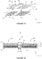
- Figure 1A is a schematic structural diagram of a first electrode 100, a separator film 118, and a second electrode 110 for making a flexible (also "bendable,” or “curved") battery, in accordance with some embodiments.
- the first electrode 100 includes a plurality of segments, including a first coated segment 105 and a second coated segment 109 interconnected by an uncoated segment 106 between the first and second segments.
- the first coated segment 105, the uncoated segment 106, and the second coated segment 109 are sequentially disposed along X direction.
- the first coated segment 105 and the second coated segment 109 of the first electrode 100 are formed by coating first active material 122 ( Figure 1B ) on one surface (i.e., the surface facing the second electrode 110) or both surfaces of a first current collector 104.
- the uncoated segment 106 corresponds to an uncoated (e.g., bare) portion of the first current collector 104.
- the first electrode 100 further includes a tab 107 (also referred to as "a terminal" or "a contact”).
- the tab 107 is attached to the uncoated segment 106.
- the tab 107 is a part of the current collector 104 that is connected to the uncoated segment 106 and preserved from a metal sheet when cutting the first current collector 104 out from the metal sheet.
- the second electrode 110 includes a plurality of segments, including a first coated segment 115 and a second coated segment 119 interconnected by an uncoated segment 116 between the first and second segments.
- the first coated segment 115, the uncoated segment 116, and the second coated segment 119 are sequentially disposed along X direction.
- the first coated segment 115 and the second coated segment 119 of the second electrode 110 are formed by coating second active material 124 ( Figure 1B ) on one surface (i.e., the surface facing the first electrode 100) or both surfaces of a second current collector 114.
- the uncoated segment 116 corresponds to an uncoated (e.g., bare) portion of the second current collector 114.
- the second electrode 110 further includes a tab 117.
- the tab 117 is attached to the uncoated segment 116.
- the tab 117 is a part of the current collector 114 that is connected to the uncoated segment 116 and preserved from a metal sheet when cutting the second current collector 114 out from the metal sheet.
- the tab 107 and the tab 117 are disposed on opposite sides of the battery 140 and extend towards opposite directions as illustrated in Figures 1A-1C . In some embodiments, the tabs do not overlap along the thickness dimension.
- the first electrode 100 as discussed in Figures 1A-1B is a cathode
- the second electrode 110 is an anode of the battery 140.
- the first electrode 100 is an anode
- the first electrode 110 is a cathode of the battery 140.
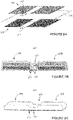
- Figures 1B-1C are cross-sectional view and perspective view of the battery 140 respectively, in accordance with some embodiments.
- the battery 140 includes a first cell 102 and a second cell 103 interconnected via a connection 126.
- the connection 126 is disposed between the first cell 102 and the second cell 103 along X direction and is electrically coupled between the first cell 102 and the second cell 103.
- electrolyte (not shown) is disposed between the two electrodes.
- a packaging film 130 is used to seal and package the battery 140.
- the second cell 103 includes a third electrode and a fourth electrode.
- the third electrode includes a third current collector and a third active material coated on a surface of the third current collector.
- the fourth electrode is opposite to the third electrode, and includes a fourth current collector and a fourth active material coated on a surface of the fourth current collector.
- the first current collector 104, the first connection current collector, and the third current collector are electrically connected.
- the third electrode may adopt a same configuration with the first electrode 100
- the fourth electrode may adopt a same configuration with the second electrode 110, as illustrated in Figure 1B .
- the battery 140 is formed by sequentially stacking the first electrode 100, the separator 118, and the second electrode 110 along Y direction as illustrated in Figure 1A .
- the first cell 102 includes the first segment 105 of the first electrode 100, the first segment 115 of the second electrode 110, and a portion of the separator 118 and electrolyte disposed between the first and second electrodes.
- the second cell 103 includes the second segment 109 of the first electrode 100, the second segment 119 of the second electrode 110, and a portion of the separator 118 and electrolyte disposed between the first and second electrodes.
- connection 126 includes the uncoated segment 106 of the first electrode 100, the uncoated segment 116 of the second electrode 110, and a portion of the separator 118 disposed in-between.
- the uncoated segments 106 and 116 at the connection 126 are also referred to as "connection current collectors.”
- connection 126 may or may not include electrolyte.
- the connection 126 is thinner than the first cell 102 or the second cell 103.
- the uncoated anode current collector selected from the uncoated segments 106 and 116 of the first and second electrodes respectively has a smaller area than the uncoated cathode current collectors between the uncoated segments 106 and 116.
- the coated anode segment e.g., selected from the coated segments 105 and 115
- the coated cathode segment e.g., between the coated segments 105 and 115
- the total uncoated area on an electrode e.g., including one or more uncoated segments such as uncoated segment 106, takes up less than 50% area of the entire current collector of the electrode.
- the connection 126 includes one or two uncoated current collectors (e.g., cathode current collector and/or anode current collector). In some other embodiments, the connection 126 includes one or two current collectors (e.g., cathode current collector and/or anode current collector) that are coated with active materials on only one surface of each current collector. In yet some other embodiments, the connection 126 includes one or two current collectors (e.g., cathode current collector and/or anode current collector) that are coated with active materials on both surfaces of each current collector.
- a length 1 of the connection 126 (e.g., the length of the uncoated or coated current collector in its original straightened and flattened state without folds, creases, or deformation to the material as shown in Figure 1A ) along the X direction is longer than a distance d between the first cell 102 and the second cell 103 in the packaged battery 140 as illustrated in Figure 1B (e.g., without bending, stretching, or twisting the battery).
- the uncoated current collectors 106 and 116, the separator 118, and the packaging film 130 at the connection area 126 has folded structures that are configured to accommodate a dimensional change of the battery 140.
- the folded structures of the connection 126 can bend, stretch, or twist accordingly to accommodate the shape and/or volume change without bringing mechanical or electrical failures, or plastic deformation to the materials of the battery 140.
- the cathode current collector comprises an aluminium (Al) sheet
- the anode current collector comprises a copper (Cu) sheet.
- each of the cathode current collector and the anode current collector is bendable and has a thickness in a range from about 100 nm to about 5000 ⁇ m.
- the materials and the design of the cathode current collector and the anode current collector provide sufficient strength to withstand an applied load to bend the battery without causing failure or plastic deformation to the materials.
- the coated current collectors within the packaged battery can bend and hold a certain curvature to accommodate the shape of a wearable electronic device.
- the anode active material includes one material or a mixture of two or more materials selected from carbon-based anode (e.g., graphite, graphene, carbon nanotubes, carbon nanowires, etc.), tin(Sn)-based anode (e.g., SnO 2 , Sn-based composites, Sn-based compounds, Sn-based alloys), silicon(Si)-based anode (e.g., SiO 2 , Si-based composites, Si-based compounds), titanium oxide (TiO 2 ), Ti-based alloys, lithium metal (Li), and iron oxide (Fe 2 O 3 , Fe 3 O 4 , etc.).
- carbon-based anode e.g., graphite, graphene, carbon nanotubes, carbon nanowires, etc.
- tin(Sn)-based anode e.g., SnO 2 , Sn-based composites, Sn-based compounds, Sn-based alloys
- the compatibilities of working voltages and chemistry between the cathode and the anode may also be considered when selecting the cathode active material and the anode active material for a lithium ion battery.
- the cathode active material and the anode active material have particle sizes in a range from a few nanometers (nm) to a few hundreds of micrometres ( ⁇ m).
- the cathode and anode active materials have various particle shapes, such as nanoparticles, nanotubes, nanopowders, nanoballs, nanoflakes, nanowires, etc.
- the active material is mixed with additives and binders to form a paste which is then coated on the corresponding current collector to form the corresponding electrode.
- the active material can be deposited onto the corresponding current collector using any suitable method, such as chemical vapour deposition (CVD), physical vapour deposition (PVD), pulsed laser deposition (PLD), magnetron sputtering deposition, electrochemical depo, epitaxial growth, spin coating method, etc.
- CVD chemical vapour deposition
- PVD physical vapour deposition
- PLD pulsed laser deposition
- magnetron sputtering deposition electrochemical depo
- epitaxial growth spin coating method, etc.
- the separator 118 is made of one or more materials selected from polyethylene, polypropylene, polyethylene terephthalate, polyimide, and aramid.
- polyethylene for the separator can be high-density polyethylene, low-density polyethylene, or polyethylene with ultra-high molecular weight.
- Polyethylene separator and polypropylene separator can effectively prevent short-circuit between the cathode current collector and the anode current collector and thus improve stability and cycle performance of the battery.
- one or both surfaces of the separator is porous, and the porous layer includes inorganic particles and binders.
- the inorganic particles include one or more inorganic compounds selected from aluminum oxide (Al 2 O 3 ), silicon oxide (SiO 2 ), magnesium oxide (MgO), titanium oxide (TiO2), hafnium dioxide (HfO 2 ), tin oxide (SnO 2 ), cerium oxide (CeO 2 ), nickel oxide (NiO), zinc oxide (ZnO), calcium oxide (CaO), zirconium oxide (ZrO 2 ), yttrium oxide (Y 2 O 3 ), silicon carbide (SiC), boehmite, aluminum hydroxide, magnesium hydroxide, calcium hydroxide, and barium sulfate.
- aluminum oxide Al 2 O 3
- silicon oxide SiO 2
- magnesium oxide MgO
- titanium oxide TiO2
- hafnium dioxide HfO 2
- tin oxide SnO 2
- cerium oxide CeO 2
- NiO nickel oxide
- ZnO zinc oxide
- CaO calcium oxide
- ZrO 2 zirconium oxide
- the binders include one or more types of materials selected from polyvinylidene fluoride, vinylidene fluoride-hexafluoropropylene copolymer, polyamide, polyacrylonitrile, polyacrylate, polyacrylic acid, carboxymethylcellulose sodium, polyvinyl pyrrolidone, polyethylene, polymethylmethacrylate, polytetrafluoroethylene, and polyhexafluoropropylene.
- the porous surface can improve thermal resistance and oxidation resistance of the separator.
- the porous surface can also have an improved electrolyte infiltration effect to provide a better contact between the separator and the cathode and anode,
- the battery 140 includes an electrolyte (not shown) disposed between the cathode and the anode.
- the battery 140 can use a liquid electrolyte, a gel electrolyte, or a solid electrolyte.
- the liquid electrolyte can be one or more lithium-based salts selected from LiPF 6 , LiBF 4 , LiAsF 6 , LiClO 4 LiB(C 6 H 5 ) 4 , LiCH 3 SO 3 , LiCF 3 SO 3 , LiN(SO 2 CF 3 ) 2 . LiC(SO 2 CF 3 ) 3 , LiSiF 6 . LiBO and LIODFB dissolved in a nonaqueous solvent.
- the nonaqueous solvent may include a carbonate ester compound, a carboxylic acid compound, an ether compound, other suitable organic solvent, or a combination thereof.
- the carbonate ester compound may be a chain carbonate compound, a cyclic carbonate compound, a fluorocarbonate compound, or a combination thereof.
- chain carbonate compounds include diethyl carbonate (DEC), dimethyl carbonate (DMC), dipropyl carbonate (DPC), methylpropyl carbonate (MPC), ethylene carbonate (EPC), carbonic acid ethyl acetate (MEC), and combinations thereof.
- Examples of cyclic carbonate compounds include ethylene carbonate (EC), propylene carbonate (PC), butylene carbonate (BC), vinyl ethylene carbonate (VEC), and combinations thereof.
- fluorocarbonate compounds include fluoroethylene carbonate (FEC), 1,2-difluoroethylene carbonate, 1,1-difluoroethylene carbonate, and 1,1,2-tricarboxylic acid, fluoroethylene, 1,1,2,2-tetrafluoroethylene carbonate, 1-fluoro-2-methylethyl carbonate, 1-fluoro-1-methyl-ethylene carbonate, carbonic acid 1,2-Difluoro-1-methylethylene, 1,1,2-trifluoro-2-methylethyl carbonate, trifluoromethyl ethylene carbonate, and combinations thereof.
- carboxylic acid ester compounds include methyl acetate, ethyl acetate, n-propyl acetate, tert-butyl acetate, methyl propionate, ethyl propionate, ⁇ -butyrolactone, terpene lactone, valerolactone, DL-mevalonic acid lactone, caprolactone, methyl formate, and combinations thereof.
- ether compounds include dibutyl ether, tetraethylene glycol dimethyl ether, diethylene glycol dimethyl ether, 1,2-dimethoxyethane, 1,2-diethoxyethane, and ethoxymethoxyethane, 2-methyltetrahydrofuran, tetrahydrofuran and combinations thereof.
- organic solvents examples include dimethyl sulfoxide, 1,2-dioxolane, sulfolane, methyl sulfolane, 1,3-dimethyl-2-imidazolidinone, N-methyl-2-pyrrolidone, Formamide, dimethylformamide, acetonitrile, trimethyl phosphate, triethyl phosphate, trioctyl phosphate, phosphate esters, and combinations thereof.
- the packaging material 130 includes three layers.
- the inner layer (closest to the electrodes) is made of a polymer material such as polypropylene.
- the outer layer may be made of a polymer material such as nylon.
- the middle layer disposed between the inner layer and the outer layer is a metal layer, such as an aluminum (Al) or a stainless steel sheet.
- Figure 1D illustrates an exemplary method of shaping a curved battery (e.g., a flexible battery) to accommodate a shape of a wearable device.
- Figure 1E illustrates a curved battery 170 formed using the method of Figure 1D .
- Figure 1F is a schematic diagram illustrating a wearable device 180 that contains the curved battery 170, in accordance with some embodiments.
- the curved battery is formed by a die forging process (e.g., or a metal pressing) as illustrated in Figure 1D .
- one or more dies are used to shape the battery.
- the battery 140 may be heated to a certain temperature during the bending process (wherein the temperature does not cause electrochemical and/or material failure of the battery 140).
- the packaged battery 140 ( Figures 1B-1C ) is placed between a concaved shaped die 152 (e.g., an arc) and a convex shaped die 150, and a predetermined pressure or force is applied to bend the battery to have a certain curvature.
- a concaved shaped die 152 e.g., an arc
- a convex shaped die 150 e.g., a predetermined pressure or force
- connection 126 is bended, and the first and second cells 102 and 103 are also bended to have a certain curvature.
- the curvature is predetermined in accordance with the shape of the wearable device (e.g., the wearable device 180, Figure 1F ), which is powered by the curved battery 170.
- the connection 126 is flexible (e.g., bendable) during use of the wearable device.
- the connection 126 is located at the bendable part 182 of the wearable device 180, such that the connection 126 can bend to a certain degree to make it more convenient for the user to put on and take off the wearable device 180 through bending the part 182.
- the wearable device 180 includes, but is not limited to, a head-mounted display, a piece of clothing, a smart watch, a smart ring, a smart band, a pair of glasses/goggles, etc.
- the wearable device 180 can be used for a gaming device, a medical device, a personal fitness tracker, or a sports tracker, etc.
- Figure 2A is a schematic diagram of a first electrode 200, a separator 218, and a second electrode 210 for making a flexible battery, in accordance with some embodiments.
- the first electrode 200, the separator 218, and the second electrode 210 are substantially similar to the first electrode 100, the separator 118, and the second electrode 110 respectively, as discussed with reference to Figure 1A .
- a first tab 207 on the first electrode 200 and a second tab 217 on the second electrode 210 are disposed on the same side of the battery 240 ( Figures 2B-2C ) and extend towards the same direction as illustrated in Figures 2A-2C .
- Figures 2B and 2C includes a cross-sectional view and a perspective view of a flexible battery 240, in accordance with some embodiments.
- the flexible battery 240 includes a first cell 202 and a second cell 203 interconnected via a connection 226.
- the first cell 202, the connection 226, and the second cell 203 are substantially similar to the first cell 102, the connection 126, and the second cell 103 of the flexible battery 140 as discussed with reference to Figures 1B-1C .
- the tabs 207 and 217 are disposed on the same side of the battery 240 and extend towards the same direction as illustrated in Figures 2A-2C .
- Figure 3A is a schematic diagram of a first electrode 300, a separator 318, and a second electrode 310 for making a flexible battery 340, in accordance with some embodiments.
- the first electrode 300, the separator 318, and the second electrode 310 are substantially similar to the first electrode 100, the separator 118, and the second electrode 110 respectively, as discussed with reference to Figure 1A .
- a first tab 307 on the first electrode 300 and a second tab 317 on the second electrode 310 are disposed on opposite ends (along X direction) of the battery 340 ( Figure 3B ) and extend towards opposite directions as illustrated in Figures 3A-3B .
- Figure 3B includes a cross-sectional view of the flexible battery 340, in accordance with some embodiments.
- the flexible battery 340 includes a first cell 302 and a second cell 303 interconnected via a connection 326.
- the first cell 302, the connection 326, and the second cell 303 are substantially similar to the first cell 102, the connection 126, and the second cell 103 of the flexible battery 140 as discussed with reference to Figures 1B-1C .
- the tabs 307 and 317 are disposed on opposite ends (along X direction) of the battery 340 and extend towards opposite directions as illustrated in Figures 3A-3B .
- Figure 4A is a schematic diagram a first electrode 400, a separator 418, and a second electrode 410 for making a flexible battery.
- the first electrode 400 e.g., cathode or anode
- the second electrode 410 e.g., anode or cathode opposite to the first electrode 400
- the first electrode 400 includes more than one uncoated segment (e.g., uncoated current collector) that is similar to the uncoated segment 106 ( Figure 1A ).
- the second electrode 410 includes more than one uncoated segment that is similar to the uncoated segment 116 ( Figure 1A ).
- Figure 4B is a schematic diagram of a flexible battery 440 including multiple flexible connections 426, each of which respectively disposed between adjacent cells 402, in accordance with some embodiments.
- the flexible battery 440 includes more than two cells 402 interconnected via flexible connections 426.
- the cell 402 and the connection 426 are substantially similar to the cell 102 and the connection 126 of the flexible battery 140 as discussed with reference to Figures 1B-1C .
- the flexible battery 440 is also sealed and packaged.
- the increased number of flexible connections 426 within the flexible battery 440 can substantially improve the flexibility of the battery 440.
- Figure 4C is a schematic diagram of a curved battery 470, in accordance with some embodiments.
- the curved battery 470 may include a first curved cell 402, a second curved cell 402 and a connection 426, the second curved cell is interconnected with the first curved cell 402, and the connection 426 is electrically coupled between the first curved cell and the second curved cell, wherein the connection 426 has a folded structure that is bendable.
- the curved battery 470 is formed using the die forging process as shown in Figure 1D .
- the packaged battery 440 is placed between a concaved shaped die and a convex shaped die as shown in Figure 1D , and a predetermined pressure or force is applied to bend the battery to have a certain curvature.
- the multiple flexible connections 426 of the curved battery 470 can further bend to certain degrees as needed by the user when using the wearable device.
- the tabs 407 and 417 are similar to the tabs 107 and 117 respectively ( Figure 1A ), and they are disposed on opposite sides of the corresponding electrode and pointing to opposite directions. In some other embodiments, the tabs 408 and 418 are disposed on the same side of the battery 440 ( Figure 4B ) and extend towards the same direction as illustrated in Figure 4B .
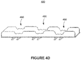
- Figure 4D is a schematic diagram of a flexible battery 480 including a plurality of flexible connections 486 and a plurality of pairs of tabs, in accordance with some embodiments.
- the plurality pairs of the tabs can be disposed on the same side of the electrode or opposite sides of the electrode.
- the plurality of pairs of tabs can improve the power density of the battery 480 such that the battery 480 can have high performance when discharged at a fast discharging rate.
- FIGS 5A-5B are schematic diagrams of customized electrodes for flexible batteries, in accordance with some embodiments.
- the electrode (e.g., the current collector) 500 has a customized shape that fits in the wearable device.
- the electrode 500 may be in rectangular shape, square shape, triangular shape, other regular polygons, or asymmetrical polygons.
- the electrode 500 may have a plurality of coated segments that are connected via multiple flexible connections respectively to improve the flexibility of the electrode 500.
- Figure 5B is a schematic diagram of a first electrode 522, a separator 530, and a second electrode 524 for making a flexible battery, in accordance with some embodiments.
- the first electrode 522, the separator 530, and the second electrode 524 are made of substantially similar materials as the first electrode 100, the separator 118, and the second electrode 110 respectively, as discussed with reference to Figure 1A .
- the connection 526 of the first electrode 522 and the connection 528 of the second electrode 524 may each includes a porous structure to further improve the flexibility of the respective electrodes.
- the tabs may be disposed on the same side or opposite sides of the electrodes.
- connection may comprise one or more strips (not shown) connecting a first cell 532 with a second cell 534.
- the one or more strips are electrical conducting.
- the one or more strips are parallel to each other along X direction.
- the one or more strips may be portions of the uncoated current collectors (e.g., cathode current collector and/or anode current collector). The number, width, and length of the one or more strips may be selected in accordance with a degree of flexibility (e.g., a range of degrees of bending) required when using the wearable device.
- FIG. 6A is a schematic diagram illustrating a flexible battery 600 including a plurality of cells 602 that are interconnected by flexible connections 604, in accordance with some embodiments.
- each cell 602 comprises a stacking cell 610, such as a bi-cell stacking cell or a z-shaped stacking cell.
- each cell 602 comprises a jelly-roll cell 620.
- each electrode within a cell may include a tab.
- a stacking cell 610 or a rolling cell 620 may include a plurality of pairs of tabs as shown in Figure 6A .
- the flexible battery 600 with a stacking or rolling structure that have a plurality of tabs can provide high energy density and high power density to power the wearable device.
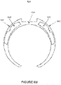
- FIG. 6B is a schematic diagram illustrating a wearable device 630 including a plurality of flexible batteries 640.
- each flexible battery 640 is substantially similar to the flexible battery 140 as discussed with reference to Figure 1C .
- one or more flexible batteries 640 are distributed at one or more curved portions 632 of the wearable device 630.
- a flexible battery includes a plurality of customized (e.g., curved) cells that are interconnected by one or more flexible connections.
- a flexible connection includes a folded structure that can bend, stretch, or twist without bringing mechanical or electrical failures, or plastic deformation to the materials of the flexible battery.
- Such flexible battery can be used to power a wearable and bendable device.
- first, second, etc. may be used herein to describe various elements, these elements should not be limited by these terms. These terms are only used to distinguish one element from another.
- a first electrode could be termed a second electrode, and, similarly, a second electrode could be termed a first electrode, without departing from the scope of the embodiments.
- the first electrode and the second electrode are both electrodes, but they are not the same electrode.
Landscapes
- Chemical & Material Sciences (AREA)
- Chemical Kinetics & Catalysis (AREA)
- Electrochemistry (AREA)
- General Chemical & Material Sciences (AREA)
- Engineering & Computer Science (AREA)
- Manufacturing & Machinery (AREA)
- Life Sciences & Earth Sciences (AREA)
- Biophysics (AREA)
- Computer Hardware Design (AREA)
- Materials Engineering (AREA)
- Connection Of Batteries Or Terminals (AREA)
- Secondary Cells (AREA)
Claims (15)
- Batterie (140), umfassend:eine erste Zelle (102);eine zweite Zelle (103), die mit der ersten Zelle (102) verbunden ist; undeine Verbindung (126), die elektrisch zwischen der ersten Zelle (102) und der zweiten Zelle (103) gekoppelt ist,dadurch gekennzeichnet, dass sich die Verbindung (126) von der ersten Zelle (102) zu der zweiten Zelle (103) entlang einer ersten Richtung erstreckt und eine Länge der Verbindung (126) entlang der ersten Richtung größer als ein Abstand zwischen der ersten Zelle (102) und der zweiten Zelle (103) ist.
- Batterie (140) nach Anspruch 1, wobei die Verbindung (126) eine gefaltete Struktur umfasst, die konfiguriert ist, einer Dimensionsänderung entgegenzukommen.
- Batterie (140) nach Anspruch 1 oder 2, wobei die Verbindung (126) einen Verbindungsstromkollektor umfasst.
- Batterie (140) nach Anspruch 1 oder 2, wobei die Verbindung (126) einen ersten Verbindungsstromkollektor (106), einen Separator (108) und einen zweiten Verbindungsstromkollektor (116) umfasst, die entlang einer zweiten Richtung senkrecht zu der ersten Richtung aufeinander gestapelt sind.
- Batterie (140) nach Anspruch 4, wobei:die erste Zelle (102) umfasst:eine erste Elektrode (100), die einen ersten Stromkollektor (104) und ein erstes aktives Material (122) umfasst, das auf eine Oberfläche des ersten Stromkollektors (104) aufgetragen ist; undeine zweite Elektrode (110) gegenüber der ersten Elektrode (100), die einen zweiten Stromkollektor (114) und ein zweites aktives Material (124) umfasst, das auf eine Oberfläche des zweiten Stromkollektors (114) aufgetragen ist; unddie zweite Zelle (103) umfasst:eine dritte Elektrode, die einen dritten Stromkollektor und ein drittes aktives Material umfasst, das auf eine Oberfläche des dritten Stromkollektors aufgetragen ist; undeine vierte Elektrode gegenüber der dritten Elektrode, die einen vierten Stromkollektor und ein viertes aktives Material umfasst, das auf eine Oberfläche des vierten Stromkollektors aufgetragen ist.
- Batterie (140) nach Anspruch 5, wobei der erste Stromkollektor (104), der erste Verbindungsstromkollektor und der dritte Stromkollektor elektrisch verbunden sind.
- Batterie (140) nach einem der Ansprüche 1 bis 6, wobei die Verbindung (126) eine poröse Struktur umfasst.
- Batterie (140) nach einem der Ansprüche 1 bis 7, wobei die Verbindung (126) einen oder mehrere Streifen umfasst, die sich von der ersten Zelle (102) zu der zweiten Zelle (103) erstrecken, wobei der eine oder die mehreren Streifen entlang der ersten Richtung parallel zueinander sind.
- Batterie (140) nach einem der Ansprüche 1 bis 8, wobei die Verbindung (126) eine Verbindungsverpackungsfolie umfasst, die größer als der Abstand zwischen der ersten Zelle (102) und der zweiten Zelle (103) ist.
- Batterie (140) nach einem der Ansprüche 1 bis 9, wobei mindestens eine der ersten Zelle (102) und der zweiten Zelle (103) eine Bogenstruktur aufweist.
- Batterie (140) nach einem der Ansprüche 1 bis 10, wobei die Verbindung (126) eine Lasche (207, 217) umfasst.
- Batterie (140) nach einem der Ansprüche 1 bis 11, wobei die Verbindung (126) eine konkave Struktur umfasst, die dünner als die erste Zelle (102) und die zweite Zelle (103) ist.
- Batterie (140) nach einem der Ansprüche 1 bis 12, wobei die erste Zelle (102) eine Stapelzelle (610) umfasst.
- Batterie (140) nach einem der Ansprüche 1 bis 12, wobei die erste Zelle (102) eine Jelly-Roll-Zelle (620) umfasst.
- Tragbare Vorrichtung, umfassend:eine Batterie (140) nach einem der Ansprüche 1 bis 14; undeinen biegbaren Teil (182), wobei sich die Verbindung (126) der Batterie (140) an dem biegbaren Teil (182) befindet.
Applications Claiming Priority (1)
| Application Number | Priority Date | Filing Date | Title |
|---|---|---|---|
| CN201810885472.8A CN110808418B (zh) | 2018-08-06 | 2018-08-06 | 用于可穿戴设备的柔性电池 |
Publications (2)
| Publication Number | Publication Date |
|---|---|
| EP3608996A1 EP3608996A1 (de) | 2020-02-12 |
| EP3608996B1 true EP3608996B1 (de) | 2023-01-25 |
Family
ID=67544116
Family Applications (1)
| Application Number | Title | Priority Date | Filing Date |
|---|---|---|---|
| EP19190006.7A Active EP3608996B1 (de) | 2018-08-06 | 2019-08-05 | Flexible batterien für wearable-vorrichtungen |
Country Status (3)
| Country | Link |
|---|---|
| US (1) | US10998601B2 (de) |
| EP (1) | EP3608996B1 (de) |
| CN (1) | CN110808418B (de) |
Families Citing this family (5)
| Publication number | Priority date | Publication date | Assignee | Title |
|---|---|---|---|---|
| US11961972B1 (en) * | 2019-06-25 | 2024-04-16 | Ccl Label, Inc. | Flexible multi-battery assemblies, flexible electrochemical cells forming such assemblies, and methods of fabricating thereof |
| KR102781215B1 (ko) * | 2020-06-10 | 2025-03-14 | 주식회사 엘지에너지솔루션 | 폴딩부를 포함하는 전극 제조방법 및 폴딩부를 포함하는 전극 시트 |
| KR20220079323A (ko) * | 2020-12-04 | 2022-06-13 | 삼성전자주식회사 | 플렉서블 전극 조립체 및 이를 포함하는 배터리 |
| CN114695898A (zh) * | 2020-12-30 | 2022-07-01 | 深圳信达新能源科技有限公司 | 一种带通孔的极片及电池 |
| CN113314762A (zh) * | 2021-04-07 | 2021-08-27 | 湖州柔驰新能科技有限公司 | 一种多功能柔性电池及其制备方法 |
Family Cites Families (4)
| Publication number | Priority date | Publication date | Assignee | Title |
|---|---|---|---|---|
| CN102792488B (zh) * | 2010-03-15 | 2015-11-25 | 丰田自动车株式会社 | 电池及其制造方法 |
| CN104752651A (zh) * | 2014-01-01 | 2015-07-01 | 许振宇 | 一种可以弯曲和折叠的电池结构 |
| US20160301044A1 (en) * | 2015-04-10 | 2016-10-13 | Zhen Huang | Flexible Battery System for Portable Device |
| CN108027589B (zh) * | 2015-07-31 | 2020-09-01 | 宋永僖 | 在带上安装有柔性半导体封装的可穿戴智能设备 |
-
2018
- 2018-08-06 CN CN201810885472.8A patent/CN110808418B/zh active Active
- 2018-09-07 US US16/125,378 patent/US10998601B2/en active Active
-
2019
- 2019-08-05 EP EP19190006.7A patent/EP3608996B1/de active Active
Also Published As
| Publication number | Publication date |
|---|---|
| EP3608996A1 (de) | 2020-02-12 |
| US20200044222A1 (en) | 2020-02-06 |
| CN110808418B (zh) | 2022-02-22 |
| CN110808418A (zh) | 2020-02-18 |
| US10998601B2 (en) | 2021-05-04 |
Similar Documents
| Publication | Publication Date | Title |
|---|---|---|
| EP3608996B1 (de) | Flexible batterien für wearable-vorrichtungen | |
| US11626581B2 (en) | Current collector, comprising a slit and secondary battery comprising thereof | |
| EP3200263B1 (de) | Sekundärbatterie und verfahren zu deren herstellung | |
| KR100933427B1 (ko) | 교차분리막으로 이루어진 전기화학소자 | |
| KR102708552B1 (ko) | 이차 전지 | |
| JP6441125B2 (ja) | 非水電解質電池及び電池パック | |
| EP3080857B1 (de) | Batterie und zusammengesetzte batterie | |
| US11158844B2 (en) | Shared electrode segments between a step cell and a main cell of a stepped battery | |
| JP6246901B2 (ja) | 非水電解質電池及び電池パック | |
| US12322795B2 (en) | Lithium ion secondary battery | |
| JP2008192594A (ja) | 非水電解質二次電池用負極とその製造方法およびそれを用いた非水電解質二次電池 | |
| CN101346836B (zh) | 非水电解质二次电池用负极及其制造方法以及采用该负极的非水电解质二次电池 | |
| US20150340726A1 (en) | Energy storage device | |
| WO2012114904A1 (ja) | 非水電解質二次電池 | |
| WO2017104028A1 (ja) | 非水電解質電池及び電池パック | |
| CN111164817A (zh) | 锂离子二次电池 | |
| JP2018174110A (ja) | 集電体、及びリチウムイオン二次電池 | |
| JP5150095B2 (ja) | 非水電解質電池 | |
| CN112335091B (zh) | 锂离子二次电池 | |
| CN112335092B (zh) | 锂离子二次电池 | |
| CN113169298B (zh) | 电极、电池及电池包 | |
| WO2018155035A1 (ja) | リチウムイオン電池 | |
| JP2024043351A (ja) | 電極、電池、電池パック、車両、及び定置用電源 | |
| JP2007280749A (ja) | 非水電解質二次電池 |
Legal Events
| Date | Code | Title | Description |
|---|---|---|---|
| PUAI | Public reference made under article 153(3) epc to a published international application that has entered the european phase |
Free format text: ORIGINAL CODE: 0009012 |
|
| STAA | Information on the status of an ep patent application or granted ep patent |
Free format text: STATUS: THE APPLICATION HAS BEEN PUBLISHED |
|
| AK | Designated contracting states |
Kind code of ref document: A1 Designated state(s): AL AT BE BG CH CY CZ DE DK EE ES FI FR GB GR HR HU IE IS IT LI LT LU LV MC MK MT NL NO PL PT RO RS SE SI SK SM TR |
|
| AX | Request for extension of the european patent |
Extension state: BA ME |
|
| STAA | Information on the status of an ep patent application or granted ep patent |
Free format text: STATUS: REQUEST FOR EXAMINATION WAS MADE |
|
| 17P | Request for examination filed |
Effective date: 20200812 |
|
| RBV | Designated contracting states (corrected) |
Designated state(s): AL AT BE BG CH CY CZ DE DK EE ES FI FR GB GR HR HU IE IS IT LI LT LU LV MC MK MT NL NO PL PT RO RS SE SI SK SM TR |
|
| REG | Reference to a national code |
Ref country code: DE Ref legal event code: R079 Ref document number: 602019024713 Country of ref document: DE Free format text: PREVIOUS MAIN CLASS: H01M0002220000 Ipc: H01M0050207000 |
|
| RIC1 | Information provided on ipc code assigned before grant |
Ipc: H01M 50/534 20210101ALI20220714BHEP Ipc: H01M 50/528 20210101ALI20220714BHEP Ipc: H01M 50/503 20210101ALI20220714BHEP Ipc: H01M 4/80 20060101ALI20220714BHEP Ipc: H01M 50/247 20210101ALI20220714BHEP Ipc: H01M 50/207 20210101AFI20220714BHEP |
|
| GRAP | Despatch of communication of intention to grant a patent |
Free format text: ORIGINAL CODE: EPIDOSNIGR1 |
|
| STAA | Information on the status of an ep patent application or granted ep patent |
Free format text: STATUS: GRANT OF PATENT IS INTENDED |
|
| INTG | Intention to grant announced |
Effective date: 20220907 |
|
| GRAS | Grant fee paid |
Free format text: ORIGINAL CODE: EPIDOSNIGR3 |
|
| GRAA | (expected) grant |
Free format text: ORIGINAL CODE: 0009210 |
|
| STAA | Information on the status of an ep patent application or granted ep patent |
Free format text: STATUS: THE PATENT HAS BEEN GRANTED |
|
| AK | Designated contracting states |
Kind code of ref document: B1 Designated state(s): AL AT BE BG CH CY CZ DE DK EE ES FI FR GB GR HR HU IE IS IT LI LT LU LV MC MK MT NL NO PL PT RO RS SE SI SK SM TR |
|
| REG | Reference to a national code |
Ref country code: GB Ref legal event code: FG4D |
|
| REG | Reference to a national code |
Ref country code: CH Ref legal event code: EP |
|
| REG | Reference to a national code |
Ref country code: AT Ref legal event code: REF Ref document number: 1546458 Country of ref document: AT Kind code of ref document: T Effective date: 20230215 Ref country code: IE Ref legal event code: FG4D |
|
| REG | Reference to a national code |
Ref country code: DE Ref legal event code: R096 Ref document number: 602019024713 Country of ref document: DE |
|
| REG | Reference to a national code |
Ref country code: NL Ref legal event code: FP |
|
| REG | Reference to a national code |
Ref country code: LT Ref legal event code: MG9D |
|
| REG | Reference to a national code |
Ref country code: AT Ref legal event code: MK05 Ref document number: 1546458 Country of ref document: AT Kind code of ref document: T Effective date: 20230125 |
|
| P01 | Opt-out of the competence of the unified patent court (upc) registered |
Effective date: 20230601 |
|
| PG25 | Lapsed in a contracting state [announced via postgrant information from national office to epo] |
Ref country code: RS Free format text: LAPSE BECAUSE OF FAILURE TO SUBMIT A TRANSLATION OF THE DESCRIPTION OR TO PAY THE FEE WITHIN THE PRESCRIBED TIME-LIMIT Effective date: 20230125 Ref country code: PT Free format text: LAPSE BECAUSE OF FAILURE TO SUBMIT A TRANSLATION OF THE DESCRIPTION OR TO PAY THE FEE WITHIN THE PRESCRIBED TIME-LIMIT Effective date: 20230525 Ref country code: NO Free format text: LAPSE BECAUSE OF FAILURE TO SUBMIT A TRANSLATION OF THE DESCRIPTION OR TO PAY THE FEE WITHIN THE PRESCRIBED TIME-LIMIT Effective date: 20230425 Ref country code: LV Free format text: LAPSE BECAUSE OF FAILURE TO SUBMIT A TRANSLATION OF THE DESCRIPTION OR TO PAY THE FEE WITHIN THE PRESCRIBED TIME-LIMIT Effective date: 20230125 Ref country code: LT Free format text: LAPSE BECAUSE OF FAILURE TO SUBMIT A TRANSLATION OF THE DESCRIPTION OR TO PAY THE FEE WITHIN THE PRESCRIBED TIME-LIMIT Effective date: 20230125 Ref country code: HR Free format text: LAPSE BECAUSE OF FAILURE TO SUBMIT A TRANSLATION OF THE DESCRIPTION OR TO PAY THE FEE WITHIN THE PRESCRIBED TIME-LIMIT Effective date: 20230125 Ref country code: ES Free format text: LAPSE BECAUSE OF FAILURE TO SUBMIT A TRANSLATION OF THE DESCRIPTION OR TO PAY THE FEE WITHIN THE PRESCRIBED TIME-LIMIT Effective date: 20230125 Ref country code: AT Free format text: LAPSE BECAUSE OF FAILURE TO SUBMIT A TRANSLATION OF THE DESCRIPTION OR TO PAY THE FEE WITHIN THE PRESCRIBED TIME-LIMIT Effective date: 20230125 |
|
| PG25 | Lapsed in a contracting state [announced via postgrant information from national office to epo] |
Ref country code: SE Free format text: LAPSE BECAUSE OF FAILURE TO SUBMIT A TRANSLATION OF THE DESCRIPTION OR TO PAY THE FEE WITHIN THE PRESCRIBED TIME-LIMIT Effective date: 20230125 Ref country code: PL Free format text: LAPSE BECAUSE OF FAILURE TO SUBMIT A TRANSLATION OF THE DESCRIPTION OR TO PAY THE FEE WITHIN THE PRESCRIBED TIME-LIMIT Effective date: 20230125 Ref country code: IS Free format text: LAPSE BECAUSE OF FAILURE TO SUBMIT A TRANSLATION OF THE DESCRIPTION OR TO PAY THE FEE WITHIN THE PRESCRIBED TIME-LIMIT Effective date: 20230525 Ref country code: GR Free format text: LAPSE BECAUSE OF FAILURE TO SUBMIT A TRANSLATION OF THE DESCRIPTION OR TO PAY THE FEE WITHIN THE PRESCRIBED TIME-LIMIT Effective date: 20230426 Ref country code: FI Free format text: LAPSE BECAUSE OF FAILURE TO SUBMIT A TRANSLATION OF THE DESCRIPTION OR TO PAY THE FEE WITHIN THE PRESCRIBED TIME-LIMIT Effective date: 20230125 |
|
| REG | Reference to a national code |
Ref country code: DE Ref legal event code: R097 Ref document number: 602019024713 Country of ref document: DE |
|
| PG25 | Lapsed in a contracting state [announced via postgrant information from national office to epo] |
Ref country code: SM Free format text: LAPSE BECAUSE OF FAILURE TO SUBMIT A TRANSLATION OF THE DESCRIPTION OR TO PAY THE FEE WITHIN THE PRESCRIBED TIME-LIMIT Effective date: 20230125 Ref country code: RO Free format text: LAPSE BECAUSE OF FAILURE TO SUBMIT A TRANSLATION OF THE DESCRIPTION OR TO PAY THE FEE WITHIN THE PRESCRIBED TIME-LIMIT Effective date: 20230125 Ref country code: EE Free format text: LAPSE BECAUSE OF FAILURE TO SUBMIT A TRANSLATION OF THE DESCRIPTION OR TO PAY THE FEE WITHIN THE PRESCRIBED TIME-LIMIT Effective date: 20230125 Ref country code: DK Free format text: LAPSE BECAUSE OF FAILURE TO SUBMIT A TRANSLATION OF THE DESCRIPTION OR TO PAY THE FEE WITHIN THE PRESCRIBED TIME-LIMIT Effective date: 20230125 Ref country code: CZ Free format text: LAPSE BECAUSE OF FAILURE TO SUBMIT A TRANSLATION OF THE DESCRIPTION OR TO PAY THE FEE WITHIN THE PRESCRIBED TIME-LIMIT Effective date: 20230125 |
|
| PG25 | Lapsed in a contracting state [announced via postgrant information from national office to epo] |
Ref country code: SK Free format text: LAPSE BECAUSE OF FAILURE TO SUBMIT A TRANSLATION OF THE DESCRIPTION OR TO PAY THE FEE WITHIN THE PRESCRIBED TIME-LIMIT Effective date: 20230125 |
|
| PLBE | No opposition filed within time limit |
Free format text: ORIGINAL CODE: 0009261 |
|
| STAA | Information on the status of an ep patent application or granted ep patent |
Free format text: STATUS: NO OPPOSITION FILED WITHIN TIME LIMIT |
|
| 26N | No opposition filed |
Effective date: 20231026 |
|
| PG25 | Lapsed in a contracting state [announced via postgrant information from national office to epo] |
Ref country code: SI Free format text: LAPSE BECAUSE OF FAILURE TO SUBMIT A TRANSLATION OF THE DESCRIPTION OR TO PAY THE FEE WITHIN THE PRESCRIBED TIME-LIMIT Effective date: 20230125 |
|
| PG25 | Lapsed in a contracting state [announced via postgrant information from national office to epo] |
Ref country code: MC Free format text: LAPSE BECAUSE OF FAILURE TO SUBMIT A TRANSLATION OF THE DESCRIPTION OR TO PAY THE FEE WITHIN THE PRESCRIBED TIME-LIMIT Effective date: 20230125 |
|
| REG | Reference to a national code |
Ref country code: CH Ref legal event code: PL |
|
| PG25 | Lapsed in a contracting state [announced via postgrant information from national office to epo] |
Ref country code: MC Free format text: LAPSE BECAUSE OF FAILURE TO SUBMIT A TRANSLATION OF THE DESCRIPTION OR TO PAY THE FEE WITHIN THE PRESCRIBED TIME-LIMIT Effective date: 20230125 |
|
| PG25 | Lapsed in a contracting state [announced via postgrant information from national office to epo] |
Ref country code: LU Free format text: LAPSE BECAUSE OF NON-PAYMENT OF DUE FEES Effective date: 20230805 |
|
| PG25 | Lapsed in a contracting state [announced via postgrant information from national office to epo] |
Ref country code: LU Free format text: LAPSE BECAUSE OF NON-PAYMENT OF DUE FEES Effective date: 20230805 Ref country code: CH Free format text: LAPSE BECAUSE OF NON-PAYMENT OF DUE FEES Effective date: 20230831 |
|
| REG | Reference to a national code |
Ref country code: BE Ref legal event code: MM Effective date: 20230831 |
|
| REG | Reference to a national code |
Ref country code: IE Ref legal event code: MM4A |
|
| PG25 | Lapsed in a contracting state [announced via postgrant information from national office to epo] |
Ref country code: IT Free format text: LAPSE BECAUSE OF FAILURE TO SUBMIT A TRANSLATION OF THE DESCRIPTION OR TO PAY THE FEE WITHIN THE PRESCRIBED TIME-LIMIT Effective date: 20230125 |
|
| PG25 | Lapsed in a contracting state [announced via postgrant information from national office to epo] |
Ref country code: IE Free format text: LAPSE BECAUSE OF NON-PAYMENT OF DUE FEES Effective date: 20230805 |
|
| PG25 | Lapsed in a contracting state [announced via postgrant information from national office to epo] |
Ref country code: IE Free format text: LAPSE BECAUSE OF NON-PAYMENT OF DUE FEES Effective date: 20230805 |
|
| PG25 | Lapsed in a contracting state [announced via postgrant information from national office to epo] |
Ref country code: BE Free format text: LAPSE BECAUSE OF NON-PAYMENT OF DUE FEES Effective date: 20230831 |
|
| PG25 | Lapsed in a contracting state [announced via postgrant information from national office to epo] |
Ref country code: BG Free format text: LAPSE BECAUSE OF FAILURE TO SUBMIT A TRANSLATION OF THE DESCRIPTION OR TO PAY THE FEE WITHIN THE PRESCRIBED TIME-LIMIT Effective date: 20230125 |
|
| PG25 | Lapsed in a contracting state [announced via postgrant information from national office to epo] |
Ref country code: BG Free format text: LAPSE BECAUSE OF FAILURE TO SUBMIT A TRANSLATION OF THE DESCRIPTION OR TO PAY THE FEE WITHIN THE PRESCRIBED TIME-LIMIT Effective date: 20230125 |
|
| PG25 | Lapsed in a contracting state [announced via postgrant information from national office to epo] |
Ref country code: CY Free format text: LAPSE BECAUSE OF FAILURE TO SUBMIT A TRANSLATION OF THE DESCRIPTION OR TO PAY THE FEE WITHIN THE PRESCRIBED TIME-LIMIT; INVALID AB INITIO Effective date: 20190805 |
|
| PG25 | Lapsed in a contracting state [announced via postgrant information from national office to epo] |
Ref country code: HU Free format text: LAPSE BECAUSE OF FAILURE TO SUBMIT A TRANSLATION OF THE DESCRIPTION OR TO PAY THE FEE WITHIN THE PRESCRIBED TIME-LIMIT; INVALID AB INITIO Effective date: 20190805 |
|
| PGFP | Annual fee paid to national office [announced via postgrant information from national office to epo] |
Ref country code: NL Payment date: 20250724 Year of fee payment: 7 |
|
| PGFP | Annual fee paid to national office [announced via postgrant information from national office to epo] |
Ref country code: DE Payment date: 20250716 Year of fee payment: 7 |
|
| PGFP | Annual fee paid to national office [announced via postgrant information from national office to epo] |
Ref country code: GB Payment date: 20250717 Year of fee payment: 7 |
|
| PGFP | Annual fee paid to national office [announced via postgrant information from national office to epo] |
Ref country code: FR Payment date: 20250721 Year of fee payment: 7 |
|
| PG25 | Lapsed in a contracting state [announced via postgrant information from national office to epo] |
Ref country code: TR Free format text: LAPSE BECAUSE OF FAILURE TO SUBMIT A TRANSLATION OF THE DESCRIPTION OR TO PAY THE FEE WITHIN THE PRESCRIBED TIME-LIMIT Effective date: 20230125 |