EP3608730A1 - Annular rotating bezel system comprising a spring ring provided with at least two lugs - Google Patents
Annular rotating bezel system comprising a spring ring provided with at least two lugs Download PDFInfo
- Publication number
- EP3608730A1 EP3608730A1 EP18187998.2A EP18187998A EP3608730A1 EP 3608730 A1 EP3608730 A1 EP 3608730A1 EP 18187998 A EP18187998 A EP 18187998A EP 3608730 A1 EP3608730 A1 EP 3608730A1
- Authority
- EP
- European Patent Office
- Prior art keywords
- ring
- rotating bezel
- toothed ring
- spring ring
- annular
- Prior art date
- Legal status (The legal status is an assumption and is not a legal conclusion. Google has not performed a legal analysis and makes no representation as to the accuracy of the status listed.)
- Granted
Links
- 239000011324 bead Substances 0.000 claims description 14
- MCMNRKCIXSYSNV-UHFFFAOYSA-N Zirconium dioxide Chemical compound O=[Zr]=O MCMNRKCIXSYSNV-UHFFFAOYSA-N 0.000 claims description 6
- 239000000463 material Substances 0.000 claims description 6
- 230000002093 peripheral effect Effects 0.000 claims description 4
- 239000004696 Poly ether ether ketone Substances 0.000 claims description 3
- 229910000831 Steel Inorganic materials 0.000 claims description 3
- PNEYBMLMFCGWSK-UHFFFAOYSA-N aluminium oxide Inorganic materials [O-2].[O-2].[O-2].[Al+3].[Al+3] PNEYBMLMFCGWSK-UHFFFAOYSA-N 0.000 claims description 3
- 229910001092 metal group alloy Inorganic materials 0.000 claims description 3
- 229920002530 polyetherether ketone Polymers 0.000 claims description 3
- 239000010959 steel Substances 0.000 claims description 3
- 239000012815 thermoplastic material Substances 0.000 claims description 3
- 229910000808 amorphous metal alloy Inorganic materials 0.000 claims description 2
- 229910010293 ceramic material Inorganic materials 0.000 claims description 2
- 238000009826 distribution Methods 0.000 claims description 2
- 230000001419 dependent effect Effects 0.000 description 4
- 239000000919 ceramic Substances 0.000 description 3
- 230000009189 diving Effects 0.000 description 3
- 230000002457 bidirectional effect Effects 0.000 description 2
- 238000005034 decoration Methods 0.000 description 2
- 229910052751 metal Inorganic materials 0.000 description 2
- 239000002184 metal Substances 0.000 description 2
- BASFCYQUMIYNBI-UHFFFAOYSA-N platinum Chemical compound [Pt] BASFCYQUMIYNBI-UHFFFAOYSA-N 0.000 description 2
- 241000282461 Canis lupus Species 0.000 description 1
- 229910052581 Si3N4 Inorganic materials 0.000 description 1
- RTAQQCXQSZGOHL-UHFFFAOYSA-N Titanium Chemical compound [Ti] RTAQQCXQSZGOHL-UHFFFAOYSA-N 0.000 description 1
- 229910045601 alloy Inorganic materials 0.000 description 1
- 239000000956 alloy Substances 0.000 description 1
- 238000005452 bending Methods 0.000 description 1
- 229910052804 chromium Inorganic materials 0.000 description 1
- 229910017052 cobalt Inorganic materials 0.000 description 1
- 239000010941 cobalt Substances 0.000 description 1
- GUTLYIVDDKVIGB-UHFFFAOYSA-N cobalt atom Chemical compound [Co] GUTLYIVDDKVIGB-UHFFFAOYSA-N 0.000 description 1
- 238000005520 cutting process Methods 0.000 description 1
- PCHJSUWPFVWCPO-UHFFFAOYSA-N gold Chemical compound [Au] PCHJSUWPFVWCPO-UHFFFAOYSA-N 0.000 description 1
- 239000010931 gold Substances 0.000 description 1
- 229910052737 gold Inorganic materials 0.000 description 1
- 238000004519 manufacturing process Methods 0.000 description 1
- 229910052750 molybdenum Inorganic materials 0.000 description 1
- 229910052759 nickel Inorganic materials 0.000 description 1
- 239000004033 plastic Substances 0.000 description 1
- 229910052697 platinum Inorganic materials 0.000 description 1
- 238000003825 pressing Methods 0.000 description 1
- HQVNEWCFYHHQES-UHFFFAOYSA-N silicon nitride Chemical compound N12[Si]34N5[Si]62N3[Si]51N64 HQVNEWCFYHHQES-UHFFFAOYSA-N 0.000 description 1
- 239000010935 stainless steel Substances 0.000 description 1
- 229910001220 stainless steel Inorganic materials 0.000 description 1
- 229920002994 synthetic fiber Polymers 0.000 description 1
- 239000010936 titanium Substances 0.000 description 1
- 229910052719 titanium Inorganic materials 0.000 description 1
Images


Classifications
-
- G—PHYSICS
- G04—HOROLOGY
- G04B—MECHANICALLY-DRIVEN CLOCKS OR WATCHES; MECHANICAL PARTS OF CLOCKS OR WATCHES IN GENERAL; TIME PIECES USING THE POSITION OF THE SUN, MOON OR STARS
- G04B19/00—Indicating the time by visual means
- G04B19/28—Adjustable guide marks or pointers for indicating determined points of time
- G04B19/283—Adjustable guide marks or pointers for indicating determined points of time on rotatable rings, i.e. bezel
-
- G—PHYSICS
- G04—HOROLOGY
- G04B—MECHANICALLY-DRIVEN CLOCKS OR WATCHES; MECHANICAL PARTS OF CLOCKS OR WATCHES IN GENERAL; TIME PIECES USING THE POSITION OF THE SUN, MOON OR STARS
- G04B19/00—Indicating the time by visual means
- G04B19/06—Dials
- G04B19/18—Graduations on the crystal or glass, on the bezel, or on the rim
Definitions
- the invention relates to an annular rotating bezel system.
- the invention also relates to a watch case comprising a middle part and the annular rotating bezel system rotatably mounted on the middle part.
- the invention further relates to a watch comprising the watch case.
- the watch is for example a diving watch, without this being limiting in the context of the present invention
- Known annular rotating eyeglass systems include a rotating bezel, a toothed ring, and a spring ring.
- a rotating bezel system is for example described in the patent document EP 2,672,333 A1 .
- the spring ring is angularly secured to the rotating bezel, and the toothed ring is angularly secured to the middle part.
- the toothed ring has several teeth regularly distributed around its outer periphery, in this case 120 teeth in the embodiment given in this document.
- the spring ring extends in a plane in which it is capable of deforming elastically along a radius, and cooperates elastically with the toothed ring.
- three lugs in the form of elastic arms and intended to cooperate with the teeth of the toothed ring are formed in an inner periphery of the spring ring, by cutting the latter.
- the three lugs are evenly distributed around the inner periphery of the spring ring. Therefore, whatever the position of the telescope, the three pins are always in engagement with the teeth of the toothed ring in same time, which leads to 120 stable positions for the rotating bezel.
- the number of positions therefore corresponds to the number of teeth.
- the resolution of the indexing of the position of the rotating bezel is therefore limited by the number of possible positions in total for the latter, in this case 120 positions.
- the object of the invention is therefore to provide an annular rotating bezel system making it possible, with an equal number of teeth for the toothed ring compared to the systems of the prior art, to obtain a greater number of stable positions possible for the rotating bezel, and overcoming the aforementioned drawbacks of the state of the art.
- the invention relates to an annular rotating bezel system which comprises the characteristics mentioned in independent claim 1.
- An advantage of the present invention is to allow, with an equal number of teeth for the toothed ring compared to the systems of the prior art, to obtain a greater number of possible stable positions for the rotating bezel. Indeed, thanks to the configuration according to which the or each angle of offset between two successive lugs has a value distinct from an integer sub-multiple of 360 degrees, a single lug is elastically and radially engaged with the teeth of the ring toothed in each position of the telescope. Number of total possible positions for the telescope is then given by the result of the multiplication between the number of pins on the spring ring, and the number of teeth on the toothed ring. This allows to obtain a greater number of possible stable positions for the rotating bezel.
- the spring ring comprises at least two thinned portions arranged to increase the flexibility of the spring ring in its plane, each lug extending from one of the thinned portions.
- This increases the flexibility of the spring ring in its plane.
- the spring ring works in bending in its plane, allowing the pins which it carries to mesh and to degenerate from the toothed ring according to the rotation of the telescope. This makes it possible to reduce the width necessary for the operation of the spring ring in the system, and therefore to obtain a gain in overall dimensions in width of the assembly.
- the rotating bezel comprises at least one bead extending over an internal lateral face of the bezel, and the spring ring has, on an outer periphery, at least one notch in which the bead of the bezel is engaged. This allows the spring ring to be easily linked in rotation to the rotating bezel, while facilitating the positioning of the spring ring in the bezel.
- the toothed ring has, on an inner periphery, at least one bead intended to be received in a notch provided in a cylindrical outer surface of the middle part. This allows easy angular attachment of the toothed ring to the middle part, while facilitating the positioning of the toothed ring on the middle part and to guide the rotating bezel system for mounting on the middle.
- the teeth of the toothed ring and the lugs of the spring ring each have an asymmetrical shape in the plane defined by the spring ring.
- the spring ring can rotate with respect to the toothed ring in only one predefined direction: clockwise or counterclockwise depending on the shape chosen for the teeth.
- This first embodiment of the invention therefore corresponds to a unidirectional rotating bezel.
- the teeth of the toothed ring and the lugs of the spring ring each have a symmetrical shape in the plane defined by the spring ring.
- the spring ring can rotate relative to the toothed ring in one or the other of the two directions: clockwise or counterclockwise.
- This second embodiment of the invention therefore corresponds to a bidirectional rotating bezel.
- the annular rotating bezel system is formed by an independent module, said module being configured to be clipped onto the middle part.
- This makes it possible to obtain a simple and practical assembly of the rotating bezel system on the middle part, also allowing easy disassembly. This simplifies the manufacturing process of the watch case.
- the clip-on mounting system used forms a free hanging system.
- the invention also relates to a watch case comprising the annular rotating bezel system described above, and which comprises the characteristics mentioned in dependent claim 17.
- the invention also relates to a watch comprising the watch case described above, and which comprises the characteristics mentioned in dependent claim 19.
- the figure 1 shows a watch 1 provided with a watch case 2.
- the watch case 2 typically comprises a middle part 4.
- the watch case 2 also includes an annular rotating bezel system 6 as well as a watch movement which extends in a plan, the watch movement not being shown in the figures for reasons of clarity.
- the annular rotating bezel system 6 is mounted for rotation on the middle part 4.
- the annular rotating bezel system 6 is formed by an independent module.
- the annular rotating bezel system 6 is for example clipped onto the middle part 4.
- the middle part 4 is of annular shape.
- the middle part 4 comprises a cylindrical outer surface 8.
- the cylindrical outer surface 8 is for example provided with a peripheral shoulder defined by a side wall 12a and a base 12b. This peripheral shoulder serves as a housing for the rotating bezel system 6.
- the side wall 12a comprises an annular projection or bead 13 extending over the entire perimeter of the side wall 12a and allowing the rotating bezel system 6 to be hooked the middle 4, by clipping.
- the annular rotating bezel system 6 is based on the base 12b.
- the rotating bezel system 6 is thus mounted on the middle part 4, from above the latter, allowing the system 6 to be blocked in an axial direction perpendicular to the plane of the watch movement, while allowing rotation of the bezel around the middle part 4.
- watch case 2 taken as an example in Figures 1 to 9 , the configuration of the watch case is substantially circular.
- the middle part can be made of metal, typically steel, titanium, gold. , platinum or ceramic typically based on alumina, zirconia or silicon nitride.
- the annular rotating bezel system 6 comprises a rotating bezel 14, a toothed ring 18 and a spring ring 20.
- the system 6 further comprises an annular retaining ring 16.
- the system 6 also comprises a ring decoration 22 forcibly engaged on the rotating bezel 14.
- the decoration ring 22 carries for example graduations, typically diving graduations in the case of a diving watch 1.
- the decor ring 22 is for example made of ceramic.
- the rotating bezel 14 is of annular shape and comprises an upper face 23a visible to the user and a lower face 23b. As illustrated in the figure 1 , the rotating bezel 14 is for example provided on an inner periphery with an annular rim 24. The rim annular 24 cooperates by clipping with the projection 13 of the middle part 4, and forms with the latter a free hooking system.
- the rotating bezel 14 is for example made of metal but could be made of any other material, for example ceramic.
- the annular ring 16 holds the toothed ring 18 and the spring ring 20 in the bezel 14, in an axial direction perpendicular to the plane of the watch movement. This makes it easier to mount the rotating bezel 14 on the middle part 4.
- the annular ring 16 is driven into the rotating bezel 14, securing it to the latter.
- the annular ring 16 is secured to the middle part 4.
- the annular ring 16 rests on the base 12b of the middle part 4, and thus surrounds the cylindrical outer surface 8 of the middle part.
- the annular ring 16 is configured to cooperate with the cylindrical outer surface 8 to allow rotation of the rotating bezel 14 on the middle part 4.
- the annular retaining ring 16 is for example a flat ring.
- the annular retaining ring may comprise a simple annular ring of rectangular section over its entire periphery driven into the bezel 14.
- the toothed ring 18 comprises a toothing 26.
- the toothing 26 is provided with several teeth regularly distributed over a periphery of the toothed ring 18, typically on an outer periphery, over 360 degrees.
- the toothed ring 18 also has, on its inner periphery, at least one bead 34 received in a notch 36 provided in the cylindrical outer surface 8 of the middle part 4.
- the toothed ring 18 comprises three beads 34 distributed over 360 degrees and spaced two by two by 120 degrees.
- the cylindrical outer surface 8 of the middle part 4 comprises three corresponding notches 36.
- This bead system 34 / notches 36 allows easy angular attachment of the toothed ring 18 to the middle part 4, while facilitating the positioning of the toothed ring 18 on the middle part 4.
- This system also makes it possible to guide the rotating bezel system 6 for mounting on the middle part.
- the beads 34 are engaged in the notches 36, making it possible to snap the elements inside the system 6 and clip the system 6 onto the middle part 4.
- the toothed ring 18 is formed from a single piece of material.
- the toothed ring 18 is for example made of a metallic alloy, in particular an alloy based on cobalt (40% Co, 20% Cr, 16% Ni and. 7% Mo) commercially called phynox or steel typically a stainless steel for example 316L.
- the toothed ring 18 can be made of a thermoplastic material, in particular a thermostable semi-crystalline thermoplastic material such as for example polyarylamide (Ixef®), polyetheretherketone (PEEK) or also a ceramic material such as zirconia or alumina.
- the toothed ring 18 is arranged to be inserted in the spring ring 20, that is to say that the toothed ring 18 is dimensioned to be able to be placed in the spring ring 20.
- the toothed ring 18 and the spring ring 20 are concentric and coplanar, and are held between the lower face 23b of the bezel 14 and an upper face of the retaining ring 16.
- the spring ring 20 extends in a plane in which it is capable of deforming elastically along a radius.
- the spring ring 20 cooperates elastically with the toothed ring 18.
- the spring ring 20 comprises at least two lugs 40, each lug 40 being configured to be elastically and radially engaged with the teeth 26 of the ring toothed 18 in at least one position of the bezel 14.
- the spring ring 20 comprises three lugs 40.
- the lugs 40 are offset from one another by an offset angle ⁇ a , ⁇ b , ⁇ c .
- Each offset angle ⁇ a , ⁇ b , ⁇ c between two successive lugs 40 has a value distinct from an integer sub-multiple of 360 degrees, as will be detailed below.
- a single lug 40 is elastically and radially engaged with the toothing 26 of the toothed ring 18.
- the or the remaining lug (s) 40 are in equilibrium on the teeth of the toothed ring 18. In other words, this or these latter lug (s) 40 are then not engaged with the toothing 26.
- the spring ring 20 comprises at least two thinned portions 38.
- Each lug 40 extends from one of the thinned portions 38.
- the spring ring 20 comprises three thinned portions 38 distributed over 360 degrees, each thinned portion 38 having a lug 40 arranged in a middle part of the thinned portion 38.
- the three thinned portions 38 are spaced two by two by 120 degrees.
- the thinned portions 38 are arranged to increase the flexibility of the spring ring 20 in its plane. This configuration allows, when the toothed ring 18 is inserted inside the spring ring 20, that one of the lugs 40 cooperates with the teeth 26 of the toothed ring 18.
- the thinned portions 38 are thinned radially.
- the spring ring 20 has on its outer periphery, at least one notch 42 in which a bead of the bezel 14 is engaged to link these two elements in rotation.
- the spring ring 20 comprises three notches 42 distributed over 360 degrees and spaced two by two by 120 degrees, and the rotating bezel 14 comprises on a internal lateral face three corresponding beads.
- the notches 42 are formed in portions 46 of the spring ring 20 which are thicker than the thinned portions 38, in the middle parts of these portions 46.
- the pins 40 and the notches 42 form an alternation on the spring ring 20
- This bead / notch system makes it possible to easily link in rotation the spring ring 20 to the rotating bezel 14, while facilitating the positioning of the spring ring 20 in the bezel 14.
- the spring ring 20 is formed from a single piece of material.
- the spring ring 20 is for example made of a metal alloy having good spring properties, that is to say which easily deforms elastically while being able to deform significantly without undergoing plastic deformation, in particular phynox ® or amorphous metal alloys.
- the spring ring 20 can also, as a variant, be made of a synthetic material.
- the teeth of the toothed ring 18 and the lugs 40 of the spring ring 20 have an asymmetrical shape in the plane defined by the spring ring 20.
- the asymmetrical shape is for example a shape called " tooth of a wolf ”, that is to say that the teeth and the pins have substantially the shape of a right triangle.
- the hypotenuse of the triangle formed by this lug 40 of the spring ring extends along the hypotenuse of the triangle formed by one of the teeth of the toothed ring 18.
- the spring ring 20 can rotate relative to the toothed ring 18 in one predefined direction: clockwise or counterclockwise depending on the shape chosen for the teeth and the pins.
- This first embodiment of the invention therefore corresponds to a unidirectional rotating bezel 14.
- the teeth of the toothed ring 18 and the lugs 40 of the spring ring 20 have a symmetrical shape in the plane defined by the spring ring 20.
- the symmetrical shape is for example a triangle shape isosceles or equilateral triangle.
- the spring ring 20 can rotate relative to the toothed ring 18 in one or the other of the two directions: clockwise or counterclockwise.
- This second embodiment of the invention therefore corresponds to a bidirectional rotating bezel 14.
- the toothed ring has 120 teeth regularly distributed over its outer periphery
- the spring ring 20 comprises three lugs 40a, 40b, 40c.
- the number of possible positions in total for the bezel 14 given by the result of the multiplication between the number of lugs 40a-40c on the spring ring 20, and the number of teeth on the toothed ring 18, the system of annular rotating bezel 6 according to this first embodiment has 360 possible stable positions.
- the spring ring comprises a first lug 40a, a second lug 40b, and a third lug 40c.
- the first and second lugs 40a, 40b are offset from each other by an offset angle ⁇ a
- the second and third lugs 40b, 40c are offset from each other by an offset angle ⁇ b
- the first and third lugs 40a , 40c are offset from each other by an offset angle ⁇ c .
- the value of the offset angle ⁇ a is 121 degrees
- the value of the offset angle ⁇ b is 121 degrees
- the value of the offset angle ⁇ c is 118 degrees.
- each angle of offset ⁇ a , ⁇ b , ⁇ c between two pins 40a, 40b, 40c have a value distinct from an integer sub-multiple of 360 degrees.
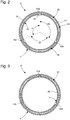
- the figure 2 represents the system 6 in a position of the bezel 14 "at 12 o'clock". In this position, only the first lug 40a of the toothed ring 20 is engaged with the toothing 26. The second and third lugs 40b, 40c are balanced on teeth of the toothed ring 18.
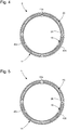
- the system 6 adopts the configuration shown in the figure 3 . In this configuration, only the third lug 40c of the toothed ring 20 is engaged with the toothing 26. The first and second lugs 40a, 40b are balanced on teeth of the toothed ring 18.
- the system 6 adopts the configuration shown in the figure 4 .
- the first and third lugs 40a, 40c are balanced on the teeth of the toothed ring 18.
- the system 6 adopts the configuration shown in the figure 5 .
- the first lug 40a of the toothed ring 20 is again alone in engagement with the toothing 26.
- the second and third lugs 40b, 40c are in equilibrium on the teeth of the toothed ring 18.
- the toothed ring has 40 teeth regularly distributed over its outer periphery, and the spring ring 20 comprises three lugs 40a, 40b, 40c.
- the annular rotating bezel system 6 thus has 120 possible stable positions.
- the spring ring comprises a first lug 40a, a second lug 40b, and a third lug 40c.
- the first and second lugs 40a, 40b are offset from each other by an offset angle ⁇ a
- the second and third lugs 40b, 40c are offset from each other by an offset angle ⁇ b
- the first and third lugs 40a, 40c are offset from each other by an offset angle ⁇ c .
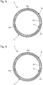
- the figure 6 represents the system 6 in a position of the bezel 14 "at 12 o'clock". In this position, only the first lug 40a of the toothed ring 20 is engaged with the toothing 26. The second and third lugs 40b, 40c are balanced on teeth of the toothed ring 18. When the user grasps of the bezel 14 and rotates it 3 degrees clockwise, the system 6 adopts the configuration shown in the figure 7 . In this configuration, only the third lug 40c of the toothed ring 20 is engaged with the toothing 26. The first and second lugs 40a, 40b are balanced on teeth of the toothed ring 18.
- the system 6 adopts the configuration shown in the figure 8 .
- the first and third lugs 40a, 40c are balanced on the teeth of the toothed ring 18.
- the system 6 adopts the configuration shown in the figure 9 .
- the first lug 40a of the toothed ring 20 is again alone in engagement with the toothing 26.
- the second and third lugs 40b, 40c are in equilibrium on the teeth of the toothed ring 18.
Landscapes
- Physics & Mathematics (AREA)
- General Physics & Mathematics (AREA)
- Adornments (AREA)
- Electric Clocks (AREA)
Abstract
L'invention concerne un système (6) de lunette tournante annulaire destiné à être monté à rotation sur une carrure (4) de boîte de montre (2) à l'intérieur de laquelle est logé un mouvement d'horlogerie qui s'étend dans un plan, comprenant une lunette tournante (14), un anneau denté (18) comprenant une denture (26) munie d'une pluralité de dents régulièrement réparties sur un pourtour de l'anneau denté (18), et un anneau ressort (20) qui s'étend dans un plan dans lequel il est susceptible de se déformer élastiquement selon un rayon, l'anneau ressort (20) coopérant élastiquement avec l'anneau denté (18), ledit anneau denté (18) et ledit anneau ressort (20) étant maintenus selon une direction axiale perpendiculaire au plan du mouvement dans la lunette (14), l'un de l'anneau denté (18) et de l'anneau ressort (20) étant agencé pour être angulairement solidaire de la lunette tournante (14), et l'autre étant agencé pour être angulairement solidaire de la carrure (4), l'anneau ressort (20) comprenant au moins deux ergots (40), chaque ergot (40) étant configuré pour être élastiquement et radialement en prise avec la denture (26) de l'anneau denté (18) dans au moins une position de la lunette (14) ; dans lequel lesdits au moins deux ergots (40) sont décalés entre eux d'un angle de décalage, le ou chaque angle de décalage entre deux ergots successifs présentant une valeur distincte d'un sous-multiple entier de 360 degrés, de manière à ce que, dans chaque position de la lunette (14), un seul ergot (40) soit élastiquement et radialement en prise avec la denture (26) de l'anneau denté (18).The invention relates to a system (6) of an annular rotating bezel intended to be mounted for rotation on a middle part (4) of a watch case (2) inside which is housed a clockwork movement which extends in a plane, comprising a rotating bezel (14), a toothed ring (18) comprising a toothing (26) provided with a plurality of teeth regularly distributed around a periphery of the toothed ring (18), and a spring ring (20 ) which extends in a plane in which it is capable of deforming elastically along a radius, the spring ring (20) cooperating elastically with the toothed ring (18), said toothed ring (18) and said spring ring ( 20) being held in an axial direction perpendicular to the plane of movement in the bezel (14), one of the toothed ring (18) and the spring ring (20) being arranged to be angularly integral with the rotating bezel (14), and the other being arranged to be angularly integral with the square re (4), the spring ring (20) comprising at least two lugs (40), each lug (40) being configured to be elastically and radially engaged with the teeth (26) of the toothed ring (18) in at least one position of the telescope (14); wherein said at least two lugs (40) are offset from each other by an offset angle, the or each offset angle between two successive lugs having a value distinct from an integer sub-multiple of 360 degrees, so that that, in each position of the telescope (14), a single lug (40) is elastically and radially engaged with the teeth (26) of the toothed ring (18).
Description
L'invention concerne un système de lunette tournante annulaire.The invention relates to an annular rotating bezel system.
L'invention concerne également une boîte de montre comprenant une carrure et le système de lunette tournante annulaire monté à rotation sur la carrure.The invention also relates to a watch case comprising a middle part and the annular rotating bezel system rotatably mounted on the middle part.
L'invention concerne en outre une montre comportant la boîte de montre. La montre est par exemple une montre de plongée, sans que cela ne soit limitatif dans le cadre de la présente inventionThe invention further relates to a watch comprising the watch case. The watch is for example a diving watch, without this being limiting in the context of the present invention
Des systèmes de lunettes tournantes annulaires connus comprennent une lunette tournante, un anneau denté, et un anneau ressort. Un tel système de lunette tournante est par exemple décrit dans le document brevet
L'invention a donc pour but de fournir un système de lunette tournante annulaire permettant, à nombre de dents égal pour l'anneau denté par rapport aux systèmes de l'art antérieur, d'obtenir un plus grand nombre de positions stables possibles pour la lunette tournante, et palliant les inconvénients susmentionnés de l'état de la technique.The object of the invention is therefore to provide an annular rotating bezel system making it possible, with an equal number of teeth for the toothed ring compared to the systems of the prior art, to obtain a greater number of stable positions possible for the rotating bezel, and overcoming the aforementioned drawbacks of the state of the art.
A cet effet, l'invention concerne un système de lunette tournante annulaire qui comprend les caractéristiques mentionnées dans la revendication indépendante 1.To this end, the invention relates to an annular rotating bezel system which comprises the characteristics mentioned in independent claim 1.
Des formes particulières du système sont définies dans les revendications dépendantes 2 à 16.Particular forms of the system are defined in
Un avantage de la présente invention est de permettre, à nombre de dents égal pour l'anneau denté par rapport aux systèmes de l'art antérieur, d'obtenir un plus grand nombre de positions stables possibles pour la lunette tournante. En effet, grâce à la configuration selon laquelle le ou chaque angle de décalage entre deux ergots successifs présente une valeur distincte d'un sous-multiple entier de 360 degrés, un seul ergot est élastiquement et radialement en prise avec la denture de l'anneau denté dans chaque position de la lunette. Le nombre de positions possibles au total pour la lunette est alors donné par le résultat de la multiplication entre le nombre d'ergots sur l'anneau ressort, et le nombre de dents sur l'anneau denté. Ceci permet d'obtenir un plus grand nombre de positions stables possibles pour la lunette tournante.An advantage of the present invention is to allow, with an equal number of teeth for the toothed ring compared to the systems of the prior art, to obtain a greater number of possible stable positions for the rotating bezel. Indeed, thanks to the configuration according to which the or each angle of offset between two successive lugs has a value distinct from an integer sub-multiple of 360 degrees, a single lug is elastically and radially engaged with the teeth of the ring toothed in each position of the telescope. Number of total possible positions for the telescope is then given by the result of the multiplication between the number of pins on the spring ring, and the number of teeth on the toothed ring. This allows to obtain a greater number of possible stable positions for the rotating bezel.
Inversement, il est possible par exemple, grâce au système selon l'invention, d'augmenter la taille des dents et de réduire leur nombre sur l'anneau denté, en vue de diminuer leur usure, et ceci tout en conservant un nombre de positions stables pour la lunette identique à celui des systèmes de l'art antérieur.Conversely, it is possible for example, thanks to the system according to the invention, to increase the size of the teeth and reduce their number on the toothed ring, in order to reduce their wear, and this while retaining a number of positions stable for the scope identical to that of the systems of the prior art.
Avantageusement, l'anneau ressort comprend au moins deux portions amincies agencées pour augmenter la flexibilité de l'anneau ressort dans son plan, chaque ergot s'étendant à partir d'une des portions amincies. Ceci permet d'augmenter la flexibilité de l'anneau ressort dans son plan. En effet, grâce aux portions amincies qu'il présente, l'anneau ressort travaille en flexion dans son plan, permettant aux ergots qu'il porte de s'engrener et de se dégrener de l'anneau denté selon la rotation de la lunette. Ceci permet de réduire la largeur nécessaire au fonctionnement de l'anneau ressort dans le système, et donc d'obtenir un gain en encombrement en largeur de l'ensemble.Advantageously, the spring ring comprises at least two thinned portions arranged to increase the flexibility of the spring ring in its plane, each lug extending from one of the thinned portions. This increases the flexibility of the spring ring in its plane. Indeed, thanks to the thinned portions which it presents, the spring ring works in bending in its plane, allowing the pins which it carries to mesh and to degenerate from the toothed ring according to the rotation of the telescope. This makes it possible to reduce the width necessary for the operation of the spring ring in the system, and therefore to obtain a gain in overall dimensions in width of the assembly.
Avantageusement, la lunette tournante comprend au moins un bourrelet s'étendant sur une face latérale interne de la lunette, et l'anneau ressort présente, sur un pourtour extérieur, au moins une échancrure dans laquelle le bourrelet de la lunette est engagé. Ceci permet de lier facilement en rotation l'anneau ressort à la lunette tournante, tout en facilitant le positionnement de l'anneau ressort dans la lunette.Advantageously, the rotating bezel comprises at least one bead extending over an internal lateral face of the bezel, and the spring ring has, on an outer periphery, at least one notch in which the bead of the bezel is engaged. This allows the spring ring to be easily linked in rotation to the rotating bezel, while facilitating the positioning of the spring ring in the bezel.
Avantageusement, l'anneau denté présente, sur un pourtour intérieur, au moins un bourrelet destiné à être reçu dans une échancrure prévue dans une surface extérieure cylindrique de la carrure. Ceci permet une solidarisation angulaire aisée de l'anneau denté à la carrure, tout en facilitant le positionnement de l'anneau denté sur la carrure et en permettant de guider le système de lunette tournante pour son montage sur la carrure.Advantageously, the toothed ring has, on an inner periphery, at least one bead intended to be received in a notch provided in a cylindrical outer surface of the middle part. This allows easy angular attachment of the toothed ring to the middle part, while facilitating the positioning of the toothed ring on the middle part and to guide the rotating bezel system for mounting on the middle.
Selon un premier exemple de réalisation de l'invention, les dents de l'anneau denté et les ergots de l'anneau ressort présentent chacun(e) une forme asymétrique dans le plan défini par l'anneau ressort. Dans ce premier exemple de réalisation, l'anneau ressort peut tourner par rapport à l'anneau denté dans un seul sens prédéfini : horaire ou anti-horaire selon la forme choisie pour les dents. Ce premier exemple de réalisation de l'invention correspond donc à une lunette tournante unidirectionnelle.According to a first embodiment of the invention, the teeth of the toothed ring and the lugs of the spring ring each have an asymmetrical shape in the plane defined by the spring ring. In this first exemplary embodiment, the spring ring can rotate with respect to the toothed ring in only one predefined direction: clockwise or counterclockwise depending on the shape chosen for the teeth. This first embodiment of the invention therefore corresponds to a unidirectional rotating bezel.
Selon un deuxième exemple de réalisation de l'invention, les dents de l'anneau denté et les ergots de l'anneau ressort présentent chacun(e) une forme symétrique dans le plan défini par l'anneau ressort. Dans ce deuxième exemple de réalisation, l'anneau ressort peut tourner par rapport à l'anneau denté dans l'un ou l'autre des deux sens : horaire ou anti-horaire. Ce deuxième exemple de réalisation de l'invention correspond donc à une lunette tournante bidirectionnelle.According to a second embodiment of the invention, the teeth of the toothed ring and the lugs of the spring ring each have a symmetrical shape in the plane defined by the spring ring. In this second embodiment, the spring ring can rotate relative to the toothed ring in one or the other of the two directions: clockwise or counterclockwise. This second embodiment of the invention therefore corresponds to a bidirectional rotating bezel.
Avantageusement, le système de lunette tournante annulaire est formé d'un module indépendant, ledit module étant configuré pour être clippé sur la carrure. Ceci permet d'obtenir un montage simple et pratique du système de lunette tournante sur la carrure, permettant également un démontage aisé. Ceci permet de simplifier le procédé de fabrication de la boîte de montre. Le système de montage par clippage utilisé forme un système de crochement libre.Advantageously, the annular rotating bezel system is formed by an independent module, said module being configured to be clipped onto the middle part. This makes it possible to obtain a simple and practical assembly of the rotating bezel system on the middle part, also allowing easy disassembly. This simplifies the manufacturing process of the watch case. The clip-on mounting system used forms a free hanging system.
A cet effet, l'invention concerne également une boîte de montre comprenant le système de lunette tournante annulaire décrit ci-dessus, et qui comprend les caractéristiques mentionnées dans la revendication dépendante 17.To this end, the invention also relates to a watch case comprising the annular rotating bezel system described above, and which comprises the characteristics mentioned in dependent claim 17.
Une forme particulière de la boîte de montre est définie dans la revendication dépendante 18.A particular form of the watch case is defined in
A cet effet, l'invention concerne également une montre comportant la boîte de montre décrite ci-dessus, et qui comprend les caractéristiques mentionnées dans la revendication dépendante 19.To this end, the invention also relates to a watch comprising the watch case described above, and which comprises the characteristics mentioned in dependent claim 19.
Les buts, avantages et caractéristiques du système de lunette tournante annulaire selon l'invention apparaîtront mieux dans la description suivante sur la base d'au moins une forme d'exécution non limitative illustrée par les dessins sur lesquels :
- la
figure 1 est une vue en perspective éclatée du système de lunette tournante annulaire selon l'invention, comprenant un anneau ressort et un anneau denté ; - les
figures 2 à 5 sont des vues de dessus du système de lunette tournante annulaire de lafigure 1 , selon un premier mode de réalisation de l'invention, et dans différentes positions de la lunette ; et - les
figures 6 à 9 sont des vues de dessus du système de lunette tournante annulaire de lafigure 1 , selon un deuxième mode de réalisation de l'invention, et dans différentes positions de la lunette.
- the
figure 1 is an exploded perspective view of the annular rotating bezel system according to the invention, comprising a spring ring and a toothed ring; - the
figures 2 to 5 are top views of the annular rotating bezel system of thefigure 1 , according to a first embodiment of the invention, and in different positions of the telescope; and - the
figures 6 to 9 are top views of the annular rotating bezel system of thefigure 1 , according to a second embodiment of the invention, and in different positions of the telescope.
La
Comme illustré sur la
Le système de lunette tournante annulaire 6 comprend une lunette tournante 14, un anneau denté 18 et un anneau ressort 20. De préférence, le système 6 comprend en outre une bague annulaire de maintien 16. De préférence encore, le système 6 comprend également un anneau de décor 22 engagé à force sur la lunette tournante 14. L'anneau de décor 22 porte par exemple des graduations, typiquement des graduations de plongée dans le cas d'une montre 1 de plongée. L'anneau de décor 22 est par exemple en céramique.The annular
La lunette tournante 14 est de forme annulaire et comprend une face supérieure 23a visible par l'utilisateur et une face inférieure 23b. Comme illustré sur la
La bague annulaire 16 maintient l'anneau denté 18 et l'anneau ressort 20 dans la lunette 14, selon une direction axiale perpendiculaire au plan du mouvement horloger. Ceci permet de faciliter le montage de la lunette tournante 14 sur la carrure 4. De préférence, la bague annulaire 16 est chassée dans la lunette tournante 14, la solidarisant à cette dernière. Dans une variante de réalisation non représentée sur les figures, la bague annulaire 16 est solidarisée à la carrure 4.The
La bague annulaire 16 repose sur la base 12b de la carrure 4, et entoure ainsi la surface extérieure cylindrique 8 de la carrure 4. La bague annulaire 16 est configurée pour coopérer avec la surface extérieure cylindrique 8 pour permettre la rotation de la lunette tournante 14 sur la carrure 4. La bague annulaire de maintien 16 est par exemple une bague plate. Selon d'autres variantes de réalisation de l'invention la bague annulaire de maintien peut comprendre une simple bague annulaire de section rectangulaire sur tout son pourtour chassée dans la lunette 14.The
L'anneau denté 18 comprend une denture 26. La denture 26 est munie de plusieurs dents régulièrement réparties sur un pourtour de l'anneau denté 18, typiquement sur un pourtour extérieur, sur 360 degrés. De préférence, l'anneau denté 18 présente en outre, sur son pourtour intérieur, au moins un bourrelet 34 reçu dans une échancrure 36 prévue dans la surface extérieure cylindrique 8 de la carrure 4. Dans les exemples de réalisation illustrés sur les
L'anneau denté 18 est formé d'une seule pièce de matière. L'anneau denté 18 est par exemple constitué d'un alliage métallique, notamment un alliage à base de cobalt (40%Co, 20%Cr, 16%Ni et. 7%Mo) dénommé commercialement phynox ou de l'acier typiquement un acier inoxydable par exemple 316L. En variante, l'anneau denté 18 peut être constitué d'un matériau thermoplastique, notamment un matériau thermoplastique semi-cristallin thermostable tel que par exemple du polyarylamide (Ixef®), du polyétheréthercétone (PEEK) ou encore en un matériau céramique comme de la zircone ou de l'alumine.The
Comme visible aux
L'anneau ressort 20 s'étend dans un plan dans lequel il est susceptible de se déformer élastiquement selon un rayon. L'anneau ressort 20 coopère élastiquement avec l'anneau denté 18. Pour ce faire, l'anneau ressort 20 comprend au moins deux ergots 40, chaque ergot 40 étant configuré pour être élastiquement et radialement en prise avec la denture 26 de l'anneau denté 18 dans au moins une position de la lunette 14. Dans les exemples de réalisation illustrés sur les
De préférence, l'anneau ressort 20 comprend au moins deux portions amincies 38. Chaque ergot 40 s'étend à partir d'une des portions amincies 38. Dans les exemples de réalisation illustrés sur les
De préférence, comme illustré sur les
De préférence encore, l'anneau ressort 20 présente sur son pourtour extérieur, au moins une échancrure 42 dans laquelle un bourrelet de la lunette 14 est engagé pour lier ces deux éléments en rotation. Dans les exemples de réalisation illustrés sur les
L'anneau ressort 20 est formé d'une seule pièce de matière. L'anneau ressort 20 est par exemple constitué d'un alliage métallique ayant de bonnes propriétés ressort c'est-à-dire qui se déforme facilement de manière élastique tout en pouvant se déformer de manière importante sans subir de déformation plastique, notamment du phynox® ou encore d'alliages métalliques amorphes. Bien entendu, l'anneau ressort 20 peut aussi, en variante, être réalisé dans un matériau synthétique.The
Selon un premier exemple de réalisation, les dents de l'anneau denté 18 et les ergots 40 de l'anneau ressort 20 présentent une forme asymétrique dans le plan défini par l'anneau ressort 20. La forme asymétrique est par exemple une forme dite « dent de loup », c'est-à-dire que les dents et les ergots présentent sensiblement une forme de triangle rectangle. En position d'engrainement d'un ergot 40, l'hypoténuse du triangle formé par cet ergot 40 de l'anneau ressort s'étend le long de l'hypoténuse du triangle formé par une des dents de l'anneau denté 18. Dans cet exemple de réalisation, l'anneau ressort 20 peut tourner par rapport à l'anneau denté 18 dans un seul sens prédéfini : horaire ou anti-horaire selon la forme choisie pour les dents et les ergots. Ce premier exemple de réalisation de l'invention correspond donc à une lunette tournante 14 unidirectionnelle.According to a first embodiment, the teeth of the
Selon un deuxième exemple de réalisation, les dents de l'anneau denté 18 et les ergots 40 de l'anneau ressort 20 présentent une forme symétrique dans le plan défini par l'anneau ressort 20. La forme symétrique est par exemple une forme de triangle isocèle ou de triangle équilatéral. Dans cet exemple de réalisation, l'anneau ressort 20 peut tourner par rapport à l'anneau denté 18 dans l'un ou l'autre des deux sens : horaire ou anti-horaire. Ce deuxième exemple de réalisation de l'invention correspond donc à une lunette tournante 14 bidirectionnelle.According to a second embodiment, the teeth of the
Un premier mode de réalisation de l'invention va maintenant être décrit en référence aux
La
Un deuxième mode de réalisation de l'invention va maintenant être décrit en référence aux
La
La description précédente du système de lunette tournante annulaire selon l'invention a été faite en référence à un anneau denté angulairement solidaire de la carrure, et à un anneau ressort angulairement solidaire de la lunette tournante. Toutefois, l'homme du métier comprendra que la configuration inverse est possible sans sortir du cadre de la présente invention, c'est-à-dire que l'anneau denté peut être angulairement solidaire de la lunette tournante, et l'anneau ressort angulairement solidaire de la carrure. En outre, bien que l'invention ait été décrite en référence à un anneau ressort muni de trois ergots, l'invention s'applique de la même manière pour des systèmes de lunette tournante munis d'anneaux ressort comprenant deux ergots, ou encore des anneaux ressort comprenant quatre ergots et plus.The previous description of the annular rotating bezel system according to the invention was made with reference to a toothed ring angularly secured to the middle part, and to a spring ring angularly secured to the rotating bezel. However, those skilled in the art will understand that the reverse configuration is possible without departing from the scope of the present invention, that is to say that the toothed ring can be angularly secured to the rotating bezel, and the ring emerges angularly secured to the middle part. In addition, although the invention has been described with reference to a spring ring provided with three lugs, the invention applies in the same way for rotating bezel systems provided with spring rings comprising two lugs, or even spring rings with four or more lugs.
Claims (19)
caractérisé en ce que lesdits au moins deux ergots (40 ; 40a-40c) sont décalés entre eux d'un angle de décalage (ϑa, ϑb, ϑc), le ou chaque angle de décalage (ϑa, ϑb, ϑc) entre deux ergots successifs présentant une valeur distincte d'un sous-multiple entier de 360 degrés, de manière à ce que, dans chaque position de la lunette (14), un seul ergot (40 ; 40a-40c) soit élastiquement et radialement en prise avec la denture (26) de l'anneau denté (18).System (6) of an annular rotating bezel intended to be mounted for rotation on a middle part (4) of a watch case (2) inside which is housed a clockwork movement which extends in a plane, comprising a rotating bezel (14), a toothed ring (18) comprising a toothing (26) provided with a plurality of teeth regularly distributed around a periphery of the toothed ring (18), and a spring ring (20) which extends in a plane in which it is capable of deforming elastically along a radius, the spring ring (20) cooperating elastically with the toothed ring (18), said toothed ring (18) and said spring ring (20) being held according to an axial direction perpendicular to the plane of movement in the bezel (14), one of the toothed ring (18) and of the spring ring (20) being arranged to be angularly integral with the rotating bezel (14), and the other being arranged to be angularly integral with the middle part (4), the ring emerges (20) comprising at least two lugs (40; 40a-40c), each lug (40; 40a-40c) being configured to be elastically and radially engaged with the teeth (26) of the toothed ring (18) in at least one position of the telescope (14);
characterized in that said at least two lugs (40; 40a-40c) are offset between them by an offset angle (ϑ a , ϑ b , ϑ c ), the or each offset angle (ϑ a , ϑ b , ϑ c ) between two successive lugs having a value distinct from an integer sub-multiple of 360 degrees, so that, in each position of the telescope (14), a single lug (40; 40a-40c) is elastically and radially engaged with the toothing (26) of the toothed ring (18).
Priority Applications (4)
| Application Number | Priority Date | Filing Date | Title |
|---|---|---|---|
| EP18187998.2A EP3608730B1 (en) | 2018-08-08 | 2018-08-08 | Annular rotating bezel system comprising a spring ring provided with at least two lugs |
| US16/458,638 US11243496B2 (en) | 2018-08-08 | 2019-07-01 | Annular rotating bezel system comprising a spring ring provided with at least two lugs |
| JP2019128116A JP6749454B2 (en) | 2018-08-08 | 2019-07-10 | Annular rotating bezel system having a spring ring with at least two protrusions |
| CN201910720875.1A CN110824882B (en) | 2018-08-08 | 2019-08-06 | Ring-shaped rotary bezel system comprising a spring ring provided with at least two lugs |
Applications Claiming Priority (1)
| Application Number | Priority Date | Filing Date | Title |
|---|---|---|---|
| EP18187998.2A EP3608730B1 (en) | 2018-08-08 | 2018-08-08 | Annular rotating bezel system comprising a spring ring provided with at least two lugs |
Publications (2)
| Publication Number | Publication Date |
|---|---|
| EP3608730A1 true EP3608730A1 (en) | 2020-02-12 |
| EP3608730B1 EP3608730B1 (en) | 2021-05-05 |
Family
ID=63174103
Family Applications (1)
| Application Number | Title | Priority Date | Filing Date |
|---|---|---|---|
| EP18187998.2A Active EP3608730B1 (en) | 2018-08-08 | 2018-08-08 | Annular rotating bezel system comprising a spring ring provided with at least two lugs |
Country Status (4)
| Country | Link |
|---|---|
| US (1) | US11243496B2 (en) |
| EP (1) | EP3608730B1 (en) |
| JP (1) | JP6749454B2 (en) |
| CN (1) | CN110824882B (en) |
Cited By (2)
| Publication number | Priority date | Publication date | Assignee | Title |
|---|---|---|---|---|
| EP4020097A1 (en) | 2020-12-22 | 2022-06-29 | Rolex Sa | Spring for notching system and timepiece notching system |
| EP4020098A1 (en) | 2020-12-22 | 2022-06-29 | Rolex Sa | Spring for notching system and timepiece notching system |
Families Citing this family (2)
| Publication number | Priority date | Publication date | Assignee | Title |
|---|---|---|---|---|
| EP3800514B1 (en) * | 2019-10-04 | 2024-01-17 | Comadur S.A. | Spring ring of a snap fitting of a rotating bezel |
| EP4202569A1 (en) | 2021-12-21 | 2023-06-28 | Montres Breguet S.A. | Watch case with rotating bezel |
Citations (2)
| Publication number | Priority date | Publication date | Assignee | Title |
|---|---|---|---|---|
| EP2672333A1 (en) | 2012-06-06 | 2013-12-11 | Omega SA | Rotating bezel system |
| CH712742A2 (en) * | 2016-07-26 | 2018-01-31 | Omega Sa | Subset of clothing for a timepiece, in particular a watch, or for jewelery. |
Family Cites Families (10)
| Publication number | Priority date | Publication date | Assignee | Title |
|---|---|---|---|---|
| CH683481B5 (en) | 1992-05-01 | 1994-09-30 | Ebauchesfabrik Eta Ag | Timepiece including a rotating bezel. |
| CH686470B5 (en) * | 1994-06-09 | 1996-10-15 | Rolex Montres | Box rotating bezel watch. |
| EP0770937B1 (en) | 1995-10-27 | 2000-01-26 | Eta SA Fabriques d'Ebauches | Timepiece provided with a rotatable bezel |
| CH690140A5 (en) * | 1996-03-05 | 2000-05-15 | Smh Management Services Ag | watch box with a rotating bezel. |
| IT1285147B1 (en) | 1996-05-31 | 1998-06-03 | Panerai Off Srl | IMPROVEMENTS IN DIVER-TYPE WATCHES INCORPORATING A REMOVABLE UNI-DIRECTIONAL ROTATING BEZEL FIXING SYSTEM |
| EP1416341B1 (en) | 2003-09-03 | 2006-05-17 | Rolex S.A. | Connection device between a bezel and a watch case |
| JP2010090526A (en) | 2008-09-12 | 2010-04-22 | Toray Ind Inc | Microfine fiber and thermoplastic resin composition containing the same |
| EP2874022B1 (en) | 2013-11-15 | 2016-10-26 | Chopard Technologies SA | Watch case including a bayonet connection |
| JP6741397B2 (en) * | 2014-02-10 | 2020-08-19 | ロレックス・ソシエテ・アノニムRolex Sa | Mobile watch side and watch |
| CN104730903B (en) | 2015-03-24 | 2017-05-24 | 惠州Tcl移动通信有限公司 | Watchcase assembly and watch |
-
2018
- 2018-08-08 EP EP18187998.2A patent/EP3608730B1/en active Active
-
2019
- 2019-07-01 US US16/458,638 patent/US11243496B2/en active Active
- 2019-07-10 JP JP2019128116A patent/JP6749454B2/en active Active
- 2019-08-06 CN CN201910720875.1A patent/CN110824882B/en active Active
Patent Citations (2)
| Publication number | Priority date | Publication date | Assignee | Title |
|---|---|---|---|---|
| EP2672333A1 (en) | 2012-06-06 | 2013-12-11 | Omega SA | Rotating bezel system |
| CH712742A2 (en) * | 2016-07-26 | 2018-01-31 | Omega Sa | Subset of clothing for a timepiece, in particular a watch, or for jewelery. |
Cited By (3)
| Publication number | Priority date | Publication date | Assignee | Title |
|---|---|---|---|---|
| EP4020097A1 (en) | 2020-12-22 | 2022-06-29 | Rolex Sa | Spring for notching system and timepiece notching system |
| EP4020098A1 (en) | 2020-12-22 | 2022-06-29 | Rolex Sa | Spring for notching system and timepiece notching system |
| US11977355B2 (en) | 2020-12-22 | 2024-05-07 | Rolex Sa | Spring for a notching system and timepiece notching system |
Also Published As
| Publication number | Publication date |
|---|---|
| US11243496B2 (en) | 2022-02-08 |
| JP6749454B2 (en) | 2020-09-02 |
| JP2020024192A (en) | 2020-02-13 |
| CN110824882A (en) | 2020-02-21 |
| US20200050153A1 (en) | 2020-02-13 |
| CN110824882B (en) | 2021-04-27 |
| EP3608730B1 (en) | 2021-05-05 |
Similar Documents
| Publication | Publication Date | Title |
|---|---|---|
| EP3608730B1 (en) | Annular rotating bezel system comprising a spring ring provided with at least two lugs | |
| EP3543800B1 (en) | Annular rotating bezel system comprising a spring ring | |
| EP1738229B1 (en) | Crown for timepiece, comprising a disengaging device | |
| EP2859412B1 (en) | Rotating bezel system | |
| EP2876504B1 (en) | Screwless clock stud holder | |
| EP2743783B1 (en) | Connection between a dial and an ebauche of a timepiece | |
| EP0004246B2 (en) | Device for mounting accessories on camera objectives and a hood to be used with this device | |
| EP0823979B1 (en) | Watch case with a rotary rim | |
| EP2230572A1 (en) | Radial gripping system for a timepiece component | |
| EP3543799B1 (en) | Annular ring for holding a rotating bezel system | |
| FR3062218A1 (en) | ATTACHMENT OF "CAPSLOCK" WATCH | |
| CH715239A2 (en) | Annular rotating bezel system comprising a spring ring provided with at least two lugs. | |
| EP3543798B1 (en) | Annular rotating bezel system comprising at least one resilient arm | |
| EP3179315A1 (en) | Stud support with secure mounting | |
| EP3719583B1 (en) | Mechanical braking device for a clock mobile | |
| EP3432081B1 (en) | Timepiece assembly | |
| WO2007105043A2 (en) | Timepiece with rotating bezel | |
| CH714803A2 (en) | An annular rotating bezel system comprising at least one elastic arm. | |
| CH714807A2 (en) | An annular rotating bezel system comprising a spring ring. | |
| EP3037896B1 (en) | Detachable stud support | |
| CH714808A2 (en) | Ring ring for maintaining a rotating bezel system. | |
| EP0470018B1 (en) | Frictional rotary control | |
| CH711900A2 (en) | Piton mount with secure mounting. | |
| WO2021228938A1 (en) | Watch case comprising a rotating element | |
| CH715697A2 (en) | Watch case provided with an annular ring, and wristwatch and assembly kit for a wristwatch comprising it. |
Legal Events
| Date | Code | Title | Description |
|---|---|---|---|
| PUAI | Public reference made under article 153(3) epc to a published international application that has entered the european phase |
Free format text: ORIGINAL CODE: 0009012 |
|
| STAA | Information on the status of an ep patent application or granted ep patent |
Free format text: STATUS: THE APPLICATION HAS BEEN PUBLISHED |
|
| AK | Designated contracting states |
Kind code of ref document: A1 Designated state(s): AL AT BE BG CH CY CZ DE DK EE ES FI FR GB GR HR HU IE IS IT LI LT LU LV MC MK MT NL NO PL PT RO RS SE SI SK SM TR |
|
| AX | Request for extension of the european patent |
Extension state: BA ME |
|
| STAA | Information on the status of an ep patent application or granted ep patent |
Free format text: STATUS: REQUEST FOR EXAMINATION WAS MADE |
|
| 17P | Request for examination filed |
Effective date: 20200812 |
|
| RBV | Designated contracting states (corrected) |
Designated state(s): AL AT BE BG CH CY CZ DE DK EE ES FI FR GB GR HR HU IE IS IT LI LT LU LV MC MK MT NL NO PL PT RO RS SE SI SK SM TR |
|
| GRAJ | Information related to disapproval of communication of intention to grant by the applicant or resumption of examination proceedings by the epo deleted |
Free format text: ORIGINAL CODE: EPIDOSDIGR1 |
|
| STAA | Information on the status of an ep patent application or granted ep patent |
Free format text: STATUS: GRANT OF PATENT IS INTENDED |
|
| GRAP | Despatch of communication of intention to grant a patent |
Free format text: ORIGINAL CODE: EPIDOSNIGR1 |
|
| STAA | Information on the status of an ep patent application or granted ep patent |
Free format text: STATUS: GRANT OF PATENT IS INTENDED |
|
| INTG | Intention to grant announced |
Effective date: 20201217 |
|
| GRAS | Grant fee paid |
Free format text: ORIGINAL CODE: EPIDOSNIGR3 |
|
| GRAA | (expected) grant |
Free format text: ORIGINAL CODE: 0009210 |
|
| STAA | Information on the status of an ep patent application or granted ep patent |
Free format text: STATUS: THE PATENT HAS BEEN GRANTED |
|
| AK | Designated contracting states |
Kind code of ref document: B1 Designated state(s): AL AT BE BG CH CY CZ DE DK EE ES FI FR GB GR HR HU IE IS IT LI LT LU LV MC MK MT NL NO PL PT RO RS SE SI SK SM TR |
|
| REG | Reference to a national code |
Ref country code: GB Ref legal event code: FG4D Free format text: NOT ENGLISH |
|
| REG | Reference to a national code |
Ref country code: CH Ref legal event code: EP |
|
| REG | Reference to a national code |
Ref country code: AT Ref legal event code: REF Ref document number: 1390575 Country of ref document: AT Kind code of ref document: T Effective date: 20210515 |
|
| REG | Reference to a national code |
Ref country code: IE Ref legal event code: FG4D Free format text: LANGUAGE OF EP DOCUMENT: FRENCH |
|
| REG | Reference to a national code |
Ref country code: DE Ref legal event code: R096 Ref document number: 602018016519 Country of ref document: DE |
|
| REG | Reference to a national code |
Ref country code: LT Ref legal event code: MG9D |
|
| REG | Reference to a national code |
Ref country code: AT Ref legal event code: MK05 Ref document number: 1390575 Country of ref document: AT Kind code of ref document: T Effective date: 20210505 |
|
| PG25 | Lapsed in a contracting state [announced via postgrant information from national office to epo] |
Ref country code: AT Free format text: LAPSE BECAUSE OF FAILURE TO SUBMIT A TRANSLATION OF THE DESCRIPTION OR TO PAY THE FEE WITHIN THE PRESCRIBED TIME-LIMIT Effective date: 20210505 Ref country code: BG Free format text: LAPSE BECAUSE OF FAILURE TO SUBMIT A TRANSLATION OF THE DESCRIPTION OR TO PAY THE FEE WITHIN THE PRESCRIBED TIME-LIMIT Effective date: 20210805 Ref country code: HR Free format text: LAPSE BECAUSE OF FAILURE TO SUBMIT A TRANSLATION OF THE DESCRIPTION OR TO PAY THE FEE WITHIN THE PRESCRIBED TIME-LIMIT Effective date: 20210505 Ref country code: LT Free format text: LAPSE BECAUSE OF FAILURE TO SUBMIT A TRANSLATION OF THE DESCRIPTION OR TO PAY THE FEE WITHIN THE PRESCRIBED TIME-LIMIT Effective date: 20210505 Ref country code: FI Free format text: LAPSE BECAUSE OF FAILURE TO SUBMIT A TRANSLATION OF THE DESCRIPTION OR TO PAY THE FEE WITHIN THE PRESCRIBED TIME-LIMIT Effective date: 20210505 |
|
| PG25 | Lapsed in a contracting state [announced via postgrant information from national office to epo] |
Ref country code: GR Free format text: LAPSE BECAUSE OF FAILURE TO SUBMIT A TRANSLATION OF THE DESCRIPTION OR TO PAY THE FEE WITHIN THE PRESCRIBED TIME-LIMIT Effective date: 20210806 Ref country code: IS Free format text: LAPSE BECAUSE OF FAILURE TO SUBMIT A TRANSLATION OF THE DESCRIPTION OR TO PAY THE FEE WITHIN THE PRESCRIBED TIME-LIMIT Effective date: 20210905 Ref country code: SE Free format text: LAPSE BECAUSE OF FAILURE TO SUBMIT A TRANSLATION OF THE DESCRIPTION OR TO PAY THE FEE WITHIN THE PRESCRIBED TIME-LIMIT Effective date: 20210505 Ref country code: RS Free format text: LAPSE BECAUSE OF FAILURE TO SUBMIT A TRANSLATION OF THE DESCRIPTION OR TO PAY THE FEE WITHIN THE PRESCRIBED TIME-LIMIT Effective date: 20210505 Ref country code: PT Free format text: LAPSE BECAUSE OF FAILURE TO SUBMIT A TRANSLATION OF THE DESCRIPTION OR TO PAY THE FEE WITHIN THE PRESCRIBED TIME-LIMIT Effective date: 20210906 Ref country code: PL Free format text: LAPSE BECAUSE OF FAILURE TO SUBMIT A TRANSLATION OF THE DESCRIPTION OR TO PAY THE FEE WITHIN THE PRESCRIBED TIME-LIMIT Effective date: 20210505 Ref country code: NO Free format text: LAPSE BECAUSE OF FAILURE TO SUBMIT A TRANSLATION OF THE DESCRIPTION OR TO PAY THE FEE WITHIN THE PRESCRIBED TIME-LIMIT Effective date: 20210805 Ref country code: LV Free format text: LAPSE BECAUSE OF FAILURE TO SUBMIT A TRANSLATION OF THE DESCRIPTION OR TO PAY THE FEE WITHIN THE PRESCRIBED TIME-LIMIT Effective date: 20210505 |
|
| REG | Reference to a national code |
Ref country code: NL Ref legal event code: MP Effective date: 20210505 |
|
| PG25 | Lapsed in a contracting state [announced via postgrant information from national office to epo] |
Ref country code: NL Free format text: LAPSE BECAUSE OF FAILURE TO SUBMIT A TRANSLATION OF THE DESCRIPTION OR TO PAY THE FEE WITHIN THE PRESCRIBED TIME-LIMIT Effective date: 20210505 |
|
| PG25 | Lapsed in a contracting state [announced via postgrant information from national office to epo] |
Ref country code: RO Free format text: LAPSE BECAUSE OF FAILURE TO SUBMIT A TRANSLATION OF THE DESCRIPTION OR TO PAY THE FEE WITHIN THE PRESCRIBED TIME-LIMIT Effective date: 20210505 Ref country code: DK Free format text: LAPSE BECAUSE OF FAILURE TO SUBMIT A TRANSLATION OF THE DESCRIPTION OR TO PAY THE FEE WITHIN THE PRESCRIBED TIME-LIMIT Effective date: 20210505 Ref country code: CZ Free format text: LAPSE BECAUSE OF FAILURE TO SUBMIT A TRANSLATION OF THE DESCRIPTION OR TO PAY THE FEE WITHIN THE PRESCRIBED TIME-LIMIT Effective date: 20210505 Ref country code: SM Free format text: LAPSE BECAUSE OF FAILURE TO SUBMIT A TRANSLATION OF THE DESCRIPTION OR TO PAY THE FEE WITHIN THE PRESCRIBED TIME-LIMIT Effective date: 20210505 Ref country code: SK Free format text: LAPSE BECAUSE OF FAILURE TO SUBMIT A TRANSLATION OF THE DESCRIPTION OR TO PAY THE FEE WITHIN THE PRESCRIBED TIME-LIMIT Effective date: 20210505 Ref country code: EE Free format text: LAPSE BECAUSE OF FAILURE TO SUBMIT A TRANSLATION OF THE DESCRIPTION OR TO PAY THE FEE WITHIN THE PRESCRIBED TIME-LIMIT Effective date: 20210505 Ref country code: ES Free format text: LAPSE BECAUSE OF FAILURE TO SUBMIT A TRANSLATION OF THE DESCRIPTION OR TO PAY THE FEE WITHIN THE PRESCRIBED TIME-LIMIT Effective date: 20210505 |
|
| REG | Reference to a national code |
Ref country code: DE Ref legal event code: R097 Ref document number: 602018016519 Country of ref document: DE |
|
| PLBE | No opposition filed within time limit |
Free format text: ORIGINAL CODE: 0009261 |
|
| STAA | Information on the status of an ep patent application or granted ep patent |
Free format text: STATUS: NO OPPOSITION FILED WITHIN TIME LIMIT |
|
| PG25 | Lapsed in a contracting state [announced via postgrant information from national office to epo] |
Ref country code: MC Free format text: LAPSE BECAUSE OF FAILURE TO SUBMIT A TRANSLATION OF THE DESCRIPTION OR TO PAY THE FEE WITHIN THE PRESCRIBED TIME-LIMIT Effective date: 20210505 |
|
| 26N | No opposition filed |
Effective date: 20220208 |
|
| REG | Reference to a national code |
Ref country code: BE Ref legal event code: MM Effective date: 20210831 |
|
| PG25 | Lapsed in a contracting state [announced via postgrant information from national office to epo] |
Ref country code: IS Free format text: LAPSE BECAUSE OF FAILURE TO SUBMIT A TRANSLATION OF THE DESCRIPTION OR TO PAY THE FEE WITHIN THE PRESCRIBED TIME-LIMIT Effective date: 20210905 Ref country code: LU Free format text: LAPSE BECAUSE OF NON-PAYMENT OF DUE FEES Effective date: 20210808 Ref country code: AL Free format text: LAPSE BECAUSE OF FAILURE TO SUBMIT A TRANSLATION OF THE DESCRIPTION OR TO PAY THE FEE WITHIN THE PRESCRIBED TIME-LIMIT Effective date: 20210505 |
|
| PG25 | Lapsed in a contracting state [announced via postgrant information from national office to epo] |
Ref country code: IT Free format text: LAPSE BECAUSE OF FAILURE TO SUBMIT A TRANSLATION OF THE DESCRIPTION OR TO PAY THE FEE WITHIN THE PRESCRIBED TIME-LIMIT Effective date: 20210505 Ref country code: IE Free format text: LAPSE BECAUSE OF NON-PAYMENT OF DUE FEES Effective date: 20210808 Ref country code: BE Free format text: LAPSE BECAUSE OF NON-PAYMENT OF DUE FEES Effective date: 20210831 |
|
| PG25 | Lapsed in a contracting state [announced via postgrant information from national office to epo] |
Ref country code: CY Free format text: LAPSE BECAUSE OF FAILURE TO SUBMIT A TRANSLATION OF THE DESCRIPTION OR TO PAY THE FEE WITHIN THE PRESCRIBED TIME-LIMIT Effective date: 20210505 |
|
| PG25 | Lapsed in a contracting state [announced via postgrant information from national office to epo] |
Ref country code: HU Free format text: LAPSE BECAUSE OF FAILURE TO SUBMIT A TRANSLATION OF THE DESCRIPTION OR TO PAY THE FEE WITHIN THE PRESCRIBED TIME-LIMIT; INVALID AB INITIO Effective date: 20180808 |
|
| P01 | Opt-out of the competence of the unified patent court (upc) registered |
Effective date: 20230701 |
|
| PGFP | Annual fee paid to national office [announced via postgrant information from national office to epo] |
Ref country code: GB Payment date: 20230720 Year of fee payment: 6 Ref country code: CH Payment date: 20230902 Year of fee payment: 6 |
|
| PGFP | Annual fee paid to national office [announced via postgrant information from national office to epo] |
Ref country code: FR Payment date: 20230720 Year of fee payment: 6 Ref country code: DE Payment date: 20230720 Year of fee payment: 6 |
|
| PG25 | Lapsed in a contracting state [announced via postgrant information from national office to epo] |
Ref country code: MK Free format text: LAPSE BECAUSE OF FAILURE TO SUBMIT A TRANSLATION OF THE DESCRIPTION OR TO PAY THE FEE WITHIN THE PRESCRIBED TIME-LIMIT Effective date: 20210505 |