EP3608247B1 - Kanister - Google Patents
Kanister Download PDFInfo
- Publication number
- EP3608247B1 EP3608247B1 EP19182481.2A EP19182481A EP3608247B1 EP 3608247 B1 EP3608247 B1 EP 3608247B1 EP 19182481 A EP19182481 A EP 19182481A EP 3608247 B1 EP3608247 B1 EP 3608247B1
- Authority
- EP
- European Patent Office
- Prior art keywords
- canister
- top wall
- reinforcing
- reinforcing bead
- wall
- Prior art date
- Legal status (The legal status is an assumption and is not a legal conclusion. Google has not performed a legal analysis and makes no representation as to the accuracy of the status listed.)
- Active
Links
Images

Classifications
-
- B—PERFORMING OPERATIONS; TRANSPORTING
- B65—CONVEYING; PACKING; STORING; HANDLING THIN OR FILAMENTARY MATERIAL
- B65D—CONTAINERS FOR STORAGE OR TRANSPORT OF ARTICLES OR MATERIALS, e.g. BAGS, BARRELS, BOTTLES, BOXES, CANS, CARTONS, CRATES, DRUMS, JARS, TANKS, HOPPERS, FORWARDING CONTAINERS; ACCESSORIES, CLOSURES, OR FITTINGS THEREFOR; PACKAGING ELEMENTS; PACKAGES
- B65D21/00—Nestable, stackable or joinable containers; Containers of variable capacity
- B65D21/02—Containers specially shaped, or provided with fittings or attachments, to facilitate nesting, stacking, or joining together
- B65D21/0209—Containers specially shaped, or provided with fittings or attachments, to facilitate nesting, stacking, or joining together stackable or joined together one-upon-the-other in the upright or upside-down position
- B65D21/023—Closed containers provided with local cooperating elements in the top and bottom surfaces, e.g. projection and recess
-
- B—PERFORMING OPERATIONS; TRANSPORTING
- B65—CONVEYING; PACKING; STORING; HANDLING THIN OR FILAMENTARY MATERIAL
- B65D—CONTAINERS FOR STORAGE OR TRANSPORT OF ARTICLES OR MATERIALS, e.g. BAGS, BARRELS, BOTTLES, BOXES, CANS, CARTONS, CRATES, DRUMS, JARS, TANKS, HOPPERS, FORWARDING CONTAINERS; ACCESSORIES, CLOSURES, OR FITTINGS THEREFOR; PACKAGING ELEMENTS; PACKAGES
- B65D1/00—Rigid or semi-rigid containers having bodies formed in one piece, e.g. by casting metallic material, by moulding plastics, by blowing vitreous material, by throwing ceramic material, by moulding pulped fibrous material or by deep-drawing operations performed on sheet material
- B65D1/12—Cans, casks, barrels, or drums
- B65D1/20—Cans, casks, barrels, or drums characterised by location or arrangement of filling or discharge apertures
-
- B—PERFORMING OPERATIONS; TRANSPORTING
- B65—CONVEYING; PACKING; STORING; HANDLING THIN OR FILAMENTARY MATERIAL
- B65D—CONTAINERS FOR STORAGE OR TRANSPORT OF ARTICLES OR MATERIALS, e.g. BAGS, BARRELS, BOTTLES, BOXES, CANS, CARTONS, CRATES, DRUMS, JARS, TANKS, HOPPERS, FORWARDING CONTAINERS; ACCESSORIES, CLOSURES, OR FITTINGS THEREFOR; PACKAGING ELEMENTS; PACKAGES
- B65D21/00—Nestable, stackable or joinable containers; Containers of variable capacity
-
- B—PERFORMING OPERATIONS; TRANSPORTING
- B65—CONVEYING; PACKING; STORING; HANDLING THIN OR FILAMENTARY MATERIAL
- B65D—CONTAINERS FOR STORAGE OR TRANSPORT OF ARTICLES OR MATERIALS, e.g. BAGS, BARRELS, BOTTLES, BOXES, CANS, CARTONS, CRATES, DRUMS, JARS, TANKS, HOPPERS, FORWARDING CONTAINERS; ACCESSORIES, CLOSURES, OR FITTINGS THEREFOR; PACKAGING ELEMENTS; PACKAGES
- B65D21/00—Nestable, stackable or joinable containers; Containers of variable capacity
- B65D21/02—Containers specially shaped, or provided with fittings or attachments, to facilitate nesting, stacking, or joining together
-
- B—PERFORMING OPERATIONS; TRANSPORTING
- B65—CONVEYING; PACKING; STORING; HANDLING THIN OR FILAMENTARY MATERIAL
- B65D—CONTAINERS FOR STORAGE OR TRANSPORT OF ARTICLES OR MATERIALS, e.g. BAGS, BARRELS, BOTTLES, BOXES, CANS, CARTONS, CRATES, DRUMS, JARS, TANKS, HOPPERS, FORWARDING CONTAINERS; ACCESSORIES, CLOSURES, OR FITTINGS THEREFOR; PACKAGING ELEMENTS; PACKAGES
- B65D25/00—Details of other kinds or types of rigid or semi-rigid containers
- B65D25/28—Handles
- B65D25/2882—Integral handles
- B65D25/2894—Integral handles provided on the top or upper wall
Definitions
- the present invention relates to a canister according to the preamble of claim 1.
- Canisters of this type are from the US 2010/0206759 A1 known per se. They are used to transport liquids or bulk goods and to store these materials. In order to save space, these canisters often have to be stacked. The canisters then not only have to bear their own weight and the weight of their contents, but also the weight of the canisters and their contents arranged above them. In order to increase the stacking strength, i.e. the ability of canisters to carry other canisters stacked on top, it is, for example, from the DE 20 2014 004 224 U1 already known to arrange reinforcing beads in the corner wall areas. These reinforcement beads are arched into the cavity.
- these reinforcement beads are designed as continuous grooves or grooves along more or less the entire corner wall area from the canister top wall to the canister bottom.
- the object of the invention is to improve a canister of the type mentioned above in such a way that, on the one hand, it is very stackable, but on the other hand does not have the disadvantages of the prior art mentioned.
- the invention proposes that the respective reinforcement beads in the Canister bottom or ends in the canister top wall in an end arch section.
- the respective reinforcing bead thus does not extend over the entire corner wall area of the canister from the canister top wall to the canister bottom. Rather, the invention provides that the respective reinforcing bead begins with the end curve section in the canister bottom or in the canister top wall, but then has a flat end within the corner wall area and thus does not extend over the entire corner wall area from the canister top wall to the canister bottom. On the one hand, this creates a visually appealing shape of the reinforcing bead, and on the other hand, the reinforcing beads according to the invention reduce the volume of the cavity of the canister much less than in the prior art.
- a handle of the canister can be arranged or formed in one piece in the canister top wall.
- a canister opening is conveniently located in the canister top wall for filling and emptying the canister.
- this canister opening is the only opening of the canister.
- the canister bottom, the canister top wall, the side walls and the corner wall areas advantageously completely enclose the cavity of the canister.
- the canister opening can preferably be closed, preferably opened and opened several times, by means of a lid lockable. It can, for example, be a screw-on, snap-in, clamping or other cover with which the canister opening can be closed.
- the outer wall of the canister can be made of different materials.
- the outer wall is particularly preferably made of plastic. It can be, for example, injection-molded canisters or canisters manufactured in a blow molding process. So that the canisters stacked on top of one another cannot be shifted relative to one another, preferred variants of the invention provide that projections and / or indentations are arranged in the canister top wall and / or in the canister bottom to avoid the lateral shifting of canisters stacked on top of one another.
- the projections in the canister top wall of one canister can engage in corresponding or corresponding indentations in the canister bottom of the canister arranged above, in order to avoid unintentional displacement of the stacked canisters.
- corresponding indentations can also be arranged in the canister top wall and projections in the canister bottom.
- the flat end of the respective reinforcing bead is preferably rounded. It is particularly preferable for the rounding to be parabolic. Parabolic is not only to be understood in a strictly mathematical sense, but generally as looking parabolic.
- the depth of the reinforcing bead decreases from the end arch section to the flat end.
- the depth of the reinforcing bead preferably decreases continuously in this direction.
- the reinforcing bead can, for example, have the shape of a conic section cut parallel or obliquely to the longitudinal axis of a cone.
- the end arc section in the canister bottom or in the canister top wall has a radius in the range from R20 to R60, preferably from R30 to R35.
- the reinforcing bead is particularly preferably rounded everywhere educated.
- the reinforcement bead in the area of the end arch section has a depth in the range from 3 mm to 15 mm, preferably from 5 mm to 10 mm, and / or that the reinforcement bead has a longitudinal extension between the end arch section and the flat end in the range from 50 mm to 120 mm, preferably from 70 mm to 90 mm.
- the opposing boundary edges of the reinforcing bead advantageously run towards one another towards the flat tapering end. It is preferably provided that the opposing boundary edges of the reinforcing bead, which run towards the flat end of the reinforcing bead, lie within an angle of 15 ° to 35 °, preferably 30 ° to 33 °. If in doubt, these angles are measured in a projection normal to the end wall area in the area of the reinforcement bead.
- Preferred variants of the invention provide that the side walls of the canister are flat in a central area of the canister and the reinforcing beads are only arranged outside, that is, either above or below, the central area. In other words, starting from the canister bottom or starting from the canister top wall, the reinforcing beads do not extend into this central area of the canister.
- the end bow sections of the reinforcement bead are always arranged either in the canister bottom or in the canister top wall.
- a canister then has, in preferred embodiments, four reinforcement beads extending upwards from the canister base and opposite four reinforcement beads extending downwards from the canister top wall.
- the corner wall areas transition areas between two are usually at a 90 ° angle to one another arranged side walls of the canister form. When viewed in a horizontal section, the corner wall areas can be completely curved, but can also be designed to be straight in certain areas. Ultimately, they form the transition in the circumferential direction from one side wall to the next side wall.
- the side walls can, seen in said horizontal section, lie on a rectangle, the corner wall areas then forming the transition between two side walls arranged orthogonally to one another, which is usually rounded off in some areas.
- the canister apart from the formation of exact corners, has a rectangular or square basic shape.
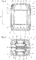
- FIG. 1 the embodiment of the canister 1 according to the invention can be seen in a view obliquely from above.
- the canister opening 13 is surrounded by a thread 19 onto which a lid for closing the canister opening 13 can be screwed.
- the arrangement of corresponding covers by means of clamps, screws or other types of connection on and on the canister opening 13 is known per se, and can be described in FIG The most varied of configurations can be implemented and need not be explained further here.
- the side walls 4 and the corner wall areas 5 arranged between two side walls 4 each adjoin below the canister top wall 3.
- the side walls 4 are flat in this embodiment.
- the side walls 4 and the corner wall areas 5 merge into the canister base 2, which in a view from below in Fig. 3 is shown.
- the canister bottom 2, the canister top wall 3, the four side walls 4 here and the four corner wall areas 5 arranged between them here together form the outer wall of the canister 1, which encloses the cavity.
- the named outer wall of the canister 1 is expediently formed in one piece.
- the entire outer wall can also be made from other materials or material compositions and / or from assembled individual parts.
- it is preferably an inherently rigid outer wall of the canister 1 that at least essentially maintains its shape.
- the canister 1 has a total of eight such reinforcing beads 6. Four of them lie with their end arc section 7 in the canister top wall 3. Opposite four reinforcement beads 6 with their end arc sections 7 in the canister bottom 2. Compared to the end arc sections 7, the reinforcement beads 6 according to the invention have a flat end 8 in the respective corner wall area 5.
- the reinforcing beads 6 therefore do not extend over the entire corner wall area 5 from the canister bottom 2 to the canister top wall 3.
- the ends 8 which taper off flatly are, as in FIG Fig. 1 easy to see, preferably parabolic, rounded.
- the depth 16, see Fig. 3 the In this exemplary embodiment, reinforcement beads 6 decrease continuously from the respective end curve section 7 to the flat end 8.
- the reinforcing bead can, for example, have the shape of a conical section in some areas, which is created by cutting a cone parallel or obliquely to its longitudinal axis.
- the reinforcing bead 6 is advantageously designed to be rounded everywhere.
- the boundary edges 9 delimiting the reinforcing bead 6 on opposite sides and tapering towards the flat end 8 of the reinforcing bead 6 are advantageously arranged at an angle 10 of 15 ° to 35 °, preferably 30 ° to 33 °.
- the radius 18 of the end arc section 7 is favorably in the range from R20 to R60, preferably from R30 to R35.
- Fig. 2 In the side view it can be seen particularly well that in preferred embodiments such as the one shown here, the reinforcing beads 6 are only arranged outside a central area 11 in which the side walls of the canister 1 are flat. In other words, the reinforcing beads 6, regardless of whether they start from the canister bottom 2 or from the canister top wall 3, do not extend into this central region 11. You thus end in the operating position of the canister according to Fig. 1 and 2 seen, either above or below, depending on whether they are arranged in the canister bottom 2 or in the canister top wall 3 with their end arc section 7.
- projections 14 are integrated into the canister top wall 3 in this exemplary embodiment.
- these are used in indentations 15 in its canister base 2, see Fig. 3 to intervene in a form-fitting manner in order to avoid a lateral displacement of the stacked canisters 1.
- these projections 14 and indentations 15 could also be shaped and arranged differently.
Landscapes
- Engineering & Computer Science (AREA)
- Mechanical Engineering (AREA)
- Ceramic Engineering (AREA)
- Stackable Containers (AREA)
- Purses, Travelling Bags, Baskets, Or Suitcases (AREA)
Description
- Die vorliegende Erfindung betrifft einen Kanister gemäß des Oberbegriffs des Patentanspruchs 1.
- Kanister dieser Art sind aus der
US 2010/0206759 A1 an sich bekannt. Sie werden zum Transport von Flüssigkeiten oder Schüttgut und zur Lagerung dieser Materialien verwendet. Im Sinne einer platzsparenden Aufbewahrung müssen diese Kanister häufig gestapelt werden. Dabei müssen die Kanister dann nicht nur ihr Eigengewicht und das Gewicht ihres Inhalts, sondern eben auch das Gewicht der darüber angeordneten Kanister samt Inhalt tragen. Um die Stapelfestigkeit, also die Fähigkeit von Kanistern, darüber gestapelte andere Kanister zu tragen, zu erhöhen, ist es z.B. aus derDE 20 2014 004 224 U1 bereits bekannt, Verstärkungssicken in den Eckwandbereichen anzuordnen. Diese Verstärkungssicken sind in den Hohlraum hinein gewölbt. - Bei solchem Stand der Technik werden diese Verstärkungssicken als durchgehende Rillen oder Nuten entlang mehr oder weniger des gesamten Eckwandbereichs von der Kanisterdeckwand bis zum Kanisterboden ausgeführt.
- Dies hat den Nachteil, dass dies zum einen relativ stark zu Lasten des nutzbaren Volumens des Hohlraums im Kanister geht und zum anderen oft optisch störend aussieht.
- Aufgabe der Erfindung ist es, einen Kanister der oben genannten Art dahingehend zu verbessern, der er einerseits sehr stapelfest ist, andererseits aber nicht die genannten Nachteile des Standes der Technik aufweist.
- Hierfür schlägt die Erfindung vor, dass die jeweilige der Verstärkungssicken im Kanisterboden oder in der Kanisterdeckwand in einem Endbogenabschnitt endet.
- Die jeweilige Verstärkungssicke erstreckt sich somit nicht über den gesamten Eckwandbereich des Kanisters von der Kanisterdeckwand bis zum Kanisterboden. Bei der Erfindung ist vielmehr vorgesehen, dass die jeweilige Verstärkungssicke zwar mit dem Endbogenabschnitt im Kanisterboden oder in der Kanisterdeckwand beginnt, aber dann innerhalb des Eckwandbereichs ein flach auslaufendes Ende aufweist und sich somit nicht über den gesamten Eckwandbereich von der Kanisterdeckwand bis zum Kanisterboden erstreckt. Hierdurch wird einerseits eine optisch ansprechende Form der Verstärkungssicke geschaffen, andererseits wird durch die erfindungsgemäßen Verstärkungssicken das Volumen des Hohlraums des Kanisters wesentlich weniger herabgesetzt als beim Stand der Technik.
- In der Kanisterdeckwand kann, wie an sich bekannt, ein Tragegriff des Kanisters angeordnet bzw. einstückig angeformt sein. Weiters befindet sich in der Kanisterdeckwand günstigerweise eine Kanisteröffnung zum Befüllen und Entleeren des Kanisters. Diese Kanisteröffnung ist in bevorzugten Ausgestaltungsformen der Erfindung die einzige Öffnung des Kanisters. Ansonsten umschließen der Kanisterboden, die Kanisterdeckwand, die Seitenwände und die Eckwandbereiche den Hohlraum des Kanisters günstigerweise vollständig. Vorzugsweise ist die Kanisteröffnung mittels eines Deckels verschließbar, vorzugsweise mehrfach öffenund verschließbar. Es kann sich z.B. um einen aufschraubbaren, einrastbaren klemmend haltenden oder sonstigen Deckel handeln, mit dem die Kanisteröffnung verschlossen werden kann.
- Die Außenwandung des Kanisters kann aus unterschiedlichen Materialien hergestellt sein. Besonders bevorzugt ist die Außenwandung aus Kunststoff ausgeführt. Es kann sich z.B. um spritzgegossene oder in einem Blasverfahren hergestellte Kanister handeln. Damit die aufeinandergestapelten Kanister nicht relativ zueinander verschoben werden können, sehen bevorzugte Varianten der Erfindung vor, dass in der Kanisterdeckwand und/oder im Kanisterboden Vorsprünge und/oder Einbuchtungen zur Vermeidung des seitlichen Verschiebens von aufeinander gestapelten Kanistern angeordnet sind. So können z.B. die Vorsprünge in der Kanisterdeckwand des einen Kanisters in entsprechende bzw. korrespondierende Einbuchtungen im Kanisterboden des darüber angeordneten Kanisters eingreifen, um so ein unbeabsichtigtes Verschieben der aufeinander gestaptelten Kanister zu vermeiden. Natürlich können auch entsprechende Einbuchtungen in der Kanisterdeckwand und Vorsprünge in dem Kanisterboden angeordnet sein.
- Das flach auslaufende Ende der jeweiligen Verstärkungssicke ist bevorzugt gerundet ausgebildet. Besonders bevorzugt handelt es sich um eine parabelartige Ausbildung der Rundung. Parabelartig ist dabei nicht nur im streng mathematischen Sinne, sondern allgemein als parabelförmig aussehend zu verstehen.
- Die Tiefe der Verstärkungssicke nimmt in bevorzugten Varianten vom Endbogenabschnitt zum flach auslaufenden Ende hin ab. Vorzugsweise nimmt die Tiefe der Verstärkungssicke in diese Richtung kontinuierlich ab.
- Die Verstärkungssicke kann z.B. die Form eines parallel oder schräg zur Längsachse eines Kegels geschnittenen Kegelschnitts aufweisen. Der Endbogenabschnitt im Kanisterboden oder in der Kanisterdeckwand weist in bevorzugten Ausgestaltungsformen einen Radius im Bereich von R20 bis R60, vorzugsweise von R30 bis R35, auf. Besonders bevorzugt ist die Verstärkungssicke überall gerundet ausgebildet.
- Bevorzugte Varianten der Erfindung sehen vor, dass die Verstärkungssicke im Bereich des Endbogenabschnitts eine Tiefe im Bereich von 3 mm bis 15 mm, vorzugsweise von 5 mm bis 10 mm, aufweist und/oder dass die Verstärkungssicke zwischen dem Endbogenabschnitt und dem flach auslaufenden Ende eine Längserstreckung im Bereich von 50 mm bis 120 mm, vorzugsweise von 70 mm bis 90 mm, aufweist.
- Die einander gegenüberliegenden Begrenzungskanten der Verstärkungssicke laufen günstigerweise zum flach auslaufenden Ende hin aufeinander zu. Bevorzugt ist vorgesehen, dass die einander gegenüberliegenden Begrenzungskanten der Verstärkungssicke, welche auf das flach auslaufende Ende der Verstärkungssicke zulaufen, innerhalb eines Winkels von 15° bis 35°, vorzugsweise von 30° bis 33° liegen. Im Zweifel werden diese Winkel in einer Projektion normal auf den Endwandbereich im Bereich der Verstärkungssicke gemessen.
- Bevorzugte Varianten der Erfindung sehen vor, dass die Seitenwände des Kanisters in einem mittleren Bereich des Kanisters eben ausgebildet sind und die Verstärkungssicken nur außerhalb, also entweder oberhalb oder unterhalb, des mittleren Bereichs angeordnet sind. In anderen Worten reichen die Verstärkungssicken ausgehend vom Kanisterboden oder ausgehend von der Kanisterdeckwand also nicht in diesen mittleren Bereich des Kanisters hinein.
- Grundsätzlich ist darauf hinzuweisen, dass die Endbogenabschnitte der Verstärkungssicke immer entweder im Kanisterboden oder in der Kanisterdeckwand angeordnet sind. Im Fall von vier Seitenwänden und vier dazwischen angeordneten Eckwandbereichen hat ein Kanister dann in bevorzugten Ausgestaltungsformen vier vom Kanisterboden sich nach oben erstreckende Verstärkungssicken und gegenüberliegend vier von der Kanisterdeckwand sich nach unten erstreckende Verstärkungssicken. Generell ist darauf hinzuweisen, dass die Eckwandbereiche Übergangsbereiche zwischen zwei in der Regel in einem 90° Winkel zueinander angeordneten Seitenwänden des Kanisters bilden. Die Eckwandbereiche können in einem Horizontalschnitt gesehen vollständig gebogen, aber auch bereichsweise gerade ausgebildet sein. Sie bilden letztendlich den Übergang in Umfangsrichtung von einer Seitenwand zur nächsten Seitenwand. Die Seitenwände können in besagtem Horizontalschnitt gesehen, auf einem Rechteck liegen, wobei die Eckwandbereiche dann eben den meist bereichsweise abgerundeten Übergang zwischen zwei orthogonal zueinander angeordneten Seitenwänden bilden. Man könnte in solchen Fällen auch davon sprechen, dass der Kanister abgesehen von der Ausbildung exakter Ecken eine rechteckförmige oder quadratische Grundform aufweist.
- In den Figuren ist eine bevorzugte Ausgestaltungsform eines erfindungsgemäßen Kanisters gezeigt. In der Figurenbeschreibung werden nachfolgend anhand dieses Beispiels noch einmal bevorzugte Ausgestaltungsformen der Erfindung erläutert, wobei diese nicht unbedingt zwingend alle in Kombination miteinander realisiert werden müssen, sondern auch einzeln realisiert werden können. Es zeigen:
- Fig. 1
- eine perspektivische Darstellung des Ausführungsbeispiels des erfindungsgemäßen Kanisters von schräg oben;
- Fig. 2
- eine Seitenansicht dieses Ausführungsbeispiels und
- Fig. 3
- eine Ansicht von unten auf den Kanisterboden des Ausführungsbeispiels aus
Fig. 1 und2 . - In der perspektivischen Darstellung gemäß
Fig. 1 ist das Ausführungsbeispiel des erfindungsgemäßen Kanisters 1 in einer Ansicht von schräg oben zu sehen. Gut erkennbar ist die Kanisterdeckwand 3 mit dem Tragegriff 12 und der Kanisteröffnung 13, durch die hindurch der sich innen im Kanister 1 befindende Hohlraum befüllt und entleert werden kann. Die Kanisteröffnung 13 ist im gezeigten Ausführungsbeispiel von einem Gewinde 19 umgeben, auf das ein Deckel zum Verschließen der Kanisteröffnung 13 aufgeschraubt werden kann. Die Anordnung von entsprechenden Deckeln durch Klemmen, Schrauben oder andere Verbindungsarten auf und an der Kanisteröffnung 13 ist an sich bekannt, kann in unterschiedlichsten Ausgestaltungsformen realisiert werden und muss hier nicht weiter erläutert werden. - Unterhalb der Kanisterdeckwand 3 schließen die Seitenwände 4 und die zwischen jeweils zwei Seitenwänden 4 angeordneten Eckwandbereiche 5 an. In ihrem mittleren Bereich 11, siehe
Fig. 2 , sind die Seitenwände 4 in diesem Ausführungsbeispiel eben ausgebildet. Am unteren Ende des Kanisters 1 gehen die Seitenwände 4 und die Eckwandbereiche 5 in den Kanisterboden 2 über, welcher in einer Ansicht von unten inFig. 3 dargestellt ist. Der Kanisterboden 2, die Kanisterdeckwand 3, die hier vier Seitenwände 4 und die hier vier dazwischen angeordneten Eckwandbereiche 5 bilden zusammen die Außenwandung des Kanisters 1, welche den Hohlraum umschließt. In diesem Ausführungsbeispiel, wie auch in anderen bevorzugten Ausgestaltungsformen umschließt diese Außenwandung abgesehen von der Kanisteröffnung 13 den Hohlraum des Kanisters 1 vollständig. Günstigerweise ist die genannte Außenwandung des Kanisters 1 einstückig ausgebildet. Es kann sich z.B. um einen einstückigen Kunststoffkörper handeln. Natürlich kann die gesamte Außenwandung auch aus anderen Materialien oder Materialzusammensetzungen und/oder aus zusammengefügten Einzelteilen realisiert werden. Bevorzugt handelt es sich jedenfalls um eine in sich steife, ihre Form zumindest im Wesentlichen selbst erhaltende Außenwandung des Kanisters 1. Um die Stapelbarkeit und damit die Formstabilität des Kanisters 1 zu erhöhen, sind in den Eckwandbereichen 5 in den Hohlraum hineingewölbte Verstärkungssicken 6 ausgebildet. Im gezeigten Ausführungsbeispiel weist der Kanister 1 insgesamt acht solcher Verstärkungssicken 6 auf. Vier davon liegen mit ihrem Endbogenabschnitt 7 in der Kanisterdeckwand 3. Gegenüberliegend liegen wiederum vier Verstärkungssicken 6 mit ihren Endbogenabschnitten 7 im Kanisterboden 2. Gegenüber den Endbogenabschnitten 7 weisen die Verstärkungssicken 6 erfindungsgemäß im jeweiligen Eckwandbereich 5 ein flach auslaufendes Ende 8 auf. Anders als beim Stand der Technik erstrecken sich die Verstärkungssicken 6 somit nicht über den gesamten Eckwandbereich 5 vom Kanisterboden 2 bis zur Kanisterdeckwand 3. Die flach auslaufenden Enden 8 sind, wie inFig. 1 gut zu sehen, vorzugsweise parabelartig, gerundet ausgebildet. Die Tiefe 16, sieheFig. 3 , der Verstärkungssicken 6 nimmt in diesem Ausführungsbeispiel kontinuierlich vom jeweiligen Endbogenabschnitt 7 zum flach auslaufenden Ende 8 hin ab. Die Verstärkungssicke kann, wie hier gezeigt, z.B. bereichsweise die Form eines Kegelschnitts aufweisen, welcher durch das Schneiden eines Kegels parallel oder schräg zu seiner Längsachse entsteht. Die Verstärkungssicke 6 ist günstigerweise überall gerundet ausgebildet. Die die Verstärkungssicke 6 auf einander gegenüberliegenden Seiten begrenzenden Begrenzungskanten 9, welche auf das flach auslaufende Ende 8 der Verstärkungssicke 6 zulaufen, sind günstigerweise in einem Winkel 10 von 15° bis 35°, vorzugsweise von 30° bis 33° angeordnet. Für die Tiefe 16 und die Längserstreckung 17 der jeweiligen Verstärkungssicke gelten günstigerweise die eingangs bereits genannten Werte. Der Radius 18 des Endbogenabschnitts 7 liegt günstigerweise im Bereich von R20 bis R60, vorzugsweise von R30 bis R35. - In
Fig. 2 in der Seitenansicht ist besonders gut zu sehen, dass in bevorzugten Ausgestaltungsformen wie der hier gezeigten, die Verstärkungssicken 6 nur außerhalb eines mittleren Bereichs 11 angeordnet sind, in welchem die Seitenwände des Kanisters 1 eben ausgebildet sind. In anderen Worten erstrecken sich die Verstärkungssicken 6, egal ob sie vom Kanisterboden 2 oder von der Kanisterdeckwand 3 ausgehen, nicht in diesen mittleren Bereich 11 hinein. Sie enden somit, in der Betriebsstellung des Kanisters gemäßFig.1 und2 gesehen, entweder oberhalb oder unterhalb, je nachdem, ob sie im Kanisterboden 2 oder in der Kanisterdeckwand 3 mit ihrem Endbogenabschnitt 7 angeordnet sind. - In
Fig. 1 ist auch gut zu sehen, dass in diesem Ausführungsbeispiel Vorsprünge 14 in die Kanisterdeckwand 3 integriert sind. Diese dienen dazu, bei einem darüber gestapelten Kanister 1 dieser Art in Einbuchtungen 15 i n dessen Kanisterboden 2, sieheFig. 3 , formschlüssig einzugreifen, um so ein seitliches Verschieben der aufeinandergestapelten Kanister 1 zu vermeiden. Natürlich könnten diese Vorsprünge 14 und Einbuchtungen 15 auch anders ausgeformt und angeordnet sein. -
- 1
- Kanister
- 2
- Kanisterboden
- 3
- Kanisterdeckwand
- 4
- Seitenwand
- 5
- Eckwandbereich
- 6
- Verstärkungssicke
- 7
- Endbogenabschnitt
- 8
- flach auslaufendes Ende
- 9
- Begrenzungskante
- 10
- Winkel
- 11
- mittlerer Bereich
- 12
- Tragegriff
- 13
- Kanisteröffnung
- 14
- Vorsprung
- 15
- Einbuchtung
- 16
- Tiefe
- 17
- Längserstreckung
- 18
- Radius
- 19
- Gewinde
Claims (10)
- Kanister (1) zur Aufnahme von Flüssigkeiten und/oder Schüttgut in einem Hohlraum des Kanisters (1), wobei der Kanister (1) einen Kanisterboden (2) zum Abstellen des Kanisters (1) auf einem Untergrund und eine, dem Kanisterboden (2) gegenüberliegende Kanisterdeckwand (3) und zumindest vier Seitenwände (4) und zumindest vier Eckwandbereiche (5) aufweist, wobei der Kanisterboden (2) über die Seitenwände (4) und über die Eckwandbereiche (5) fix mit der Kanisterdeckwand (3) verbunden ist und zwischen jeweils zwei der Seitenwände (4) jeweils einer der Eckwandbereiche (5) ausgebildet ist und der Kanisterboden (2) und die Kanisterdeckwand (3) und die Seitenwände (4) und die Eckwandbereiche (5) gemeinsam eine, den Hohlraum des Kanisters (1) umschließende Außenwandung des Kanisters (1) ausbilden und in den Eckwandbereichen (5) in den Hohlraum hinein gewölbte Verstärkungssicken (6) ausgebildet sind, wobei eine jeweilige der Verstärkungssicken (6) in dem jeweiligen Eckwandbereich (5) ein flach auslaufendes Ende (8) aufweist, dadurch gekennzeichnet, dass die jeweilige der Verstärkungssicken (6) im Kanisterboden (2) oder in der Kanisterdeckwand (3) in einem Endbogenabschnitt (7) endet.
- Kanister (1) nach Anspruch 1, dadurch gekennzeichnet, dass das flach auslaufende Ende (8), vorzugsweise parabelartig, gerundet ausgebildet ist.
- Kanister (1) nach Anspruch 1 oder 2, dadurch gekennzeichnet, dass die Tiefe (16) der Verstärkungssicke (6) vom Endbogenabschnitt (7) zum flach auslaufenden Ende (8) hin, vorzugsweise kontinuierlich, abnimmt.
- Kanister (1) nach einem der Ansprüche 1 bis 3, dadurch gekennzeichnet, dass die Verstärkungssicke (6) zumindest bereichsweise die Form eines, parallel oder schräg zur Längsachse eines Kegels geschnittenen Kegelschnitts aufweist.
- Kanister (1) nach einem der Ansprüche 1 bis 4, dadurch gekennzeichnet, dass der Endbogenabschnitt (7) einen Radius (18) im Bereich von R20 bis R60, vorzugsweise von R30 bis R35, aufweist.
- Kanister (1) nach einem der Ansprüche 1 bis 5, dadurch gekennzeichnet, dass die Verstärkungssicke (6) überall gerundet ausgebildet ist.
- Kanister (1) nach einem der Ansprüche 1 bis 6, dadurch gekennzeichnet, dass die Verstärkungssicke (6) im Bereich des Endbogenabschnitts (7) eine Tiefe (16) im Bereich von 3 mm bis 15 mm, vorzugsweise von 5 mm bis 10 mm, aufweist und/oder dass die Verstärkungssicke (6) zwischen dem Endbogenabschnitt (7) und dem flach auslaufenden Ende (8) eine Längserstreckung (17) im Bereich von 50 mm bis 120 mm, vorzugsweise von 70 mm bis 90 mm, aufweist.
- Kanister (1) nach einem der Ansprüche 1 bis 7, dadurch gekennzeichnet, dass einander gegenüberliegende Begrenzungskanten (9) der Verstärkungssicke (6), welche auf das flach auslaufende Ende (8) der Verstärkungssicke (6) zulaufen, innerhalb eines Winkels (10) von 15° bis 35°, vorzugsweise von 30° bis 33°, liegen.
- Kanister (1) nach einem der Ansprüche 1 bis 8, dadurch gekennzeichnet, dass die Seitenwände (4) des Kanisters (1) in einem mittleren Bereich (11) des Kanisters (1) eben ausgebildet sind und die Verstärkungssicken (6) nur außerhalb dieses mittleren Bereichs (11) angeordnet sind.
- Kanister (1) nach einem der Ansprüche 1 bis 9, dadurch gekennzeichnet, dass in der Kanisterdeckwand (3) ein Tragegriff (12) und/oder eine, vorzugsweise mittels eines Deckels verschließbare, Kanisteröffnung (13) zum Befüllen und Entleeren des Kanisters (1) angeordnet ist bzw. sind, und/oder dass im Kanisterboden (2) und/oder in der Kanisterdeckwand (3) Vorsprünge (14) und/oder Einbuchtungen (15) zur Vermeidung des seitlichen Verschiebens von aufeinander gestapelten Kanistern (1) angeordnet sind.
Applications Claiming Priority (1)
| Application Number | Priority Date | Filing Date | Title |
|---|---|---|---|
| ATGM158/2018U AT16460U1 (de) | 2018-08-03 | 2018-08-03 | Kanister |
Publications (2)
| Publication Number | Publication Date |
|---|---|
| EP3608247A1 EP3608247A1 (de) | 2020-02-12 |
| EP3608247B1 true EP3608247B1 (de) | 2021-08-04 |
Family
ID=68159864
Family Applications (1)
| Application Number | Title | Priority Date | Filing Date |
|---|---|---|---|
| EP19182481.2A Active EP3608247B1 (de) | 2018-08-03 | 2019-06-26 | Kanister |
Country Status (2)
| Country | Link |
|---|---|
| EP (1) | EP3608247B1 (de) |
| AT (1) | AT16460U1 (de) |
Families Citing this family (1)
| Publication number | Priority date | Publication date | Assignee | Title |
|---|---|---|---|---|
| US20250026553A1 (en) * | 2023-07-18 | 2025-01-23 | Ring Container Technologies, Llc | Container and packaging system |
Family Cites Families (7)
| Publication number | Priority date | Publication date | Assignee | Title |
|---|---|---|---|---|
| US5114028A (en) * | 1990-06-20 | 1992-05-19 | Ring Can Corporation | Container with integral handle structure |
| US5340000A (en) * | 1993-07-13 | 1994-08-23 | Ring Can Corporation | Vented plastic bottle |
| CA2392564C (en) * | 2002-01-17 | 2006-01-17 | Plastipak Packaging, Inc. | Plastic container |
| US9896233B2 (en) * | 2002-12-05 | 2018-02-20 | Graham Packaging Company, L.P. | Rectangular container having a vertically extending groove |
| US7726503B2 (en) * | 2006-09-25 | 2010-06-01 | Ring Container Technologies | Ergonomic plastic container and package system |
| US8235214B2 (en) * | 2007-03-05 | 2012-08-07 | Dean Intellectual Property Services Ii, Inc. | Stackable liquid container with tunnel-shaped base |
| DE202014004224U1 (de) * | 2014-03-27 | 2015-07-17 | Stelioplast Roland Stengel Kunststoffverarbeitung Gmbh | Stapelbarer Flüssigkeitsbehälter |
-
2018
- 2018-08-03 AT ATGM158/2018U patent/AT16460U1/de unknown
-
2019
- 2019-06-26 EP EP19182481.2A patent/EP3608247B1/de active Active
Also Published As
| Publication number | Publication date |
|---|---|
| AT16460U1 (de) | 2019-10-15 |
| EP3608247A1 (de) | 2020-02-12 |
Similar Documents
| Publication | Publication Date | Title |
|---|---|---|
| EP2163483B1 (de) | Kunststoffbehältnis | |
| DE60101556T2 (de) | Durch umlaufende nuten verstärkter kunststoffbehälter mit nicht-zylindrischem körper | |
| EP0257281B1 (de) | Flüssigkeitspackung mit Griff | |
| DE10259126B4 (de) | Kunststofftonne | |
| DE2711591A1 (de) | Behaelter fuer die abgabe von fluessigkeiten | |
| EP4045429B1 (de) | Palettencontainer | |
| EP2644530A1 (de) | Einschweißausgießer | |
| DE202008012290U1 (de) | Kunststoffbehältnis | |
| DE102007044279B4 (de) | Anordnung zum Lagern und/oder Transportieren | |
| EP3608247A1 (de) | Kanister | |
| DE3621742C2 (de) | ||
| DE8707228U1 (de) | Wandverstärkter Stapelkasten | |
| EP2918508A1 (de) | Behälter, insbesondere Palettenbehälter | |
| EP0453775A2 (de) | Verpackung | |
| DE202014105307U1 (de) | Behälter für Lebensmittel | |
| EP0254968B1 (de) | Flüssigkeitspackung mit tiefgezogenem Deckel | |
| DE1486673C (de) | ||
| EP1354825B1 (de) | Müllbehälter mit verstärkter Zapfen-Einheit | |
| EP0699160A1 (de) | Stapelbarer ineinandersetzbarer behälter | |
| DE4402576C2 (de) | Flexibler Transportbehälter | |
| DE202014004224U1 (de) | Stapelbarer Flüssigkeitsbehälter | |
| EP0439836B1 (de) | Zusammenfaltbare Vorratsflasche | |
| WO2016131523A1 (de) | Kasten aus kunststoff, insbesondere flaschenkasten | |
| DE8913144U1 (de) | Behälter für flüssiges Füllgut | |
| DE1486673B2 (de) | Transportkasten |
Legal Events
| Date | Code | Title | Description |
|---|---|---|---|
| PUAI | Public reference made under article 153(3) epc to a published international application that has entered the european phase |
Free format text: ORIGINAL CODE: 0009012 |
|
| STAA | Information on the status of an ep patent application or granted ep patent |
Free format text: STATUS: THE APPLICATION HAS BEEN PUBLISHED |
|
| AK | Designated contracting states |
Kind code of ref document: A1 Designated state(s): AL AT BE BG CH CY CZ DE DK EE ES FI FR GB GR HR HU IE IS IT LI LT LU LV MC MK MT NL NO PL PT RO RS SE SI SK SM TR |
|
| AX | Request for extension of the european patent |
Extension state: BA ME |
|
| STAA | Information on the status of an ep patent application or granted ep patent |
Free format text: STATUS: REQUEST FOR EXAMINATION WAS MADE |
|
| 17P | Request for examination filed |
Effective date: 20200702 |
|
| RBV | Designated contracting states (corrected) |
Designated state(s): AL AT BE BG CH CY CZ DE DK EE ES FI FR GB GR HR HU IE IS IT LI LT LU LV MC MK MT NL NO PL PT RO RS SE SI SK SM TR |
|
| REG | Reference to a national code |
Ref country code: DE Ref legal event code: R079 Ref document number: 502019001948 Country of ref document: DE Free format text: PREVIOUS MAIN CLASS: B65D0021020000 Ipc: B65D0021000000 |
|
| GRAP | Despatch of communication of intention to grant a patent |
Free format text: ORIGINAL CODE: EPIDOSNIGR1 |
|
| STAA | Information on the status of an ep patent application or granted ep patent |
Free format text: STATUS: GRANT OF PATENT IS INTENDED |
|
| RIC1 | Information provided on ipc code assigned before grant |
Ipc: B65D 21/00 20060101AFI20210308BHEP Ipc: B65D 1/20 20060101ALI20210308BHEP Ipc: B65D 21/02 20060101ALI20210308BHEP Ipc: B65D 25/28 20060101ALI20210308BHEP |
|
| INTG | Intention to grant announced |
Effective date: 20210324 |
|
| GRAS | Grant fee paid |
Free format text: ORIGINAL CODE: EPIDOSNIGR3 |
|
| GRAA | (expected) grant |
Free format text: ORIGINAL CODE: 0009210 |
|
| STAA | Information on the status of an ep patent application or granted ep patent |
Free format text: STATUS: THE PATENT HAS BEEN GRANTED |
|
| AK | Designated contracting states |
Kind code of ref document: B1 Designated state(s): AL AT BE BG CH CY CZ DE DK EE ES FI FR GB GR HR HU IE IS IT LI LT LU LV MC MK MT NL NO PL PT RO RS SE SI SK SM TR |
|
| REG | Reference to a national code |
Ref country code: GB Ref legal event code: FG4D Free format text: NOT ENGLISH |
|
| REG | Reference to a national code |
Ref country code: AT Ref legal event code: REF Ref document number: 1416777 Country of ref document: AT Kind code of ref document: T Effective date: 20210815 |
|
| REG | Reference to a national code |
Ref country code: CH Ref legal event code: EP |
|
| REG | Reference to a national code |
Ref country code: DE Ref legal event code: R096 Ref document number: 502019001948 Country of ref document: DE |
|
| REG | Reference to a national code |
Ref country code: IE Ref legal event code: FG4D Free format text: LANGUAGE OF EP DOCUMENT: GERMAN |
|
| REG | Reference to a national code |
Ref country code: LT Ref legal event code: MG9D |
|
| REG | Reference to a national code |
Ref country code: NL Ref legal event code: MP Effective date: 20210804 |
|
| PG25 | Lapsed in a contracting state [announced via postgrant information from national office to epo] |
Ref country code: SE Free format text: LAPSE BECAUSE OF FAILURE TO SUBMIT A TRANSLATION OF THE DESCRIPTION OR TO PAY THE FEE WITHIN THE PRESCRIBED TIME-LIMIT Effective date: 20210804 Ref country code: RS Free format text: LAPSE BECAUSE OF FAILURE TO SUBMIT A TRANSLATION OF THE DESCRIPTION OR TO PAY THE FEE WITHIN THE PRESCRIBED TIME-LIMIT Effective date: 20210804 Ref country code: ES Free format text: LAPSE BECAUSE OF FAILURE TO SUBMIT A TRANSLATION OF THE DESCRIPTION OR TO PAY THE FEE WITHIN THE PRESCRIBED TIME-LIMIT Effective date: 20210804 Ref country code: FI Free format text: LAPSE BECAUSE OF FAILURE TO SUBMIT A TRANSLATION OF THE DESCRIPTION OR TO PAY THE FEE WITHIN THE PRESCRIBED TIME-LIMIT Effective date: 20210804 Ref country code: HR Free format text: LAPSE BECAUSE OF FAILURE TO SUBMIT A TRANSLATION OF THE DESCRIPTION OR TO PAY THE FEE WITHIN THE PRESCRIBED TIME-LIMIT Effective date: 20210804 Ref country code: PT Free format text: LAPSE BECAUSE OF FAILURE TO SUBMIT A TRANSLATION OF THE DESCRIPTION OR TO PAY THE FEE WITHIN THE PRESCRIBED TIME-LIMIT Effective date: 20211206 Ref country code: NO Free format text: LAPSE BECAUSE OF FAILURE TO SUBMIT A TRANSLATION OF THE DESCRIPTION OR TO PAY THE FEE WITHIN THE PRESCRIBED TIME-LIMIT Effective date: 20211104 Ref country code: LT Free format text: LAPSE BECAUSE OF FAILURE TO SUBMIT A TRANSLATION OF THE DESCRIPTION OR TO PAY THE FEE WITHIN THE PRESCRIBED TIME-LIMIT Effective date: 20210804 Ref country code: BG Free format text: LAPSE BECAUSE OF FAILURE TO SUBMIT A TRANSLATION OF THE DESCRIPTION OR TO PAY THE FEE WITHIN THE PRESCRIBED TIME-LIMIT Effective date: 20211104 |
|
| PG25 | Lapsed in a contracting state [announced via postgrant information from national office to epo] |
Ref country code: PL Free format text: LAPSE BECAUSE OF FAILURE TO SUBMIT A TRANSLATION OF THE DESCRIPTION OR TO PAY THE FEE WITHIN THE PRESCRIBED TIME-LIMIT Effective date: 20210804 Ref country code: LV Free format text: LAPSE BECAUSE OF FAILURE TO SUBMIT A TRANSLATION OF THE DESCRIPTION OR TO PAY THE FEE WITHIN THE PRESCRIBED TIME-LIMIT Effective date: 20210804 Ref country code: GR Free format text: LAPSE BECAUSE OF FAILURE TO SUBMIT A TRANSLATION OF THE DESCRIPTION OR TO PAY THE FEE WITHIN THE PRESCRIBED TIME-LIMIT Effective date: 20211105 |
|
| PG25 | Lapsed in a contracting state [announced via postgrant information from national office to epo] |
Ref country code: NL Free format text: LAPSE BECAUSE OF FAILURE TO SUBMIT A TRANSLATION OF THE DESCRIPTION OR TO PAY THE FEE WITHIN THE PRESCRIBED TIME-LIMIT Effective date: 20210804 |
|
| PG25 | Lapsed in a contracting state [announced via postgrant information from national office to epo] |
Ref country code: DK Free format text: LAPSE BECAUSE OF FAILURE TO SUBMIT A TRANSLATION OF THE DESCRIPTION OR TO PAY THE FEE WITHIN THE PRESCRIBED TIME-LIMIT Effective date: 20210804 |
|
| REG | Reference to a national code |
Ref country code: DE Ref legal event code: R097 Ref document number: 502019001948 Country of ref document: DE |
|
| PG25 | Lapsed in a contracting state [announced via postgrant information from national office to epo] |
Ref country code: SM Free format text: LAPSE BECAUSE OF FAILURE TO SUBMIT A TRANSLATION OF THE DESCRIPTION OR TO PAY THE FEE WITHIN THE PRESCRIBED TIME-LIMIT Effective date: 20210804 Ref country code: SK Free format text: LAPSE BECAUSE OF FAILURE TO SUBMIT A TRANSLATION OF THE DESCRIPTION OR TO PAY THE FEE WITHIN THE PRESCRIBED TIME-LIMIT Effective date: 20210804 Ref country code: RO Free format text: LAPSE BECAUSE OF FAILURE TO SUBMIT A TRANSLATION OF THE DESCRIPTION OR TO PAY THE FEE WITHIN THE PRESCRIBED TIME-LIMIT Effective date: 20210804 Ref country code: EE Free format text: LAPSE BECAUSE OF FAILURE TO SUBMIT A TRANSLATION OF THE DESCRIPTION OR TO PAY THE FEE WITHIN THE PRESCRIBED TIME-LIMIT Effective date: 20210804 Ref country code: CZ Free format text: LAPSE BECAUSE OF FAILURE TO SUBMIT A TRANSLATION OF THE DESCRIPTION OR TO PAY THE FEE WITHIN THE PRESCRIBED TIME-LIMIT Effective date: 20210804 Ref country code: AL Free format text: LAPSE BECAUSE OF FAILURE TO SUBMIT A TRANSLATION OF THE DESCRIPTION OR TO PAY THE FEE WITHIN THE PRESCRIBED TIME-LIMIT Effective date: 20210804 |
|
| PLBE | No opposition filed within time limit |
Free format text: ORIGINAL CODE: 0009261 |
|
| STAA | Information on the status of an ep patent application or granted ep patent |
Free format text: STATUS: NO OPPOSITION FILED WITHIN TIME LIMIT |
|
| 26N | No opposition filed |
Effective date: 20220506 |
|
| PG25 | Lapsed in a contracting state [announced via postgrant information from national office to epo] |
Ref country code: SI Free format text: LAPSE BECAUSE OF FAILURE TO SUBMIT A TRANSLATION OF THE DESCRIPTION OR TO PAY THE FEE WITHIN THE PRESCRIBED TIME-LIMIT Effective date: 20210804 |
|
| PG25 | Lapsed in a contracting state [announced via postgrant information from national office to epo] |
Ref country code: MC Free format text: LAPSE BECAUSE OF FAILURE TO SUBMIT A TRANSLATION OF THE DESCRIPTION OR TO PAY THE FEE WITHIN THE PRESCRIBED TIME-LIMIT Effective date: 20210804 |
|
| REG | Reference to a national code |
Ref country code: BE Ref legal event code: MM Effective date: 20220630 |
|
| PG25 | Lapsed in a contracting state [announced via postgrant information from national office to epo] |
Ref country code: LU Free format text: LAPSE BECAUSE OF NON-PAYMENT OF DUE FEES Effective date: 20220626 Ref country code: IE Free format text: LAPSE BECAUSE OF NON-PAYMENT OF DUE FEES Effective date: 20220626 |
|
| PG25 | Lapsed in a contracting state [announced via postgrant information from national office to epo] |
Ref country code: BE Free format text: LAPSE BECAUSE OF NON-PAYMENT OF DUE FEES Effective date: 20220630 |
|
| GBPC | Gb: european patent ceased through non-payment of renewal fee |
Effective date: 20230626 |
|
| PG25 | Lapsed in a contracting state [announced via postgrant information from national office to epo] |
Ref country code: MK Free format text: LAPSE BECAUSE OF FAILURE TO SUBMIT A TRANSLATION OF THE DESCRIPTION OR TO PAY THE FEE WITHIN THE PRESCRIBED TIME-LIMIT Effective date: 20210804 Ref country code: CY Free format text: LAPSE BECAUSE OF FAILURE TO SUBMIT A TRANSLATION OF THE DESCRIPTION OR TO PAY THE FEE WITHIN THE PRESCRIBED TIME-LIMIT Effective date: 20210804 Ref country code: GB Free format text: LAPSE BECAUSE OF NON-PAYMENT OF DUE FEES Effective date: 20230626 |
|
| PG25 | Lapsed in a contracting state [announced via postgrant information from national office to epo] |
Ref country code: HU Free format text: LAPSE BECAUSE OF FAILURE TO SUBMIT A TRANSLATION OF THE DESCRIPTION OR TO PAY THE FEE WITHIN THE PRESCRIBED TIME-LIMIT; INVALID AB INITIO Effective date: 20190626 |
|
| PG25 | Lapsed in a contracting state [announced via postgrant information from national office to epo] |
Ref country code: TR Free format text: LAPSE BECAUSE OF FAILURE TO SUBMIT A TRANSLATION OF THE DESCRIPTION OR TO PAY THE FEE WITHIN THE PRESCRIBED TIME-LIMIT Effective date: 20210804 |
|
| PG25 | Lapsed in a contracting state [announced via postgrant information from national office to epo] |
Ref country code: MT Free format text: LAPSE BECAUSE OF FAILURE TO SUBMIT A TRANSLATION OF THE DESCRIPTION OR TO PAY THE FEE WITHIN THE PRESCRIBED TIME-LIMIT Effective date: 20210804 |
|
| PGFP | Annual fee paid to national office [announced via postgrant information from national office to epo] |
Ref country code: DE Payment date: 20250626 Year of fee payment: 7 |
|
| PGFP | Annual fee paid to national office [announced via postgrant information from national office to epo] |
Ref country code: FR Payment date: 20250624 Year of fee payment: 7 |
|
| PGFP | Annual fee paid to national office [announced via postgrant information from national office to epo] |
Ref country code: AT Payment date: 20250612 Year of fee payment: 7 |
|
| PGFP | Annual fee paid to national office [announced via postgrant information from national office to epo] |
Ref country code: IT Payment date: 20250623 Year of fee payment: 7 |
|
| PGFP | Annual fee paid to national office [announced via postgrant information from national office to epo] |
Ref country code: CH Payment date: 20250701 Year of fee payment: 7 |