EP3608173A1 - Aussenspiegelvorrichtung für ein kraftfahrzeug, kraftfahrzeug - Google Patents
Aussenspiegelvorrichtung für ein kraftfahrzeug, kraftfahrzeug Download PDFInfo
- Publication number
- EP3608173A1 EP3608173A1 EP19190411.9A EP19190411A EP3608173A1 EP 3608173 A1 EP3608173 A1 EP 3608173A1 EP 19190411 A EP19190411 A EP 19190411A EP 3608173 A1 EP3608173 A1 EP 3608173A1
- Authority
- EP
- European Patent Office
- Prior art keywords
- mirror
- flow guide
- mirror device
- mirror base
- base
- Prior art date
- Legal status (The legal status is an assumption and is not a legal conclusion. Google has not performed a legal analysis and makes no representation as to the accuracy of the status listed.)
- Granted
Links
Images
Classifications
-
- B—PERFORMING OPERATIONS; TRANSPORTING
- B60—VEHICLES IN GENERAL
- B60R—VEHICLES, VEHICLE FITTINGS, OR VEHICLE PARTS, NOT OTHERWISE PROVIDED FOR
- B60R1/00—Optical viewing arrangements; Real-time viewing arrangements for drivers or passengers using optical image capturing systems, e.g. cameras or video systems specially adapted for use in or on vehicles
- B60R1/02—Rear-view mirror arrangements
- B60R1/06—Rear-view mirror arrangements mounted on vehicle exterior
-
- B—PERFORMING OPERATIONS; TRANSPORTING
- B60—VEHICLES IN GENERAL
- B60R—VEHICLES, VEHICLE FITTINGS, OR VEHICLE PARTS, NOT OTHERWISE PROVIDED FOR
- B60R1/00—Optical viewing arrangements; Real-time viewing arrangements for drivers or passengers using optical image capturing systems, e.g. cameras or video systems specially adapted for use in or on vehicles
- B60R1/12—Mirror assemblies combined with other articles, e.g. clocks
-
- B—PERFORMING OPERATIONS; TRANSPORTING
- B62—LAND VEHICLES FOR TRAVELLING OTHERWISE THAN ON RAILS
- B62D—MOTOR VEHICLES; TRAILERS
- B62D35/00—Vehicle bodies characterised by streamlining
- B62D35/008—Side spoilers
-
- B—PERFORMING OPERATIONS; TRANSPORTING
- B60—VEHICLES IN GENERAL
- B60R—VEHICLES, VEHICLE FITTINGS, OR VEHICLE PARTS, NOT OTHERWISE PROVIDED FOR
- B60R1/00—Optical viewing arrangements; Real-time viewing arrangements for drivers or passengers using optical image capturing systems, e.g. cameras or video systems specially adapted for use in or on vehicles
- B60R1/12—Mirror assemblies combined with other articles, e.g. clocks
- B60R2001/1253—Mirror assemblies combined with other articles, e.g. clocks with cameras, video cameras or video screens
-
- B—PERFORMING OPERATIONS; TRANSPORTING
- B60—VEHICLES IN GENERAL
- B60Y—INDEXING SCHEME RELATING TO ASPECTS CROSS-CUTTING VEHICLE TECHNOLOGY
- B60Y2200/00—Type of vehicle
- B60Y2200/10—Road Vehicles
- B60Y2200/11—Passenger cars; Automobiles
-
- Y—GENERAL TAGGING OF NEW TECHNOLOGICAL DEVELOPMENTS; GENERAL TAGGING OF CROSS-SECTIONAL TECHNOLOGIES SPANNING OVER SEVERAL SECTIONS OF THE IPC; TECHNICAL SUBJECTS COVERED BY FORMER USPC CROSS-REFERENCE ART COLLECTIONS [XRACs] AND DIGESTS
- Y02—TECHNOLOGIES OR APPLICATIONS FOR MITIGATION OR ADAPTATION AGAINST CLIMATE CHANGE
- Y02T—CLIMATE CHANGE MITIGATION TECHNOLOGIES RELATED TO TRANSPORTATION
- Y02T10/00—Road transport of goods or passengers
- Y02T10/80—Technologies aiming to reduce greenhouse gasses emissions common to all road transportation technologies
- Y02T10/82—Elements for improving aerodynamics
Definitions
- the invention relates to an exterior mirror device for a motor vehicle, with a mirror housing, in which at least one mirror element and / or at least one camera sensor is arranged, with a mirror base which carries the mirror housing on one end and can be fastened or fastened to the motor vehicle at the other end, and with at least one flow guide element for influencing, in particular improving, an air flow on the exterior mirror device.
- the invention further relates to a motor vehicle with such an exterior mirror device.
- An outside mirror device is, for example, from the published patent application DE 10 2010 017 373 A1 known.
- This has a mirror housing in which a mirror is adjustably arranged, and a mirror base through which the mirror housing is arranged on the outer edge of the motor vehicle.
- an air guiding element is assigned to the mirror housing, which is optionally also adjustable, in order to direct an air flow in the direction of the mirror, in order to free it of any water plugs thereon.
- the invention has for its object to provide an improved exterior mirror device, in which the flow behavior of the air while driving is further improved, in particular flow noise and wind resistance are reduced.
- the object on which the invention is based is achieved by an outside mirror device having the features of claim 1.
- This has the advantage that a vortex-induced separation of the flow at the mirror base is reduced or avoided.
- the flow guiding element on the mirror base is designed in such a way that it ends perpendicular to the separation edge of the flow on the mirror base on the separation edge.
- the flow guide element thus extends along the mirror base, wherein it extends at least in the end section in the region of the separation edge perpendicular to the separation edge, so that the Flow is guided perpendicular to the separation edge. This improves the flow behavior at the mirror base and reduces noise emissions.
- the flow guide elements on the mirror base the air flow is influenced in particular in the area close to the vehicle body or the outer skin of the vehicle, so that noises caused on the outer skin by the airstream are avoided or at least reduced.
- a plurality of flow-guiding elements running parallel to one another are arranged on the mirror base.
- the number of flow guide elements is reduced or increased, the number of flow guide elements also increasing with increasing length. This ensures, via the longitudinal extent of the mirror base, that advantageous air flow guidance takes place.
- the respective flow guide element that is to say the at least one flow guide element or the plurality of flow guide elements, is each formed in one piece with the mirror base, in particular with a base housing of the mirror base. This ensures an advantageous integration of the respective flow guide element in the mirror base, which in particular avoids retrofitting.
- the respective flow guide element is designed as a separate element and fastened to the base housing of the mirror base.
- the respective flow guide element is designed as a web element protruding from the mirror base.
- the respective flow guide element protrudes from the mirror base and allows advantageous air flow guidance at low cost.
- the respective flow guide element is designed as a groove-shaped depression in the mirror base, so that the air is guided through the groove-shaped depression.
- the groove-shaped depression expediently ends at the edge at the detaching edge of the mirror base.
- the detaching edge can, for example, be determined beforehand by calculations and / or tests or can be designed.
- the respective flow guide element has at least one curved section in its longitudinal extent, in particular in order to act as an eddy current generator.
- the curvature means that the air flow direction changes, which in particular causes eddy currents at the separation edge arise, which lead to improved release behavior, particularly in the area of the release edge. This is particularly the case if the release edge does not extend perpendicular to the direction of travel.
- the detaching edge preferably does not extend perpendicularly to the air flow direction in the direction of travel, but rather obliquely to the normal air flow direction, so that the mirror base can be optimally designed and constructed mechanically for carrying the mirror housing.
- the mirror base is designed to be inclined overall in order to optimize the load-bearing capacity of the mirror base.
- the respective flow guide element begins at the mirror base parallel to an air flow direction.
- the curvature then directs the air flow direction from the normal flow direction in the flow direction deviating therefrom perpendicular to the detaching edge in order to achieve the advantageous flow behavior.
- the fact that the respective flow guiding element begins aligned in the normal air flow direction ensures an advantageous absorption of the air space or the airstream with a low noise emission and low resistance.
- At least one flow guide element is arranged on an upper side and / or on a lower side of the mirror base.
- the respective flow guide element on the underside is generally not visible to the user, which improves the visual impression.
- it is avoided that the function of the flow guiding elements is reduced by, for example, ice or snow formation on the top of the mirror base.
- a plurality of flow guide elements are preferably arranged on the top and the bottom.
- the mirror base is designed, as already mentioned above, to run obliquely from the motor vehicle to the mirror housing on the motor vehicle in order to achieve mechanical advantages which ensure robust mounting of the mirror housing even at high air flow speeds.
- this has the consequence that the detaching edge of the mirror base does not extend perpendicularly, but rather obliquely to the air flow direction when driving straight ahead or to the direction of travel or longitudinal extension of the motor vehicle.
- the motor vehicle according to the invention is characterized by the configuration of the mirror device according to the invention. This results in the advantages already mentioned.
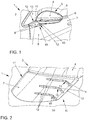
- Figure 1 shows a perspective view of a portion of a motor vehicle 1 which has an exterior mirror device 3 in the area of a front vehicle door 2.
- the outside mirror device 3 has a mirror housing 4, which is in Figure 1 only shows dashed lines 5 mirror, which serves a driver of motor vehicle 1 as an outside mirror.
- the mirror housing 4 is designed to be flow-optimized and also has a controllable light strip 6, which is used, for example, as a turn signal.
- the mirror housing 4 is fastened to an outer skin 8 of the motor vehicle 1 by a mirror base 7.
- the outer skin 8 is formed by a trim part 9 of the vehicle door 2.
- the mirror base 7 rests on the outer skin 8, but is preferably firmly connected to a body element arranged below the outer skin 8 or trim part 9. In the present case, the mirror base 7 lies directly below a window 10 on the trim part 9.
- the mirror base 7 is designed such that it extends obliquely from its end facing the vehicle door 2 to the mirror housing 4, its end facing the vehicle door 2 protruding in the direction of travel, which provides an aerodynamically advantageous design of the exterior mirror device 3, which in particular provides a high robustness guaranteed.
- the mirror base 7 On the underside 11 facing the carriageway and on the upper side 11 'facing away from the underside 11, the mirror base 7 each has a plurality of flow guide elements 12 which serve to advantageously guide the air flow caused by the airstream to avoid wind noise and turbulence.
- FIG. 2 shows a perspective detailed view of the underside 11 of the mirror base 7.
- the mirror base 7 has three flow guide elements 12 which extend along the underside 11 in the direction of a detaching edge 13 of the mirror base 7.
- the flow guide elements 11 are each designed as a web element 14.
- the flow control elements 12 extend parallel to each other and each have a curved section 15. It is thereby achieved that the flow guide elements 12 at their beginning or beginning in the flow direction extend parallel to the normal flow direction of the wind when the motor vehicle 1 is moving forward, and at their end facing the separation edge 13 perpendicular to the separation edge 13.
- the flow control elements 12 on the top 11 are trained accordingly.
- the air flow on the underside 11 of the mirror base 7 is diverted perpendicularly to the detaching edge 13, as a result of which the drag coefficient of the exterior mirror device 3 and sound emissions, in particular of the mirror base 7, are reduced to a level which approximately corresponds to the level of a mirror base which does not have an oblique detaching edge 13 or no oblique configuration of the mirror base 7, as is provided here.
- the flow guide elements 12 as web elements 14, it is also conceivable to design the flow guide elements 12 as groove-shaped depressions on the underside 11 of the mirror base 7.
- a camera sensor is arranged in the mirror housing 4 instead of a mirror element 5, so that the exterior mirror device forms a digital exterior mirror device which, in particular in the interior of the motor vehicle, has a display device for displaying the image of the surroundings of the motor vehicle captured by the camera sensor.
Landscapes
- Engineering & Computer Science (AREA)
- Mechanical Engineering (AREA)
- Multimedia (AREA)
- Chemical & Material Sciences (AREA)
- Combustion & Propulsion (AREA)
- Transportation (AREA)
- Rear-View Mirror Devices That Are Mounted On The Exterior Of The Vehicle (AREA)
Abstract
Description
- Die Erfindung betrifft eine Außenspiegelvorrichtung für ein Kraftfahrzeug, mit einem Spiegelgehäuse, in welchem zumindest ein Spiegelelement und/oder mindestens ein Kamerasensor angeordnet ist, mit einem Spiegelfuß, der einendig das Spiegelgehäuse trägt und anderendig an dem Kraftfahrzeug befestigbar oder befestigt ist und mit zumindest einem Strömungsleitelement zum Beeinflussen, insbesondere Verbessern, einer Luftströmung an der Außenspiegelvorrichtung.
- Weiterhin betrifft die Erfindung ein Kraftfahrzeug mit einer derartigen Außenspiegelvorrichtung.
- Eine Außenspiegelvorrichtung ist beispielsweise aus der Offenlegungsschrift
DE 10 2010 017 373 A1 bekannt. Diese weist ein Spiegelgehäuse auf, in welchem ein Spiegel verstellbar angeordnet ist, sowie einen Spiegelfuß, durch welchen das Spiegelgehäuse an der Außenkante des Kraftfahrzeugs angeordnet ist. Darüber hinaus ist dem Spiegelgehäuse ein Luftleitelement zugeordnet, das optional auch verstellbar ist, um einen Luftstrom in Richtung des Spiegels zu lenken, um diesen von gegebenenfalls darauf befindlichen Wassertopfen zu befreien. - Aus der Offenlegungsschrift
US 5,903,389 B1 ist eine weitere Außenspiegelvorrichtung bekannt, bei welcher am Spiegelgehäuse mehrere Luftleitelemente ausgebildet sind, um eine verbesserte Ablösung einer Luftströmung während des Fahrbetriebs sowie ein verbessertes Geräuschverhalten zu erzielen. - Der Erfindung liegt die Aufgabe zugrunde, eine verbesserte Außenspiegelvorrichtung zu schaffen, bei welcher das Strömungsverhalten der Luft im Fahrbetrieb weiter verbessert insbesondere Strömungsgeräusche und Windwiderstand reduziert werden.
- Die der Erfindung zugrundeliegende Aufgabe wird durch eine Außenspiegelvorrichtung mit den Merkmalen des Anspruchs 1 gelöst. Diese hat den Vorteil, dass eine wirbelbehaftete Ablösung der Strömung am Spiegelfuß reduziert oder vermieden wird. Erfindungsgemäß wird hierdurch erreicht, dass das Strömungsleitelement an dem Spiegelfuß derart ausgebildet ist, dass es senkrecht zur Ablösekante der Strömung an dem Spiegelfuß an der Ablösekante endet. Das Strömungsleitelement erstreckt sich somit entlang des Spiegelfuß, wobei es sich zumindest im Endabschnitt im Bereich der Ablösekante senkrecht zur Ablösekante erstreckt, sodass die Strömung senkrecht zur Ablösekante geführt ist. Dadurch wird das Strömungsverhalten am Spiegelfuß verbessert und die Geräuschemission reduziert. Durch das Anordnen der Strömungsleitelemente am Spiegelfuß wird die Luftströmung insbesondere im Bereich nahe zu der Fahrzeugkarosserie beziehungsweise der Fahrzeugaußenhaut beeinflusst, sodass insbesondere an der Außenhaut entstehende Geräusche durch den Fahrtwind vermieden oder zumindest reduziert werden.
- Gemäß einer bevorzugten Weiterbildung der Erfindung sind mehrere parallel zueinander verlaufend ausgebildete Strömungsleitelemente an dem Spiegelfuß angeordnet. Je nach Größe des Spiegelfuß, also je nach Längserstreckung von dem Kraftfahrzeug bis zum Spiegelgehäuse ist die Anzahl der Strömungsleitelemente reduziert oder erhöht, wobei mit zunehmender Länge die Anzahl der Strömungsleitelemente ebenfalls erhöht wird. Dadurch ist über die Längserstreckung des Spiegelfuß gewährleistet, dass eine vorteilhafte Luftströmungsführung erfolgt.
- Gemäß einer bevorzugten Weiterbildung der Erfindung ist das jeweilige Strömungsleitelement, also das zumindest eine Strömungsleitelement oder die mehreren Strömungsleitelemente, jeweils einstückig mit dem Spiegelfuß, insbesondere mit einem Fußgehäuse des Spiegelfuß ausgebildet. Dadurch ist eine vorteilhafte Integration des jeweiligen Strömungsleitelements in den Spiegelfuß gewährleistet, die insbesondere eine nachträgliche Montage vermeidet. Alternativ ist das jeweilige Strömungsleitelement als separates Element ausgebildet und an dem Fußgehäuse des Spiegelfuß befestigt.
- Weiterhin ist vorteilhaft vorgesehen, dass das jeweilige Strömungsleitelement als von dem Spiegelfuß vorstehendes Stegelement ausgebildet ist. Dadurch steht das jeweilige Strömungsleitelement von dem Spiegelfuß vor und erlaubt kostengünstig eine vorteilhafte Luftströmungsführung.
- Alternativ ist das jeweilige Strömungsleitelement als nutförmige Vertiefung in dem Spiegelfuß ausgebildet, sodass die Luftführung durch die nutförmige Vertiefung erfolgt. Zweckmäßigerweise endet die nutförmige Vertiefung randoffen an der Ablösekante des Spiegelfuß. Die Ablösekante kann beispielsweise durch Berechnungen und/oder Versuche zuvor ermittelt oder konstruktiv ausgebildet werden.
- Gemäß einer bevorzugten Weiterbildung der Erfindung weist das jeweilige Strömungsleitelement zumindest einen gekrümmten Abschnitt in seiner Längserstreckung auf, insbesondere um als Wirbelstromgenerator zu wirken. Durch die Krümmung wird erreicht, dass die Luftströmungsrichtung verändert, wodurch insbesondere Wirbelströme an der Ablösekante entstehen, die insbesondere im Bereich der Ablösekante zu einem verbesserten Ablöseverhalten führen. Dies ist insbesondere dann der Fall, wenn die Ablösekante sich nicht senkrecht zur Fahrtrichtung erstreckt. Bevorzugt erstreckt sich die Ablösekante nicht senkrecht zur Luftströmungsrichtung in Fahrtrichtung, sondern schräg zur normalen Luftströmungsrichtung, sodass der Spiegelfuß mechanisch für das Tragen des Spiegelgehäuses optimal auslegbar und konstruierbar ist. Insbesondere ist der Spiegelfuß insgesamt schräg gestellt ausgebildet, um die Tragfähigkeit des Spiegelfuß zu optimieren.
- Weiterhin ist bevorzugt vorgesehen, dass das jeweilige Strömungsleitelement parallel zu einem Luftströmungsrichtung an dem Spiegelfuß beginnt. Insbesondere durch die Krümmung wird dann die Luftströmungsrichtung aus der Normalströmrichtung in die davon abweichende Strömungsrichtung senkrecht zur Ablösekante gelenkt, um das vorteilhafte Strömungsverhalten zu erreichen. Dadurch, dass das jeweilige Strömungsleitelement in Normalluftströmungsrichtung ausgerichtet beginnt, wird ein vorteilhaftes Aufnehmen des Luftraums beziehungsweise des Fahrtwinds mit einer geringen Geräuschemission und geringem Widerstand gewährleistet.
- Gemäß einer bevorzugten Weiterbildung der Erfindung ist an einer Oberseite und/oder an einer Unterseite des Spiegelfuß jeweils zumindest ein Strömungsleitelement angeordnet. Das jeweilige Strömungsleitelement an der Unterseite ist für den Benutzer in der Regel nicht sichtbar, was den optischen Eindruck verbessert. Darüber hinaus wird vermieden, dass die Funktion der Strömungsleitelemente durch beispielsweise Eis- oder Schneebildung auf der Oberseite des Spiegelfuß vermindert wird. Vorzugsweise sind an der Oberseite und der Unterseite jeweils mehrere Strömungsleitelemente angeordnet.
- Weiterhin ist bevorzugt vorgesehen, dass der Spiegelfuß dazu ausgebildet ist, wie vorstehend bereits erwähnt, schräg von dem Kraftfahrzeug zu dem Spiegelgehäuse an dem Kraftfahrzeug zu verlaufen, um mechanische Vorteile zu erreichen, die eine robuste Halterung des Spiegelgehäuses auch bei hohen Luftströmungsgeschwindigkeiten gewährleistet. Dies hat insbesondere zur Folge, dass die Ablösekante des Spiegelfuß sich nicht senkrecht, sondern schräg zur Luftströmungsrichtung bei Geradeausfahrt beziehungsweise zur Fahrtrichtung oder Längserstreckung des Kraftfahrzeugs erstreckt.
- Das erfindungsgemäße Kraftfahrzeugs zeichnet sich durch die erfindungsgemäße Ausbildung der Spiegelvorrichtung aus. Es ergeben sich hierdurch die bereits genannten Vorteile.
- Weitere Vorteile und bevorzugte Merkmale und Merkmalskombinationen ergeben sich insbesondere aus dem zuvor Beschriebenen sowie aus den Ansprüchen. Im Folgenden soll die Erfindung anhand der Zeichnung näher erläutert werden. Dazu zeigen
- Figur 1
- ein Kraftfahrzeug mit einer vorteilhaften Spiegelvorrichtung in einer vereinfachten Detaildarstellung und
- Figur 2
- eine perspektivische Detaildarstellung der Spiegelvorrichtung.
-
Figur 1 zeigt in einer perspektivischen Darstellung einen Abschnitt eines Kraftfahrzeugs 1, das im Bereich einer vorderen Fahrzeugtür 2 eine Außenspiegelvorrichtung 3 aufweist. Die Außenspiegelvorrichtung 3 weist ein Spiegelgehäuse 4 auf, das einen inFigur 1 nur gestrichelt dargestellten Spiegel 5 trägt, der einem Fahrer des Kraftfahrzeus 1 als Außenspiegel dient. Das Spiegelgehäuse 4 ist dabei strömungsoptimiert ausgebildet und weist außerdem einen ansteuerbaren Leuchtstreifen 6, der beispielsweise als Blinker verwendet wird, auf. - Das Spiegelgehäuse 4 ist durch einen Spiegelfuß 7 an einer Außenhaut 8 des Kraftfahrzeugs 1 befestigt. In diesem Fall wird die Außenhaut 8 von einem Verkleidungsteil 9 der Fahrzeugtür 2 gebildet. Der Spiegelfuß 7 setzt auf der Außenhaut 8 auf, ist jedoch bevorzugt mit einem unterhalb der Außenhaut 8 beziehungsweise Verkleidungsteils 9 angeordneten Karosserieelements fest verbunden. Vorliegend liegt dabei der Spiegelfuß 7 direkt unterhalb eines Fensters 10 auf dem Verkleidungsteil 9 auf.
- Der Spiegelfuß 7 ist dabei derart ausgebildet, dass er sich schräg von seinem der Fahrzeugtür 2 zugewandten Ende zu dem Spiegelgehäuse 4 erstreckt, wobei sein der Fahrzeugtür 2 zugewandtes Ende in Fahrtrichtung vorsteht, wodurch eine aerodynamisch vorteilhafte Ausbildung der Außenspiegelvorrichtung 3 geboten wird, die insbesondere eine hohe Robustheit gewährleistet.
- An der der Fahrbahn zugewandten Unterseite 11 sowie an der von der Unterseite 11 abgewandten Oberseite 11' weist der Spiegelfuß 7 jeweils mehrere Strömungsleitelemente 12 auf, die dazu dienen, die durch den Fahrtwind bedingte Luftströmung vorteilhaft zur Vermeidung von Windgeräuschen und Verwirbelungen zu führen.
-
Figur 2 zeigt eine perspektivische Detailansicht der Unterseite 11 des Spiegelfuß 7. Vorliegend weist der Spiegelfuß 7 drei Strömungsleitelemente 12 auf, die sich entlang der Unterseite 11 in Richtung einer Ablösekante 13 des Spiegelfuß 7 erstrecken. Dabei sind die Strömungsleitelemente 11 jeweils als Stegelement 14 ausgebildet. Die Strömungsleitelemente 12 erstrecken sich parallel zueinander und weisen jeweils einen gekrümmten Abschnitt 15 auf. Dadurch wird erreicht, dass die Strömungsleitelemente 12 an ihrem in Strömungsrichtung vorneliegenden Anfang oder Beginn sich parallel zur Normalströmungsrichtung des Fahrtwindes bei Vorwärtsbewegung des Kraftfahrzeugs 1 erstrecken, und an ihrem der Ablösekante 13 zugewandten Ende senkrecht zu der Ablösekante 13. Die Strömungsleitelemente 12 auf der Oberseite 11' sind entsprechend ausgebildet. - Dadurch wird der Luftstrom an der Unterseite 11 des Spiegelfuß 7 senkrecht zur Ablösekante 13 umgeleitet, wodurch der cW-Wert der Außenspiegelvorrichtung 3 sowie Schallemissionen insbesondere des Spiegelfuß 7 auf ein Niveau reduziert werden, das in etwa den Niveau eines Spiegelfuß entspricht, der keine schräge Ablösekante 13 beziehungsweise keine schräge Ausbildung des Spiegelfuß 7, wie sie vorliegend vorgesehen ist, aufweist.
- Alternativ zu der dargestellten Ausführung der Strömungsleitelemente 12 als Stegelemente 14 ist es auch denkbar, die Strömungsleitelemente 12 als nutförmige Vertiefungen an der Unterseite 11 des Spiegelfuß 7 auszubilden.
- Alternativ zu dem vorstehend dargestellten Ausführungsbeispiel ist in dem Spiegelgehäuse 4 anstelle eines Spiegelelements 5 ein Kamerasensor angeordnet, sodass die Außenspiegelvorrichtung eine digitale Außenspiegelvorrichtung ausbildet, welche insbesondere im Innenraum des Kraftfahrzeugs eine Anzeigeeinrichtung zum Darstellen des von dem Kamerasensor erfassten Bilds der Umgebung des Kraftfahrzeugs aufweist.
-
- 1
- Kraftfahrzeug
- 2
- Fahrzeugtür
- 3
- Außenspiegelvorrichtung
- 4
- Spiegelgehäuse
- 5
- Spiegelelement
- 6
- Leuchtstreifen
- 7
- Spiegelfuß
- 8
- Außenhaut
- 9
- Verkleidungsteil
- 10
- Fenster
- 11
- Unterseite
- 11'
- Oberseite
- 12
- Strömungsleitelement
- 13
- Ablösekante
- 14
- Stegelement
- 15
- Abschnitt
Claims (10)
- Außenspiegelvorrichtung (3) für ein Kraftfahrzeug (1), mit einem Spiegelgehäuse (4), in welchem zumindest ein Spiegelelement (5) und/oder ein Kamerasensor angeordnet ist, mit einem Spiegelfuß (7), der einendig das Spiegelgehäuse (4) trägt und anderendig an dem Kraftfahrzeug (1) befestigbar oder befestigt ist, und mit zumindest einem Strömungsleitelement (12) zum Beeinflussen einer Luftströmung an der Außenspiegelvorrichtung (3), dadurch gekennzeichnet, dass das Strömungsleitelement (12) an dem Spiegelfuß (7) derart ausgebildet ist, dass es senkrecht zur Ablösekante (13) der Luftströmung an dem Spiegelfuß (7) an der Ablösekante (13) endet.
- Außenspiegelvorrichtung nach Anspruch 1, dadurch gekennzeichnet, dass mehrere parallel zueinander verlaufend ausgebildete Strömungsleitelemente (12) an dem Spiegelfuß (7) angeordnet sind.
- Außenspiegelvorrichtung nach einem der vorhergehenden Ansprüche, dadurch gekennzeichnet, dass das jeweilige Strömungsleitelement (12) einstückig mit dem Spiegelfuß (7) ausgebildet ist.
- Außenspiegelvorrichtung nach einem der vorhergehenden Ansprüche, dadurch gekennzeichnet, dass das jeweilige Strömungsleitelement (12) als von dem Spiegelfuß (7) vorstehendes Stegelement (14) ausgebildet ist.
- Außenspiegelvorrichtung nach einem der vorhergehenden Ansprüche, dadurch gekennzeichnet, dass das jeweilige Strömungsleitelement (12) als nutförmige Vertiefung in dem Spiegelfuß (7) ausgebildet ist.
- Außenspiegelvorrichtung nach einem der vorhergehenden Ansprüche, dadurch gekennzeichnet, dass das jeweilige Strömungsleitelement (12) zumindest einen gekrümmten Abschnitt (15) in seiner Längserstreckung aufweist.
- Außenspiegelvorrichtung nach einem der vorhergehenden Ansprüche, dadurch gekennzeichnet, dass das jeweilige Strömungsleitelement (12) parallel zu einer Normalluftanströmrichtung an dem Spiegelfuß (7) beginnt.
- Außenspiegelvorrichtung nach einem der vorhergehenden Ansprüche, dadurch gekennzeichnet, dass an einer Unterseite (11) und/oder an einer Oberseite (11') des Spiegelfuß (7) jeweils zumindest ein Strömungsleitelement (12) angeordnet ist.
- Außenspiegelvorrichtung nach einem der vorhergehenden Ansprüche, dadurch gekennzeichnet, dass der Spiegelfuß (7) dazu ausgebildet ist, schräg von dem Kraftfahrzeug (1) zu dem Spiegelgehäuse (4) an dem Kraftfahrzeug (1) zu verlaufen.
- Kraftahrzeug (1) mit wenigstens einer an seiner Außenhaut (8) angeordneten Außenspiegelvorrichtung (3), gekennzeichnet durch die Ausbildung der Außenspiegelvorrichtung (3) nach einem der Ansprüche 1 bis 9.
Applications Claiming Priority (1)
| Application Number | Priority Date | Filing Date | Title |
|---|---|---|---|
| DE102018213221.6A DE102018213221A1 (de) | 2018-08-07 | 2018-08-07 | Außenspiegelvorrichtung für ein Kraftfahrzeug, Kraftfahrzeug |
Publications (2)
| Publication Number | Publication Date |
|---|---|
| EP3608173A1 true EP3608173A1 (de) | 2020-02-12 |
| EP3608173B1 EP3608173B1 (de) | 2021-04-07 |
Family
ID=67551226
Family Applications (1)
| Application Number | Title | Priority Date | Filing Date |
|---|---|---|---|
| EP19190411.9A Active EP3608173B1 (de) | 2018-08-07 | 2019-08-07 | Aussenspiegelvorrichtung für ein kraftfahrzeug, kraftfahrzeug |
Country Status (5)
| Country | Link |
|---|---|
| US (1) | US11351920B2 (de) |
| EP (1) | EP3608173B1 (de) |
| KR (1) | KR102231128B1 (de) |
| CN (1) | CN110816412B (de) |
| DE (1) | DE102018213221A1 (de) |
Families Citing this family (3)
| Publication number | Priority date | Publication date | Assignee | Title |
|---|---|---|---|---|
| US11273766B2 (en) * | 2012-01-24 | 2022-03-15 | Motherson Innovations Company Limited | Light emitting mirror bezel |
| US12539814B2 (en) * | 2022-01-18 | 2026-02-03 | INDIAN INSTITUTE OF TECHNOLOGY MADRAS (IIT Madras) | Method and side-view mirror system of vehicle for monitoring ambient parameters during vehicle mobility |
| GB202413894D0 (en) * | 2024-09-20 | 2024-11-06 | Mclaren Automotive Ltd | Side mirror aerodynamic device |
Citations (6)
| Publication number | Priority date | Publication date | Assignee | Title |
|---|---|---|---|---|
| DE2704226B1 (de) * | 1977-02-02 | 1978-08-03 | Audi Nsu Auto Union Ag | Aussenspiegel fuer Kraftfahrzeuge |
| US5903389A (en) | 1996-08-13 | 1999-05-11 | Daimler-Benz Ag | Outside rear view mirror for a motor vehicle |
| DE102005019778A1 (de) * | 2005-04-28 | 2006-11-02 | Audi Ag | Spiegelgehäuse |
| EP1787862A1 (de) * | 2005-11-18 | 2007-05-23 | Peugeot Citroen Automobiles | Rückspiegel mit einem Gehäuse versehen mit Wellen |
| DE102010017373A1 (de) | 2010-06-15 | 2011-12-15 | Dr. Ing. H.C. F. Porsche Aktiengesellschaft | Kraftfahrzeug |
| US20150266425A1 (en) * | 2014-03-19 | 2015-09-24 | Mitsubishi Jidosha Kogyo Kabushiki Kaisha | Door mirror of vehicle |
Family Cites Families (15)
| Publication number | Priority date | Publication date | Assignee | Title |
|---|---|---|---|---|
| US3859899A (en) * | 1974-02-14 | 1975-01-14 | John Edward Mills | Interior ventilation system with side view mirror de-icing |
| US4196930A (en) * | 1978-12-01 | 1980-04-08 | Busche Oscar H | Wind deflector for preventing the accumulation of foreign matter on a motor vehicle side view mirror |
| DE3132400C2 (de) * | 1981-08-17 | 1983-06-16 | Ford-Werke AG, 5000 Köln | Außenrückspiegel für Kraftfahrzeuge, mit einem an der vorderen Seitenscheibe des Kraftfahrzeuges anliegend angeordneten, strömungsgünstigen Spiegelgehäuse |
| US4538851A (en) * | 1984-01-18 | 1985-09-03 | General Motors Corporation | Aerodynamic rear view mirror |
| US4898458A (en) * | 1989-01-01 | 1990-02-06 | Mcdonald William H | Laminar air flow exterior adjustable rearview mirror |
| US4981072A (en) * | 1990-03-16 | 1991-01-01 | Sheller-Globe Corporation | Exterior rear view mirror assembly with ventilator for exterior side window |
| DE4039484C2 (de) * | 1990-12-11 | 1993-11-18 | Bayerische Motoren Werke Ag | Außenrückblickspiegel für Kraftfahrzeuge |
| US6386712B1 (en) * | 2000-11-08 | 2002-05-14 | Daimlerchrysler Corporation | Exterior rear view mirror having water removal hole with turbulent flow generator |
| JP3717823B2 (ja) * | 2001-08-02 | 2005-11-16 | 株式会社村上開明堂 | 自動車用ドアミラー |
| US6712413B1 (en) * | 2002-09-20 | 2004-03-30 | Daimlerchrysler Corporation | Anti-buffeting vehicle mirror assembly |
| KR100808697B1 (ko) | 2006-10-04 | 2008-02-29 | 지엠대우오토앤테크놀로지주식회사 | Osrvm 장착용 베이스 플레이트 |
| EP2392495B1 (de) * | 2010-06-04 | 2012-09-05 | SMR Patents S.à.r.l. | Außenrückblickspiegel mit Luftführung |
| CN102529820A (zh) * | 2012-01-05 | 2012-07-04 | 重庆长安汽车股份有限公司 | 一种降低汽车后视镜涡流噪声的扰流构件 |
| DE102013011187A1 (de) * | 2013-07-04 | 2014-03-27 | Daimler Ag | Außenspiegel, insbesondere für ein Kraftfahrzeug |
| DE102016118447A1 (de) * | 2016-09-29 | 2018-03-29 | Dr. Ing. H.C. F. Porsche Aktiengesellschaft | Kraftfahrzeug-Außenspiegel |
-
2018
- 2018-08-07 DE DE102018213221.6A patent/DE102018213221A1/de not_active Withdrawn
-
2019
- 2019-08-02 CN CN201910710636.8A patent/CN110816412B/zh active Active
- 2019-08-06 KR KR1020190095327A patent/KR102231128B1/ko active Active
- 2019-08-07 EP EP19190411.9A patent/EP3608173B1/de active Active
- 2019-08-07 US US16/534,299 patent/US11351920B2/en active Active
Patent Citations (6)
| Publication number | Priority date | Publication date | Assignee | Title |
|---|---|---|---|---|
| DE2704226B1 (de) * | 1977-02-02 | 1978-08-03 | Audi Nsu Auto Union Ag | Aussenspiegel fuer Kraftfahrzeuge |
| US5903389A (en) | 1996-08-13 | 1999-05-11 | Daimler-Benz Ag | Outside rear view mirror for a motor vehicle |
| DE102005019778A1 (de) * | 2005-04-28 | 2006-11-02 | Audi Ag | Spiegelgehäuse |
| EP1787862A1 (de) * | 2005-11-18 | 2007-05-23 | Peugeot Citroen Automobiles | Rückspiegel mit einem Gehäuse versehen mit Wellen |
| DE102010017373A1 (de) | 2010-06-15 | 2011-12-15 | Dr. Ing. H.C. F. Porsche Aktiengesellschaft | Kraftfahrzeug |
| US20150266425A1 (en) * | 2014-03-19 | 2015-09-24 | Mitsubishi Jidosha Kogyo Kabushiki Kaisha | Door mirror of vehicle |
Also Published As
| Publication number | Publication date |
|---|---|
| EP3608173B1 (de) | 2021-04-07 |
| US20200047672A1 (en) | 2020-02-13 |
| KR102231128B1 (ko) | 2021-03-23 |
| CN110816412B (zh) | 2023-04-07 |
| DE102018213221A1 (de) | 2020-02-13 |
| KR20200016801A (ko) | 2020-02-17 |
| CN110816412A (zh) | 2020-02-21 |
| US11351920B2 (en) | 2022-06-07 |
Similar Documents
| Publication | Publication Date | Title |
|---|---|---|
| DE102004004360B4 (de) | Kraftfahrzeug mit einer Luftleiteinrichtung | |
| DE102010004560A1 (de) | Personenkraftfahrzeug mit heckseitiger Luftleitvorrichtung | |
| DE102016118127B4 (de) | Fahrzeug mit einem Gleichrichter | |
| DE102014104157A1 (de) | Heckseitige Luftleitvorrichtung | |
| EP3608173B1 (de) | Aussenspiegelvorrichtung für ein kraftfahrzeug, kraftfahrzeug | |
| DE102008006103A1 (de) | Kraftfahrzeug | |
| DE102016114291B4 (de) | Struktur eines Kamerabefestigungsteils | |
| DE102016105994A1 (de) | Heckseitige Luftleiteinrichtung für ein Kraftfahrzeug | |
| DE102016111429B4 (de) | Luftleitvorrichtung für ein Fahrzeug, Fahrzeug mit einer Luftleitvorrichtung und Verfahren zum Betrieb einer Luftleitvorrichtung | |
| DE102007031074A1 (de) | Kraftfahrzeug mit einer A-Säule | |
| DE102015011522A1 (de) | Fahrerassistenzvorrichtung | |
| DE19644171B4 (de) | Verkleidung für eine axial und in der Höhe verstellbare Lenksäule | |
| EP1733922A1 (de) | Kraftfahrzeug, insbesondere Personenkraftwagen | |
| DE102018114519B4 (de) | Strömungsleitanordnung | |
| DE102004043544B4 (de) | Spoiler | |
| DE102009038935A1 (de) | Erkennungseinrichtung für ein Schiebe- und/oder Hebedach eines Kraftwagens | |
| DE102005038808A1 (de) | Anordnung eines Emblems am Ende eines Kraftwagens | |
| DE102012016138A1 (de) | Außenspiegeleinrichtung für einen Kraftwagen sowie Anordnung einer Außenspiegeleinrichtung an einem Kraftwagen | |
| DE102020003192A1 (de) | Unterbodenverkleidungselement für ein Fahrzeug sowie Anordnung einer Unterbodenverkleidung an einem Aufbau eines Fahrzeugs | |
| DE102015013046A1 (de) | Fahrzeug | |
| DE19607886A1 (de) | Lastkraftwagen der Frontlenkerbauart mit am Fahrerhaus angeordneten, als Luftleitdüsen ausgebildeten Eckblenden | |
| DE102014110390A1 (de) | Strömungsleitvorrichtung | |
| DE102019104504A1 (de) | Kraftfahrzeug | |
| DE102009051031B3 (de) | Luftausströmer für Fahrzeuge | |
| DE102022116495B4 (de) | Kraftfahrzeug und Verfahren zur Steuerung eines Betriebs eines verstellbaren Luftleitelements eines Kraftfahrzeugs |
Legal Events
| Date | Code | Title | Description |
|---|---|---|---|
| PUAI | Public reference made under article 153(3) epc to a published international application that has entered the european phase |
Free format text: ORIGINAL CODE: 0009012 |
|
| STAA | Information on the status of an ep patent application or granted ep patent |
Free format text: STATUS: THE APPLICATION HAS BEEN PUBLISHED |
|
| AK | Designated contracting states |
Kind code of ref document: A1 Designated state(s): AL AT BE BG CH CY CZ DE DK EE ES FI FR GB GR HR HU IE IS IT LI LT LU LV MC MK MT NL NO PL PT RO RS SE SI SK SM TR |
|
| AX | Request for extension of the european patent |
Extension state: BA ME |
|
| STAA | Information on the status of an ep patent application or granted ep patent |
Free format text: STATUS: REQUEST FOR EXAMINATION WAS MADE |
|
| 17P | Request for examination filed |
Effective date: 20200812 |
|
| RBV | Designated contracting states (corrected) |
Designated state(s): AL AT BE BG CH CY CZ DE DK EE ES FI FR GB GR HR HU IE IS IT LI LT LU LV MC MK MT NL NO PL PT RO RS SE SI SK SM TR |
|
| GRAP | Despatch of communication of intention to grant a patent |
Free format text: ORIGINAL CODE: EPIDOSNIGR1 |
|
| STAA | Information on the status of an ep patent application or granted ep patent |
Free format text: STATUS: GRANT OF PATENT IS INTENDED |
|
| INTG | Intention to grant announced |
Effective date: 20201102 |
|
| GRAS | Grant fee paid |
Free format text: ORIGINAL CODE: EPIDOSNIGR3 |
|
| GRAA | (expected) grant |
Free format text: ORIGINAL CODE: 0009210 |
|
| STAA | Information on the status of an ep patent application or granted ep patent |
Free format text: STATUS: THE PATENT HAS BEEN GRANTED |
|
| AK | Designated contracting states |
Kind code of ref document: B1 Designated state(s): AL AT BE BG CH CY CZ DE DK EE ES FI FR GB GR HR HU IE IS IT LI LT LU LV MC MK MT NL NO PL PT RO RS SE SI SK SM TR |
|
| REG | Reference to a national code |
Ref country code: GB Ref legal event code: FG4D Free format text: NOT ENGLISH |
|
| REG | Reference to a national code |
Ref country code: AT Ref legal event code: REF Ref document number: 1379286 Country of ref document: AT Kind code of ref document: T Effective date: 20210415 Ref country code: CH Ref legal event code: EP |
|
| REG | Reference to a national code |
Ref country code: DE Ref legal event code: R096 Ref document number: 502019001173 Country of ref document: DE |
|
| REG | Reference to a national code |
Ref country code: IE Ref legal event code: FG4D Free format text: LANGUAGE OF EP DOCUMENT: GERMAN |
|
| REG | Reference to a national code |
Ref country code: LT Ref legal event code: MG9D |
|
| REG | Reference to a national code |
Ref country code: NL Ref legal event code: MP Effective date: 20210407 |
|
| PG25 | Lapsed in a contracting state [announced via postgrant information from national office to epo] |
Ref country code: NL Free format text: LAPSE BECAUSE OF FAILURE TO SUBMIT A TRANSLATION OF THE DESCRIPTION OR TO PAY THE FEE WITHIN THE PRESCRIBED TIME-LIMIT Effective date: 20210407 Ref country code: FI Free format text: LAPSE BECAUSE OF FAILURE TO SUBMIT A TRANSLATION OF THE DESCRIPTION OR TO PAY THE FEE WITHIN THE PRESCRIBED TIME-LIMIT Effective date: 20210407 Ref country code: LT Free format text: LAPSE BECAUSE OF FAILURE TO SUBMIT A TRANSLATION OF THE DESCRIPTION OR TO PAY THE FEE WITHIN THE PRESCRIBED TIME-LIMIT Effective date: 20210407 Ref country code: HR Free format text: LAPSE BECAUSE OF FAILURE TO SUBMIT A TRANSLATION OF THE DESCRIPTION OR TO PAY THE FEE WITHIN THE PRESCRIBED TIME-LIMIT Effective date: 20210407 Ref country code: BG Free format text: LAPSE BECAUSE OF FAILURE TO SUBMIT A TRANSLATION OF THE DESCRIPTION OR TO PAY THE FEE WITHIN THE PRESCRIBED TIME-LIMIT Effective date: 20210707 |
|
| PG25 | Lapsed in a contracting state [announced via postgrant information from national office to epo] |
Ref country code: SE Free format text: LAPSE BECAUSE OF FAILURE TO SUBMIT A TRANSLATION OF THE DESCRIPTION OR TO PAY THE FEE WITHIN THE PRESCRIBED TIME-LIMIT Effective date: 20210407 Ref country code: PT Free format text: LAPSE BECAUSE OF FAILURE TO SUBMIT A TRANSLATION OF THE DESCRIPTION OR TO PAY THE FEE WITHIN THE PRESCRIBED TIME-LIMIT Effective date: 20210809 Ref country code: RS Free format text: LAPSE BECAUSE OF FAILURE TO SUBMIT A TRANSLATION OF THE DESCRIPTION OR TO PAY THE FEE WITHIN THE PRESCRIBED TIME-LIMIT Effective date: 20210407 Ref country code: NO Free format text: LAPSE BECAUSE OF FAILURE TO SUBMIT A TRANSLATION OF THE DESCRIPTION OR TO PAY THE FEE WITHIN THE PRESCRIBED TIME-LIMIT Effective date: 20210707 Ref country code: PL Free format text: LAPSE BECAUSE OF FAILURE TO SUBMIT A TRANSLATION OF THE DESCRIPTION OR TO PAY THE FEE WITHIN THE PRESCRIBED TIME-LIMIT Effective date: 20210407 Ref country code: LV Free format text: LAPSE BECAUSE OF FAILURE TO SUBMIT A TRANSLATION OF THE DESCRIPTION OR TO PAY THE FEE WITHIN THE PRESCRIBED TIME-LIMIT Effective date: 20210407 Ref country code: GR Free format text: LAPSE BECAUSE OF FAILURE TO SUBMIT A TRANSLATION OF THE DESCRIPTION OR TO PAY THE FEE WITHIN THE PRESCRIBED TIME-LIMIT Effective date: 20210708 Ref country code: IS Free format text: LAPSE BECAUSE OF FAILURE TO SUBMIT A TRANSLATION OF THE DESCRIPTION OR TO PAY THE FEE WITHIN THE PRESCRIBED TIME-LIMIT Effective date: 20210807 |
|
| REG | Reference to a national code |
Ref country code: DE Ref legal event code: R097 Ref document number: 502019001173 Country of ref document: DE |
|
| PG25 | Lapsed in a contracting state [announced via postgrant information from national office to epo] |
Ref country code: EE Free format text: LAPSE BECAUSE OF FAILURE TO SUBMIT A TRANSLATION OF THE DESCRIPTION OR TO PAY THE FEE WITHIN THE PRESCRIBED TIME-LIMIT Effective date: 20210407 Ref country code: ES Free format text: LAPSE BECAUSE OF FAILURE TO SUBMIT A TRANSLATION OF THE DESCRIPTION OR TO PAY THE FEE WITHIN THE PRESCRIBED TIME-LIMIT Effective date: 20210407 Ref country code: SK Free format text: LAPSE BECAUSE OF FAILURE TO SUBMIT A TRANSLATION OF THE DESCRIPTION OR TO PAY THE FEE WITHIN THE PRESCRIBED TIME-LIMIT Effective date: 20210407 Ref country code: DK Free format text: LAPSE BECAUSE OF FAILURE TO SUBMIT A TRANSLATION OF THE DESCRIPTION OR TO PAY THE FEE WITHIN THE PRESCRIBED TIME-LIMIT Effective date: 20210407 Ref country code: SM Free format text: LAPSE BECAUSE OF FAILURE TO SUBMIT A TRANSLATION OF THE DESCRIPTION OR TO PAY THE FEE WITHIN THE PRESCRIBED TIME-LIMIT Effective date: 20210407 Ref country code: RO Free format text: LAPSE BECAUSE OF FAILURE TO SUBMIT A TRANSLATION OF THE DESCRIPTION OR TO PAY THE FEE WITHIN THE PRESCRIBED TIME-LIMIT Effective date: 20210407 |
|
| PLBE | No opposition filed within time limit |
Free format text: ORIGINAL CODE: 0009261 |
|
| STAA | Information on the status of an ep patent application or granted ep patent |
Free format text: STATUS: NO OPPOSITION FILED WITHIN TIME LIMIT |
|
| 26N | No opposition filed |
Effective date: 20220110 |
|
| PG25 | Lapsed in a contracting state [announced via postgrant information from national office to epo] |
Ref country code: MC Free format text: LAPSE BECAUSE OF FAILURE TO SUBMIT A TRANSLATION OF THE DESCRIPTION OR TO PAY THE FEE WITHIN THE PRESCRIBED TIME-LIMIT Effective date: 20210407 |
|
| REG | Reference to a national code |
Ref country code: BE Ref legal event code: MM Effective date: 20210831 |
|
| PG25 | Lapsed in a contracting state [announced via postgrant information from national office to epo] |
Ref country code: IS Free format text: LAPSE BECAUSE OF FAILURE TO SUBMIT A TRANSLATION OF THE DESCRIPTION OR TO PAY THE FEE WITHIN THE PRESCRIBED TIME-LIMIT Effective date: 20210807 Ref country code: LU Free format text: LAPSE BECAUSE OF NON-PAYMENT OF DUE FEES Effective date: 20210807 Ref country code: AL Free format text: LAPSE BECAUSE OF FAILURE TO SUBMIT A TRANSLATION OF THE DESCRIPTION OR TO PAY THE FEE WITHIN THE PRESCRIBED TIME-LIMIT Effective date: 20210407 |
|
| PG25 | Lapsed in a contracting state [announced via postgrant information from national office to epo] |
Ref country code: IT Free format text: LAPSE BECAUSE OF FAILURE TO SUBMIT A TRANSLATION OF THE DESCRIPTION OR TO PAY THE FEE WITHIN THE PRESCRIBED TIME-LIMIT Effective date: 20210407 Ref country code: IE Free format text: LAPSE BECAUSE OF NON-PAYMENT OF DUE FEES Effective date: 20210807 Ref country code: BE Free format text: LAPSE BECAUSE OF NON-PAYMENT OF DUE FEES Effective date: 20210831 |
|
| REG | Reference to a national code |
Ref country code: CH Ref legal event code: PL |
|
| PG25 | Lapsed in a contracting state [announced via postgrant information from national office to epo] |
Ref country code: LI Free format text: LAPSE BECAUSE OF NON-PAYMENT OF DUE FEES Effective date: 20220831 Ref country code: CH Free format text: LAPSE BECAUSE OF NON-PAYMENT OF DUE FEES Effective date: 20220831 |
|
| P01 | Opt-out of the competence of the unified patent court (upc) registered |
Effective date: 20230523 |
|
| PG25 | Lapsed in a contracting state [announced via postgrant information from national office to epo] |
Ref country code: CY Free format text: LAPSE BECAUSE OF FAILURE TO SUBMIT A TRANSLATION OF THE DESCRIPTION OR TO PAY THE FEE WITHIN THE PRESCRIBED TIME-LIMIT Effective date: 20210407 |
|
| PG25 | Lapsed in a contracting state [announced via postgrant information from national office to epo] |
Ref country code: HU Free format text: LAPSE BECAUSE OF FAILURE TO SUBMIT A TRANSLATION OF THE DESCRIPTION OR TO PAY THE FEE WITHIN THE PRESCRIBED TIME-LIMIT; INVALID AB INITIO Effective date: 20190807 |
|
| PG25 | Lapsed in a contracting state [announced via postgrant information from national office to epo] |
Ref country code: MK Free format text: LAPSE BECAUSE OF FAILURE TO SUBMIT A TRANSLATION OF THE DESCRIPTION OR TO PAY THE FEE WITHIN THE PRESCRIBED TIME-LIMIT Effective date: 20210407 |
|
| PG25 | Lapsed in a contracting state [announced via postgrant information from national office to epo] |
Ref country code: MT Free format text: LAPSE BECAUSE OF FAILURE TO SUBMIT A TRANSLATION OF THE DESCRIPTION OR TO PAY THE FEE WITHIN THE PRESCRIBED TIME-LIMIT Effective date: 20210407 |
|
| PGFP | Annual fee paid to national office [announced via postgrant information from national office to epo] |
Ref country code: DE Payment date: 20250831 Year of fee payment: 7 |
|
| REG | Reference to a national code |
Ref country code: AT Ref legal event code: MM01 Ref document number: 1379286 Country of ref document: AT Kind code of ref document: T Effective date: 20240807 |
|
| PGFP | Annual fee paid to national office [announced via postgrant information from national office to epo] |
Ref country code: GB Payment date: 20250826 Year of fee payment: 7 |
|
| PG25 | Lapsed in a contracting state [announced via postgrant information from national office to epo] |
Ref country code: AT Free format text: LAPSE BECAUSE OF NON-PAYMENT OF DUE FEES Effective date: 20240807 |
|
| PGFP | Annual fee paid to national office [announced via postgrant information from national office to epo] |
Ref country code: FR Payment date: 20250825 Year of fee payment: 7 |
|
| PGFP | Annual fee paid to national office [announced via postgrant information from national office to epo] |
Ref country code: CZ Payment date: 20250731 Year of fee payment: 7 |
|
| PG25 | Lapsed in a contracting state [announced via postgrant information from national office to epo] |
Ref country code: TR Free format text: LAPSE BECAUSE OF FAILURE TO SUBMIT A TRANSLATION OF THE DESCRIPTION OR TO PAY THE FEE WITHIN THE PRESCRIBED TIME-LIMIT Effective date: 20210407 |
|
| PGFP | Annual fee paid to national office [announced via postgrant information from national office to epo] |
Ref country code: AT Payment date: 20260410 Year of fee payment: 5 |