EP3608151B1 - Pistenraupe mit einem kettenlaufwerk - Google Patents
Pistenraupe mit einem kettenlaufwerk Download PDFInfo
- Publication number
- EP3608151B1 EP3608151B1 EP19184295.4A EP19184295A EP3608151B1 EP 3608151 B1 EP3608151 B1 EP 3608151B1 EP 19184295 A EP19184295 A EP 19184295A EP 3608151 B1 EP3608151 B1 EP 3608151B1
- Authority
- EP
- European Patent Office
- Prior art keywords
- hydrostatic
- snow groomer
- pump
- tiller
- electric
- Prior art date
- Legal status (The legal status is an assumption and is not a legal conclusion. Google has not performed a legal analysis and makes no representation as to the accuracy of the status listed.)
- Active
Links
Images

Classifications
-
- B—PERFORMING OPERATIONS; TRANSPORTING
- B62—LAND VEHICLES FOR TRAVELLING OTHERWISE THAN ON RAILS
- B62D—MOTOR VEHICLES; TRAILERS
- B62D55/00—Endless track vehicles
-
- B—PERFORMING OPERATIONS; TRANSPORTING
- B60—VEHICLES IN GENERAL
- B60K—ARRANGEMENT OR MOUNTING OF PROPULSION UNITS OR OF TRANSMISSIONS IN VEHICLES; ARRANGEMENT OR MOUNTING OF PLURAL DIVERSE PRIME-MOVERS IN VEHICLES; AUXILIARY DRIVES FOR VEHICLES; INSTRUMENTATION OR DASHBOARDS FOR VEHICLES; ARRANGEMENTS IN CONNECTION WITH COOLING, AIR INTAKE, GAS EXHAUST OR FUEL SUPPLY OF PROPULSION UNITS IN VEHICLES
- B60K1/00—Arrangement or mounting of electrical propulsion units
- B60K1/02—Arrangement or mounting of electrical propulsion units comprising more than one electric motor
-
- B—PERFORMING OPERATIONS; TRANSPORTING
- B60—VEHICLES IN GENERAL
- B60K—ARRANGEMENT OR MOUNTING OF PROPULSION UNITS OR OF TRANSMISSIONS IN VEHICLES; ARRANGEMENT OR MOUNTING OF PLURAL DIVERSE PRIME-MOVERS IN VEHICLES; AUXILIARY DRIVES FOR VEHICLES; INSTRUMENTATION OR DASHBOARDS FOR VEHICLES; ARRANGEMENTS IN CONNECTION WITH COOLING, AIR INTAKE, GAS EXHAUST OR FUEL SUPPLY OF PROPULSION UNITS IN VEHICLES
- B60K1/00—Arrangement or mounting of electrical propulsion units
- B60K1/04—Arrangement or mounting of electrical propulsion units of the electric storage means for propulsion
-
- B—PERFORMING OPERATIONS; TRANSPORTING
- B60—VEHICLES IN GENERAL
- B60L—PROPULSION OF ELECTRICALLY-PROPELLED VEHICLES; SUPPLYING ELECTRIC POWER FOR AUXILIARY EQUIPMENT OF ELECTRICALLY-PROPELLED VEHICLES; ELECTRODYNAMIC BRAKE SYSTEMS FOR VEHICLES IN GENERAL; MAGNETIC SUSPENSION OR LEVITATION FOR VEHICLES; MONITORING OPERATING VARIABLES OF ELECTRICALLY-PROPELLED VEHICLES; ELECTRIC SAFETY DEVICES FOR ELECTRICALLY-PROPELLED VEHICLES
- B60L1/00—Supplying electric power to auxiliary equipment of vehicles
- B60L1/003—Supplying electric power to auxiliary equipment of vehicles to auxiliary motors, e.g. for pumps, compressors
-
- B—PERFORMING OPERATIONS; TRANSPORTING
- B60—VEHICLES IN GENERAL
- B60L—PROPULSION OF ELECTRICALLY-PROPELLED VEHICLES; SUPPLYING ELECTRIC POWER FOR AUXILIARY EQUIPMENT OF ELECTRICALLY-PROPELLED VEHICLES; ELECTRODYNAMIC BRAKE SYSTEMS FOR VEHICLES IN GENERAL; MAGNETIC SUSPENSION OR LEVITATION FOR VEHICLES; MONITORING OPERATING VARIABLES OF ELECTRICALLY-PROPELLED VEHICLES; ELECTRIC SAFETY DEVICES FOR ELECTRICALLY-PROPELLED VEHICLES
- B60L50/00—Electric propulsion with power supplied within the vehicle
- B60L50/50—Electric propulsion with power supplied within the vehicle using propulsion power supplied by batteries or fuel cells
-
- E—FIXED CONSTRUCTIONS
- E01—CONSTRUCTION OF ROADS, RAILWAYS, OR BRIDGES
- E01H—STREET CLEANING; CLEANING OF PERMANENT WAYS; CLEANING BEACHES; DISPERSING OR PREVENTING FOG IN GENERAL CLEANING STREET OR RAILWAY FURNITURE OR TUNNEL WALLS
- E01H4/00—Working on surfaces of snow or ice in order to make them suitable for traffic or sporting purposes, e.g. by compacting snow
- E01H4/02—Working on surfaces of snow or ice in order to make them suitable for traffic or sporting purposes, e.g. by compacting snow for sporting purposes, e.g. preparation of ski trails; Construction of artificial surfacings for snow or ice sports ; Trails specially adapted for on-the-snow vehicles, e.g. devices adapted for ski-trails
-
- B—PERFORMING OPERATIONS; TRANSPORTING
- B60—VEHICLES IN GENERAL
- B60L—PROPULSION OF ELECTRICALLY-PROPELLED VEHICLES; SUPPLYING ELECTRIC POWER FOR AUXILIARY EQUIPMENT OF ELECTRICALLY-PROPELLED VEHICLES; ELECTRODYNAMIC BRAKE SYSTEMS FOR VEHICLES IN GENERAL; MAGNETIC SUSPENSION OR LEVITATION FOR VEHICLES; MONITORING OPERATING VARIABLES OF ELECTRICALLY-PROPELLED VEHICLES; ELECTRIC SAFETY DEVICES FOR ELECTRICALLY-PROPELLED VEHICLES
- B60L2200/00—Type of vehicles
- B60L2200/40—Working vehicles
-
- B—PERFORMING OPERATIONS; TRANSPORTING
- B60—VEHICLES IN GENERAL
- B60Y—INDEXING SCHEME RELATING TO ASPECTS CROSS-CUTTING VEHICLE TECHNOLOGY
- B60Y2200/00—Type of vehicle
- B60Y2200/20—Off-Road Vehicles
- B60Y2200/25—Track vehicles
-
- Y—GENERAL TAGGING OF NEW TECHNOLOGICAL DEVELOPMENTS; GENERAL TAGGING OF CROSS-SECTIONAL TECHNOLOGIES SPANNING OVER SEVERAL SECTIONS OF THE IPC; TECHNICAL SUBJECTS COVERED BY FORMER USPC CROSS-REFERENCE ART COLLECTIONS [XRACs] AND DIGESTS
- Y02—TECHNOLOGIES OR APPLICATIONS FOR MITIGATION OR ADAPTATION AGAINST CLIMATE CHANGE
- Y02T—CLIMATE CHANGE MITIGATION TECHNOLOGIES RELATED TO TRANSPORTATION
- Y02T10/00—Road transport of goods or passengers
- Y02T10/60—Other road transportation technologies with climate change mitigation effect
- Y02T10/70—Energy storage systems for electromobility, e.g. batteries
Definitions
- the invention relates to a snow groomer with a tracked undercarriage that can be driven by means of a drive system, wherein the drive system has two electric motors, each of which is assigned to a sprocket wheel on one side of the tracked undercarriage.
- a snow groomer in which the sprockets of a tracked snow groomer's chassis are driven by electric motors.
- a central combustion engine is provided to drive the electric motors for the sprockets, which is coupled to a generator, each of which is connected to the electric motor for the sprocket wheel.
- a winch and a rear tiller are powered by electric drives.
- Electrohydraulic drives are provided for the linear adjustment mechanisms of front and rear implement carriers or for other additional equipment such as front tiller blowers or dozer blades.
- the snow groomer has a tracked drive system with two tracks located on opposite sides of the snow groomer, each driven by a drive wheel. Each drive wheel is driven by an electric motor.
- the snow groomer also has a rear tiller attached to the rear of the snow groomer. The rear tiller has two tiller shafts, each driven by an electric motor.
- snow groomer equipped with an emission-free drive system is known. Two sides of the snow groomer's tracked drive are each driven by a drive wheel and an electric motor. A rotating tiller shaft of a rear-mounted tiller is also driven by an electric motor.
- the snow groomer also features additional hydraulic adjustment devices for adjusting a front-mounted dozer blade and for adjusting a rear-mounted implement carrier and the rear tiller, which are fed by a hydraulic pump. The hydraulic pump is driven by an electric motor to build up the required hydraulic pressure within the hydraulic system.
- the object of the invention is to create a snow groomer of the type mentioned above which enables emission-free operation without major safety-related expenditure.
- a rechargeable battery system is provided to supply energy to the at least one electric motor.
- the battery system comprises at least one accumulator, preferably one or more accumulator packs each comprising a plurality of accumulators.
- the accumulators can be lithium-ion accumulators.
- the at least one electric motor for the working hydraulic system and/or the electric motors for the travel drive system are designed as synchronous motors and are supplied with a battery voltage of 400 V or 100 V during operation.
- the comparatively low voltage of 100 V makes it possible to dispense with the safety-related effort required with high-voltage electrical systems (400 V). This ensures a comparatively simple design of the snow groomer's driving and working functions while still ensuring emission-free operation.
- a battery voltage of approximately 400 V appropriate high-voltage electrical and electronic systems are required.
- a charger in particular with a charging plug, is provided on the vehicle.
- the on-board arrangement of the charger and the optional charging plug allows for easy connection of the snow groomer to a stationary power grid.
- the voltage converter enables the connection of a 100 V synchronous motor to a 220 V power grid or a 380 V power grid or a similar high-voltage grid, thereby ensuring rapid charging.
- the charger is particularly advantageously mounted near the rear wall of a driver's cab. This allows for particularly easy access to the charger by an operator.
- the optional charging plug and charging cable also available on board the snowcat, allow for easy connection to a stationary power outlet in the building or charging station. For an operating voltage of 100 V, the charger is also equipped with a voltage converter.
- the battery system is housed in a chassis frame below the driver's cab in a replaceable manner.
- the arrangement of the battery system according to this embodiment ensures, on the one hand, a low center of gravity for the snow groomer. On the other hand, it allows easy access to the battery system for replacement with another battery system.
- the driver's cab is arranged so that it can be tilted between an operating position and a service position. Access to the battery system is guaranteed when the driver's cab is tilted.
- the battery system comprises a plurality of battery packs, each of which is quickly interchangeably connected to one another and to the at least one electric motor by means of an electrical plug connection.
- This configuration allows corresponding battery packs, also referred to as battery packs, to be very quickly disconnected from the snow groomer's electrical system and removed from the vehicle.
- new battery packs can be quickly inserted into the vehicle and manually connected to the vehicle's electrical system by coupling the electrical plug connection. This enables a quick-change process for the battery system.
- the battery packs are assigned an electrical circuit that electrically couples the battery packs to one another and to other electrical or electronic components of the vehicle's electrical system, in particular to the electric motors.
- the electrical circuit electrically connects the battery packs to one another, in particular in series or parallel, in order to use the battery packs as a unified battery system for operating the electric motors.
- a snowcat 1 after the Fig. 1 and 2 has a chassis frame 2, on whose opposite longitudinal sides two drive sides of a tracked drive 3 are arranged.
- Each drive side of the tracked drive 3 has a revolving chain, a front tensioning wheel, several running wheels arranged in a row one behind the other in the longitudinal direction of the vehicle, and a drive wheel 4 at the rear, also referred to as a sprocket wheel.
- the chain is deflected in the area of the front tensioning wheel and the rear sprocket wheel 4 and runs with an upper run above the running wheels and a lower run below the running wheels.
- the rear implement carrier carries a rear tiller 7.
- the rear tiller 7 is equipped with at least one rotatable tiller shaft and a finisher assembly that smooths the snow surface crushed and thrown up by the tiller shaft.
- a dozer blade 6 is hinged to a front end of the chassis frame 2.
- the dozer blade 6 is adjustable using hydraulic adjustment devices.
- a driver's cab 5 is located on the chassis frame 2 in the front half of the chassis frame 2, in which a driver sits to control the snow groomer 1 with regard to its driving and working functions.
- the driver's cab 5 is accessible for service work from the Fig. 1 shown operating position into a service position can be tilted forward about a tilting axis extending in the transverse direction of the vehicle, which pivots the driver's cab 5 on the chassis frame 2 in a tiltable manner.
- the snow groomer 1 has a working hydraulic system that controls a hydrostatic milling motor 14 for the milling shaft of the rear tiller 7 as well as various hydraulic working and operating functions of the snow groomer 1.
- a hydrostatic brake pump 18 for the milling shaft of the rear tiller 7 as well as various hydraulic working and operating functions of the snow groomer 1.
- a hydrostatic brake pump 18 for the milling shaft of the rear tiller 7 as well as various hydraulic working and operating functions of the snow groomer 1.
- a hydrostatic brake pump 18 a hydrostatic working pump 17, and a hydrostatic fan pump 16 are provided, which supply hydraulic working and operating functions of the snow groomer 1.
- a hydrostatic milling pump 15 is assigned to the hydrostatic milling motor 14, which is hydraulic pressure for the hydrostatic milling motor 14.
- the aforementioned hydrostatic pumps 15 to 18 are driven coaxially by a drive shaft of an electric motor 8.
- the working pump 17 serves to build up hydrostatic pressure for linear actuators for adjusting the clearing blade and/or linear actuators for adjusting the rear implement carrier.
- the fan pump 16 serves to generate hydrostatic pressure for operating a hydrostatic rotary drive for a fan wheel or similar for ventilating and cooling electrical functional units of the snow groomer 1, which are described in more detail below.
- the brake pump 18, the working pump 17, the fan pump 16, the milling pump 15 and the hydrostatic milling motor 14 are parts of the working hydraulic system of the snow groomer 1.
- a drive system for the snow groomer 1 has two electric motors 11, which are designed as wheel hub motors, coaxial with each sprocket 4, each mechanically connected to the respective sprocket 4 by means of a planetary gear 13, in order to drive the sprocket.
- the two electric motors 11 are synchronous motors, each fed by a frequency converter 12 with direct current from a battery system 9 formed by a plurality of rechargeable accumulators.
- the battery system 9 is housed in the chassis frame 2 below the driver's cab 5 and is detachably fastened there to allow the battery system 9 to be replaced.
- the battery system 9 is positioned below the driver's cab 5 relative to the chassis frame 2 in such a way that the battery system 9 is accessible from above when the driver's cab 5 is in the tilted service position for removal. This allows the battery system 9 to be easily replaced with a new battery system.
- the working hydraulic system is driven by an electric motor 8, which rotates the various pump units and thereby generates the desired hydrostatic pressure.
- the various pump units are arranged coaxially with a drive shaft of the electric motor 8 to enable simple drive transmission.
- the electric motor 8 is also designed as a synchronous motor and is powered by the battery system 9.
- a frequency converter 19 is also used in the electric motor 8 to convert the direct current from the battery system 9 into the alternating current required for the synchronous motor of the electric motor 8.
- Both the electric motor 8 and the two electric motors 11 are operated with an operating voltage of 100 V.
- An electronic control unit S is assigned to the electric motors 8 and 11 and the battery system 9, which control the electric motors 8, 11 and includes a battery management system that ensures uniform utilization of the plurality of accumulators within the battery system 9.
- a brake chopper 20 assigned to the battery system 9 can absorb electrical energy that can no longer be absorbed by the battery system 9, particularly when the snowcat 1 is traveling downhill and a corresponding energy recovery is required.
- a charger 10 is permanently connected to the battery system 9 and is fixed to the vehicle on a rear wall of the driver's cab 5.
- the charger 10 is equipped with a voltage converter to enable charging of the battery system 9, which has a battery voltage of 100 V, from a building-side 380 V power grid.
- the snow groomer 1 therefore has a purely electric drive system, with the two electric motors 11 acting directly on the sprockets 4 on both sides of the tracked drive 3. Furthermore, the snow groomer 1 has hydrostatic drives for the rear tiller 7 on the one hand and various working and operating functions of the snow groomer 1 on the other, which are driven by a common electric motor 8.
- a snowcat according to Fig. 3 corresponds in structure and function to the snowcat, except for the differences listed below, as previously described with the help of the Fig. 1 and 2
- functionally identical parts and components are provided with the same reference symbols with the addition of the letter a.
- structurally and functionally identical components as well as with regard to the basic structure and function of the snow groomer, reference is made to the Fig. 1 and 2 described embodiment.
- the power supply for the various electric motors of the snowcat is provided in the high-voltage range with an operating voltage of 380 V/400 V.
- the battery system 9a is formed by several battery packs B 1 to B 3.
- the battery packs B 1 to B 3 are electrically connected to each other by an electrical circuit SB.
- the electrical circuit SB is housed in a closed housing.
- Both a charger 21 and a charging plug 22 are connected to the electrical circuit SB, with the charging plug 22 being connected to the charger via a flexible charging cable.
- the charging plug 22 can be plugged into a socket of a stationary power supply network if required.
- the battery system 9a is connected to a charging device 21 in accordance with the embodiment according to Fig. 2 an electronic control unit S, which includes a battery management system.
- the battery packs B 1 and B 2 are equipped with four batteries
- the battery pack B 3 is equipped with eight batteries.
- the corresponding vehicle electrical system includes a high-voltage distributor 24.
- the electric motor 8a which operates the working hydraulic system, is connected to the high-voltage distributor 24 via a frequency converter 19a.
- the working hydraulic system includes a hydrostatic brake pump 18, a hydrostatic working pump 17, and a hydrostatic fan pump 16, whose functions correspond to those previously described using the Fig. 1 and 2 functions already described.
- an electric motor 26 for driving at least one tiller shaft of the rear tiller 7a is mounted directly on the rear tiller 7a, so that the power supply to this electric motor 26 is also provided via a frequency converter 25 using the battery system operated in the high-voltage range described above.
- the electric motor 26 for the rear tiller 7a is connected to the high-voltage distributor 24 via its frequency converter 25 via an electrical line. Since the rear tiller 7a is detachably arranged on a rear implement carrier of the snow groomer, a high-voltage plug connection 23 is provided in the area of the implement carrier to connect the electric motor 26 for the rear tiller 7a to the vehicle's electrical system.
- the high-voltage connector 23 has two complementary and pluggable connector parts, one of which is connected to the electric motor 26 via a flexible cable, and the other to the vehicle's electrical system.
- the latter connector part is permanently arranged in the area of the implement carrier.
- the electric drive units 11 to 13 for the two sprockets 4 of the track drive do not differ from the design according to the Fig. 1 and 2 , so there is no need to go into this in more detail here.
Landscapes
- Engineering & Computer Science (AREA)
- Transportation (AREA)
- Mechanical Engineering (AREA)
- Power Engineering (AREA)
- Combustion & Propulsion (AREA)
- Chemical & Material Sciences (AREA)
- Structural Engineering (AREA)
- Life Sciences & Earth Sciences (AREA)
- Sustainable Development (AREA)
- Sustainable Energy (AREA)
- Civil Engineering (AREA)
- Architecture (AREA)
- Arrangement Or Mounting Of Propulsion Units For Vehicles (AREA)
- Motor Power Transmission Devices (AREA)
- Electric Propulsion And Braking For Vehicles (AREA)
Description
- Die Erfindung betrifft eine Pistenraupe mit einem Kettenlaufwerk, das mittels eines Fahrantriebsystems antreibbar ist, wobei das Fahrantriebsystem zwei Elektromotoren aufweist, die jeweils einem Turasrad einer Laufwerksseite des Kettenlaufwerks zugeordnet sind.
- Aus der
DE 296 07 651 U1 ist eine Pistenraupe bekannt, bei dem die Turasräder eines Kettenlaufwerks der Pistenraupe durch Elektromotoren angetrieben werden. Zum Antrieb der Elektromotoren für die Turasräder ist ein zentraler Verbrennungsmotor vorgesehen, der mit einem Generator gekoppelt ist, der jeweils mit dem Elektromotor für das Turasrad verbunden ist. Eine Winde und eine Heckfräse werden über elektrische Antriebe versorgt. Für Linearstellmechanismen von Geräteträgern an Front und Heck oder für andere Zusatzgeräte wie Frontfrässchleuder oder Räumschild sind elektrohydraulische Antriebe vorgesehen. - Aus der
EP 1 245 736 A2 ist ein hydrostatischer Rotationsantrieb für eine Heckfräse einer Pistenraupe bekannt, der über eine Regelpumpe durch einen Dieselmotor angetrieben wird. - Eine weitere Pistenraupe ist aus der
US 5,363,937 A bekannt. Die Pistenraupe weist ein Kettenlaufwerk mit zwei Fahrketten auf, die an gegenüberliegenden Längsseiten der Pistenraupe vorgesehen sind, und die durch jeweils ein Triebrad angetrieben sind. Das jeweilige Triebrad wird mittels jeweils eines Elektromotors angetrieben. Die Pistenraupe weist zudem eine Heckfräse auf, die heckseitig an der Pistenraupe angebracht ist. Die Heckfräse weist zwei Fräswellen auf, die über jeweils einen Elektromotor angetrieben sind. - Aus der
DE 20 2013 004 087 U1 ist eine weitere, mit einem emissionsfreien Fahrantriebsystem versehene Pistenraupe bekannt. Zwei Laufwerksseiten eines Kettenlaufwerks der Pistenraupe werden über jeweils ein Triebrad mittels jeweils eines Elektromotors angetrieben. Auch eine rotierbare Fräswelle einer Heckfräse wird mittels eines Elektromotors angetrieben. Zudem weist die Pistenraupe zusätzliche hydraulische Stellmittel zum Verstellen eines frontseitigen Räumschilds und zum Verstellen eines Heckgeräteträgers und der Heckfräse auf, die über eine Hydraulikpumpe gespeist werden. Die Hydraulikpumpe wird durch einen Elektromotor angetrieben, um den benötigten Hydraulikdruck innerhalb des Hydrauliksystems aufzubauen. - Aufgabe der Erfindung ist es, eine Pistenraupe der eingangs genannten Art zu schaffen, die ohne großen sicherheitstechnischen Aufwand einen emissionsfreien Betrieb ermöglicht.
- Diese Aufgabe wird durch die Merkmale des Anspruchs 1 gelöst. Da - wie bei herkömmlichen Pistenraupen - ein Arbeitshydrauliksystem mit wenigstens einem hydrostatischen Rotationsantrieb vorgesehen ist, müssen für entsprechende Arbeitsfunktionen keine sicherheitstechnischen Maßnahmen ergriffen werden, die bei rein elektrischen Antrieben notwendig wären. Zu den Arbeitsfunktionen zählt neben einem Heckfräsenbetrieb insbesondere ein Windenbetrieb einer Seilwinde der Pistenraupe, durch die die Pistenraupe eine Pistenpflege auch in steilem Gelände betreiben kann. Die entsprechenden Arbeitsfunktionen werden durch hydrostatische Rotationsantriebe erzielt, wobei insbesondere eine Funktion der Heckfräse auch durch zwei hydrostatische Rotationsantriebe erzielt werden kann, sofern die Heckfräse zwei in Fahrzeugquerrichtung nebeneinander angeordnete, antreibbare Fräswellen aufweist. Als Energiequelle kann vorzugsweise eine Brennstoffzelle oder ein Batteriesystem vorgesehen sein.
- In Ausgestaltung der Erfindung ist zur Energieversorgung des wenigstens einen Elektromotors ein wiederaufladbares Batteriesystem vorgesehen. Das Batteriesystem weist wenigstens einen Akkumulator, vorzugsweise ein oder mehrere Akkumulatorpakete aus jeweils einer Vielzahl von Akkumulatoren auf. Die Akkumulatoren können durch Lithium-Ionen-Akkumulatoren gebildet sein.
- In weiterer Ausgestaltung der Erfindung sind der wenigstens eine Elektromotor für das Arbeitshydrauliksystem und/oder die Elektromotoren für das Fahrantriebsystem als Synchronmotor gestaltet und werden im Betrieb mit einer Batteriespannung von 400 V oder 100 V versorgt. Die vergleichsweise geringe Spannung von 100 V ermöglicht es, auf sicherheitstechnischen Aufwand, der im Falle von Hochspannungselektrik (400 V) notwendig ist, zu verzichten. Dies gewährleistet einen vergleichsweise einfachen Aufbau von Fahr- und Arbeitsfunktionen der Pistenraupe bei dennoch emissionsfreiem Betrieb. Bei Einsatz einer Batteriespannung von etwa 400 V wird entsprechende Hochspannungselektrik und -elektronik benötigt.
- In weiterer Ausgestaltung der Erfindung ist fahrzeugseitig ein Ladegerät, insbesondere mit einem Ladestecker, vorgesehen. Die fahrzeugseitige Anordnung des Ladegeräts und des fakultativen Ladesteckers ermöglicht den einfachen Anschluss der Pistenraupe an ein stationäres Stromnetz. Der Spannungswandler ermöglicht den Anschluss eines 100 V-Synchronmotors an ein 220 V-Stromnetz oder ein 380 V-Stromnetz oder ein ähnliches Hochspannungsnetz und gewährleistet hierdurch eine Schnellladungsmöglichkeit. Besonders vorteilhaft ist das Ladegerät im Bereich einer Rückwand eines Fahrerhauses angebracht. Dies ermöglicht einen besonders einfachen Zugang des Ladegeräts durch eine Bedienperson. Der fakultative vorhandene, ebenfalls an Bord der Pistenraupe befindliche Ladestecker mit Ladekabel ermöglicht eine einfach Steckverbindung mit einer stationären, gebäude- oder ladestationsseitigen Steckdose. Bei einer Betriebsspannung von 100 V ist das Ladegerät zusätzlich mit einem Spannungswandler versehen.
- In weiterer Ausgestaltung der Erfindung ist das Batteriesystem in einem Fahrwerksrahmen unterhalb des Fahrerhauses austauschbar untergebracht. Die Anordnung des Batteriesystems gemäß dieser Ausgestaltung gewährleistet zum einen einen tiefen Schwerpunkt für die Pistenraupe. Zum anderen wird eine einfache Zugänglichkeit des Batteriesystems für einen Austausch gegen ein anderes Batteriesystem ermöglicht. Vorteilhaft ist das Fahrerhaus zwischen einer Betriebsstellung und einer Servicestellung kippbeweglich angeordnet. In der gekippten Stellung des Fahrerhauses ist ein Zugang zu dem Batteriesystem gewährleistet.
- In weiterer Ausgestaltung der Erfindung weist das Batteriesystem mehrere Batteriepakete auf, die jeweils mittels einer elektrischen Steckverbindung schnellwechselbar miteinander sowie mit dem wenigstens einen Elektromotor verbunden sind. Entsprechende Batteriepakete, die auch als Battery Packs bezeichnet werden, können durch diese Ausgestaltung sehr schnell von einer Fahrzeugelektrik der Pistenraupe entkoppelt und aus dem Fahrzeug entnommen werden. In gleicher Weise können neue Batteriepakete schnell ins Fahrzeug eingesetzt und manuell durch Koppeln der elektrischen Steckverbindung mit der Fahrzeugelektrik verbunden werden. Hierdurch ergibt sich ein Schnellwechselvorgang für das Batteriesystem.
- In weiterer Ausgestaltung der Erfindung ist den Batteriepaketen eine elektrische Schaltung zugeordnet, die die Batteriepakete elektrisch miteinander sowie mit weiteren elektrischen oder elektronischen Bauteilkomponenten der Fahrzeugelektrik und insbesondere der Elektromotoren koppelt. Die elektrische Schaltung verbindet die Batteriepakete, insbesondere in Reihe- oder in Parallelschaltung, elektrisch miteinander, um die Batteriepakete als einheitliches Batteriesystem für den Betrieb der Elektromotoren einzusetzen.
- Weitere Vorteile und Merkmale der Erfindung ergeben sich aus den Ansprüchen. Nachfolgend ist ein bevorzugtes Ausführungsbeispiel der Erfindung beschrieben und anhand der Zeichnungen dargestellt.
- Fig. 1
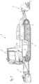
- zeigt eine Ausführungsform einer erfindungsgemäßen Pistenraupe in einer teilweise aufgeschnittenen, schematischen Seitenansicht,
- Fig. 2
- ein Blockschema der Fahr- und Arbeitsfunktionen der Pistenraupe gemäß
Fig. 1 und - Fig. 3
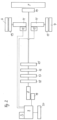
- ein Blockschema einer weiteren Ausführungsform einer erfindungsgemäßen Pistenraupe ähnlich den
Fig. 1 und2 . - Eine Pistenraupe 1 nach den
Fig. 1 und2 weist einen Fahrwerksrahmen 2 auf, an dessen gegenüberliegenden Längsseiten zwei Laufwerksseiten eines Kettenlaufwerks 3 angeordnet sind. Jede Laufwerksseite des Kettenlaufwerks 3 weist eine umlaufende Kette, ein frontseitiges Spannrad, mehrere an das frontseitige Spannrad in Fahrzeuglängsrichtung nach hinten anschließende und in einer Reihe hintereinander angeordnete Laufräder sowie rückseitig ein auch als Turasrad 4 bezeichnetes Triebrad auf. Die Kette ist im Bereich des frontseitigen Spannrads und des rückseitigen Turasrads 4 umgelenkt und läuft mit einem Obertrum oberhalb der Laufräder und mit einem Untertrum unterhalb der Laufräder entlang. - Heckseitig ist an dem Fahrwerksrahmen 2 ein hydraulisch verstellbarer Heckgeräteträger vorgesehen, der nicht näher bezeichnet ist. Der Heckgeräteträger trägt eine Heckfräse 7. Die Heckfräse 7 ist mit wenigstens einer rotierbaren Fräswelle und einer Finisheranordnung versehen, die den durch die Fräswelle zerkleinerten und aufgeworfenen Schneeuntergrund glättet.
- Frontseitig ist an einer frontseitigen Stirnseite des Fahrwerksrahmens 2 ein Räumschild 6 angelenkt. Das Räumschild 6 ist mithilfe von hydraulischen Stellmitteln verstellbar. In einer vorderen Hälfte des Fahrwerksrahmens 2 sitzt auf dem Fahrwerksrahmen 2 ein Fahrerhaus 5, in dem ein Fahrer Platz nimmt, um die Pistenraupe 1 bezüglich ihrer Fahr- und Arbeitsfunktionen zu steuern. Das Fahrerhaus 5 ist für Servicearbeiten aus der in
Fig. 1 dargestellten Betriebsstellung in eine Servicestellung nach vorne verkippbar um eine in Fahrzeugquerrichtung erstreckte Kippachse, die das Fahrerhaus 5 kippbeweglich am Fahrwerksrahmen 2 anlenkt. - Die Pistenraupe 1 weist ein Arbeitshydrauliksystem auf, das einen hydrostatischen Fräsmotor 14 für die Fräswelle der Heckfräse 7 sowie verschiedene hydraulische Arbeits- und Betriebsfunktionen der Pistenraupe 1 steuert. Zusätzlich zu dem als hydrostatischer Rotationsantrieb gestalteten Fräsmotor 14 sind eine hydrostatische Bremspumpe 18, eine hydrostatische Arbeitspumpe 17 und eine hydrostatische Lüfterpumpe 16 vorgesehen, die hydraulische Arbeits- und Betriebsfunktionen der Pistenraupe 1 speisen. Dem hydrostatischen Fräsmotor 14 ist eine hydrostatische Fräspumpe 15 zugeordnet, die entsprechend den hydraulischen Druck für den hydrostatischen Fräsmotor 14 aufbringt. Die genannten hydrostatischen Pumpen 15 bis 18 werden koaxial durch eine Antriebswelle eines Elektromotors 8 angetrieben. Die Arbeitspumpe 17 dient zum Aufbau eines hydrostatischen Drucks für Linearaktuatoren zum Verstellen des Räumschilds und/oder Linearaktuatoren zur Verstellung des Heckgeräteträgers. Die Lüfterpumpe 16 dient zur Erzeugung eines hydrostatischen Drucks für den Betrieb eines hydrostatischen Rotationsantriebs für ein Lüfterrad oder Ähnliches zur Belüftung und Kühlung elektrischer Funktionseinheiten der Pistenraupe 1, die nachfolgend näher beschrieben werden.
- Die Bremspumpe 18, die Arbeitspumpe 17, die Lüfterpumpe 16, die Fräspumpe 15 und der hydrostatische Fräsmotor 14 sind Teile des Arbeitshydrauliksystems der Pistenraupe 1.
- Ein Fahrantriebsystem für die Pistenraupe 1 weist zwei Elektromotoren 11 auf, die als Radnabenmotoren koaxial zu jeweils einem Turasrad 4 mittels jeweils eines Planetengetriebes 13 mechanisch mit dem jeweiligen Turasrad 4 verbunden sind, um dieses anzutreiben. Die beiden Elektromotoren 11 sind Synchronmotoren, die mittels jeweils eines Frequenzumrichters 12 durch Gleichstrom eines Batteriesystems 9 gespeist werden, das durch eine Vielzahl von wiederaufladbaren Akkumulatoren gebildet ist. Das Batteriesystem 9 ist im Fahrwerksrahmen 2 unterhalb des Fahrerhauses 5 untergebracht und dort lösbar befestigt, um das Batteriesystem 9 austauschen zu können. Das Batteriesystem 9 ist unterhalb des Fahrerhauses 5 relativ zum Fahrwerksrahmen 2 derart positioniert, dass das Batteriesystem 9 in der gekippten Servicestellung des Fahrerhauses 5 von oben her zugänglich ist, um entnommen werden zu können. Dadurch kann das Batteriesystem 9 in einfacher Weise durch ein neues Batteriesystem ersetzt werden.
- Das Arbeitshydrauliksystem wird durch einen Elektromotor 8 angetrieben, der die verschiedenen Pumpeinheiten rotatorisch antreibt und dadurch den gewünschten hydrostatischen Druck erzeugt. Dabei sind die verschiedenen Pumpeinheiten koaxial zu einer Antriebswelle des Elektromotors 8 angeordnet, um eine einfache Antriebsübertragung zu ermöglichen. Der Elektromotor 8 ist ebenfalls als Synchronmotor ausgebildet und wird durch das Batteriesystem 9 mit Strom versorgt. Ein Frequenzumrichter 19 dient auch bei dem Elektromotor 8 zur Umwandlung des Gleichstroms des Batteriesystems 9 in den für den Synchronmotor des Elektromotors 8 benötigten Wechselstrom.
- Sowohl der Elektromotor 8 als auch die beiden Elektromotoren 11 werden mit einer Betriebsspannung von 100 V betrieben.
- Den Elektromotoren 8 und 11 sowie dem Batteriesystem 9 ist eine elektronische Steuereinheit S zugeordnet, die eine Ansteuerung der Elektromotoren 8, 11 bewirkt und ein Batteriemanagementsystem umfasst, das eine gleichmäßige Auslastung der Vielzahl von Akkumulatoren innerhalb des Batteriesystems 9 gewährleistet. Ein dem Batteriesystem 9 zugeordneter Bremschopper 20 kann elektrische Energie aufnehmen, die von dem Batteriesystem 9 insbesondere bei Talfahrt der Pistenraupe 1 und einer entsprechenden Energierückspeisung nicht mehr aufgenommen werden kann.
- Um ein Aufladen des Batteriesystems 9 zu ermöglichen, ist an das Batteriesystem 9 ein Ladegerät 10 permanent angeschlossen, das an einer Rückwand des Fahrerhauses 5 fahrzeugfest angeordnet ist. Das Ladegerät 10 ist mit einem Spannungswandler versehen, um eine Aufladung des eine Batteriespannung von 100 V aufweisenden Batteriesystems 9 von einem gebäudeseitigen 380 V-Stromnetz bewirken zu können.
- Die Pistenraupe 1 weist demzufolge einen rein elektrischen Fahrantrieb auf, wobei die beiden Elektromotoren 11 direkt auf die Turasräder 4 beider Laufwerksseiten des Kettenlaufwerks 3 wirken. Zudem weist die Pistenraupe 1 hydrostatische Antriebe für die Heckfräse 7 einerseits und verschiedene Arbeits- und Betriebsfunktionen der Pistenraupe 1 andererseits auf, die über einen gemeinsamen Elektromotor 8 angetrieben werden.
- Eine Pistenraupe gemäß
Fig. 3 entspricht in Aufbau und Funktion bis auf die nachfolgend aufgeführten Unterschiede der Pistenraupe, wie sie zuvor unter Zuhilfenahme derFig. 1 und2 beschrieben wurde. Bei dem Blockschaltbild gemäßFig. 3 sind demzufolge funktionsgleiche Teile und Komponenten mit gleichen Bezugszeichen unter Hinzufügung des Buchstabens a versehen. Zur Vermeidung von Wiederholungen wird bezüglich bau- und funktionsgleicher Komponenten wie auch bezüglich des grundsätzlichen Aufbaus und der Funktion der Pistenraupe auf die anhand derFig. 1 und2 beschriebene Ausführungsform verwiesen. - Die Ausführungsform einer Pistenraupe gemäß
Fig. 3 weist einige wesentliche Unterschiede auf, die nachfolgend beschrieben sind. - Die Energieversorgung der verschiedenen Elektromotoren der Pistenraupe ist im Hochvoltbereich mit einer Betriebsspannung von 380 V/400 V vorgesehen.
- Das Batteriesystem 9a wird durch mehrere Batteriepakete B1 bis B3 gebildet. Die Batteriepakete B1 bis B3 sind durch eine elektrische Schaltung SB miteinander elektrisch verbunden. Die elektrische Schaltung SB ist in einem geschlossenen Gehäuse untergebracht. An die elektrische Schaltung SB ist sowohl ein Ladegerät 21 als auch ein Ladestecker 22 angeschlossen, wobei der Ladestecker 22 über ein flexibles Ladekabel mit dem Ladegerät verbunden ist. Der Ladestecker 22 kann bei Bedarf in eine Steckdose eines stationären Stromversorgungsnetzes eingesteckt werden. Dem Batteriesystem 9a ist analog der Ausführungsform nach
Fig. 2 eine elektronische Steuereinheit S zugeordnet, die ein Batteriemanagementsystem umfasst. Die Batteriepakete B1 und B2 sind beim dargestellten Ausführungsbeispiel mit vier Batterien und das Batteriepaket B3 mit acht Batterien versehen. - Durch den Betrieb der Elektromotoren 8a, 11, 26 im Hochvoltbereich mit 380 V/400 V umfasst die entsprechende Fahrzeugelektrik einen Hochvoltverteiler 24. An den Hochvoltverteiler 24 ist über einen Frequenzumrichter 19a zum einen der Elektromotor 8a angeschlossen, der das Arbeitshydrauliksystem betreibt. Das Arbeitshydrauliksystem umfasst eine hydrostatische Bremspumpe 18, eine hydrostatische Arbeitspumpe 17 und eine hydrostatische Lüfterpumpe 16, deren Funktionen den zuvor anhand der
Fig. 1 und2 bereits beschriebenen Funktionen entsprechen. - Ein weiterer wesentlicher Unterschied bei der Pistenraupe gemäß
Fig. 3 ist es, dass ein Elektromotor 26 zum Antreiben wenigstens einer Fräswelle der Heckfräse 7a direkt an der Heckfräse 7a montiert ist, so dass auch die Energieversorgung dieses Elektromotors 26 über einen Frequenzumrichter 25 mittels des bereits beschriebenen, im Hochvoltbereich betriebenen Batteriesystems erfolgt. Der Elektromotor 26 für die Heckfräse 7a ist mittels seines Frequenzumrichters 25 über eine elektrische Leitung mit dem Hochvoltverteiler 24 verbunden. Da die Heckfräse 7a lösbar an einem heckseitigen Geräteträger der Pistenraupe angeordnet ist, ist im Bereich des Geräteträgers eine Hochvoltsteckverbindung 23 vorgesehen, um den Elektromotor 26 für die Heckfräse 7a mit der Fahrzeugelektrik zu verbinden. Die Hochvoltsteckverbindung 23 weist zwei zueinander komplementäre und zusammensteckbare Steckverbindungsteile auf, von denen ein Steckverbindungsteil über ein flexibles Kabel dem Elektromotor 26 und das andere Steckverbindungsteil mit der fahrzeugseitigen Elektrik verbunden ist. Das letztgenannte Steckverbindungsteil ist im Bereich des Geräteträgers fest angeordnet. Bei einem Entfernen der Heckfräse 7a von der Pistenraupe kann somit in einfacher Weise die Hochvoltsteckverbindung 23 getrennt werden und die Heckfräse 7a vom Geräteträger gelöst werden. - Die elektrischen Fahrantriebe 11 bis 13 für die beiden Turasräder 4 des Kettenlaufwerks unterscheiden sich nicht von der Ausführungsform gemäß den
Fig. 1 und2 , so dass hierauf an dieser Stelle nicht näher eingegangen werden muss.
Claims (10)
- Pistenraupe (1) mit einem Kettenlaufwerk (3), das mittels eines Fahrantriebsystems antreibbar ist, wobei das Fahrantriebsystem zwei Elektromotoren (11) aufweist, die jeweils einem Turasrad (4) einer Laufwerksseite des Kettenlaufwerks (3) zugeordnet sind, dadurch gekennzeichnet, dass ein Arbeitshydrauliksystem vorgesehen ist, das wenigstens einen einer Arbeitsfunktion der Pistenraupe zugeordneten hydrostatischen Rotationsantrieb aufweist, wobei das Arbeitshydrauliksystem einen als hydrostatischer Rotationsantrieb gestalteten Fräsmotor (14) für eine Fräswelle einer Heckfräse (7) und eine hydrostatische Bremspumpe (18), eine hydrostatische Arbeitspumpe (17) und eine hydrostatische Lüfterpumpe (16) aufweist, wobei dem Fräsmotor (14) eine hydrostatische Fräspumpe (15) zugeordnet ist, die einen hydraulischen Druck für den Fräsmotor (14) aufbringt, wobei die Arbeitspumpe (17) zum Aufbau eines hydrostatischen Drucks für Linearaktuatoren zum Verstellen des Räumschilds und/oder für Linearaktuatoren zur Verstellung des Heckgeräteträgers dient, wobei die Lüfterpumpe (16) zur Erzeugung eines hydrostatischen Drucks für einen Betrieb eines hydrostatischen Rotationsantriebs für ein Lüfterrad zur Belüftung und Kühlung elektrischer Funktionseinheiten der Pistenraupe (1) dient, und dass das Arbeitshydrauliksystem durch wenigstens einen Elektromotor (8, 8a) angetrieben ist, der durch eine fahrzeugseitig montierte Energiequelle versorgt ist, sowie dass die hydrostatische Fräspumpe (15), die hydrostatische Lüfterpumpe (16), die hydrostatische Arbeitspumpe (17) und die hydrostatische Bremspumpe (18) koaxial durch eine Antriebswelle des Elektromotors (8) angetrieben sind.
- Pistenraupe nach Anspruch 1, dadurch gekennzeichnet, dass zur Energieversorgung des wenigstens einen Elektromotors (8, 8a, 11) ein wiederaufladbares Batteriesystem (9, 9a) vorgesehen ist.
- Pistenraupe nach Anspruch 2, dadurch gekennzeichnet, dass der Elektromotor (8, 8a) für das Arbeitshydrauliksystem als Synchronmotor gestaltet und - im Betrieb - mit einer Batteriespannung von 400 V oder 100 V versorgt wird.
- Pistenraupe nach Anspruch 1 oder 2, dadurch gekennzeichnet, dass die Elektromotoren (11) des Fahrantriebsystems als Synchronmotoren gestaltet und - im Betrieb - mit einer Batteriespannung von 400 V oder 100 V versorgt werden.
- Pistenraupe nach einem der vorhergehenden Ansprüche, dadurch gekennzeichnet, dass fahrzeugseitig ein Ladegerät (10, 21), insbesondere mit einem Ladestecker (22), vorgesehen ist.
- Pistenraupe nach Anspruch 5, dadurch gekennzeichnet, dass das Ladegerät (10) mit einem Spannungswandler versehen ist.
- Pistenraupe nach Anspruch 5 oder 6, dadurch gekennzeichnet, dass das Ladegerät (10, 21) und der Ladestecker (22) im Bereich einer Rückwand eines Fahrerhauses (5) angebracht ist.
- Pistenraupe nach Anspruch 2 oder 3, dadurch gekennzeichnet, dass das Batteriesystem (9, 9a) in einem Fahrwerksrahmen (2) unterhalb des Fahrerhauses (5) austauschbar untergebracht ist.
- Pistenraupe nach Anspruch 2 oder 3, dadurch gekennzeichnet, dass das Batteriesystem (9a) mehrere Batteriepakete (B1 bis B3) aufweist, die jeweils mittels einer elektrischen Steckverbindung (23) schnellwechselbar miteinander sowie mit dem wenigstens einen Elektromotor (26) verbunden sind.
- Pistenraupe nach Anspruch 9, dadurch gekennzeichnet, dass den Batteriepaketen (B1 bis B3) eine elektrische Schaltung (SB) zugeordnet ist, die die Batteriepakete (B1 bis B3) elektrisch miteinander sowie mit weiteren elektrischen oder elektronischen Bauteilkomponenten der Fahrzeugelektrik und insbesondere der Elektromotoren (8a, 11, 26) koppelt.
Priority Applications (3)
| Application Number | Priority Date | Filing Date | Title |
|---|---|---|---|
| EP24207387.2A EP4516560A1 (de) | 2018-08-07 | 2019-07-04 | Pistenraupe mit einer seilwinde und mit einem kettenlaufwerk |
| EP24207386.4A EP4470889A3 (de) | 2018-08-07 | 2019-07-04 | Pistenraupe mit einer heckfräse und einem kettenlaufwerk |
| EP25193073.1A EP4636161A3 (de) | 2018-08-07 | 2019-07-04 | Pistenraupe mit einer heckfräse und einem kettenlaufwerk |
Applications Claiming Priority (1)
| Application Number | Priority Date | Filing Date | Title |
|---|---|---|---|
| DE102018213240.2A DE102018213240A1 (de) | 2018-08-07 | 2018-08-07 | Pistenraupe mit einem Kettenlaufwerk |
Related Child Applications (5)
| Application Number | Title | Priority Date | Filing Date |
|---|---|---|---|
| EP25193073.1A Division EP4636161A3 (de) | 2018-08-07 | 2019-07-04 | Pistenraupe mit einer heckfräse und einem kettenlaufwerk |
| EP24207386.4A Division-Into EP4470889A3 (de) | 2018-08-07 | 2019-07-04 | Pistenraupe mit einer heckfräse und einem kettenlaufwerk |
| EP24207386.4A Division EP4470889A3 (de) | 2018-08-07 | 2019-07-04 | Pistenraupe mit einer heckfräse und einem kettenlaufwerk |
| EP24207387.2A Division-Into EP4516560A1 (de) | 2018-08-07 | 2019-07-04 | Pistenraupe mit einer seilwinde und mit einem kettenlaufwerk |
| EP24207387.2A Division EP4516560A1 (de) | 2018-08-07 | 2019-07-04 | Pistenraupe mit einer seilwinde und mit einem kettenlaufwerk |
Publications (2)
| Publication Number | Publication Date |
|---|---|
| EP3608151A1 EP3608151A1 (de) | 2020-02-12 |
| EP3608151B1 true EP3608151B1 (de) | 2025-04-16 |
Family
ID=67180585
Family Applications (4)
| Application Number | Title | Priority Date | Filing Date |
|---|---|---|---|
| EP25193073.1A Pending EP4636161A3 (de) | 2018-08-07 | 2019-07-04 | Pistenraupe mit einer heckfräse und einem kettenlaufwerk |
| EP24207386.4A Pending EP4470889A3 (de) | 2018-08-07 | 2019-07-04 | Pistenraupe mit einer heckfräse und einem kettenlaufwerk |
| EP19184295.4A Active EP3608151B1 (de) | 2018-08-07 | 2019-07-04 | Pistenraupe mit einem kettenlaufwerk |
| EP24207387.2A Pending EP4516560A1 (de) | 2018-08-07 | 2019-07-04 | Pistenraupe mit einer seilwinde und mit einem kettenlaufwerk |
Family Applications Before (2)
| Application Number | Title | Priority Date | Filing Date |
|---|---|---|---|
| EP25193073.1A Pending EP4636161A3 (de) | 2018-08-07 | 2019-07-04 | Pistenraupe mit einer heckfräse und einem kettenlaufwerk |
| EP24207386.4A Pending EP4470889A3 (de) | 2018-08-07 | 2019-07-04 | Pistenraupe mit einer heckfräse und einem kettenlaufwerk |
Family Applications After (1)
| Application Number | Title | Priority Date | Filing Date |
|---|---|---|---|
| EP24207387.2A Pending EP4516560A1 (de) | 2018-08-07 | 2019-07-04 | Pistenraupe mit einer seilwinde und mit einem kettenlaufwerk |
Country Status (2)
| Country | Link |
|---|---|
| EP (4) | EP4636161A3 (de) |
| DE (1) | DE102018213240A1 (de) |
Families Citing this family (3)
| Publication number | Priority date | Publication date | Assignee | Title |
|---|---|---|---|---|
| DE102021200268A1 (de) | 2021-01-13 | 2022-07-14 | Kässbohrer Geländefahrzeug Aktiengesellschaft | Pistenpflegefahrzeug |
| DE102021202819A1 (de) * | 2021-03-23 | 2022-09-29 | Kässbohrer Geländefahrzeug Aktiengesellschaft | Pistenraupe und Verfahren zum Steuern der Stromversorgung einer Pistenraupe |
| DE102022203857A1 (de) | 2022-04-20 | 2023-10-26 | Kässbohrer Geländefahrzeug Aktiengesellschaft | Pistenraupe zur Gestaltung und Pflege von Schneegelände |
Citations (1)
| Publication number | Priority date | Publication date | Assignee | Title |
|---|---|---|---|---|
| EP1245736A2 (de) * | 2001-03-30 | 2002-10-02 | Prinoth GmbH-S.r.l. | Pistenpflegefahrzeug mit Schwenkbar angebauter Fräse |
Family Cites Families (9)
| Publication number | Priority date | Publication date | Assignee | Title |
|---|---|---|---|---|
| US5363937A (en) | 1992-10-19 | 1994-11-15 | Lmc Operating Corp. | Battery operated tracked vehicle |
| DE29607651U1 (de) * | 1996-04-26 | 1997-08-28 | Kässbohrer Geländefahrzeug AG, 89250 Senden | Kettenfahrzeug |
| DE10333594A1 (de) * | 2003-07-24 | 2005-02-17 | Linde Ag | Batteriewechsel-System für ein batterie-elektrisch betriebenes Flurförderzeug |
| DE102009047065A1 (de) * | 2009-11-24 | 2011-05-26 | SB LiMotive Company Ltd., Suwon | Serienschaltung von Schaltreglern zur Energieübertragung in Batteriesystemen |
| DE102010049984A1 (de) * | 2010-10-19 | 2012-04-19 | Kässbohrer Geländefahrzeug AG | Verfahren zur Steuerung einer Seilwinde eines Kettenfahrzeugs und Pistenraupe |
| DE102010043511A1 (de) * | 2010-11-05 | 2012-05-10 | Kässbohrer Geländefahrzeug AG | Pistenraupe |
| DE102011087711A1 (de) * | 2011-12-05 | 2013-06-06 | Zf Friedrichshafen Ag | Hybrid- oder Elektrofahrzeug |
| DE202013004087U1 (de) * | 2012-05-29 | 2013-05-27 | Kässbohrer Geländefahrzeug AG | Pistenraupe |
| EP3546652B1 (de) * | 2013-12-11 | 2021-06-23 | Prinoth Ltd. | Pedalsystem für pistenraupe |
-
2018
- 2018-08-07 DE DE102018213240.2A patent/DE102018213240A1/de active Pending
-
2019
- 2019-07-04 EP EP25193073.1A patent/EP4636161A3/de active Pending
- 2019-07-04 EP EP24207386.4A patent/EP4470889A3/de active Pending
- 2019-07-04 EP EP19184295.4A patent/EP3608151B1/de active Active
- 2019-07-04 EP EP24207387.2A patent/EP4516560A1/de active Pending
Patent Citations (1)
| Publication number | Priority date | Publication date | Assignee | Title |
|---|---|---|---|---|
| EP1245736A2 (de) * | 2001-03-30 | 2002-10-02 | Prinoth GmbH-S.r.l. | Pistenpflegefahrzeug mit Schwenkbar angebauter Fräse |
Also Published As
| Publication number | Publication date |
|---|---|
| EP4636161A3 (de) | 2025-11-12 |
| EP4636161A2 (de) | 2025-10-22 |
| EP3608151A1 (de) | 2020-02-12 |
| EP4516560A1 (de) | 2025-03-05 |
| EP4470889A3 (de) | 2025-03-05 |
| DE102018213240A1 (de) | 2020-02-13 |
| EP4470889A2 (de) | 2024-12-04 |
Similar Documents
| Publication | Publication Date | Title |
|---|---|---|
| EP3608151B1 (de) | Pistenraupe mit einem kettenlaufwerk | |
| EP0895495B1 (de) | Kettengetriebenes pistenpflegefahrzeug | |
| DE102010010578B4 (de) | Hydrostatisch-elektrischer Antrieb, Flurförderfahrzeug mit einem solchen Antrieb | |
| DE202014000738U1 (de) | Radlader mit Energiespeichereinheit | |
| DE112012001408T5 (de) | Elektroarbeitsfahrzeug und Batteriehaltekonstruktion desselben | |
| DE60031545T2 (de) | Schaufel | |
| EP0628661B1 (de) | Strassenfertiger | |
| DE102014011195B4 (de) | Bodenfräsmaschine mit von einem Wartungsmotor betriebenem Kompressor und Verfahren zum Betrieb einer solchen Bodenfräsmaschine | |
| EP0489969A1 (de) | Fertiger | |
| EP4396013B1 (de) | Leistungsstranganordnung einer arbeitsmaschine und arbeitsmaschine | |
| EP4491433A2 (de) | Pistenraupe mit einem kettenlaufwerk | |
| DE202013004087U1 (de) | Pistenraupe | |
| EP2684772A2 (de) | Kettenfahrzeug mit einem zentralen Antriebsmotor | |
| DE202020107068U1 (de) | Arbeitsfahrzeug | |
| EP1118714B2 (de) | Strassenfertiger | |
| EP4344926B1 (de) | Arbeitsmaschine mit elektrischem fahrantrieb | |
| DE2602898A1 (de) | Universal-arbeitsmaschine | |
| EP3469872B1 (de) | Arbeitsgerät, arbeitsfahrzeug mit einem solchen arbeitsgerät, baukasten zum herstellen des arbeitsgerätes sowie verfahren zum betreiben wenigstens des arbeitsgerätes | |
| EP1391370A1 (de) | Selbstfahrende, lenkbare Arbeitsmaschine | |
| DE102004018588A1 (de) | Arbeitsmaschine mit Eigenantrieb zum Hinterhergehen | |
| EP0286878B1 (de) | Universalarbeitsfahrzeug | |
| EP4269151A1 (de) | Pistenraupe zur gestaltung und pflege von schneegelände | |
| DE2829124C2 (de) | ||
| EP4360421A2 (de) | Anbaugerät | |
| DE102024117762A1 (de) | Mobilisiereinrichtung |
Legal Events
| Date | Code | Title | Description |
|---|---|---|---|
| PUAI | Public reference made under article 153(3) epc to a published international application that has entered the european phase |
Free format text: ORIGINAL CODE: 0009012 |
|
| STAA | Information on the status of an ep patent application or granted ep patent |
Free format text: STATUS: THE APPLICATION HAS BEEN PUBLISHED |
|
| AK | Designated contracting states |
Kind code of ref document: A1 Designated state(s): AL AT BE BG CH CY CZ DE DK EE ES FI FR GB GR HR HU IE IS IT LI LT LU LV MC MK MT NL NO PL PT RO RS SE SI SK SM TR |
|
| AX | Request for extension of the european patent |
Extension state: BA ME |
|
| STAA | Information on the status of an ep patent application or granted ep patent |
Free format text: STATUS: REQUEST FOR EXAMINATION WAS MADE |
|
| 17P | Request for examination filed |
Effective date: 20200708 |
|
| RBV | Designated contracting states (corrected) |
Designated state(s): AL AT BE BG CH CY CZ DE DK EE ES FI FR GB GR HR HU IE IS IT LI LT LU LV MC MK MT NL NO PL PT RO RS SE SI SK SM TR |
|
| STAA | Information on the status of an ep patent application or granted ep patent |
Free format text: STATUS: EXAMINATION IS IN PROGRESS |
|
| 17Q | First examination report despatched |
Effective date: 20210922 |
|
| GRAP | Despatch of communication of intention to grant a patent |
Free format text: ORIGINAL CODE: EPIDOSNIGR1 |
|
| STAA | Information on the status of an ep patent application or granted ep patent |
Free format text: STATUS: GRANT OF PATENT IS INTENDED |
|
| INTG | Intention to grant announced |
Effective date: 20241223 |
|
| GRAS | Grant fee paid |
Free format text: ORIGINAL CODE: EPIDOSNIGR3 |
|
| GRAA | (expected) grant |
Free format text: ORIGINAL CODE: 0009210 |
|
| STAA | Information on the status of an ep patent application or granted ep patent |
Free format text: STATUS: THE PATENT HAS BEEN GRANTED |
|
| AK | Designated contracting states |
Kind code of ref document: B1 Designated state(s): AL AT BE BG CH CY CZ DE DK EE ES FI FR GB GR HR HU IE IS IT LI LT LU LV MC MK MT NL NO PL PT RO RS SE SI SK SM TR |
|
| REG | Reference to a national code |
Ref country code: GB Ref legal event code: FG4D Free format text: NOT ENGLISH |
|
| P01 | Opt-out of the competence of the unified patent court (upc) registered |
Free format text: CASE NUMBER: APP_14063/2025 Effective date: 20250321 |
|
| REG | Reference to a national code |
Ref country code: CH Ref legal event code: EP Ref country code: DE Ref legal event code: R096 Ref document number: 502019013205 Country of ref document: DE |
|
| REG | Reference to a national code |
Ref country code: IE Ref legal event code: FG4D Free format text: LANGUAGE OF EP DOCUMENT: GERMAN |
|
| REG | Reference to a national code |
Ref country code: NL Ref legal event code: MP Effective date: 20250416 |
|
| PG25 | Lapsed in a contracting state [announced via postgrant information from national office to epo] |
Ref country code: NL Free format text: LAPSE BECAUSE OF FAILURE TO SUBMIT A TRANSLATION OF THE DESCRIPTION OR TO PAY THE FEE WITHIN THE PRESCRIBED TIME-LIMIT Effective date: 20250416 |
|
| PG25 | Lapsed in a contracting state [announced via postgrant information from national office to epo] |
Ref country code: PT Free format text: LAPSE BECAUSE OF FAILURE TO SUBMIT A TRANSLATION OF THE DESCRIPTION OR TO PAY THE FEE WITHIN THE PRESCRIBED TIME-LIMIT Effective date: 20250818 Ref country code: ES Free format text: LAPSE BECAUSE OF FAILURE TO SUBMIT A TRANSLATION OF THE DESCRIPTION OR TO PAY THE FEE WITHIN THE PRESCRIBED TIME-LIMIT Effective date: 20250416 Ref country code: FI Free format text: LAPSE BECAUSE OF FAILURE TO SUBMIT A TRANSLATION OF THE DESCRIPTION OR TO PAY THE FEE WITHIN THE PRESCRIBED TIME-LIMIT Effective date: 20250416 |
|
| PGFP | Annual fee paid to national office [announced via postgrant information from national office to epo] |
Ref country code: DE Payment date: 20250723 Year of fee payment: 7 |
|
| REG | Reference to a national code |
Ref country code: LT Ref legal event code: MG9D |
|
| PG25 | Lapsed in a contracting state [announced via postgrant information from national office to epo] |
Ref country code: NO Free format text: LAPSE BECAUSE OF FAILURE TO SUBMIT A TRANSLATION OF THE DESCRIPTION OR TO PAY THE FEE WITHIN THE PRESCRIBED TIME-LIMIT Effective date: 20250716 Ref country code: GR Free format text: LAPSE BECAUSE OF FAILURE TO SUBMIT A TRANSLATION OF THE DESCRIPTION OR TO PAY THE FEE WITHIN THE PRESCRIBED TIME-LIMIT Effective date: 20250717 |
|
| PG25 | Lapsed in a contracting state [announced via postgrant information from national office to epo] |
Ref country code: PL Free format text: LAPSE BECAUSE OF FAILURE TO SUBMIT A TRANSLATION OF THE DESCRIPTION OR TO PAY THE FEE WITHIN THE PRESCRIBED TIME-LIMIT Effective date: 20250416 |
|
| PGFP | Annual fee paid to national office [announced via postgrant information from national office to epo] |
Ref country code: IT Payment date: 20250808 Year of fee payment: 7 |
|
| PG25 | Lapsed in a contracting state [announced via postgrant information from national office to epo] |
Ref country code: BG Free format text: LAPSE BECAUSE OF FAILURE TO SUBMIT A TRANSLATION OF THE DESCRIPTION OR TO PAY THE FEE WITHIN THE PRESCRIBED TIME-LIMIT Effective date: 20250416 |
|
| PG25 | Lapsed in a contracting state [announced via postgrant information from national office to epo] |
Ref country code: HR Free format text: LAPSE BECAUSE OF FAILURE TO SUBMIT A TRANSLATION OF THE DESCRIPTION OR TO PAY THE FEE WITHIN THE PRESCRIBED TIME-LIMIT Effective date: 20250416 |
|
| PGFP | Annual fee paid to national office [announced via postgrant information from national office to epo] |
Ref country code: FR Payment date: 20250723 Year of fee payment: 7 Ref country code: AT Payment date: 20250721 Year of fee payment: 7 |
|
| PGFP | Annual fee paid to national office [announced via postgrant information from national office to epo] |
Ref country code: CH Payment date: 20250801 Year of fee payment: 7 |
|
| PG25 | Lapsed in a contracting state [announced via postgrant information from national office to epo] |
Ref country code: RS Free format text: LAPSE BECAUSE OF FAILURE TO SUBMIT A TRANSLATION OF THE DESCRIPTION OR TO PAY THE FEE WITHIN THE PRESCRIBED TIME-LIMIT Effective date: 20250716 |
|
| PG25 | Lapsed in a contracting state [announced via postgrant information from national office to epo] |
Ref country code: IS Free format text: LAPSE BECAUSE OF FAILURE TO SUBMIT A TRANSLATION OF THE DESCRIPTION OR TO PAY THE FEE WITHIN THE PRESCRIBED TIME-LIMIT Effective date: 20250816 |
|
| PG25 | Lapsed in a contracting state [announced via postgrant information from national office to epo] |
Ref country code: LV Free format text: LAPSE BECAUSE OF FAILURE TO SUBMIT A TRANSLATION OF THE DESCRIPTION OR TO PAY THE FEE WITHIN THE PRESCRIBED TIME-LIMIT Effective date: 20250416 |
|
| PG25 | Lapsed in a contracting state [announced via postgrant information from national office to epo] |
Ref country code: SM Free format text: LAPSE BECAUSE OF FAILURE TO SUBMIT A TRANSLATION OF THE DESCRIPTION OR TO PAY THE FEE WITHIN THE PRESCRIBED TIME-LIMIT Effective date: 20250416 Ref country code: DK Free format text: LAPSE BECAUSE OF FAILURE TO SUBMIT A TRANSLATION OF THE DESCRIPTION OR TO PAY THE FEE WITHIN THE PRESCRIBED TIME-LIMIT Effective date: 20250416 |
|
| PG25 | Lapsed in a contracting state [announced via postgrant information from national office to epo] |
Ref country code: CZ Free format text: LAPSE BECAUSE OF FAILURE TO SUBMIT A TRANSLATION OF THE DESCRIPTION OR TO PAY THE FEE WITHIN THE PRESCRIBED TIME-LIMIT Effective date: 20250416 |
|
| PG25 | Lapsed in a contracting state [announced via postgrant information from national office to epo] |
Ref country code: EE Free format text: LAPSE BECAUSE OF FAILURE TO SUBMIT A TRANSLATION OF THE DESCRIPTION OR TO PAY THE FEE WITHIN THE PRESCRIBED TIME-LIMIT Effective date: 20250416 |
|
| PG25 | Lapsed in a contracting state [announced via postgrant information from national office to epo] |
Ref country code: RO Free format text: LAPSE BECAUSE OF FAILURE TO SUBMIT A TRANSLATION OF THE DESCRIPTION OR TO PAY THE FEE WITHIN THE PRESCRIBED TIME-LIMIT Effective date: 20250416 Ref country code: SK Free format text: LAPSE BECAUSE OF FAILURE TO SUBMIT A TRANSLATION OF THE DESCRIPTION OR TO PAY THE FEE WITHIN THE PRESCRIBED TIME-LIMIT Effective date: 20250416 |