EP3608046B1 - Hole cutter with axially-elongated aperture defining multiple fulcrums - Google Patents
Hole cutter with axially-elongated aperture defining multiple fulcrums Download PDFInfo
- Publication number
- EP3608046B1 EP3608046B1 EP19201282.1A EP19201282A EP3608046B1 EP 3608046 B1 EP3608046 B1 EP 3608046B1 EP 19201282 A EP19201282 A EP 19201282A EP 3608046 B1 EP3608046 B1 EP 3608046B1
- Authority
- EP
- European Patent Office
- Prior art keywords
- fulcrum
- hole cutter
- axially
- cutting edge
- blade body
- Prior art date
- Legal status (The legal status is an assumption and is not a legal conclusion. Google has not performed a legal analysis and makes no representation as to the accuracy of the status listed.)
- Active
Links
Images
Classifications
-
- B—PERFORMING OPERATIONS; TRANSPORTING
- B23—MACHINE TOOLS; METAL-WORKING NOT OTHERWISE PROVIDED FOR
- B23B—TURNING; BORING
- B23B51/00—Tools for drilling machines
- B23B51/04—Drills for trepanning
- B23B51/0453—Drills for trepanning with ejecting devices
-
- B—PERFORMING OPERATIONS; TRANSPORTING
- B23—MACHINE TOOLS; METAL-WORKING NOT OTHERWISE PROVIDED FOR
- B23B—TURNING; BORING
- B23B51/00—Tools for drilling machines
- B23B51/04—Drills for trepanning
- B23B51/0467—Details of the tubular body sidewall
-
- B—PERFORMING OPERATIONS; TRANSPORTING
- B23—MACHINE TOOLS; METAL-WORKING NOT OTHERWISE PROVIDED FOR
- B23B—TURNING; BORING
- B23B51/00—Tools for drilling machines
- B23B51/04—Drills for trepanning
-
- Y—GENERAL TAGGING OF NEW TECHNOLOGICAL DEVELOPMENTS; GENERAL TAGGING OF CROSS-SECTIONAL TECHNOLOGIES SPANNING OVER SEVERAL SECTIONS OF THE IPC; TECHNICAL SUBJECTS COVERED BY FORMER USPC CROSS-REFERENCE ART COLLECTIONS [XRACs] AND DIGESTS
- Y10—TECHNICAL SUBJECTS COVERED BY FORMER USPC
- Y10T—TECHNICAL SUBJECTS COVERED BY FORMER US CLASSIFICATION
- Y10T408/00—Cutting by use of rotating axially moving tool
- Y10T408/89—Tool or Tool with support
- Y10T408/895—Having axial, core-receiving central portion
Definitions
- the present invention relates to a hole cutter according to the preamble of claim 1, and more particularly, to hole cutters with apertures in their side walls that define fulcrums for inserting and levering a tool, such as a screwdriver, to remove work piece slugs from the interiors of the hole cutters.
- a hole cutter is known from US 5 205 685 A .
- a hole cutter or hole saw, is a type of cutter used in drilling circular holes in various materials, such as wood, metal, drywall, etc.
- a hole cutter typically has a substantially cylindrical body that defines a side wall, a circular cutting edge with teeth located at one end of the body and designed to cut a work piece during rotation of the cutter, and a cap located at the end of the body opposite the cutting edge.
- the cap typically includes threads, holes or other structure adapted to allow the hole cutter to be drivingly connected to a drill, such as through an arbor.
- the circular cutting edge creates a circular hole in a work piece and, in turn, removes a circular work piece slug therefrom.
- the work piece slug is retained within the hollow interior of the hole cutter and must be removed therefrom prior to cutting another hole.
- Prior art hole cutters include apertures or slots formed in the side walls of the hole cutters that allow users to insert a lever, such as a screwdriver, through the side wall and into the interior of the hole cutter to, in turn, lever or otherwise urge the slug out of the hole cutter.
- This manual slug removal task can be time-consuming and take substantial effort on the part of the user.
- a slug may be difficult to extract from within the body of a cutter, even with a hole cutter that includes slug removal apertures or slots, because the slug can become tightly wedged in the cutter or because the slug removal apertures or slots are not aligned with the slug. For example, a slug may become warped or cracked and thus firmly lodged within the hole cutter.
- some work pieces such as woods, contain sticky or glue-like residue that inhibits slug removal.
- thicker and thinner work pieces will create slugs of differing thicknesses and slugs positioned at different locations within the hole cutter.
- a thick work piece can create a thick slug that is pushed deep into the body of the hole cutter, whereas a thin work piece can create a thin slug located near the cutting edge. Accordingly, slugs often do not simply "pop" out of the cutter when worked by a tool. Slugs often slide short distances, twist, tilt or otherwise gradually or incrementally move along the inside of the cutter.
- One advantage of the hole cutters of the present invention is that they can provide a relatively quick, easy, and effective means to extract slugs from inside the hole cutters. Another advantage of the hole cutters of the present invention is that they provide multiple fulcrums at different axial locations, and in some embodiments, angular locations, to facilitate aligning the fulcrums with a variety of work piece slugs of different thicknesses. Yet another advantage of the hole cutters of the present invention is that they provide multiple fulcrums within the same axially-elongated aperture and thereby allow a user to work a slug out of the cutter by using multiple fulcrums without removing the lever, such as a screwdriver, from the aperture.
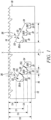
- a blade body of a hole cutter embodying the present invention is indicated generally by the reference numeral 10.
- the term "hole cutter” is used here to mean a tool that cuts holes in work pieces, such as wood or metal work pieces, and includes without limitation hole saws.
- the blade body 10 is shown in FIG. 1 in its flattened state; however, as will be recognized by those of ordinary skill in the pertinent art based on the teachings herein, the blade body 10 is rolled or otherwise formed into a substantially cylindrical shape to form the hole cutter.
- the blade body 10 comprises a side wall 12 that extends around an axis of rotation "X" of the hole cutter to define a substantially cylindrical blade body.
- One end of the blade body is provided with a cutting edge 14 oriented substantially perpendicular to the axis of rotation X, and the opposing end of the blade body defines a rim 16.
- a cap (not shown) is fixedly secured to the rim 16 to enclose the respective end of the hole cutter.
- the end of the hole cutter opposite the cutting edge 14 and including the rim 16 and a cap (not shown) attached thereto is referred to herein as the "non-working" end of the hole cutter.
- the cap (not shown) may include a threaded hub and pin apertures so that the hole cutter can be coupled to, and driven by, an arbor drivingly connected to a power tool, such as an electric drill. As shown in FIG.
- the cutting edge 14 is defined by a plurality of teeth with gullets extending between the teeth.
- the cutting edge may be defined by any of numerous different tooth forms or other cutting edge forms that are currently known or that later become known.
- the blade body 10 is formed from sheet metal that is rolled or otherwise formed into the cylindrical blade body 10 of the hole cutter and is, in turn, welded or otherwise attached to a cap, the hole cutter may be formed in any of numerous other ways that are currently known, or that later become known.
- the end cap and side wall 12 may be spun, drawn, molded or otherwise formed in one part.
- the blade body 10 defines two axially-elongated apertures or slots 18 formed through the side wall 12 thereof.
- the two slots 18 are angularly spaced relative to each other on the cylindrical blade body 10.
- the two slots 18 are approximately equally spaced relative to each other, i.e., the two slots are spaced about 180° relative to each other.
- each slot 18 has an axial depth D5 (D4-D2) ranging from about 29 mm to about 46 mm ( 1-1/8 inches to about 1-4/5 inches).
- each slot 18 has an axial depth D5 of about 34 mm (1-1/3 inches).
- the number of axially-elongated apertures or slots 18 formed through the side wall 12 of the hole cutter depends on the size of the hole cutter. As a general rule, the larger the diameter of the hole cutter, the greater is the number of axially-elongated apertures or slots 18 that can be formed through the cylindrical blade body 10.
- relatively small diameter hole cutters e.g., about 14 mm (9/16 inch) diameter to about 21 mm (13/16 inch) diameter
- larger diameter hole cutters have two slots 18 (e.g., about 22 mm (7/8 inch) diameter to about 37 mm (1-7/16 inches) diameter) oriented substantially parallel to the axis X of the hole cutter
- still larger diameter hole cutters e.g., about 38 mm (1 -1/2 inches) diameter to about 86 mm (3-3/8 inches) diameter
- still larger diameter hole cutters e.g., about 89 mm (3-1/2 inches) diameter to about 150 mm (6 inches) diameter
- four larger area slots 18 oriented at acute angles relative to the axis X of the hole cutter.
- the axially-extending slots 18 are approximately equally spaced relative to each other about the axis X of the hole cutter, i.e., if there are two axially-extending slots 18 they are angularly spaced about 180° relative to each other, if there are three axially- extending slots 18 they are angularly spaced about 120° relative to each other, if there are four axially-extending slots 18 they are angularly spaced about 90° relative to each other, etc.
- the axially-extending apertures or slots 18 need not be equally spaced relative to each other, nor do all axially-elongated apertures or slots 18 on the same hole cutter need to define the same aperture area or slot configuration.
- each axially-elongated aperture or slot 18 includes three fulcrums 20A, 20B and 20C axially and angularly spaced relative to each other.
- the slot 18 may include fewer than three fulcrums, or more than three fulcrums.
- the fulcrums 20A, 20B and 20C are recessed edge surfaces of the side wall 12 of the blade body 10 that are formed on the edge of a respective axially-extending aperture or slot 18 that is adjacent to, or on the side of, the non- working end of the hole cutter.
- the fulcrums 20A, 20B and 20C extend linearly in a direction substantially perpendicular to the axis of rotation X of the hole cutter or substantially parallel to the cutting edge 14. Accordingly, a common tool, such as a screw driver, can be inserted into the axially-extending aperture or slot 18, slipped into engagement with a respective fulcrum 20A, 20B or 20C, and manipulated as a lever against the respective fulcrum 20A, 20B or 20C to pry or push a slug out of the interior of the blade body 10.
- a common tool such as a screw driver
- Each fulcrum 20A, 20B and 20C defines a width W1 that is sufficient to support a common tool or implement, such as the elongate shaft of an ordinary screw driver, e.g., a number 2 screw driver.
- the recess of each fulcrum 20A, 20B and 20C defines a width W1 that is least about 6.4 mm (1/4 inch) to allow insertion therein of a number 2 screw driver (which requires a width or clearance of about 6.9 mm (0.27 inch)), and preferably is within the range of about 6.4 mm to about 8.5 mm (1/4 inch to about 1/3 inch).
- each fulcrum 20A, 20B, and 20C is oriented substantially parallel to the cutting edge 14, and is located on the side of the axially-extending aperture or slot 18 opposite the cutting edge 14.
- each fulcrum 20A, 20B and 20C is recessed within the respective side edge of the axially-extending aperture or slot 18 so that a side edge or lip 21 is formed at either end of the fulcrum 20A, 20B and 20C to facilitate retaining a tool within the fulcrum 20A, 20B and 20C when levered against it.
- each lip or fulcrum side edge 21 is oriented substantially normal to the cutting edge 14 or substantially parallel to the axis of rotation X of the hole cutter.
- each fulcrum 20A, 20B and 20C facilitates engagement of the fulcrum 20A, 20B and 20C by a tool and levering of the tool against the fulcrum 20A, 20B and 20C to pry or otherwise move a work piece slug out of the interior of the blade body 10.
- Forming at least a portion of the fulcrum surface 20A, 20B and 20C substantially parallel to the cutting edge 14, and on the side of the axially-extending aperture or slot 18 opposite the cutting edge 14, facilitates in levering the tool against the side of the slug opposite the cutting edge 14 to force the slug out of the interior of the blade body 10.
- each slot 18 further defines a side edge 23 that is spaced opposite the fulcrums 20A, 20B and 20C by a minimum width W2 of the respective axially-extending slot 18 that is sufficient to allow a common tool, such as a number 2 screwdriver, to slide axially through the axially-extending slot 18 from one fulcrum 20A, 20B or 20C to another.
- the minimum width W2 is preferably at least about 6.4 mm (1/4 inch), is more preferably within the range of about 1/4 inch to about 1/3 inch, and in the illustrated embodiment, is about 6.9 mm (0.27 inch).
- each axially-extending slot 18 is substantially smooth and rectilinear to facilitate sliding movement of a tool into and through the axially-extending slot 18 (e.g., from one fulcrum 20A, 20B or 20C to another to progressively remove a slug) and to facilitate chip and/or dust egress through the axially-extending slot 18.
- each fulcrum 20A, 20B and 20C and axially-elongated aperture or slot 18 are only exemplary, and any of numerous other configurations, orientations, locations and/or dimensions that are currently known, or that later become known, equally may be employed.
- the first fulcrum 20A is axially spaced adjacent to the cutting edge 14
- the second fulcrum 20C is axially spaced further from the cutting edge 14 as compared to the first fulcrum 20A and adjacent to the rim 16 or non- working end of the hole cutter
- the third fulcrum 20B is axially spaced between the first and second fulcrums 20A and 20C.
- the first fulcrum 20A is located at approximately one end of the axially- elongated aperture or slot 18
- the second fulcrum 20C is located at approximately an opposite end of the aperture or slot 18 relative to the first fulcrum 20A
- the third fulcrum 20B is located approximately midway between the first fulcrum 20 A and the second fulcrum 20C.
- the first fulcrum 20A is axially spaced from the cutting edge 14 a first distance DI within the range of about 13 mm to about 25 mm ( 1/2 inch to about 1 inch)
- the second fulcrum 20C is angularly spaced relative to the first fulcrum 20A and is axially spaced from the cutting edge 14 a second distance D2 within the range of about 38 mm to about 51 mm (1-1/2 inches to about 2 inches)
- the third fulcrum 20B is angularly and axially spaced between the first and second fulcrums 20A and 20C and is axially spaced from the cutting edge 14 a third distance D3 within the range of about 25 mm to about 38 mm ( inch to about 1-1/2 inches).
- the first distance DI of the first fulcrum 20A is configured for levering slugs having thicknesses of about 13 mm (1/2 inch) or less
- the third distance D3 of the third fulcrum 20B is configured for levering slugs having thicknesses of about 1 inch or less (e.g., a 3/4 inch thick plywood slug)
- the second distance D2 of the second fulcrum 20C is configured for levering slugs having thicknesses of about 38 mm (1-1/2 inches) or less (e.g., a 2 x 4 slug).
- the distances DI, D2 and D3 are measured from a plane defined by the cutting edge 14, such as a plane extending between the tips of unset teeth.
- the distances between the fulcrums 20A, 20B and 20C and the cutting edge 14, or between other features of the hole cutter and the cutting edge 14, may be measured with respect to any of numerous other reference lines or features that are currently known or used, or that later become known or used, such as from the base of the deepest gullets of the cutting edge teeth.
- a user may insert a tool through one of the axially-extending slots 18, place the tip of the tool in contact with the side of the slug facing the cap (not shown) or the interior of the blade body 10, select the second fulcrum 20C located axially furthest from the cutting edge 14 by placing a distal part of the tool into contact with the fulcrum 20C, and apply a force to a proximate portion of the tool to use the tool and the fulcrum 20C to lever the slug towards the cutting edge 14 and out of the interior of the blade body 10.
- a tool through one of the axially-extending slots 18, place the tip of the tool in contact with the side of the slug facing the cap (not shown) or the interior of the blade body 10
- select the second fulcrum 20C located axially furthest from the cutting edge 14 by placing a distal part of the tool into contact with the fulcrum 20C, and apply a force to a proximate portion of the tool to use the tool and the
- the user can reposition the tool against the third or middle fulcrum 20B that is located axially closer to the cutting edge 14 within the same axially-extending slot 18, and use that fulcrum to lever the slug further towards the cutting edge 14 and/or out of the interior of the hole cutter.
- each axially-extending slot 18 provides multiple fulcrums 20 A, 20B and 20C that can be used to progressively lever or otherwise work a slug out of the interior of the blade body 10 without having to remove the tool from the respective axially-extending slot 18.
- the fulcrums 20A, 20B and 20C are both axially and angularly spaced relative to each other such that the fulcrum 20A adjacent to the cutting edge 14 is located at a first end 22 of the axially-extending slot 18 closest to the cutting edge 14, the second fulcrum 20C is located at an opposite or second end 24 of the axially-extending slot 18, and the third fulcrum 20C is located between the first and second fulcrums 20 A, 20C.
- the diameter of the hole cutter is sufficient to include two axially- extending slots 18 oriented at acute angles relative to the axis X of the hole cutter. Accordingly, each axially-extending slot 18 of FIG.
- each axially-extending slot 18 slopes away from the cutting edge 14 in a direction opposite the cutting direction of the hole cutter.
- the first end 22 of each axially-extending slot 18 is axially spaced from the cutting edge 14 a distance D4 within the range of about 3.8 mm to about 9.5 mm ( 15/100 inch to about 3/8 inch).
- each axially-extending slot 18 is spaced closely adjacent to the cutting edge 14 to receive therefrom the chips or dust generated at the cutting edge 14 and, in turn, allow such chips or dust to egress through the axially-extending slot 18 and away from the interior of the blade body 10.
- the angular orientation of the axially-extending slots 18 facilitates in allowing the chips to flow up through the axially-extending slots 18 and away from the cutting edge 14 and interior of the blade body 10 as the hole cutter is rotated during a cutting operation.
- a further advantage of the illustrated blade body 10 is that the first or inlet end 22 of each axially-extending slot 18 is axially spaced adjacent to the cutting edge 14 such that a solid or substantially solid annular portion 26 of the blade body 10 extends between the first or inlet end 22 of each axially-extending slot 18 and the cutting edge 14.
- This annular portion 26 of the blade body 10 advantageously provides the blade body 10 with sufficient strength to withstand the heat applied to the blade body 10 during the manufacturing of the hole cutter without distorting the blade body, and provides sufficient strength to the hole cutter to withstand the forces encountered during cutting operations.
- the annular portion 26 of the blade body 10 is sufficiently thin (as indicated above, D4 is within the range of about 3.8 mm to about 9.5 mm (15/100 inch to about 3/8 inch)) to allow the chips and dust generated at the cutting edge 14 to flow into the axially-extending slots 18 and away from the interior of the blade body 10.
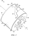
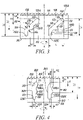
- FIGS. 2 and 3 another embodiment of a hole cutter of the present invention is indicated generally by the reference numeral 100.
- the hole cutter 100 includes a substantially cylindrical blade body 110 that is substantially the same as the blade body 10 described above in connection with FIG. 1 , and therefore like reference numerals preceded by the numeral "1" are used to indicate like elements.
- the primary difference between the blade body 1 10 of FIGS. 2 and 3 and the blade body 10 describe above is in the shape of the fulcrums 120A, 120B and 120C.
- the fulcrums 120A, 120B and 120C are defined by recessed curvilinear or radiused edges or surfaces of the axially-extending slots or apertures 118 that extend angularly in a direction substantially parallel to the cutting edge 114, as opposed to recessed linear edges or surfaces.
- the radiused fulcrums 120A, 120B and 120C generally extend angularly in a direction substantially perpendicular to the axis of rotation X of the cutter 100, and are curved such that each fulcrum surface 120A, 120B and 120C initially extends in a direction away from the cutting edge 114, reaches an apex, and then curves in a direction back towards the cutting edge 114.
- the radiused fulcrums 120A, 120B and 120C create gulletlike edges or surfaces wherein the deepest part of each gullet is closest to the rim 116 or non- working end of the hole cutter 100.
- a tool such as a standard Phillips number 2 screwdriver, can be placed into contact with the curvilinear fulcrums 120A, 120B and 120C, and pivoted about a respective fulcrum 120A, 120B or 120C to lever a slug out of the interior of the blade body 110.
- the fulcrums 120A, 120B and 120C preferably define a radius and/or width W1 sufficient to receive therein a common tool or implement, such as the elongate shaft of a screw driver.
- the width W1 is preferably within the range of about 6.4 mm to about 8.5 mm (1/4 inch to about 1/3 inch.)
- the radiused nature of the fulcrums 120A, 120B anc 120C is advantageous because the fulcrums 120 A, 120B and 120C mimic the shape of common tools, such as the shaft of a screwdriver.
- each fulcrum 120 A, 120B and 120C laterally supports a tool received within the 120 A, 120B or 120C fulcrum to thereby prevent the tool from slipping, sliding or otherwise becoming disengaged from the fulcrum 120A, 120B or 120C when levering a work piece slug.
- the above-described fulcrum shapes and dimensions are only exemplary, and any of numerous other shapes and/or dimensions that are currently known, or that later become known, equally may be employed.
- FIGS. 2 and 3 Another difference between the blade body 1 10 of FIGS. 2 and 3 and the blade body 10 describe above is the angled orientation of the axially-extending slots or apertures 118.
- the axially-extending slots or apertures 118 of the blade 110 are set at a smaller acute angle with respect to the axis X of the blade body 110 as compared to the axially- extending slots or apertures 18 of the blade 10 shown in FIG. 1 .
- the acute angle A is about 47°.
- the hole cutter 100 includes cap 117 welded to the rim 116 of the blade body 110 and forming a part of the non- working end of the hole cutter.
- the cap 117 includes a central hub 128 defining a threaded aperture for threadedly engaging an arbor, a plurality of drive pin apertures 130 substantially equally spaced relative to each other about the central hub 128 for engaging the drive pins of the arbor, and a pair of angularly-extending apertures 132 spaced about 180° apart on opposite sides of the hub 128 relative to each other.
- the angularly-extending apertures 132 are dimensioned and positioned to allow insertion therein of a tool, such as a screw driver, to further facilitate in work piece slug removal.
- a hole cutter not forming part of the present invention is indicated generally by the reference numeral 200.
- the hole cutter 200 includes a substantially cylindrical blade body 210 that is substantially the same as the blade bodies 10 and 110 described above in connection with FIGS. 1 through 3 , and therefore like reference numerals preceded by the numeral "2", or preceded by the numeral "2" instead of the numeral "1 ", are used to indicate like elements.
- the primary difference of the blade body 210 in comparison to the blade bodies described above is that the axially-extending slots or apertures 218 are oriented substantially parallel to the axis of rotation X of the hole cutter 200.
- the blade body 210 forms a relatively small diameter hole cutter 200, and therefore the axially-extending slots 218 cannot define as large a slot area as the larger diameter hole cutters described above, and/or cannot be oriented at acute angles relative to the axis of rotation X of the hole cutter 200.
- the blade body 210 is used to form hole cutters defining blade body diameters within the range of about 22 mm to about 37 mm ( 7/8 inch to about 1-7/16 inches).
- the currently preferred embodiments of smaller diameter hole cutters (e.g., about 21 mm (13/16 inches) diameter or less) define the same slot configuration as illustrated in FIG. 3 , but include only one such slot.
- the first fulcrum 220 A is defined by a curvilinear surface extending laterally from the axially-extending slot 218 substantially parallel to the cutting edge 214, but sloping slightly away from the cutting edge 214 in a direction opposite to the cutting direction of the blade 210.
- the first fulcrum 220A includes only one side edge 221 that is oriented substantially parallel to the axis of rotation X of the hole cutter.
- the third or middle fulcrum 220B is similarly defined by a curvilinear surface extending laterally from the axially-extending slot 218 substantially parallel to the cutting edge 214, but sloping slightly away from the cutting edge 214 in a direction opposite to the cutting direction of the blade 210.
- the third or middle fulcrum 220B includes only one side edge 221 that is oriented substantially parallel to the axis of rotation X of the hole cutter 200, but is curvilinear rather than rectilinear.
- the second fulcrum 220C is defined by the second end 224 of the axially-extending slot 218, and as can be seen, is defined by a curvilinear surface extending substantially parallel to the cutting direction of the blade 210, and two side surfaces 221 extending substantially parallel to the axis of rotation X of the blade 210 and formed by the respective side edges of the second end 224 of the axially-extending slot 218.
- the width W2 of each of the first fulcrums 220A and the third or middle fulcrums 220B is preferably within the range of about 5.1 mm to about 13 mm (2/10 to about 1/2 inch), and more preferable within the range of about 6.4 mm to about 9.5 mm (1/4 to about 3/8 inch).
- the first fulcrums 220A and the third or middle fulcrums 220B need not be as wide as the diameter of a number 2 screwdriver, for example, because part of the screwdriver shaft can be received in the fulcrum 220A, 220B while another portion of the screwdriver shaft can extend into the adjacent portion of the axially-extending slot 218.
- the width W1 of the third fulcrum 220C is preferably at least about 0.27 inch to allow insertion therein of a number 2 screwdriver.
- Another difference of the hole cutter 200 in comparison to the hole cutter 100 described above is the configuration of the first or inlet end 222 of each axially-extending slot 218.
- the side edge 221 of the first fulcrum 220A extends linearly and substantially parallel to the axis of rotation X.
- the first or inlet end 222 of each axially- extending slot 218 is defined by two curvilinear regions.
- a first curvilinear region is contiguous to the first fulcrum side edge 221 and defined by one or more relatively small radii R1
- a second curvilinear region is contiguous to the side edge 223, is defined by one or more larger radii R2 and is located on an opposite side of the axially-extending slot 218 relative to the first fulcrum side edge 221.
- the larger radius R2 imparts a shape to the respective edge of the axially-extending slot 218 that slopes away from the cutting edge 214 in a direction opposite the cutting direction of the blade 210.
- the location of the first fulcrum 220A and the orientation of the respective side edge 221 oriented substantially parallel to the axis of rotation X imparts a relatively wide first end or entrance region 222 to the axially-extending slot 218 to facilitate the flow of chips or dust from the cutting edge 214 into the axially-extending slot 218.
- the width at the inlet end 222 of the axially-extending slot 218 is within the range of about 1-1/4 to about 1-1/2 times the minimum width W1 or width at the outlet end 224 of the axially-extending slot 218, and preferably is at least about 1-1/3 times the width W1.
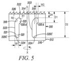
- FIG. 5 another hole cutter not forming part of the present invention is indicated generally by the reference numeral 300.
- the hole cutter 300 includes a substantially cylindrical blade body 310 that is substantially the same as the blade body 210 described above in connection with FIG. 4 , and therefore like reference numerals preceded by the numeral "3" instead of the numeral "2", are used to indicate like elements.
- the primary difference of the blade body 310 in comparison to the blade bodies described in connection with FIG. 4 is that the axially-extending slots or apertures 318 define two fulcrums 320A, 320C instead of three fulcrums.
- the blade body 310 is used to form hole cutters defining blade body diameters within the range of about 22 mm to about 37 mm ( 7/8 inch to about 1-7/16 inches).
- the currently preferred embodiments of smaller diameter hole cutters (e.g., about 21 mm (13/16 inches) diameter or less) define the same slot configuration as illustrated in FIG. 5 , but include only one such slot.
- the second fulcrum 320C is axially spaced from the cutting edge 314 a distance D2 within the range of about 38 mm to about 51 mm ( 1-1/2 inches to about 2 inches).
- the second fulcrum 320C being located in this range is advantageously configured for levering slugs from 2-by wood (e.g., 2 x 4, 2 x 6, 2 x 8, etc.), such as slugs of about 41 mm (1 -5/8 inches) or less.
Landscapes
- Engineering & Computer Science (AREA)
- Mechanical Engineering (AREA)
- Sawing (AREA)
- Drilling Tools (AREA)
- Knives (AREA)
- Details Of Cutting Devices (AREA)
- Harvester Elements (AREA)
Applications Claiming Priority (4)
| Application Number | Priority Date | Filing Date | Title |
|---|---|---|---|
| US12/687,065 US8579554B2 (en) | 2010-01-13 | 2010-01-13 | Hole cutter with axially-elongated aperture defining multiple fulcrums |
| PCT/US2011/021217 WO2011088269A1 (en) | 2010-01-13 | 2011-01-13 | Hole cutter with axially- elongated aperture defining multiple fulcrums |
| US13/006,080 US8579555B2 (en) | 2010-01-13 | 2011-01-13 | Hole cutter with axially-elongated aperture defining multiple fulcrums |
| EP11733410.2A EP2523771B1 (en) | 2010-01-13 | 2011-01-13 | Hole cutter with axially- elongated aperture defining multiple fulcrums |
Related Parent Applications (2)
| Application Number | Title | Priority Date | Filing Date |
|---|---|---|---|
| EP11733410.2A Division-Into EP2523771B1 (en) | 2010-01-13 | 2011-01-13 | Hole cutter with axially- elongated aperture defining multiple fulcrums |
| EP11733410.2A Division EP2523771B1 (en) | 2010-01-13 | 2011-01-13 | Hole cutter with axially- elongated aperture defining multiple fulcrums |
Publications (2)
| Publication Number | Publication Date |
|---|---|
| EP3608046A1 EP3608046A1 (en) | 2020-02-12 |
| EP3608046B1 true EP3608046B1 (en) | 2023-02-15 |
Family
ID=44258651
Family Applications (2)
| Application Number | Title | Priority Date | Filing Date |
|---|---|---|---|
| EP19201282.1A Active EP3608046B1 (en) | 2010-01-13 | 2011-01-13 | Hole cutter with axially-elongated aperture defining multiple fulcrums |
| EP11733410.2A Active EP2523771B1 (en) | 2010-01-13 | 2011-01-13 | Hole cutter with axially- elongated aperture defining multiple fulcrums |
Family Applications After (1)
| Application Number | Title | Priority Date | Filing Date |
|---|---|---|---|
| EP11733410.2A Active EP2523771B1 (en) | 2010-01-13 | 2011-01-13 | Hole cutter with axially- elongated aperture defining multiple fulcrums |
Country Status (8)
Families Citing this family (29)
| Publication number | Priority date | Publication date | Assignee | Title |
|---|---|---|---|---|
| USD659176S1 (en) * | 2010-01-13 | 2012-05-08 | Irwin Industrial Tool Company | Hole saw |
| US8579554B2 (en) * | 2010-01-13 | 2013-11-12 | Irwin Industrial Tool Company | Hole cutter with axially-elongated aperture defining multiple fulcrums |
| US9724766B2 (en) | 2010-01-13 | 2017-08-08 | Irwin Industrial Tool Company | Hole cutter with multiple fulcrums |
| US9782839B2 (en) | 2010-01-13 | 2017-10-10 | Irwin Industrial Tool Company | Hole cutter with chip egress aperture |
| USD690334S1 (en) | 2010-01-13 | 2013-09-24 | Irwin Industrial Tool Company | Hole saw |
| US9808869B2 (en) | 2010-01-13 | 2017-11-07 | Irwin Industrial Tool Company | Hole cutter with chip egress aperture |
| US10137507B2 (en) | 2010-01-13 | 2018-11-27 | Irwin Industrial Tool Company | Hole cutter with multiple fulcrums |
| US9884374B2 (en) | 2015-09-03 | 2018-02-06 | Irwin Industrial Tool Company | Hole cutter with multiple fulcrums |
| MX2014014206A (es) | 2012-05-22 | 2015-06-04 | Owens Corning Intellectual Cap | Producto de espuma laminada y metodos para preparar productos de espuma laminada. |
| US9579732B2 (en) * | 2012-07-18 | 2017-02-28 | Milwaukee Electric Tool Corporation | Hole saw |
| DE102013204421B4 (de) * | 2013-03-14 | 2019-07-11 | Robert Bosch Gmbh | Zylindrischer Bohrkörper für eine Lochsäge |
| USD706845S1 (en) * | 2013-03-14 | 2014-06-10 | Robert Bosch Gmbh | Hole saw |
| USD748701S1 (en) * | 2013-11-27 | 2016-02-02 | Nir Velozny | Inner ring of a construction drilling cup |
| USD748700S1 (en) * | 2013-11-27 | 2016-02-02 | Nir Velozny | Construction drilling cup |
| USD748170S1 (en) * | 2013-11-27 | 2016-01-26 | Nir Velozny | Connector for construction drilling cup |
| USD748702S1 (en) * | 2013-11-27 | 2016-02-02 | Nir Velozny | Accessory for inner ring of drilling cup and for housing of electrical appliances |
| US9597736B2 (en) | 2013-12-19 | 2017-03-21 | Milwaukee Electric Tool Corporation | Adjustable diameter hole cutter |
| US20170157681A1 (en) | 2015-12-08 | 2017-06-08 | Milwaukee Electric Tool Corporation | Hole Saw with Open End Cap Geometry |
| US10384273B2 (en) | 2016-08-24 | 2019-08-20 | The M.K. Morse Company | Hole saw |
| US10940546B2 (en) | 2016-04-19 | 2021-03-09 | The M.K. Morse Company | Ground set hole saw |
| EP3305448B1 (en) | 2016-09-23 | 2020-11-04 | Milwaukee Electric Tool Corporation | Hole saw arbor assembly |
| EP3354385B1 (en) * | 2017-01-06 | 2020-05-27 | Milwaukee Electric Tool Corporation | Hole saw |
| USD973733S1 (en) | 2017-08-15 | 2022-12-27 | Milwaukee Electric Tool Corporation | Hole saw |
| USD845362S1 (en) | 2017-12-04 | 2019-04-09 | Black & Decker Inc. | Holesaw |
| CN216028284U (zh) | 2018-07-10 | 2022-03-15 | 米沃奇电动工具公司 | 孔锯 |
| USD958854S1 (en) | 2018-07-10 | 2022-07-26 | Milwaukee Electric Tool Corporation | Hole saw |
| AU2020295404B2 (en) | 2019-06-20 | 2025-05-29 | Milwaukee Electric Tool Corporation | Hole saw with circular sidewall openings |
| USD958855S1 (en) | 2019-12-09 | 2022-07-26 | Milwaukee Electric Tool Corporation | Hole saw |
| CN113319905B (zh) * | 2021-06-11 | 2022-05-17 | 河北亚奥纺织有限公司 | 一种纺织用粗纺呢绒类圆形地毯切边装置 |
Citations (5)
| Publication number | Priority date | Publication date | Assignee | Title |
|---|---|---|---|---|
| WO1988004588A1 (en) * | 1986-12-18 | 1988-06-30 | Itokazu, Kowa | Hole saw |
| US5451128A (en) * | 1994-01-29 | 1995-09-19 | T. D. Williamson, S.A. | Cutter tool having removable teeth |
| US20060037147A1 (en) * | 2004-08-23 | 2006-02-23 | Henry Redford | Combined nut recess cleaner and nut driver tool |
| USD588175S1 (en) * | 2007-04-30 | 2009-03-10 | Disston Company | Gullet bi-metal hole saw |
| US20190091771A1 (en) * | 2017-09-22 | 2019-03-28 | Kennametal Inc. | Cutting tool and method for manufacturing a cutting tool |
Family Cites Families (39)
| Publication number | Priority date | Publication date | Assignee | Title |
|---|---|---|---|---|
| US2319528A (en) * | 1942-07-23 | 1943-05-18 | Cleveland Quarries Company | Apparatus for drilling holes in stone |
| US2473077A (en) * | 1946-07-06 | 1949-06-14 | Jr Robert M Starbuck | Treapnning tool |
| US2779361A (en) * | 1954-03-17 | 1957-01-29 | Miller Mfg Corp | Sawing tool for cutting circular holes |
| BE788401A (fr) * | 1971-12-29 | 1973-03-05 | Hougen Everett D | Outil rotatif a decouper |
| USD282369S (en) * | 1983-02-07 | 1986-01-28 | Omark Industries | Hole saw |
| JPS59131806U (ja) * | 1983-02-23 | 1984-09-04 | 三菱マテリアル株式会社 | ダイヤモンドコアドリル |
| US4760643A (en) * | 1983-12-30 | 1988-08-02 | Juma Mahmud A M | Hole saw |
| US4652185A (en) * | 1985-04-22 | 1987-03-24 | Malrick David A | Hole saws |
| US5061126A (en) * | 1990-05-04 | 1991-10-29 | Rule Industries | Hole saw and mandrel assembly |
| JPH0616012U (ja) * | 1992-07-28 | 1994-03-01 | ショーボンド建設株式会社 | ダイヤモンドコアビット |
| US5205685A (en) * | 1992-10-05 | 1993-04-27 | Herbert Henry R | Hole saw |
| JPH07124809A (ja) * | 1993-11-01 | 1995-05-16 | Yunika Kk | 切削屑排出孔を備えたコアドリル |
| JPH0966411A (ja) * | 1995-08-31 | 1997-03-11 | Shinto Kogyo Kk | ホールソー |
| US5651646A (en) * | 1995-10-02 | 1997-07-29 | Banke; Michael P. | Hole saw with wood removal feature |
| US5803677A (en) * | 1996-08-09 | 1998-09-08 | Credo Tool Company | Hole saw |
| US5661646A (en) * | 1996-09-25 | 1997-08-26 | The Babcock & Wilcox Company | Multi-phase DC-DC chopper with different number of phases |
| US6820519B2 (en) * | 1998-01-28 | 2004-11-23 | Jacques Lucien Lefebvre | Cork extractor |
| GB2353744A (en) | 1999-09-02 | 2001-03-07 | Marcrist Holdings Ltd | Core cutting tool |
| SE515647C2 (sv) * | 2000-01-11 | 2001-09-17 | Kapman Ab | Eggskydd för hålsåg |
| KR100440871B1 (ko) * | 2001-02-19 | 2004-07-19 | 이화다이아몬드공업 주식회사 | 코어 드릴 |
| US6786684B1 (en) * | 2001-08-15 | 2004-09-07 | Robert J. Ecker | Tubular hole cutter |
| DE10162636A1 (de) * | 2001-12-20 | 2003-07-03 | Hilti Ag | Ultraschallkernbohrkrone |
| USD478919S1 (en) * | 2002-08-02 | 2003-08-26 | South Deerfield Industries, Inc. | Hole saw |
| USD478106S1 (en) * | 2002-08-02 | 2003-08-05 | South Deerfield Industries, Inc. | Hole saw |
| USD478339S1 (en) * | 2002-08-02 | 2003-08-12 | South Deerfield Industries, Inc. | Hole saw |
| USD478105S1 (en) * | 2002-08-02 | 2003-08-05 | South Deerfield Industries, Inc. | Hole saw |
| USD516594S1 (en) * | 2004-04-30 | 2006-03-07 | Kennametal Inc. | Hole saw |
| US7824137B2 (en) * | 2006-05-17 | 2010-11-02 | Maxtech Consumer Products Limited | Universal quick connect system for a hole saw |
| JP4448984B2 (ja) * | 2006-11-01 | 2010-04-14 | 広島県 | 畜産飼料用ドリル式コアサンプラー |
| US9421694B2 (en) * | 2006-11-28 | 2016-08-23 | Kym John Keightley | Hole saw assembly including drive shafts supported by a rotatable annulus |
| CA2618501A1 (en) * | 2007-01-25 | 2008-07-25 | Greenlee Textron Inc. | Hole saw with depth stop |
| US8052356B2 (en) * | 2007-08-01 | 2011-11-08 | Team Fair Holdings Limited | Hole saw system with improved slug removability |
| DE102008036941A1 (de) * | 2008-08-08 | 2010-02-11 | BOA (UK) Limited, Biggin Hill Westerham | Lochsäge |
| US9782839B2 (en) * | 2010-01-13 | 2017-10-10 | Irwin Industrial Tool Company | Hole cutter with chip egress aperture |
| US9808869B2 (en) * | 2010-01-13 | 2017-11-07 | Irwin Industrial Tool Company | Hole cutter with chip egress aperture |
| US9434033B2 (en) * | 2010-01-13 | 2016-09-06 | Irwin Industrial Tool Company | Hole cutter with extruded cap |
| US8573907B2 (en) * | 2010-01-13 | 2013-11-05 | Irwin Industrial Tool Company | Hole cutter with minimum tooth pitch to blade body thickness ratio |
| US9586270B2 (en) * | 2010-01-13 | 2017-03-07 | Irwin Industrial Tool Company | Coated hole cutter |
| US20120183366A1 (en) * | 2011-01-19 | 2012-07-19 | Bruce Winter Stenman | Combination hole saw arbor and adjustable hole cutter shaft |
-
2011
- 2011-01-13 US US13/006,080 patent/US8579555B2/en active Active
- 2011-01-13 JP JP2012549101A patent/JP5816197B2/ja active Active
- 2011-01-13 WO PCT/US2011/021217 patent/WO2011088269A1/en active Application Filing
- 2011-01-13 BR BR112012017115A patent/BR112012017115A2/pt not_active Application Discontinuation
- 2011-01-13 EP EP19201282.1A patent/EP3608046B1/en active Active
- 2011-01-13 EP EP11733410.2A patent/EP2523771B1/en active Active
- 2011-01-13 AU AU2011205763A patent/AU2011205763C1/en not_active Ceased
- 2011-01-13 CA CA2787240A patent/CA2787240C/en active Active
- 2011-01-13 CN CN201180009368.9A patent/CN102781611B/zh active Active
Patent Citations (6)
| Publication number | Priority date | Publication date | Assignee | Title |
|---|---|---|---|---|
| WO1988004588A1 (en) * | 1986-12-18 | 1988-06-30 | Itokazu, Kowa | Hole saw |
| EP0295309B1 (en) * | 1986-12-18 | 1993-05-12 | Yamamoto, Hiroyuki | Hole saw |
| US5451128A (en) * | 1994-01-29 | 1995-09-19 | T. D. Williamson, S.A. | Cutter tool having removable teeth |
| US20060037147A1 (en) * | 2004-08-23 | 2006-02-23 | Henry Redford | Combined nut recess cleaner and nut driver tool |
| USD588175S1 (en) * | 2007-04-30 | 2009-03-10 | Disston Company | Gullet bi-metal hole saw |
| US20190091771A1 (en) * | 2017-09-22 | 2019-03-28 | Kennametal Inc. | Cutting tool and method for manufacturing a cutting tool |
Also Published As
| Publication number | Publication date |
|---|---|
| EP2523771B1 (en) | 2020-02-26 |
| US20110170966A1 (en) | 2011-07-14 |
| WO2011088269A1 (en) | 2011-07-21 |
| CA2787240A1 (en) | 2011-07-21 |
| AU2011205763A1 (en) | 2012-08-30 |
| US8579555B2 (en) | 2013-11-12 |
| CN102781611B (zh) | 2015-01-07 |
| AU2011205763C1 (en) | 2015-08-27 |
| CA2787240C (en) | 2015-02-24 |
| WO2011088269A8 (en) | 2019-11-07 |
| EP2523771A4 (en) | 2014-04-16 |
| EP2523771A1 (en) | 2012-11-21 |
| EP3608046A1 (en) | 2020-02-12 |
| AU2011205763B2 (en) | 2015-01-29 |
| JP5816197B2 (ja) | 2015-11-18 |
| JP2013517149A (ja) | 2013-05-16 |
| BR112012017115A2 (pt) | 2018-07-17 |
| CN102781611A (zh) | 2012-11-14 |
Similar Documents
| Publication | Publication Date | Title |
|---|---|---|
| EP3608046B1 (en) | Hole cutter with axially-elongated aperture defining multiple fulcrums | |
| US8579554B2 (en) | Hole cutter with axially-elongated aperture defining multiple fulcrums | |
| US12036617B2 (en) | Hole cutter with multiple fulcrums | |
| US20230112552A1 (en) | Hole cutter with chip egress aperture | |
| EP2523770B1 (en) | Hole cutter with minimum tooth pitch to blade body thickness ratio | |
| US9884374B2 (en) | Hole cutter with multiple fulcrums | |
| US9808869B2 (en) | Hole cutter with chip egress aperture | |
| EP3725441A1 (en) | Hole saw | |
| US10137507B2 (en) | Hole cutter with multiple fulcrums |
Legal Events
| Date | Code | Title | Description |
|---|---|---|---|
| PUAI | Public reference made under article 153(3) epc to a published international application that has entered the european phase |
Free format text: ORIGINAL CODE: 0009012 |
|
| STAA | Information on the status of an ep patent application or granted ep patent |
Free format text: STATUS: THE APPLICATION HAS BEEN PUBLISHED |
|
| AC | Divisional application: reference to earlier application |
Ref document number: 2523771 Country of ref document: EP Kind code of ref document: P |
|
| AK | Designated contracting states |
Kind code of ref document: A1 Designated state(s): AL AT BE BG CH CY CZ DE DK EE ES FI FR GB GR HR HU IE IS IT LI LT LU LV MC MK MT NL NO PL PT RO RS SE SI SK SM TR |
|
| STAA | Information on the status of an ep patent application or granted ep patent |
Free format text: STATUS: REQUEST FOR EXAMINATION WAS MADE |
|
| 17P | Request for examination filed |
Effective date: 20200716 |
|
| RBV | Designated contracting states (corrected) |
Designated state(s): AL AT BE BG CH CY CZ DE DK EE ES FI FR GB GR HR HU IE IS IT LI LT LU LV MC MK MT NL NO PL PT RO RS SE SI SK SM TR |
|
| GRAP | Despatch of communication of intention to grant a patent |
Free format text: ORIGINAL CODE: EPIDOSNIGR1 |
|
| STAA | Information on the status of an ep patent application or granted ep patent |
Free format text: STATUS: GRANT OF PATENT IS INTENDED |
|
| INTG | Intention to grant announced |
Effective date: 20220829 |
|
| GRAS | Grant fee paid |
Free format text: ORIGINAL CODE: EPIDOSNIGR3 |
|
| GRAA | (expected) grant |
Free format text: ORIGINAL CODE: 0009210 |
|
| STAA | Information on the status of an ep patent application or granted ep patent |
Free format text: STATUS: THE PATENT HAS BEEN GRANTED |
|
| AC | Divisional application: reference to earlier application |
Ref document number: 2523771 Country of ref document: EP Kind code of ref document: P |
|
| AK | Designated contracting states |
Kind code of ref document: B1 Designated state(s): AL AT BE BG CH CY CZ DE DK EE ES FI FR GB GR HR HU IE IS IT LI LT LU LV MC MK MT NL NO PL PT RO RS SE SI SK SM TR |
|
| REG | Reference to a national code |
Ref country code: CH Ref legal event code: EP Ref country code: GB Ref legal event code: FG4D |
|
| REG | Reference to a national code |
Ref country code: DE Ref legal event code: R096 Ref document number: 602011073676 Country of ref document: DE |
|
| REG | Reference to a national code |
Ref country code: AT Ref legal event code: REF Ref document number: 1547982 Country of ref document: AT Kind code of ref document: T Effective date: 20230315 Ref country code: IE Ref legal event code: FG4D |
|
| REG | Reference to a national code |
Ref country code: LT Ref legal event code: MG9D |
|
| REG | Reference to a national code |
Ref country code: NL Ref legal event code: MP Effective date: 20230215 |
|
| REG | Reference to a national code |
Ref country code: AT Ref legal event code: MK05 Ref document number: 1547982 Country of ref document: AT Kind code of ref document: T Effective date: 20230215 |
|
| PG25 | Lapsed in a contracting state [announced via postgrant information from national office to epo] |
Ref country code: RS Free format text: LAPSE BECAUSE OF FAILURE TO SUBMIT A TRANSLATION OF THE DESCRIPTION OR TO PAY THE FEE WITHIN THE PRESCRIBED TIME-LIMIT Effective date: 20230215 Ref country code: PT Free format text: LAPSE BECAUSE OF FAILURE TO SUBMIT A TRANSLATION OF THE DESCRIPTION OR TO PAY THE FEE WITHIN THE PRESCRIBED TIME-LIMIT Effective date: 20230615 Ref country code: NO Free format text: LAPSE BECAUSE OF FAILURE TO SUBMIT A TRANSLATION OF THE DESCRIPTION OR TO PAY THE FEE WITHIN THE PRESCRIBED TIME-LIMIT Effective date: 20230515 Ref country code: NL Free format text: LAPSE BECAUSE OF FAILURE TO SUBMIT A TRANSLATION OF THE DESCRIPTION OR TO PAY THE FEE WITHIN THE PRESCRIBED TIME-LIMIT Effective date: 20230215 Ref country code: LV Free format text: LAPSE BECAUSE OF FAILURE TO SUBMIT A TRANSLATION OF THE DESCRIPTION OR TO PAY THE FEE WITHIN THE PRESCRIBED TIME-LIMIT Effective date: 20230215 Ref country code: LT Free format text: LAPSE BECAUSE OF FAILURE TO SUBMIT A TRANSLATION OF THE DESCRIPTION OR TO PAY THE FEE WITHIN THE PRESCRIBED TIME-LIMIT Effective date: 20230215 Ref country code: HR Free format text: LAPSE BECAUSE OF FAILURE TO SUBMIT A TRANSLATION OF THE DESCRIPTION OR TO PAY THE FEE WITHIN THE PRESCRIBED TIME-LIMIT Effective date: 20230215 Ref country code: ES Free format text: LAPSE BECAUSE OF FAILURE TO SUBMIT A TRANSLATION OF THE DESCRIPTION OR TO PAY THE FEE WITHIN THE PRESCRIBED TIME-LIMIT Effective date: 20230215 Ref country code: AT Free format text: LAPSE BECAUSE OF FAILURE TO SUBMIT A TRANSLATION OF THE DESCRIPTION OR TO PAY THE FEE WITHIN THE PRESCRIBED TIME-LIMIT Effective date: 20230215 |
|
| PG25 | Lapsed in a contracting state [announced via postgrant information from national office to epo] |
Ref country code: SE Free format text: LAPSE BECAUSE OF FAILURE TO SUBMIT A TRANSLATION OF THE DESCRIPTION OR TO PAY THE FEE WITHIN THE PRESCRIBED TIME-LIMIT Effective date: 20230215 Ref country code: PL Free format text: LAPSE BECAUSE OF FAILURE TO SUBMIT A TRANSLATION OF THE DESCRIPTION OR TO PAY THE FEE WITHIN THE PRESCRIBED TIME-LIMIT Effective date: 20230215 Ref country code: IS Free format text: LAPSE BECAUSE OF FAILURE TO SUBMIT A TRANSLATION OF THE DESCRIPTION OR TO PAY THE FEE WITHIN THE PRESCRIBED TIME-LIMIT Effective date: 20230615 Ref country code: GR Free format text: LAPSE BECAUSE OF FAILURE TO SUBMIT A TRANSLATION OF THE DESCRIPTION OR TO PAY THE FEE WITHIN THE PRESCRIBED TIME-LIMIT Effective date: 20230516 Ref country code: FI Free format text: LAPSE BECAUSE OF FAILURE TO SUBMIT A TRANSLATION OF THE DESCRIPTION OR TO PAY THE FEE WITHIN THE PRESCRIBED TIME-LIMIT Effective date: 20230215 |
|
| P01 | Opt-out of the competence of the unified patent court (upc) registered |
Effective date: 20230912 |
|
| PG25 | Lapsed in a contracting state [announced via postgrant information from national office to epo] |
Ref country code: SM Free format text: LAPSE BECAUSE OF FAILURE TO SUBMIT A TRANSLATION OF THE DESCRIPTION OR TO PAY THE FEE WITHIN THE PRESCRIBED TIME-LIMIT Effective date: 20230215 Ref country code: RO Free format text: LAPSE BECAUSE OF FAILURE TO SUBMIT A TRANSLATION OF THE DESCRIPTION OR TO PAY THE FEE WITHIN THE PRESCRIBED TIME-LIMIT Effective date: 20230215 Ref country code: EE Free format text: LAPSE BECAUSE OF FAILURE TO SUBMIT A TRANSLATION OF THE DESCRIPTION OR TO PAY THE FEE WITHIN THE PRESCRIBED TIME-LIMIT Effective date: 20230215 Ref country code: DK Free format text: LAPSE BECAUSE OF FAILURE TO SUBMIT A TRANSLATION OF THE DESCRIPTION OR TO PAY THE FEE WITHIN THE PRESCRIBED TIME-LIMIT Effective date: 20230215 Ref country code: CZ Free format text: LAPSE BECAUSE OF FAILURE TO SUBMIT A TRANSLATION OF THE DESCRIPTION OR TO PAY THE FEE WITHIN THE PRESCRIBED TIME-LIMIT Effective date: 20230215 |
|
| REG | Reference to a national code |
Ref country code: DE Ref legal event code: R097 Ref document number: 602011073676 Country of ref document: DE |
|
| PG25 | Lapsed in a contracting state [announced via postgrant information from national office to epo] |
Ref country code: SK Free format text: LAPSE BECAUSE OF FAILURE TO SUBMIT A TRANSLATION OF THE DESCRIPTION OR TO PAY THE FEE WITHIN THE PRESCRIBED TIME-LIMIT Effective date: 20230215 |
|
| PLBE | No opposition filed within time limit |
Free format text: ORIGINAL CODE: 0009261 |
|
| STAA | Information on the status of an ep patent application or granted ep patent |
Free format text: STATUS: NO OPPOSITION FILED WITHIN TIME LIMIT |
|
| 26N | No opposition filed |
Effective date: 20231116 |
|
| PG25 | Lapsed in a contracting state [announced via postgrant information from national office to epo] |
Ref country code: SI Free format text: LAPSE BECAUSE OF FAILURE TO SUBMIT A TRANSLATION OF THE DESCRIPTION OR TO PAY THE FEE WITHIN THE PRESCRIBED TIME-LIMIT Effective date: 20230215 |
|
| PG25 | Lapsed in a contracting state [announced via postgrant information from national office to epo] |
Ref country code: IT Free format text: LAPSE BECAUSE OF FAILURE TO SUBMIT A TRANSLATION OF THE DESCRIPTION OR TO PAY THE FEE WITHIN THE PRESCRIBED TIME-LIMIT Effective date: 20230215 |
|
| PG25 | Lapsed in a contracting state [announced via postgrant information from national office to epo] |
Ref country code: MC Free format text: LAPSE BECAUSE OF FAILURE TO SUBMIT A TRANSLATION OF THE DESCRIPTION OR TO PAY THE FEE WITHIN THE PRESCRIBED TIME-LIMIT Effective date: 20230215 |
|
| PG25 | Lapsed in a contracting state [announced via postgrant information from national office to epo] |
Ref country code: MC Free format text: LAPSE BECAUSE OF FAILURE TO SUBMIT A TRANSLATION OF THE DESCRIPTION OR TO PAY THE FEE WITHIN THE PRESCRIBED TIME-LIMIT Effective date: 20230215 |
|
| REG | Reference to a national code |
Ref country code: CH Ref legal event code: PL |
|
| PG25 | Lapsed in a contracting state [announced via postgrant information from national office to epo] |
Ref country code: LU Free format text: LAPSE BECAUSE OF NON-PAYMENT OF DUE FEES Effective date: 20240113 |
|
| PG25 | Lapsed in a contracting state [announced via postgrant information from national office to epo] |
Ref country code: LU Free format text: LAPSE BECAUSE OF NON-PAYMENT OF DUE FEES Effective date: 20240113 |
|
| PG25 | Lapsed in a contracting state [announced via postgrant information from national office to epo] |
Ref country code: BE Free format text: LAPSE BECAUSE OF NON-PAYMENT OF DUE FEES Effective date: 20240131 |
|
| PG25 | Lapsed in a contracting state [announced via postgrant information from national office to epo] |
Ref country code: FR Free format text: LAPSE BECAUSE OF NON-PAYMENT OF DUE FEES Effective date: 20240131 |
|
| PG25 | Lapsed in a contracting state [announced via postgrant information from national office to epo] |
Ref country code: CH Free format text: LAPSE BECAUSE OF NON-PAYMENT OF DUE FEES Effective date: 20240131 |
|
| PG25 | Lapsed in a contracting state [announced via postgrant information from national office to epo] |
Ref country code: FR Free format text: LAPSE BECAUSE OF NON-PAYMENT OF DUE FEES Effective date: 20240131 Ref country code: CH Free format text: LAPSE BECAUSE OF NON-PAYMENT OF DUE FEES Effective date: 20240131 Ref country code: BE Free format text: LAPSE BECAUSE OF NON-PAYMENT OF DUE FEES Effective date: 20240131 |
|
| REG | Reference to a national code |
Ref country code: BE Ref legal event code: MM Effective date: 20240131 |
|
| PG25 | Lapsed in a contracting state [announced via postgrant information from national office to epo] |
Ref country code: BG Free format text: LAPSE BECAUSE OF FAILURE TO SUBMIT A TRANSLATION OF THE DESCRIPTION OR TO PAY THE FEE WITHIN THE PRESCRIBED TIME-LIMIT Effective date: 20230215 |
|
| PG25 | Lapsed in a contracting state [announced via postgrant information from national office to epo] |
Ref country code: BG Free format text: LAPSE BECAUSE OF FAILURE TO SUBMIT A TRANSLATION OF THE DESCRIPTION OR TO PAY THE FEE WITHIN THE PRESCRIBED TIME-LIMIT Effective date: 20230215 |
|
| PG25 | Lapsed in a contracting state [announced via postgrant information from national office to epo] |
Ref country code: IE Free format text: LAPSE BECAUSE OF NON-PAYMENT OF DUE FEES Effective date: 20240113 |
|
| PG25 | Lapsed in a contracting state [announced via postgrant information from national office to epo] |
Ref country code: IE Free format text: LAPSE BECAUSE OF NON-PAYMENT OF DUE FEES Effective date: 20240113 |
|
| PGFP | Annual fee paid to national office [announced via postgrant information from national office to epo] |
Ref country code: DE Payment date: 20250120 Year of fee payment: 15 |
|
| PGFP | Annual fee paid to national office [announced via postgrant information from national office to epo] |
Ref country code: GB Payment date: 20250123 Year of fee payment: 15 |
|
| PG25 | Lapsed in a contracting state [announced via postgrant information from national office to epo] |
Ref country code: CY Free format text: LAPSE BECAUSE OF FAILURE TO SUBMIT A TRANSLATION OF THE DESCRIPTION OR TO PAY THE FEE WITHIN THE PRESCRIBED TIME-LIMIT; INVALID AB INITIO Effective date: 20110113 |
|
| PG25 | Lapsed in a contracting state [announced via postgrant information from national office to epo] |
Ref country code: HU Free format text: LAPSE BECAUSE OF FAILURE TO SUBMIT A TRANSLATION OF THE DESCRIPTION OR TO PAY THE FEE WITHIN THE PRESCRIBED TIME-LIMIT; INVALID AB INITIO Effective date: 20110113 |