EP3606832B1 - Anlage sowie verfahren zum herstellen von verpackungsgebinden - Google Patents
Anlage sowie verfahren zum herstellen von verpackungsgebinden Download PDFInfo
- Publication number
- EP3606832B1 EP3606832B1 EP18707687.2A EP18707687A EP3606832B1 EP 3606832 B1 EP3606832 B1 EP 3606832B1 EP 18707687 A EP18707687 A EP 18707687A EP 3606832 B1 EP3606832 B1 EP 3606832B1
- Authority
- EP
- European Patent Office
- Prior art keywords
- packaging
- packagings
- function unit
- medium
- cooling
- Prior art date
- Legal status (The legal status is an assumption and is not a legal conclusion. Google has not performed a legal analysis and makes no representation as to the accuracy of the status listed.)
- Active
Links
Images


Classifications
-
- B—PERFORMING OPERATIONS; TRANSPORTING
- B65—CONVEYING; PACKING; STORING; HANDLING THIN OR FILAMENTARY MATERIAL
- B65B—MACHINES, APPARATUS OR DEVICES FOR, OR METHODS OF, PACKAGING ARTICLES OR MATERIALS; UNPACKING
- B65B53/00—Shrinking wrappers, containers, or container covers during or after packaging
- B65B53/02—Shrinking wrappers, containers, or container covers during or after packaging by heat
- B65B53/06—Shrinking wrappers, containers, or container covers during or after packaging by heat supplied by gases, e.g. hot-air jets
- B65B53/063—Tunnels
-
- B—PERFORMING OPERATIONS; TRANSPORTING
- B65—CONVEYING; PACKING; STORING; HANDLING THIN OR FILAMENTARY MATERIAL
- B65B—MACHINES, APPARATUS OR DEVICES FOR, OR METHODS OF, PACKAGING ARTICLES OR MATERIALS; UNPACKING
- B65B63/00—Auxiliary devices, not otherwise provided for, for operating on articles or materials to be packaged
- B65B63/08—Auxiliary devices, not otherwise provided for, for operating on articles or materials to be packaged for heating or cooling articles or materials to facilitate packaging
Definitions
- the present invention relates to a system (see e.g. US 2011/094616 A1 ) for producing packaging units from at least two packs filled with a level of liquid filling material according to the preamble of claim 1.
- the present invention further relates to a method for producing packaging units according to the preamble of claim 13.
- packaging units takes place in such a way that several packs are put together to form a packaging group in which the packs are tightly connected to one another and that the respective pack is then wrapped or enclosed, preferably with a shrink film.
- Known methods usually use a shrink film which, by applying heat in a shrink tunnel, reduces its dimensions in such a way that the film is placed under tension on the packaging of the respective packaging units and fixes them.
- shrink tunnels for shrinking on shrink film With such shrink tunnels for shrinking on shrink film, a stream of hot air or hot gas is applied, for example, to the side of the respective packaging container already wrapped in the shrink film, in order to shrink the shrink film onto the packaging container. Furthermore, the shrink gas flow can also be directed to the underside of the packaging of the packaging unit wrapped with the shrink film in order to seal, i.e. to weld or glue, the overlapping ends of the shrink film there.
- packaging units consisting of several individual packagings forming a packaging group, which are arranged on a common carrier and connected to the carrier to form a stable packaging unit by a shrunk-on shrink film blank.
- the well-known ones Carriers used in packaging units are preferably made of cardboard or cardboard, while the shrink film blanks are formed from a plastic film designed as a shrink film.
- the deformation or deformation of the PET bottle has the consequence that the closure is no longer located concentrically on the central vertical axis of the PET bottle with its center, but is inclined to the side, for example, at an angle.
- deformations can also occur locally in the upper area of the packaging, which do not result in a change in the position of the closure, but which can be seen as a bulge or dent on the packaging.
- the object of the invention is to provide an improved system for producing packaging units from at least two packs filled with a liquid product, which eliminates the disadvantages of the prior art and in particular in which there is no deformation or deformation of the packaging of the packaging unit in the shrink tunnel .
- a system for producing packaging units from at least two packs filled with a liquid filling material is designed in accordance with claim 1.
- a method for producing packaging units is the subject of patent claim 12.
- the essential aspect of the system according to the invention for producing packaging units from at least two packs filled with a liquid filling material is to be seen in the fact that the system is in front of the in the transport direction second functional unit has at least one spray device and / or cooling device for applying a spray medium and / or cooling medium to the packaging at least in its upper region.
- the packaging container with the spray mist applied to the packaging in the upper area by means of the spray device is particularly advantageously moved into the second functional unit, namely the shrink tunnel.
- the packaging and / or the liquid filling material can be acted upon in the upper region by means of the cooling device, in particular locally cooled.
- the water components of the spray mist of the spray device evaporate, which leads to a cooling of the water components of the spray mist itself and its surroundings.
- This cooling is caused by the fact that the "evaporation or evaporation heat" required for evaporation is withdrawn from the water components of the spray mist and its surroundings, so it is therefore an adiabatic cooling.
- the application of heat in the second functional unit due to the temperature difference that occurs leads to condensation, in particular moisture, on the inner and / or outer surface of the packaging, in particular in the upper area. During condensation, thermal energy is released from the condensate to the environment. This heat of condensation can have the same or approximately the same value as the heat of evaporation.
- the area of the packaging that is not filled with liquid filling material can be exposed to the spray medium and / or cooling medium by means of the at least one spray device and / or cooling device.
- the at least one spray device and / or cooling device at least the The spray medium and / or cooling medium can be acted upon by the spray medium and / or cooling medium from an upper mouth region of the respective packaging up to preferably 2 to 5 cm below a respective filling level of a corresponding packaging.
- the packaging can be acted upon with the spray medium and / or cooling medium in front of the first functional unit with the at least one spray device and / or cooling device.
- the packaging in the area of the first functional unit in particular before providing a respective packaging group with the shrink film, can be exposed to the spray medium and / or cooling medium with the at least one spray device and / or cooling device.
- the packaging in the area of the first functional unit in particular after providing a respective packaging group with the shrink film, and / or after the first functional unit and before the second functional unit with the at least one spray device and / or cooling device can be acted upon with the spray medium and / or cooling medium.
- the at least one spray device for generating a spray mist is designed as a spray medium, the packaging being able to be acted upon by the spray mist at least in its upper region.
- the spray mist generated by the at least one spray device is directed in the direction of the respective packaging conveyed along the treatment path in the transport direction on at least one conveyor in such a way that the spray mist can be applied to at least their respective upper area.
- the respective outer packaging of a packaging group formed from several packaging rows along the treatment line in front of the second functional unit can be acted upon in their respective upper area with the spray generated by the at least one spray device.
- the at least one cooling device is designed to generate a cooling medium in the form of a gaseous cooling atmosphere, preferably cold air, wherein the packaging can be exposed to the gaseous cooling atmosphere at least in its upper area.
- a suction device can be sucked off and / or unsaturated air can be guided by means of a blower device.
- At least one of the spray devices is adjustable in height and / or with respect to the exit angle or its inclination to the horizontal in order to optimally apply a fluid to the container area to be cooled. It can also be useful here for the spray device to be aligned in such a way that it can spray under a film or film section that has already been applied. In particular if the spray device is arranged at or after the film wrapping unit and directly from the entrance to a heat source, such as a shrink tunnel.
- packaging is in particular packaging material filled with a product, for example in the form of containers such as cans, bottles, tubes, pouchers made of metal, glass and / or plastic, but also other packaging materials that are used for filling liquid or viscous Understand products.
- packaging is understood to mean PET bottles filled with a liquid filling material.
- 1 generally denotes a system for producing packaging units 3 from at least two packs 2 filled with a liquid filling material.
- the system 1 is designed in particular as a production system for packaging 2 filled with a liquid filling material, for example bottles filled with a drink, in particular PET bottles.
- the treatment section BS of the system 1 shown here serves specifically to assemble the packs 2 filled with the liquid filling material into packaging groups 4, including using a shrink film 5, so that the packaging group 4 each after the shrink film has been shrunk on packaging units 3, each with a predetermined number of packs 2 form.
- the system 1 includes at least one transporter 6, on whose horizontal or essentially horizontal transport plane E the packaging 2 is transported in a transport direction A along the treatment line BS, for example as a four-lane packaging stream, i.e. as four packages transported side by side at right angles to transport direction A. 2, from which the packaging groups 4 are then separated in the manner known to the person skilled in the art, in which the packaging 2 are provided in close contact with one another.
- a transporter 6 on whose horizontal or essentially horizontal transport plane E the packaging 2 is transported in a transport direction A along the treatment line BS, for example as a four-lane packaging stream, i.e. as four packages transported side by side at right angles to transport direction A. 2, from which the packaging groups 4 are then separated in the manner known to the person skilled in the art, in which the packaging 2 are provided in close contact with one another.
- the transport direction A extends in a longitudinal axis L of the at least one transport control 6.
- Q denotes a transverse axis which is preferably perpendicular or substantially perpendicular to the transport direction A and parallel or substantially parallel to the transport plane E.
- the packages 2 have a centrally running central longitudinal axis MA, which is directed perpendicular to the transport plane E of the at least one transport control 6 during the transport of the respective packages 2 along the treatment path BS.
- the respective central longitudinal axes MA of the packagings 2 forming a packaging group 4 are preferably oriented parallel or essentially parallel to one another along the treatment path BS.
- a packaging container 3 produced by means of the system 1 according to the invention preferably has at least two packs 2 standing side by side at right angles to the transport direction A, that is to say along the transverse axis Q.
- a packaging container 3 can be formed from a packaging group 4 of four packaging rows R1 ... R4 arranged along the transverse axis Q of three packages 2 arranged along the transport direction A, i.e. a total of 12 packages 2.
- the packaging containers 3 can be arranged on a only schematically indicated carrier 7, for example rectangular in plan view, in particular in a tray made of cardboard, for example, on which the already separated packaging group 4 in the area in front of a first functional unit F1 along the treatment path BS, for example is postponed.
- the system 1 comprises several functional units, in particular at least the first functional unit F1 and a second functional unit F2, which are connected to one another along the treatment path BS in the transport direction A.
- the first functional unit F1 is designed as a packaging unit at least for applying a shrink film 5 to the packaging 2.
- the first functional unit F1 can also be designed to place or insert the respective packaging groups 4 on the carrier 7 and then to provide the carrier 7 and the packaging group 4 with the shrink film 5.
- the carriers 7 with the packaging groups 4 placed in them or the packaging group 4 of the first functional unit F1 without carrier 7 are fed to the first functional unit F1 and only the shrink film 5 is applied in the first functional unit F1.
- the first functional unit F1 is followed in the transport direction A by the second functional unit F2, which can be connected to one another via at least one transporter 6.
- the second functional unit F2 is designed as a shrink unit for shrinking the shrink film 5 applied in the first functional unit F1 by heating.
- the action of heat in the second functional unit F2 can take place, for example, through hot air and / or heat or infrared radiation, so that the respective shrink film 5 is shrunk onto the respective packaging group 4 and a transportable and storable packaging container 3 is formed.
- the respective outer packaging 2 i.e. those arranged in the first and last packaging row R1 and R4 in relation to the transverse axis Q, due to their spatial proximity to the heat sources provided in the second functional unit F2 WQ exposed to particularly high levels of heat.
- an essential aspect of the present invention provides that the system 1 in the transport direction A in front of the second functional unit F2 has at least one spray device 20 and / or cooling device 30 for applying a spray medium and / or cooling medium to the packaging 2 at least in its upper region.
- the section of the respective packaging 2 is exposed to the spray medium and / or cooling medium by means of the at least one spray device 20 and / or cooling device 30, which is not filled with liquid filling material, i.e. forms the upper, unfilled free space of the respective packaging .
- section of the respective packaging 2 can also be acted upon with the spray medium and / or cooling medium by means of the at least one spray device 20 and / or cooling device 30 as the upper area which extends from the upper opening area MB of the respective packaging 2, in which, for example, is a PET bottle, the bottle opening and the screw cap are located until preferably 2 to 5 cm below the respective filling level FP of liquid filling material.
- the packaging 2 can be acted upon with the spray medium and / or cooling medium with the at least one spray device 20 and / or cooling device 30 along the treatment path BS in the transport direction A in front of the first functional unit F1.
- the packaging 2 can be exposed to the spray medium and / or cooling medium with the at least one spray device 20 and / or cooling device 30 along the treatment path BS in the area of the first functional unit F1, in particular before the respective packaging group 4 is provided with the shrink film 5 will.
- the packaging 2 can be installed along the treatment section BS in the area of the first functional unit F1, in particular after the respective packaging group 4 has been provided with the shrink film 5, or after the first functional unit F1 and before the second functional unit F2 with the at least one spray device 20 and / or cooling device 30, that is to say immediately before transferring the respective packaging group 4 into the second functional unit F2, with the spray medium and / or cooling medium.
- the in the first Functional unit F1 applied shrink film 5 has openings and / or a perforation, specifically preferably at least in the section which is assigned to the upper area of the packaging 2, that is to say covers the upper area of the packaging 2.
- the resulting vapor of the heat of evaporation and / or heat of condensation is sucked off, for example, by means of a suction device and / or new, unsaturated air is supplied at the same time with a blowing device.
- the at least one spray device 20 is particularly advantageously designed to generate a spray mist 21 as the spray medium and is designed to apply the spray mist 21 to the packaging 2 at least in its upper region.
- the spray mist 21 can be formed at least partially from water and / or an emulsion with water.
- the spray mist 21 can be deposited at least in the upper region of the respective packaging 2 in such a way that water and / or emulsion droplets form on the outer surface of the corresponding packaging 2.
- the spray 21 generated by the at least one spray device 20 is directed in the direction of the respective packages 2 transported along the treatment path BS in the transport direction A on the at least one transporter 6, such that at least their respective upper area can be acted upon by the spray 21.
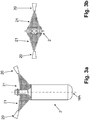
- the at least one spray device 20 can be provided in such a way that at least a first half of the outer circumferential surface of the respective packaging 2 can be acted upon with the spray mist 21 in the respective upper area, i.e. via an outer circumferential surface section which extends over a sector of a circle in relation to the central axis MA of the respective Package 2 extends at least 180 ° ( Figures 2a, 2b ).
- At least two spray devices 20 can be provided in such a way that the outer jacket surface of the respective packaging 2 can be acted upon with the spray mist 21 over its approximately complete outer jacket surface circumference in the upper area ( Figures 3a and 3b ).
- the at least two spray devices 20 can preferably be arranged on opposite sides with respect to the central axis MA of the respective packaging 2, that is to say along an imaginary straight line intersecting the central axis MA.
- the at least one spray device 20 is provided laterally next to the treatment section BS, in particular laterally next to the at least one transporter 6, in front of the second functional unit F2 along the transport direction A, for example by means of a machine frame (not shown) attached to the transporter 6 is.
- the at least one spray device 20 can be provided above the transport plane E laterally next to the treatment section BS in such a way that the spray mist 21 can be applied to at least the respective upper area of the respective packaging 2 conveyed along the treatment section BS in the transport direction A on the at least one conveyor 6 .
- the at least one spray device 20 can also be provided above the respective packages 2 transported along the treatment path BS in the transport direction A on the at least one transporter 6, again in such a way that at least their respective upper area can be acted upon by the spray mist 21.
- the packs 2 which are closest to the lateral heat sources of the second functional unit F2 and which are conveyed along the treatment path BS are acted upon by the spray mist 21 of the spray device 20 in a particularly advantageous manner.
- the system 1 advantageously has a plurality of spray devices 20 at the positions or areas explained above along the treatment path BS.
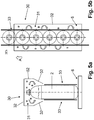
- the at least one cooling device 30 can be designed to generate a cooling medium in the form of a gaseous cooling atmosphere, preferably cold air, wherein the packaging (2) can be exposed to the gaseous cooling atmosphere at least in its upper area.
- the at least one cooling device 30 can advantageously form a cooling zone 31 with the gaseous cooling medium, which extends at least partially along the treatment section BS and is oriented along the longitudinal axis L, which is separated from the atmosphere outside the cooling zone 31 via wall sections 32.
- the wall sections 32 enclose the upper region of the respective packs 2 at least partially along the treatment path BS.
- the packages 2 can be transported through the cooling zone 31 by partition walls 33 between the individual rows of packaging R1 ... R4, in which in the Figures 5a and 5b only one row of packaging is shown as an example, be separated.
- the cooling device 30 can have a separate cooling zone 31 for each row of packaging R1... R4.
- a cooling temperature of the cooling medium can be generated in the cooling zone 31 of the cooling device 30, which, depending on the temperature of the liquid filling material of the packaging 2, is preferably between 20 ° and 50 ° below the temperature of the liquid filling material of the packaging 2 .
- the gaseous cooling medium have a temperature in the form of cold air which is between 20 ° and 50 ° below the temperature of the liquid filling material of the packaging 2.
Landscapes
- Engineering & Computer Science (AREA)
- Mechanical Engineering (AREA)
- Auxiliary Devices For And Details Of Packaging Control (AREA)
Priority Applications (1)
| Application Number | Priority Date | Filing Date | Title |
|---|---|---|---|
| PL18707687T PL3606832T3 (pl) | 2017-04-04 | 2018-02-23 | Układ oraz sposób wytwarzania opakowań zbiorczych |
Applications Claiming Priority (2)
| Application Number | Priority Date | Filing Date | Title |
|---|---|---|---|
| DE102017107176.8A DE102017107176A1 (de) | 2017-04-04 | 2017-04-04 | Anlage sowie Verfahren zum Herstellen von Verpackungsgebinden |
| PCT/EP2018/054493 WO2018184762A1 (de) | 2017-04-04 | 2018-02-23 | Anlage sowie verfahren zum herstellen von verpackungsgebinden |
Publications (2)
| Publication Number | Publication Date |
|---|---|
| EP3606832A1 EP3606832A1 (de) | 2020-02-12 |
| EP3606832B1 true EP3606832B1 (de) | 2021-03-31 |
Family
ID=61386839
Family Applications (1)
| Application Number | Title | Priority Date | Filing Date |
|---|---|---|---|
| EP18707687.2A Active EP3606832B1 (de) | 2017-04-04 | 2018-02-23 | Anlage sowie verfahren zum herstellen von verpackungsgebinden |
Country Status (4)
| Country | Link |
|---|---|
| EP (1) | EP3606832B1 (pl) |
| DE (1) | DE102017107176A1 (pl) |
| PL (1) | PL3606832T3 (pl) |
| WO (1) | WO2018184762A1 (pl) |
Cited By (1)
| Publication number | Priority date | Publication date | Assignee | Title |
|---|---|---|---|---|
| US12351354B2 (en) | 2022-11-09 | 2025-07-08 | Atlantic Corporation Of Wilmington, Inc. | Paper wrapping device and related methods |
Citations (5)
| Publication number | Priority date | Publication date | Assignee | Title |
|---|---|---|---|---|
| DE2046943A1 (de) | 1969-09-26 | 1971-04-22 | Nyborg Plast | Verfahren zur kontinuierlichen, maschi nellen Herstellung von einer Verpackung aus Kunststoffschrumpffolie |
| EP1268280B1 (en) | 2000-04-04 | 2004-05-26 | Decopack S.R.L. | A method of bundling up food containers, in particular bottles |
| DE102013101782A1 (de) | 2013-02-22 | 2014-08-28 | Khs Gmbh | Schrumpftunnelanlage sowie ein zugehöriges Verfahren zum Aufschrumpfen einer Schrumpffolie auf Packformationen |
| WO2015068130A1 (en) | 2013-11-08 | 2015-05-14 | Ocme S.R.L. | Method and apparatus for making a bundle of containers with controlled heat-shrinking, as well as a bundle obtained with such a method |
| EP3070009A1 (de) | 2015-03-17 | 2016-09-21 | Krones Aktiengesellschaft | Vorrichtung und verfahren zur herstellung von folienschrumpfgebinden |
Family Cites Families (6)
| Publication number | Priority date | Publication date | Assignee | Title |
|---|---|---|---|---|
| US3640049A (en) * | 1969-01-29 | 1972-02-08 | Phillips Petroleum Co | Packaging with heat-shrinkable film |
| FR2588828B1 (fr) * | 1985-10-23 | 1988-05-20 | Sleever Int | Procede et appareil pour l'application, par retraction, d'un troncon de gaine thermoretractable autour d'objets a revetir |
| DE102005046304A1 (de) * | 2005-09-27 | 2007-03-29 | Focke & Co.(Gmbh & Co. Kg) | Verfahren und Vorrichtung zur Wärmebehandlung von Packungen |
| CN103625699B (zh) * | 2008-05-20 | 2016-05-11 | 大日本印刷株式会社 | 饮料填充方法和装置 |
| DE102011052101B4 (de) * | 2011-07-25 | 2023-10-05 | Krones Aktiengesellschaft | Schrumpfvorrichtung mit Gebindekühlung |
| DE102013101407A1 (de) * | 2013-02-13 | 2014-08-14 | Khs Gmbh | Verfahren zum Verpacken von flüssigen Produkten unter Druck in Flaschen aus Kunststoff oder dgl. Behälter |
-
2017
- 2017-04-04 DE DE102017107176.8A patent/DE102017107176A1/de active Pending
-
2018
- 2018-02-23 WO PCT/EP2018/054493 patent/WO2018184762A1/de not_active Ceased
- 2018-02-23 PL PL18707687T patent/PL3606832T3/pl unknown
- 2018-02-23 EP EP18707687.2A patent/EP3606832B1/de active Active
Patent Citations (5)
| Publication number | Priority date | Publication date | Assignee | Title |
|---|---|---|---|---|
| DE2046943A1 (de) | 1969-09-26 | 1971-04-22 | Nyborg Plast | Verfahren zur kontinuierlichen, maschi nellen Herstellung von einer Verpackung aus Kunststoffschrumpffolie |
| EP1268280B1 (en) | 2000-04-04 | 2004-05-26 | Decopack S.R.L. | A method of bundling up food containers, in particular bottles |
| DE102013101782A1 (de) | 2013-02-22 | 2014-08-28 | Khs Gmbh | Schrumpftunnelanlage sowie ein zugehöriges Verfahren zum Aufschrumpfen einer Schrumpffolie auf Packformationen |
| WO2015068130A1 (en) | 2013-11-08 | 2015-05-14 | Ocme S.R.L. | Method and apparatus for making a bundle of containers with controlled heat-shrinking, as well as a bundle obtained with such a method |
| EP3070009A1 (de) | 2015-03-17 | 2016-09-21 | Krones Aktiengesellschaft | Vorrichtung und verfahren zur herstellung von folienschrumpfgebinden |
Non-Patent Citations (1)
| Title |
|---|
| KRONES AG: "NitroHotfill bei Pago", YOUTUBE, 29 June 2012 (2012-06-29), XP055876950, Retrieved from the Internet <URL:https://www.youtube.com/watch?v=T0B0ekbdQ68> |
Cited By (1)
| Publication number | Priority date | Publication date | Assignee | Title |
|---|---|---|---|---|
| US12351354B2 (en) | 2022-11-09 | 2025-07-08 | Atlantic Corporation Of Wilmington, Inc. | Paper wrapping device and related methods |
Also Published As
| Publication number | Publication date |
|---|---|
| DE102017107176A1 (de) | 2018-10-04 |
| PL3606832T3 (pl) | 2021-10-18 |
| WO2018184762A1 (de) | 2018-10-11 |
| EP3606832A1 (de) | 2020-02-12 |
Similar Documents
| Publication | Publication Date | Title |
|---|---|---|
| EP3013696B1 (de) | Vorrichtung zum bilden von verpackungseinheiten | |
| DE102012006037B4 (de) | Vorrichtung zur Bildung von Verpackungseinheiten | |
| DE602005002566T2 (de) | Verfahren und anlage zur behälterherstellung | |
| EP2554483A1 (de) | Schrumpftunnel | |
| WO2021043637A1 (de) | Verfahren und verpackungsvorrichtung zur herstellung von verpackungseinheiten | |
| EP3606832B1 (de) | Anlage sowie verfahren zum herstellen von verpackungsgebinden | |
| DE102016123142A1 (de) | Verfahren und Füllmaschine zum Füllen von einseitig offenen Packungen über einen länglichen Düsenschlitz | |
| EP2551207B1 (de) | Schrumpfvorrichtung mit Gebindekühlung | |
| EP3812288A1 (de) | Verfahren und schrumpfvorrichtung zum aufschrumpfen eines thermoplastischen verpackungsmaterials auf artikel | |
| DE102022114548A1 (de) | Schrumpfvorrichtung und ein Verfahren zum Aufschrumpfen thermoplastischen Verpackungsmaterials | |
| DE102017125973B4 (de) | Verfahren zum Bearbeiten und/oder Füllen von Verpackungen | |
| WO2021239318A1 (de) | Verpackungsvorrichtung und verfahren zur herstellung einer verpackungseinheit | |
| DE102013108175B4 (de) | Stapelvorrichtung und Stapelverfahren | |
| DE102013106368B4 (de) | Vorrichtung und Verfahren zur Bildung von Verpackungen | |
| DE102019123830A1 (de) | Verfahren und Verpackungsvorrichtung zur Herstellung von Verpackungseinheiten | |
| WO2018099644A1 (de) | Verfahren und füllmaschine zum füllen von einseitig offenen packungen | |
| DE102022118292A1 (de) | Behälterbehandlungsanlage für Pulpebehälter | |
| DE102011109956B3 (de) | Gebinde | |
| DE102019128873A1 (de) | Verfahren und Schrumpfvorrichtung zum Aufschrumpfen eines thermoplastischen Verpackungsmaterials auf Artikel | |
| DE102021115133A1 (de) | Verfahren zur Ausbildung einer Verpackungseinheit und Vorrichtung zur Herstellung von Verpackungseinheiten | |
| DE102019123835A1 (de) | Verpackungsvorrichtung und Verfahren zur Herstellung von Verpackungseinheiten | |
| DE102023134589A1 (de) | Schrumpfvorrichtung und Verfahren zum Aufschrumpfen eines Schrumpfmaterials auf zumindest teilweise mit dem Schrumpfmaterial umhüllte Artikel | |
| WO2025162802A1 (de) | Schrumpfvorrichtung und verfahren zum aufschrumpfen eines schrumpfmaterials auf zumindest teilweise mit dem schrumpfmaterial umhüllte artikel | |
| DE102022121287A1 (de) | Transport- und Trocknungsmodul, Verpackungsvorrichtung und Verfahren zum Herstellen von Verpackungseinheiten | |
| DE102021132332A1 (de) | Verfahren zur Erstellung von Gebindelagen und/oder Palettenanordnungen, Vorrichtung zur Erstellung von Gebindelagen und/oder Palettenanordnungen; Gebindelage und Palettenanordnung |
Legal Events
| Date | Code | Title | Description |
|---|---|---|---|
| STAA | Information on the status of an ep patent application or granted ep patent |
Free format text: STATUS: UNKNOWN |
|
| STAA | Information on the status of an ep patent application or granted ep patent |
Free format text: STATUS: THE INTERNATIONAL PUBLICATION HAS BEEN MADE |
|
| PUAI | Public reference made under article 153(3) epc to a published international application that has entered the european phase |
Free format text: ORIGINAL CODE: 0009012 |
|
| STAA | Information on the status of an ep patent application or granted ep patent |
Free format text: STATUS: REQUEST FOR EXAMINATION WAS MADE |
|
| 17P | Request for examination filed |
Effective date: 20191104 |
|
| AK | Designated contracting states |
Kind code of ref document: A1 Designated state(s): AL AT BE BG CH CY CZ DE DK EE ES FI FR GB GR HR HU IE IS IT LI LT LU LV MC MK MT NL NO PL PT RO RS SE SI SK SM TR |
|
| AX | Request for extension of the european patent |
Extension state: BA ME |
|
| DAV | Request for validation of the european patent (deleted) | ||
| DAX | Request for extension of the european patent (deleted) | ||
| GRAP | Despatch of communication of intention to grant a patent |
Free format text: ORIGINAL CODE: EPIDOSNIGR1 |
|
| STAA | Information on the status of an ep patent application or granted ep patent |
Free format text: STATUS: GRANT OF PATENT IS INTENDED |
|
| INTG | Intention to grant announced |
Effective date: 20201015 |
|
| GRAS | Grant fee paid |
Free format text: ORIGINAL CODE: EPIDOSNIGR3 |
|
| GRAA | (expected) grant |
Free format text: ORIGINAL CODE: 0009210 |
|
| STAA | Information on the status of an ep patent application or granted ep patent |
Free format text: STATUS: THE PATENT HAS BEEN GRANTED |
|
| AK | Designated contracting states |
Kind code of ref document: B1 Designated state(s): AL AT BE BG CH CY CZ DE DK EE ES FI FR GB GR HR HU IE IS IT LI LT LU LV MC MK MT NL NO PL PT RO RS SE SI SK SM TR |
|
| REG | Reference to a national code |
Ref country code: GB Ref legal event code: FG4D Free format text: NOT ENGLISH Ref country code: CH Ref legal event code: EP |
|
| REG | Reference to a national code |
Ref country code: AT Ref legal event code: REF Ref document number: 1376695 Country of ref document: AT Kind code of ref document: T Effective date: 20210415 |
|
| REG | Reference to a national code |
Ref country code: DE Ref legal event code: R096 Ref document number: 502018004541 Country of ref document: DE |
|
| REG | Reference to a national code |
Ref country code: IE Ref legal event code: FG4D Free format text: LANGUAGE OF EP DOCUMENT: GERMAN |
|
| REG | Reference to a national code |
Ref country code: LT Ref legal event code: MG9D |
|
| PG25 | Lapsed in a contracting state [announced via postgrant information from national office to epo] |
Ref country code: NO Free format text: LAPSE BECAUSE OF FAILURE TO SUBMIT A TRANSLATION OF THE DESCRIPTION OR TO PAY THE FEE WITHIN THE PRESCRIBED TIME-LIMIT Effective date: 20210630 Ref country code: HR Free format text: LAPSE BECAUSE OF FAILURE TO SUBMIT A TRANSLATION OF THE DESCRIPTION OR TO PAY THE FEE WITHIN THE PRESCRIBED TIME-LIMIT Effective date: 20210331 Ref country code: FI Free format text: LAPSE BECAUSE OF FAILURE TO SUBMIT A TRANSLATION OF THE DESCRIPTION OR TO PAY THE FEE WITHIN THE PRESCRIBED TIME-LIMIT Effective date: 20210331 Ref country code: BG Free format text: LAPSE BECAUSE OF FAILURE TO SUBMIT A TRANSLATION OF THE DESCRIPTION OR TO PAY THE FEE WITHIN THE PRESCRIBED TIME-LIMIT Effective date: 20210630 |
|
| PG25 | Lapsed in a contracting state [announced via postgrant information from national office to epo] |
Ref country code: RS Free format text: LAPSE BECAUSE OF FAILURE TO SUBMIT A TRANSLATION OF THE DESCRIPTION OR TO PAY THE FEE WITHIN THE PRESCRIBED TIME-LIMIT Effective date: 20210331 Ref country code: LV Free format text: LAPSE BECAUSE OF FAILURE TO SUBMIT A TRANSLATION OF THE DESCRIPTION OR TO PAY THE FEE WITHIN THE PRESCRIBED TIME-LIMIT Effective date: 20210331 Ref country code: SE Free format text: LAPSE BECAUSE OF FAILURE TO SUBMIT A TRANSLATION OF THE DESCRIPTION OR TO PAY THE FEE WITHIN THE PRESCRIBED TIME-LIMIT Effective date: 20210331 |
|
| REG | Reference to a national code |
Ref country code: NL Ref legal event code: MP Effective date: 20210331 |
|
| PG25 | Lapsed in a contracting state [announced via postgrant information from national office to epo] |
Ref country code: NL Free format text: LAPSE BECAUSE OF FAILURE TO SUBMIT A TRANSLATION OF THE DESCRIPTION OR TO PAY THE FEE WITHIN THE PRESCRIBED TIME-LIMIT Effective date: 20210331 Ref country code: SM Free format text: LAPSE BECAUSE OF FAILURE TO SUBMIT A TRANSLATION OF THE DESCRIPTION OR TO PAY THE FEE WITHIN THE PRESCRIBED TIME-LIMIT Effective date: 20210331 Ref country code: CZ Free format text: LAPSE BECAUSE OF FAILURE TO SUBMIT A TRANSLATION OF THE DESCRIPTION OR TO PAY THE FEE WITHIN THE PRESCRIBED TIME-LIMIT Effective date: 20210331 Ref country code: EE Free format text: LAPSE BECAUSE OF FAILURE TO SUBMIT A TRANSLATION OF THE DESCRIPTION OR TO PAY THE FEE WITHIN THE PRESCRIBED TIME-LIMIT Effective date: 20210331 Ref country code: LT Free format text: LAPSE BECAUSE OF FAILURE TO SUBMIT A TRANSLATION OF THE DESCRIPTION OR TO PAY THE FEE WITHIN THE PRESCRIBED TIME-LIMIT Effective date: 20210331 |
|
| PG25 | Lapsed in a contracting state [announced via postgrant information from national office to epo] |
Ref country code: SK Free format text: LAPSE BECAUSE OF FAILURE TO SUBMIT A TRANSLATION OF THE DESCRIPTION OR TO PAY THE FEE WITHIN THE PRESCRIBED TIME-LIMIT Effective date: 20210331 Ref country code: RO Free format text: LAPSE BECAUSE OF FAILURE TO SUBMIT A TRANSLATION OF THE DESCRIPTION OR TO PAY THE FEE WITHIN THE PRESCRIBED TIME-LIMIT Effective date: 20210331 Ref country code: PT Free format text: LAPSE BECAUSE OF FAILURE TO SUBMIT A TRANSLATION OF THE DESCRIPTION OR TO PAY THE FEE WITHIN THE PRESCRIBED TIME-LIMIT Effective date: 20210802 Ref country code: IS Free format text: LAPSE BECAUSE OF FAILURE TO SUBMIT A TRANSLATION OF THE DESCRIPTION OR TO PAY THE FEE WITHIN THE PRESCRIBED TIME-LIMIT Effective date: 20210731 |
|
| REG | Reference to a national code |
Ref country code: DE Ref legal event code: R026 Ref document number: 502018004541 Country of ref document: DE |
|
| PLBI | Opposition filed |
Free format text: ORIGINAL CODE: 0009260 |
|
| PG25 | Lapsed in a contracting state [announced via postgrant information from national office to epo] |
Ref country code: ES Free format text: LAPSE BECAUSE OF FAILURE TO SUBMIT A TRANSLATION OF THE DESCRIPTION OR TO PAY THE FEE WITHIN THE PRESCRIBED TIME-LIMIT Effective date: 20210331 Ref country code: AL Free format text: LAPSE BECAUSE OF FAILURE TO SUBMIT A TRANSLATION OF THE DESCRIPTION OR TO PAY THE FEE WITHIN THE PRESCRIBED TIME-LIMIT Effective date: 20210331 Ref country code: DK Free format text: LAPSE BECAUSE OF FAILURE TO SUBMIT A TRANSLATION OF THE DESCRIPTION OR TO PAY THE FEE WITHIN THE PRESCRIBED TIME-LIMIT Effective date: 20210331 |
|
| PLAX | Notice of opposition and request to file observation + time limit sent |
Free format text: ORIGINAL CODE: EPIDOSNOBS2 |
|
| 26 | Opposition filed |
Opponent name: KRONES AG Effective date: 20211228 |
|
| PLBB | Reply of patent proprietor to notice(s) of opposition received |
Free format text: ORIGINAL CODE: EPIDOSNOBS3 |
|
| PG25 | Lapsed in a contracting state [announced via postgrant information from national office to epo] |
Ref country code: IS Free format text: LAPSE BECAUSE OF FAILURE TO SUBMIT A TRANSLATION OF THE DESCRIPTION OR TO PAY THE FEE WITHIN THE PRESCRIBED TIME-LIMIT Effective date: 20210731 |
|
| PG25 | Lapsed in a contracting state [announced via postgrant information from national office to epo] |
Ref country code: MC Free format text: LAPSE BECAUSE OF FAILURE TO SUBMIT A TRANSLATION OF THE DESCRIPTION OR TO PAY THE FEE WITHIN THE PRESCRIBED TIME-LIMIT Effective date: 20210331 |
|
| REG | Reference to a national code |
Ref country code: CH Ref legal event code: PL |
|
| REG | Reference to a national code |
Ref country code: BE Ref legal event code: MM Effective date: 20220228 |
|
| PG25 | Lapsed in a contracting state [announced via postgrant information from national office to epo] |
Ref country code: LU Free format text: LAPSE BECAUSE OF NON-PAYMENT OF DUE FEES Effective date: 20220223 |
|
| PG25 | Lapsed in a contracting state [announced via postgrant information from national office to epo] |
Ref country code: LI Free format text: LAPSE BECAUSE OF NON-PAYMENT OF DUE FEES Effective date: 20220228 Ref country code: IE Free format text: LAPSE BECAUSE OF NON-PAYMENT OF DUE FEES Effective date: 20220223 Ref country code: CH Free format text: LAPSE BECAUSE OF NON-PAYMENT OF DUE FEES Effective date: 20220228 |
|
| PG25 | Lapsed in a contracting state [announced via postgrant information from national office to epo] |
Ref country code: BE Free format text: LAPSE BECAUSE OF NON-PAYMENT OF DUE FEES Effective date: 20220228 |
|
| PG25 | Lapsed in a contracting state [announced via postgrant information from national office to epo] |
Ref country code: MK Free format text: LAPSE BECAUSE OF FAILURE TO SUBMIT A TRANSLATION OF THE DESCRIPTION OR TO PAY THE FEE WITHIN THE PRESCRIBED TIME-LIMIT Effective date: 20210331 Ref country code: CY Free format text: LAPSE BECAUSE OF FAILURE TO SUBMIT A TRANSLATION OF THE DESCRIPTION OR TO PAY THE FEE WITHIN THE PRESCRIBED TIME-LIMIT Effective date: 20210331 |
|
| PG25 | Lapsed in a contracting state [announced via postgrant information from national office to epo] |
Ref country code: HU Free format text: LAPSE BECAUSE OF FAILURE TO SUBMIT A TRANSLATION OF THE DESCRIPTION OR TO PAY THE FEE WITHIN THE PRESCRIBED TIME-LIMIT; INVALID AB INITIO Effective date: 20180223 |
|
| PG25 | Lapsed in a contracting state [announced via postgrant information from national office to epo] |
Ref country code: MT Free format text: LAPSE BECAUSE OF FAILURE TO SUBMIT A TRANSLATION OF THE DESCRIPTION OR TO PAY THE FEE WITHIN THE PRESCRIBED TIME-LIMIT Effective date: 20210331 |
|
| PG25 | Lapsed in a contracting state [announced via postgrant information from national office to epo] |
Ref country code: GR Free format text: LAPSE BECAUSE OF NON-PAYMENT OF DUE FEES Effective date: 20210331 |
|
| PG25 | Lapsed in a contracting state [announced via postgrant information from national office to epo] |
Ref country code: GR Free format text: LAPSE BECAUSE OF NON-PAYMENT OF DUE FEES Effective date: 20210331 |
|
| PGFP | Annual fee paid to national office [announced via postgrant information from national office to epo] |
Ref country code: DE Payment date: 20250218 Year of fee payment: 8 |
|
| PGFP | Annual fee paid to national office [announced via postgrant information from national office to epo] |
Ref country code: AT Payment date: 20250219 Year of fee payment: 8 |
|
| PGFP | Annual fee paid to national office [announced via postgrant information from national office to epo] |
Ref country code: FR Payment date: 20250224 Year of fee payment: 8 Ref country code: PL Payment date: 20250214 Year of fee payment: 8 |
|
| PGFP | Annual fee paid to national office [announced via postgrant information from national office to epo] |
Ref country code: IT Payment date: 20250224 Year of fee payment: 8 Ref country code: GB Payment date: 20250220 Year of fee payment: 8 |
|
| PG25 | Lapsed in a contracting state [announced via postgrant information from national office to epo] |
Ref country code: TR Free format text: LAPSE BECAUSE OF FAILURE TO SUBMIT A TRANSLATION OF THE DESCRIPTION OR TO PAY THE FEE WITHIN THE PRESCRIBED TIME-LIMIT Effective date: 20210331 |
|
| RDAF | Communication despatched that patent is revoked |
Free format text: ORIGINAL CODE: EPIDOSNREV1 |
|
| P01 | Opt-out of the competence of the unified patent court (upc) registered |
Free format text: CASE NUMBER: UPC_APP_0014569_3606832/2025 Effective date: 20251125 |