EP3606832B1 - System and method for producing packaging multi-packs - Google Patents
System and method for producing packaging multi-packs Download PDFInfo
- Publication number
- EP3606832B1 EP3606832B1 EP18707687.2A EP18707687A EP3606832B1 EP 3606832 B1 EP3606832 B1 EP 3606832B1 EP 18707687 A EP18707687 A EP 18707687A EP 3606832 B1 EP3606832 B1 EP 3606832B1
- Authority
- EP
- European Patent Office
- Prior art keywords
- packaging
- packagings
- function unit
- medium
- cooling
- Prior art date
- Legal status (The legal status is an assumption and is not a legal conclusion. Google has not performed a legal analysis and makes no representation as to the accuracy of the status listed.)
- Active
Links
- 238000004806 packaging method and process Methods 0.000 title claims description 150
- 238000004519 manufacturing process Methods 0.000 title claims description 7
- 239000007921 spray Substances 0.000 claims description 80
- 238000001816 cooling Methods 0.000 claims description 46
- 229920006300 shrink film Polymers 0.000 claims description 29
- 239000002826 coolant Substances 0.000 claims description 26
- 239000003595 mist Substances 0.000 claims description 24
- 239000007788 liquid Substances 0.000 claims description 22
- 239000000463 material Substances 0.000 claims description 15
- 238000001704 evaporation Methods 0.000 claims description 8
- 230000008020 evaporation Effects 0.000 claims description 8
- 238000009833 condensation Methods 0.000 claims description 6
- 230000005494 condensation Effects 0.000 claims description 6
- 239000012530 fluid Substances 0.000 claims description 3
- 238000010438 heat treatment Methods 0.000 claims description 3
- 238000005507 spraying Methods 0.000 claims 17
- XLYOFNOQVPJJNP-UHFFFAOYSA-N water Substances O XLYOFNOQVPJJNP-UHFFFAOYSA-N 0.000 description 6
- 239000000969 carrier Substances 0.000 description 2
- 239000000839 emulsion Substances 0.000 description 2
- 238000000034 method Methods 0.000 description 2
- 239000005022 packaging material Substances 0.000 description 2
- 238000005192 partition Methods 0.000 description 2
- 239000000047 product Substances 0.000 description 2
- 230000009471 action Effects 0.000 description 1
- 238000007664 blowing Methods 0.000 description 1
- 230000008859 change Effects 0.000 description 1
- 238000011161 development Methods 0.000 description 1
- 230000018109 developmental process Effects 0.000 description 1
- 239000011521 glass Substances 0.000 description 1
- 239000003292 glue Substances 0.000 description 1
- 239000012263 liquid product Substances 0.000 description 1
- 239000002184 metal Substances 0.000 description 1
- 238000012856 packing Methods 0.000 description 1
- 239000004033 plastic Substances 0.000 description 1
- 239000002985 plastic film Substances 0.000 description 1
- 229920006255 plastic film Polymers 0.000 description 1
- 230000008569 process Effects 0.000 description 1
- 230000005855 radiation Effects 0.000 description 1
- 230000007704 transition Effects 0.000 description 1
Images


Classifications
-
- B—PERFORMING OPERATIONS; TRANSPORTING
- B65—CONVEYING; PACKING; STORING; HANDLING THIN OR FILAMENTARY MATERIAL
- B65B—MACHINES, APPARATUS OR DEVICES FOR, OR METHODS OF, PACKAGING ARTICLES OR MATERIALS; UNPACKING
- B65B53/00—Shrinking wrappers, containers, or container covers during or after packaging
- B65B53/02—Shrinking wrappers, containers, or container covers during or after packaging by heat
- B65B53/06—Shrinking wrappers, containers, or container covers during or after packaging by heat supplied by gases, e.g. hot-air jets
- B65B53/063—Tunnels
-
- B—PERFORMING OPERATIONS; TRANSPORTING
- B65—CONVEYING; PACKING; STORING; HANDLING THIN OR FILAMENTARY MATERIAL
- B65B—MACHINES, APPARATUS OR DEVICES FOR, OR METHODS OF, PACKAGING ARTICLES OR MATERIALS; UNPACKING
- B65B63/00—Auxiliary devices, not otherwise provided for, for operating on articles or materials to be packaged
- B65B63/08—Auxiliary devices, not otherwise provided for, for operating on articles or materials to be packaged for heating or cooling articles or materials to facilitate packaging
Definitions
- the present invention relates to a system (see e.g. US 2011/094616 A1 ) for producing packaging units from at least two packs filled with a level of liquid filling material according to the preamble of claim 1.
- the present invention further relates to a method for producing packaging units according to the preamble of claim 13.
- packaging units takes place in such a way that several packs are put together to form a packaging group in which the packs are tightly connected to one another and that the respective pack is then wrapped or enclosed, preferably with a shrink film.
- Known methods usually use a shrink film which, by applying heat in a shrink tunnel, reduces its dimensions in such a way that the film is placed under tension on the packaging of the respective packaging units and fixes them.
- shrink tunnels for shrinking on shrink film With such shrink tunnels for shrinking on shrink film, a stream of hot air or hot gas is applied, for example, to the side of the respective packaging container already wrapped in the shrink film, in order to shrink the shrink film onto the packaging container. Furthermore, the shrink gas flow can also be directed to the underside of the packaging of the packaging unit wrapped with the shrink film in order to seal, i.e. to weld or glue, the overlapping ends of the shrink film there.
- packaging units consisting of several individual packagings forming a packaging group, which are arranged on a common carrier and connected to the carrier to form a stable packaging unit by a shrunk-on shrink film blank.
- the well-known ones Carriers used in packaging units are preferably made of cardboard or cardboard, while the shrink film blanks are formed from a plastic film designed as a shrink film.
- the deformation or deformation of the PET bottle has the consequence that the closure is no longer located concentrically on the central vertical axis of the PET bottle with its center, but is inclined to the side, for example, at an angle.
- deformations can also occur locally in the upper area of the packaging, which do not result in a change in the position of the closure, but which can be seen as a bulge or dent on the packaging.
- the object of the invention is to provide an improved system for producing packaging units from at least two packs filled with a liquid product, which eliminates the disadvantages of the prior art and in particular in which there is no deformation or deformation of the packaging of the packaging unit in the shrink tunnel .
- a system for producing packaging units from at least two packs filled with a liquid filling material is designed in accordance with claim 1.
- a method for producing packaging units is the subject of patent claim 12.
- the essential aspect of the system according to the invention for producing packaging units from at least two packs filled with a liquid filling material is to be seen in the fact that the system is in front of the in the transport direction second functional unit has at least one spray device and / or cooling device for applying a spray medium and / or cooling medium to the packaging at least in its upper region.
- the packaging container with the spray mist applied to the packaging in the upper area by means of the spray device is particularly advantageously moved into the second functional unit, namely the shrink tunnel.
- the packaging and / or the liquid filling material can be acted upon in the upper region by means of the cooling device, in particular locally cooled.
- the water components of the spray mist of the spray device evaporate, which leads to a cooling of the water components of the spray mist itself and its surroundings.
- This cooling is caused by the fact that the "evaporation or evaporation heat" required for evaporation is withdrawn from the water components of the spray mist and its surroundings, so it is therefore an adiabatic cooling.
- the application of heat in the second functional unit due to the temperature difference that occurs leads to condensation, in particular moisture, on the inner and / or outer surface of the packaging, in particular in the upper area. During condensation, thermal energy is released from the condensate to the environment. This heat of condensation can have the same or approximately the same value as the heat of evaporation.
- the area of the packaging that is not filled with liquid filling material can be exposed to the spray medium and / or cooling medium by means of the at least one spray device and / or cooling device.
- the at least one spray device and / or cooling device at least the The spray medium and / or cooling medium can be acted upon by the spray medium and / or cooling medium from an upper mouth region of the respective packaging up to preferably 2 to 5 cm below a respective filling level of a corresponding packaging.
- the packaging can be acted upon with the spray medium and / or cooling medium in front of the first functional unit with the at least one spray device and / or cooling device.
- the packaging in the area of the first functional unit in particular before providing a respective packaging group with the shrink film, can be exposed to the spray medium and / or cooling medium with the at least one spray device and / or cooling device.
- the packaging in the area of the first functional unit in particular after providing a respective packaging group with the shrink film, and / or after the first functional unit and before the second functional unit with the at least one spray device and / or cooling device can be acted upon with the spray medium and / or cooling medium.
- the at least one spray device for generating a spray mist is designed as a spray medium, the packaging being able to be acted upon by the spray mist at least in its upper region.
- the spray mist generated by the at least one spray device is directed in the direction of the respective packaging conveyed along the treatment path in the transport direction on at least one conveyor in such a way that the spray mist can be applied to at least their respective upper area.
- the respective outer packaging of a packaging group formed from several packaging rows along the treatment line in front of the second functional unit can be acted upon in their respective upper area with the spray generated by the at least one spray device.
- the at least one cooling device is designed to generate a cooling medium in the form of a gaseous cooling atmosphere, preferably cold air, wherein the packaging can be exposed to the gaseous cooling atmosphere at least in its upper area.
- a suction device can be sucked off and / or unsaturated air can be guided by means of a blower device.
- At least one of the spray devices is adjustable in height and / or with respect to the exit angle or its inclination to the horizontal in order to optimally apply a fluid to the container area to be cooled. It can also be useful here for the spray device to be aligned in such a way that it can spray under a film or film section that has already been applied. In particular if the spray device is arranged at or after the film wrapping unit and directly from the entrance to a heat source, such as a shrink tunnel.
- packaging is in particular packaging material filled with a product, for example in the form of containers such as cans, bottles, tubes, pouchers made of metal, glass and / or plastic, but also other packaging materials that are used for filling liquid or viscous Understand products.
- packaging is understood to mean PET bottles filled with a liquid filling material.
- 1 generally denotes a system for producing packaging units 3 from at least two packs 2 filled with a liquid filling material.
- the system 1 is designed in particular as a production system for packaging 2 filled with a liquid filling material, for example bottles filled with a drink, in particular PET bottles.
- the treatment section BS of the system 1 shown here serves specifically to assemble the packs 2 filled with the liquid filling material into packaging groups 4, including using a shrink film 5, so that the packaging group 4 each after the shrink film has been shrunk on packaging units 3, each with a predetermined number of packs 2 form.
- the system 1 includes at least one transporter 6, on whose horizontal or essentially horizontal transport plane E the packaging 2 is transported in a transport direction A along the treatment line BS, for example as a four-lane packaging stream, i.e. as four packages transported side by side at right angles to transport direction A. 2, from which the packaging groups 4 are then separated in the manner known to the person skilled in the art, in which the packaging 2 are provided in close contact with one another.
- a transporter 6 on whose horizontal or essentially horizontal transport plane E the packaging 2 is transported in a transport direction A along the treatment line BS, for example as a four-lane packaging stream, i.e. as four packages transported side by side at right angles to transport direction A. 2, from which the packaging groups 4 are then separated in the manner known to the person skilled in the art, in which the packaging 2 are provided in close contact with one another.
- the transport direction A extends in a longitudinal axis L of the at least one transport control 6.
- Q denotes a transverse axis which is preferably perpendicular or substantially perpendicular to the transport direction A and parallel or substantially parallel to the transport plane E.
- the packages 2 have a centrally running central longitudinal axis MA, which is directed perpendicular to the transport plane E of the at least one transport control 6 during the transport of the respective packages 2 along the treatment path BS.
- the respective central longitudinal axes MA of the packagings 2 forming a packaging group 4 are preferably oriented parallel or essentially parallel to one another along the treatment path BS.
- a packaging container 3 produced by means of the system 1 according to the invention preferably has at least two packs 2 standing side by side at right angles to the transport direction A, that is to say along the transverse axis Q.
- a packaging container 3 can be formed from a packaging group 4 of four packaging rows R1 ... R4 arranged along the transverse axis Q of three packages 2 arranged along the transport direction A, i.e. a total of 12 packages 2.
- the packaging containers 3 can be arranged on a only schematically indicated carrier 7, for example rectangular in plan view, in particular in a tray made of cardboard, for example, on which the already separated packaging group 4 in the area in front of a first functional unit F1 along the treatment path BS, for example is postponed.
- the system 1 comprises several functional units, in particular at least the first functional unit F1 and a second functional unit F2, which are connected to one another along the treatment path BS in the transport direction A.
- the first functional unit F1 is designed as a packaging unit at least for applying a shrink film 5 to the packaging 2.
- the first functional unit F1 can also be designed to place or insert the respective packaging groups 4 on the carrier 7 and then to provide the carrier 7 and the packaging group 4 with the shrink film 5.
- the carriers 7 with the packaging groups 4 placed in them or the packaging group 4 of the first functional unit F1 without carrier 7 are fed to the first functional unit F1 and only the shrink film 5 is applied in the first functional unit F1.
- the first functional unit F1 is followed in the transport direction A by the second functional unit F2, which can be connected to one another via at least one transporter 6.
- the second functional unit F2 is designed as a shrink unit for shrinking the shrink film 5 applied in the first functional unit F1 by heating.
- the action of heat in the second functional unit F2 can take place, for example, through hot air and / or heat or infrared radiation, so that the respective shrink film 5 is shrunk onto the respective packaging group 4 and a transportable and storable packaging container 3 is formed.
- the respective outer packaging 2 i.e. those arranged in the first and last packaging row R1 and R4 in relation to the transverse axis Q, due to their spatial proximity to the heat sources provided in the second functional unit F2 WQ exposed to particularly high levels of heat.
- an essential aspect of the present invention provides that the system 1 in the transport direction A in front of the second functional unit F2 has at least one spray device 20 and / or cooling device 30 for applying a spray medium and / or cooling medium to the packaging 2 at least in its upper region.
- the section of the respective packaging 2 is exposed to the spray medium and / or cooling medium by means of the at least one spray device 20 and / or cooling device 30, which is not filled with liquid filling material, i.e. forms the upper, unfilled free space of the respective packaging .
- section of the respective packaging 2 can also be acted upon with the spray medium and / or cooling medium by means of the at least one spray device 20 and / or cooling device 30 as the upper area which extends from the upper opening area MB of the respective packaging 2, in which, for example, is a PET bottle, the bottle opening and the screw cap are located until preferably 2 to 5 cm below the respective filling level FP of liquid filling material.
- the packaging 2 can be acted upon with the spray medium and / or cooling medium with the at least one spray device 20 and / or cooling device 30 along the treatment path BS in the transport direction A in front of the first functional unit F1.
- the packaging 2 can be exposed to the spray medium and / or cooling medium with the at least one spray device 20 and / or cooling device 30 along the treatment path BS in the area of the first functional unit F1, in particular before the respective packaging group 4 is provided with the shrink film 5 will.
- the packaging 2 can be installed along the treatment section BS in the area of the first functional unit F1, in particular after the respective packaging group 4 has been provided with the shrink film 5, or after the first functional unit F1 and before the second functional unit F2 with the at least one spray device 20 and / or cooling device 30, that is to say immediately before transferring the respective packaging group 4 into the second functional unit F2, with the spray medium and / or cooling medium.
- the in the first Functional unit F1 applied shrink film 5 has openings and / or a perforation, specifically preferably at least in the section which is assigned to the upper area of the packaging 2, that is to say covers the upper area of the packaging 2.
- the resulting vapor of the heat of evaporation and / or heat of condensation is sucked off, for example, by means of a suction device and / or new, unsaturated air is supplied at the same time with a blowing device.
- the at least one spray device 20 is particularly advantageously designed to generate a spray mist 21 as the spray medium and is designed to apply the spray mist 21 to the packaging 2 at least in its upper region.
- the spray mist 21 can be formed at least partially from water and / or an emulsion with water.
- the spray mist 21 can be deposited at least in the upper region of the respective packaging 2 in such a way that water and / or emulsion droplets form on the outer surface of the corresponding packaging 2.
- the spray 21 generated by the at least one spray device 20 is directed in the direction of the respective packages 2 transported along the treatment path BS in the transport direction A on the at least one transporter 6, such that at least their respective upper area can be acted upon by the spray 21.
- the at least one spray device 20 can be provided in such a way that at least a first half of the outer circumferential surface of the respective packaging 2 can be acted upon with the spray mist 21 in the respective upper area, i.e. via an outer circumferential surface section which extends over a sector of a circle in relation to the central axis MA of the respective Package 2 extends at least 180 ° ( Figures 2a, 2b ).
- At least two spray devices 20 can be provided in such a way that the outer jacket surface of the respective packaging 2 can be acted upon with the spray mist 21 over its approximately complete outer jacket surface circumference in the upper area ( Figures 3a and 3b ).
- the at least two spray devices 20 can preferably be arranged on opposite sides with respect to the central axis MA of the respective packaging 2, that is to say along an imaginary straight line intersecting the central axis MA.
- the at least one spray device 20 is provided laterally next to the treatment section BS, in particular laterally next to the at least one transporter 6, in front of the second functional unit F2 along the transport direction A, for example by means of a machine frame (not shown) attached to the transporter 6 is.
- the at least one spray device 20 can be provided above the transport plane E laterally next to the treatment section BS in such a way that the spray mist 21 can be applied to at least the respective upper area of the respective packaging 2 conveyed along the treatment section BS in the transport direction A on the at least one conveyor 6 .
- the at least one spray device 20 can also be provided above the respective packages 2 transported along the treatment path BS in the transport direction A on the at least one transporter 6, again in such a way that at least their respective upper area can be acted upon by the spray mist 21.
- the packs 2 which are closest to the lateral heat sources of the second functional unit F2 and which are conveyed along the treatment path BS are acted upon by the spray mist 21 of the spray device 20 in a particularly advantageous manner.
- the system 1 advantageously has a plurality of spray devices 20 at the positions or areas explained above along the treatment path BS.
- the at least one cooling device 30 can be designed to generate a cooling medium in the form of a gaseous cooling atmosphere, preferably cold air, wherein the packaging (2) can be exposed to the gaseous cooling atmosphere at least in its upper area.
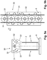
- the at least one cooling device 30 can advantageously form a cooling zone 31 with the gaseous cooling medium, which extends at least partially along the treatment section BS and is oriented along the longitudinal axis L, which is separated from the atmosphere outside the cooling zone 31 via wall sections 32.
- the wall sections 32 enclose the upper region of the respective packs 2 at least partially along the treatment path BS.
- the packages 2 can be transported through the cooling zone 31 by partition walls 33 between the individual rows of packaging R1 ... R4, in which in the Figures 5a and 5b only one row of packaging is shown as an example, be separated.
- the cooling device 30 can have a separate cooling zone 31 for each row of packaging R1... R4.
- a cooling temperature of the cooling medium can be generated in the cooling zone 31 of the cooling device 30, which, depending on the temperature of the liquid filling material of the packaging 2, is preferably between 20 ° and 50 ° below the temperature of the liquid filling material of the packaging 2 .
- the gaseous cooling medium have a temperature in the form of cold air which is between 20 ° and 50 ° below the temperature of the liquid filling material of the packaging 2.
Description
Die vorliegende Erfindung bezieht sich auf eine Anlage (s. z.B.
Grundsätzlich erfolgt die Herstellung von Verpackungsgebinden in der Weise, dass jeweils mehrere Verpackungen zu einer Verpackungsgruppe zusammengestellt werden, in der sich die Verpackungen dicht aneinander anschließen und dass die jeweilige Verpackung dann mit vorzugsweise einer Schrumpffolie umwickelt oder umschlossen wird.In principle, the production of packaging units takes place in such a way that several packs are put together to form a packaging group in which the packs are tightly connected to one another and that the respective pack is then wrapped or enclosed, preferably with a shrink film.
Bekannte Verfahren verwenden in der Regel eine Schrumpffolie, die durch eine Wärmebeaufschlagung in einem Schrumpftunnel ihre Abmessungen derart verringert, dass sich die Folie unter Spannung an die Verpackungen der jeweiligen Verpackungsgebinden anlegt und diese fixiert.Known methods usually use a shrink film which, by applying heat in a shrink tunnel, reduces its dimensions in such a way that the film is placed under tension on the packaging of the respective packaging units and fixes them.
Mit derartigen Schrumpftunnel zum Aufschrumpfen von Schrumpffolie wird ein Heißluft- oder Heißgasstrom beispielweise seitlich auf das jeweilige, mit der Schrumpffolie bereits umhüllte Verpackungsgebinde aufgebracht, um die Schrumpffolie auf das Verpackungsgebinde aufzuschrumpfen. Ferner kann der Schrumpfgasstrom auch auf die Unterseite der mit der Schrumpffolie umhüllten Verpackungen des Verpackungsgebindes gerichtet sein, um die dortigen, sich überlappenden Enden der Schrumpffolie zu versiegeln, d.h. zu verschweißen oder zu verkleben.With such shrink tunnels for shrinking on shrink film, a stream of hot air or hot gas is applied, for example, to the side of the respective packaging container already wrapped in the shrink film, in order to shrink the shrink film onto the packaging container. Furthermore, the shrink gas flow can also be directed to the underside of the packaging of the packaging unit wrapped with the shrink film in order to seal, i.e. to weld or glue, the overlapping ends of the shrink film there.
Auch bekannt sind aus dem Stand der Technik auch Verpackungsgebinde bestehend aus mehreren einzelnen, eine Verpackungsgruppe bildenden, Verpackungen, die auf einem gemeinsamen Träger angeordnet und durch einen aufgeschrumpften Schrumpffolienzuschnitt zusammen mit dem Träger zu einer stabilen Verpackungseinheit verbunden sind. Die bei den bekannten Verpackungseinheiten verwendeten Träger bestehen vorzugsweise aus Karton oder Pappe, während die Schrumpffolienzuschnitte von einer als Schrumpffolie ausgebildeten Kunststofffolie gebildet sind.Also known from the prior art are packaging units consisting of several individual packagings forming a packaging group, which are arranged on a common carrier and connected to the carrier to form a stable packaging unit by a shrunk-on shrink film blank. The well-known ones Carriers used in packaging units are preferably made of cardboard or cardboard, while the shrink film blanks are formed from a plastic film designed as a shrink film.
Insbesondere während der Wärmebeaufschlagung im Schrumpftunnel findet dabei eine direkte Wärmeeinwirkung auf die äußere Mantelfläche der Verpackung, beispielweise der PET-Flasche, statt. Diese Wärmeeinwirkung im oberen Bereich der als PET-Flasche ausgebildeten Verpackung, also einer Wärmeeinwirkung im Kopfbereich der PET-Flasche, kann am Übergang vom Flüssigkeitspegel zum darüber liegenden, unbefüllten Freiraum zu einer möglichen Verformung der Verpackung in diesem Bereich führen. Weiterhin verstärkt wird dieser Effekt bei Verpackungen mit niedrigerem relativen Flüssigkeitspegel, also einem Flüssigkeitspegel, der sich mehrere Zentimeter unterhalb des Verschlusses einer PET-Flasche befindet. Die Verformung bzw. Deformation der PET-Flasche hat zur Folge, dass sich der Verschluss nicht mehr konzentrisch auf der Mittelhochachse der PET-Flasche mit seinem Mittelpunkt befindet, sondern beispielsweise unter einem Winkel zur Seite geneigt ist. Es können aber auch lokal in dem oberen Bereich der Verpackung Verformungen auftreten, die keine Lageänderung des Verschlusses zur Folge haben, sich aber als Beule oder Delle an der Verpackung abzeichnen.In particular, during the application of heat in the shrink tunnel, there is a direct effect of heat on the outer surface of the packaging, for example the PET bottle. This heat effect in the upper area of the packaging designed as a PET bottle, i.e. a heat effect in the head area of the PET bottle, can lead to a possible deformation of the packaging in this area at the transition from the liquid level to the unfilled space above. This effect is further intensified in the case of packaging with a lower relative liquid level, i.e. a liquid level that is several centimeters below the closure of a PET bottle. The deformation or deformation of the PET bottle has the consequence that the closure is no longer located concentrically on the central vertical axis of the PET bottle with its center, but is inclined to the side, for example, at an angle. However, deformations can also occur locally in the upper area of the packaging, which do not result in a change in the position of the closure, but which can be seen as a bulge or dent on the packaging.
Aufgabe der Erfindung ist es, eine verbesserte Anlage zum Herstellen von Verpackungsgebinden aus wenigstens zwei mit einem flüssigen Füllgut gefüllten Verpackungen aufzuzeigen, die die Nachteile des Standes der Technik beseitig und bei der es insbesondere zu keiner Deformation oder Verformung der Verpackungen des Verpackungsgebindes in dem Schrumpftunnel kommt. Zur Lösung dieser Aufgabe ist eine Anlage zum Herstellen von Verpackungsgebinden aus wenigstens zwei mit einem flüssigen Füllgut gefüllten Verpackungen entsprechend dem Patentanspruch 1 ausgebildet. Ein Verfahren zum Herstellen von Verpackungsgebinden ist Gegenstand des Patentanspruchs 12.The object of the invention is to provide an improved system for producing packaging units from at least two packs filled with a liquid product, which eliminates the disadvantages of the prior art and in particular in which there is no deformation or deformation of the packaging of the packaging unit in the shrink tunnel . To achieve this object, a system for producing packaging units from at least two packs filled with a liquid filling material is designed in accordance with claim 1. A method for producing packaging units is the subject of patent claim 12.
Der wesentliche Aspekt der erfindungsgemäßen Anlage zum Herstellen von Verpackungsgebinden aus wenigstens zwei mit einem flüssigen Füllgut gefüllten Verpackungen ist dabei darin zu sehen, dass die Anlage in Transportrichtung vor der zweiten Funktionseinheit zumindest eine Sprühvorrichtung und/oder Kühlvorrichtung zum Beaufschlagen der Verpackungen mit einem Sprühmedium und/oder Kühlmedium zumindest in ihrem oberen Bereich aufweist.The essential aspect of the system according to the invention for producing packaging units from at least two packs filled with a liquid filling material is to be seen in the fact that the system is in front of the in the transport direction second functional unit has at least one spray device and / or cooling device for applying a spray medium and / or cooling medium to the packaging at least in its upper region.
Besonders vorteilhaft wird damit das Verpackungsgebinde mit dem mittels der Sprühvorrichtung auf die Verpackungen im oberen Bereich beaufschlagten Sprühnebel in die zweite Funktionseinheit, nämlich dem Schrumpftunnel, eingefahren. Alternativ oder zusätzlich können die Verpackungen und/oder das flüssige Füllgut im oberen Bereich mittels der Kühlvorrichtung beaufschlagt, insbesondere lokal abgekühlt, werden.In this way, the packaging container with the spray mist applied to the packaging in the upper area by means of the spray device is particularly advantageously moved into the second functional unit, namely the shrink tunnel. Alternatively or additionally, the packaging and / or the liquid filling material can be acted upon in the upper region by means of the cooling device, in particular locally cooled.
Damit kommt es auf Grund der Wärmebeaufschlagung zu einem Verdunsten der Wasseranteile des Sprühnebels der Sprühvorrichtung, was zu einem Abkühlen der Wasseranteile des Sprühnebels selbst und ihrer Umgebung führt. Diese Abkühlung wird dadurch verursacht, dass den Wasseranteilen des Sprühnebels und ihrer Umgebung die zum Verdunsten erforderliche "Verdunstungs- bzw. Verdampfungswärme" entzogen wird, es sich mithin also um eine adiabatische Kühlung handelt. Im Falle der Kühlung im oberen Bereich der Verpackung mittels der Kühlvorrichtung kommt es durch die Wärmebeaufschlagung in der zweiten Funktionseinheit auf Grund der auftretenden Temperaturdifferenz zu einer Kondensation, insbesondere einem Feuchtigkeitsniederschlag, an der inneren und/der äußeren Mantelfläche der Verpackung insbesondere im oberen Bereich. Bei der Kondensation wird Wärmeenergie vom Kondensat an die Umgebung abgegeben. Diese Kondensationswärme kann den gleichen oder näherungsweise gleichen Wert wie die Verdampfungswärme aufweisen.As a result of the application of heat, the water components of the spray mist of the spray device evaporate, which leads to a cooling of the water components of the spray mist itself and its surroundings. This cooling is caused by the fact that the "evaporation or evaporation heat" required for evaporation is withdrawn from the water components of the spray mist and its surroundings, so it is therefore an adiabatic cooling. In the case of cooling in the upper area of the packaging by means of the cooling device, the application of heat in the second functional unit due to the temperature difference that occurs leads to condensation, in particular moisture, on the inner and / or outer surface of the packaging, in particular in the upper area. During condensation, thermal energy is released from the condensate to the environment. This heat of condensation can have the same or approximately the same value as the heat of evaporation.
Gemäß einer Ausführungsvariante kann vorgesehen sein, dass mittels der zumindest einen Sprühvorrichtung und/oder Kühlvorrichtung der nicht mit flüssigem Füllgut gefüllte Bereich der Verpackungen mit dem Sprühmedium und/oder Kühlmedium beaufschlagbar ist.According to one embodiment variant, it can be provided that the area of the packaging that is not filled with liquid filling material can be exposed to the spray medium and / or cooling medium by means of the at least one spray device and / or cooling device.
Gemäß einer weiteren Ausführungsvariante kann vorgesehen sein, dass mittels der zumindest einen Sprühvorrichtung und/oder Kühlvorrichtung zumindest der sich von einem oberen Mündungsbereich der jeweiligen Verpackung bis vorzugsweise 2 bis 5 cm unterhalb eines jeweiligen Füllpegels einer entsprechenden Verpackung mit dem Sprühmedium und/oder Kühlmedium beaufschlagbar ist.According to a further embodiment variant, it can be provided that by means of the at least one spray device and / or cooling device, at least the The spray medium and / or cooling medium can be acted upon by the spray medium and / or cooling medium from an upper mouth region of the respective packaging up to preferably 2 to 5 cm below a respective filling level of a corresponding packaging.
Gemäß einer nochmals weiteren Ausführungsvariante kann vorgesehen sein, dass die Verpackungen vor der ersten Funktionseinheit mit der wenigstens einen Sprühvorrichtung und/oder Kühlvorrichtung mit dem Sprühmedium und/oder Kühlmedium beaufschlagbar sind.According to yet another embodiment variant, it can be provided that the packaging can be acted upon with the spray medium and / or cooling medium in front of the first functional unit with the at least one spray device and / or cooling device.
Gemäß einer nochmals weiteren Ausführungsvariante kann vorgesehen sein, dass die Verpackungen im Bereich der ersten Funktionseinheit, insbesondere vor dem Versehen einer jeweiligen Verpackungsgruppe mit der Schrumpffolie, mit der wenigstens einen Sprühvorrichtung und/oder Kühlvorrichtung mit dem Sprühmedium und/oder Kühlmedium beaufschlagbar sind.According to yet another embodiment variant, it can be provided that the packaging in the area of the first functional unit, in particular before providing a respective packaging group with the shrink film, can be exposed to the spray medium and / or cooling medium with the at least one spray device and / or cooling device.
Gemäß einer nochmals weiteren Ausführungsvariante kann vorgesehen sein, dass die Verpackungen im Bereich der ersten Funktionseinheit, insbesondere nach dem Versehen einer jeweiligen Verpackungsgruppe mit der Schrumpffolie, und/oder nach der ersten Funktionseinheit und vor der zweiten Funktionseinheit mit der wenigstens einen Sprühvorrichtung und/oder Kühlvorrichtung mit dem Sprühmedium und/oder Kühlmedium beaufschlagbar sind.According to yet another embodiment variant, it can be provided that the packaging in the area of the first functional unit, in particular after providing a respective packaging group with the shrink film, and / or after the first functional unit and before the second functional unit with the at least one spray device and / or cooling device can be acted upon with the spray medium and / or cooling medium.
Gemäß einer nochmals weiteren Ausführungsvariante kann vorgesehen sein, dass die wenigstens eine Sprühvorrichtung zur Erzeugung eines Sprühnebels als Sprühmedium ausgebildet ist, wobei die Verpackungen zumindest in ihrem oberen Bereich mit dem Sprühnebel beaufschlagbar sind.According to yet another embodiment variant, it can be provided that the at least one spray device for generating a spray mist is designed as a spray medium, the packaging being able to be acted upon by the spray mist at least in its upper region.
Gemäß einer nochmals weiteren Ausführungsvariante kann vorgesehen sein, dass der durch die wenigstens eine Sprühvorrichtung erzeugte Sprühnebel in Richtung der jeweiligen entlang der Behandlungsstrecke in Transportrichtung auf wenigstens einem Transporteur beförderten Verpackungen derart gerichtet ist, dass wenigstens deren jeweiliger oberer Bereich mit dem Sprühnebel beaufschlagbar ist.According to yet another embodiment variant, it can be provided that the spray mist generated by the at least one spray device is directed in the direction of the respective packaging conveyed along the treatment path in the transport direction on at least one conveyor in such a way that the spray mist can be applied to at least their respective upper area.
Gemäß einer nochmals weiteren Ausführungsvariante kann vorgesehen sein, dass die bezogen auf eine Querachse jeweils äußeren Verpackungen einer aus mehreren Verpackungsreihen gebildeten Verpackungsgruppe entlang der Behandlungsstrecke vor der zweiten Funktionseinheit mit dem durch die wenigstens eine Sprühvorrichtung erzeugten Sprühnebels in ihrem jeweils oberen Bereich beaufschlagbar sind.According to yet another embodiment variant, it can be provided that the respective outer packaging of a packaging group formed from several packaging rows along the treatment line in front of the second functional unit can be acted upon in their respective upper area with the spray generated by the at least one spray device.
Gemäß einer nochmals weiteren Ausführungsvariante kann vorgesehen sein, dass die wenigstens eine Kühlvorrichtung zur Erzeugung eines Kühlmediums in Form von einer gasförmigen Kühlatmosphäre, vorzugsweise kalter Luft, ausgebildet ist, wobei die Verpackungen zumindest in ihrem oberen Bereich mit der gasförmigen Kühlatmosphäre beaufschlagbar sind. Gemäß einer nochmals weiteren Ausführungsvariante kann vorgesehen sein, dass in der zweiten Funktionseinheit mittels einer Saugeinrichtung entstehender Dampf der Verdunstungswärme und/oder Kondensationswärme absaugbar und/oder ungestättigte Luft mittels einer Blaseinrichtung führbar ist.According to yet another embodiment variant, it can be provided that the at least one cooling device is designed to generate a cooling medium in the form of a gaseous cooling atmosphere, preferably cold air, wherein the packaging can be exposed to the gaseous cooling atmosphere at least in its upper area. According to yet another embodiment variant, it can be provided that vapor of the heat of evaporation and / or heat of condensation arising in the second functional unit by means of a suction device can be sucked off and / or unsaturated air can be guided by means of a blower device.
Dabei ist mindestens eine der Sprühvorrichtungen in der Höhenlage und/oder bezüglich des Austrittwinkels oder ihrer Neigung zur Horizontalen verstellbar, um optimal auf den zu kühlenden Behälterbereich ein Fluid zu applizieren. Dabei kann es auch sinnvoll sein, dass die Sprühvorrichtung so ausgerichtet ist, dass diese unter eine bereits aufgelegte oder Folie oder Folienabschnitt sprühen kann. Insbesondere wenn die Sprühvorrichtung auf Höhe oder nach der Folieneinschlageinheit und unmittelbar von dem Eingang zu einer Wärmquelle, wie eines Schrumpftunnels, angeordnet ist.At least one of the spray devices is adjustable in height and / or with respect to the exit angle or its inclination to the horizontal in order to optimally apply a fluid to the container area to be cooled. It can also be useful here for the spray device to be aligned in such a way that it can spray under a film or film section that has already been applied. In particular if the spray device is arranged at or after the film wrapping unit and directly from the entrance to a heat source, such as a shrink tunnel.
Unter Verpackungen sind im Sinne der vorliegenden Erfindung insbesondere mit einem Produkt gefüllte Packmittel, beispielsweise in Form von Behältern, wie Dosen, Flaschen, Tuben, Pouchers aus Metall, Glas und/oder Kunststoff, aber auch andere Packmittel, die zum Abfüllen von flüssigen oder viskosen Produkten zu verstehen. Vorzugsweise werden unter Verpackungen mit einem flüssigen Füllgut befüllte PET-Flaschen verstanden.For the purposes of the present invention, packaging is in particular packaging material filled with a product, for example in the form of containers such as cans, bottles, tubes, pouchers made of metal, glass and / or plastic, but also other packaging materials that are used for filling liquid or viscous Understand products. Preferably, packaging is understood to mean PET bottles filled with a liquid filling material.
Der Ausdruck "im Wesentlichen" bzw. "etwa" bzw. "ca." bedeutet im Sinne der Erfindung Abweichungen vom jeweils exakten Wert um +/- 10%, bevorzugt um +/- 5% und/oder Abweichungen in Form von für die Funktion unbedeutenden Änderungen.The expression "essentially" or "approximately" or "approx." In the context of the invention means deviations from the exact value in each case by +/- 10%, preferably by +/- 5% and / or deviations in the form of changes that are insignificant for the function.
Weiterbildungen, Vorteile und Anwendungsmöglichkeiten der Erfindung ergeben sich auch aus der nachfolgenden Beschreibung von Ausführungsbeispielen und aus den Figuren. Dabei sind alle beschriebenen und/oder bildlich dargestellten Merkmale für sich oder in beliebiger Kombination grundsätzlich Gegenstand der Erfindung, unabhängig von ihrer Zusammenfassung in den Ansprüchen oder deren Rückbeziehung. Auch wird der Inhalt der Ansprüche zu einem Bestandteil der Beschreibung gemacht.Developments, advantages and possible applications of the invention also emerge from the following description of exemplary embodiments and from the figures. In this case, all of the features described and / or shown in the figures, individually or in any combination, are fundamentally the subject matter of the invention, regardless of how they are summarized in the claims or their reference. The content of the claims is also made part of the description.
Die Erfindung wird im Folgenden anhand der Figuren an Ausführungsbeispielen näher erläutert. Es zeigen:
- Fig. 1
- in schematischer Funktionsdarstellung eine beispielhafte Ausführungsvariante einer erfindungsgemäßen Anlage zum Herstellen von Verpackungsgebinden mit wenigstens einer Sprühvorrichtung,
- Fig. 2a und 2b
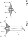
- in schematischer Seitenansicht bzw. Draufsicht eine Ausführungsvariante einer freigestellten Sprühvorrichtung mit exemplarischer Verpackung
- Fig. 3a und 3b
- in schematischer Seitenansicht bzw. Draufsicht eine weitere Ausführungsvariante einer freigestellten Sprühvorrichtung mit exemplarischer Verpackung
- Fig.4
- in schematischer Draufsicht eine Verpackungsgebinde entlang der Behandlungsstrecke in der zweiten Funktionseinheit
- Fig.5a und 5b
- in schematischer Seitenansicht bzw. Draufsicht eine Ausführungsvariante einer freigestellten Kühlvorrichtung mit exemplarischer Verpackung und
- Fig. 6
- in schematischer Funktionsdarstellung eine weitere beispielhafte Ausführungsvarianter einer erfindungsgemäßen Anlage zum Herstellen von Verpackungsgebinden mit wenigstens einer Kühlvorrichtung.
- Fig. 1
- a schematic functional representation of an exemplary embodiment of a system according to the invention for producing packaging units with at least one spray device,
- Figures 2a and 2b
- a schematic side view or top view of an embodiment variant of an exposed spray device with exemplary packaging
- Figures 3a and 3b
- in a schematic side view or plan view, a further embodiment variant of an exposed spray device with exemplary packaging
- Fig. 4
- a schematic plan view of a packaging container along the treatment section in the second functional unit
- Fig. 5a and 5b
- a schematic side view or plan view of an embodiment variant of an exposed cooling device with exemplary packaging and
- Fig. 6
- a schematic functional illustration of a further exemplary embodiment variant of a system according to the invention for producing packaging units with at least one cooling device.
Für gleiche oder gleich wirkende Elemente der Erfindung werden in den Figuren identische Bezugszeichen verwendet. Ferner werden der Übersichtlichkeit halber nur Bezugszeichen in den einzelnen Figuren dargestellt, die für die Beschreibung der jeweiligen Figur erforderlich sind.Identical reference symbols are used in the figures for elements of the invention that are identical or have the same effect. Furthermore, for the sake of clarity, only reference symbols are shown in the individual figures that are necessary for the description of the respective figure.
In den Figuren ist mit 1 allgemein eine Anlage zum Herstellen von Verpackungsgebinden 3 aus wenigstens zwei mit einem flüssigen Füllgut gefüllten Verpackungen 2 bezeichnet. Die Anlage 1 ist dabei insbesondere als Produktionsanlage für mit einem flüssigen Füllgut gefüllte Verpackungen 2, z.B. mit einem Getränk befüllte Flaschen, insbesondere PET-Flaschen, ausgebildet. Die in der
Die Anlage 1 umfasst u.a. wenigstens einen Transporteur 6, auf dessen horizontalen oder im Wesentlichen horizontalen Transportebene E die Verpackungen 2 in einer Transportrichtung A entlang der Behandlungsstrecke BS befördert werden, und zwar beispielsweise als vierspuriger Verpackungsstrom, also als vier quer zur Transportrichtung A nebeneinander beförderten Verpackungen 2, aus dem dann in der dem Fachmann bekannten Weise die Verpackungsgruppen 4 abgetrennt werden, in denen die Verpackungen 2 dicht aneinander anliegend vorgesehen sind.The system 1 includes at least one
Die Transportrichtung A erstreckt sich in einer Längsachse L des wenigstens einen Transporteuers 6. Mit Q ist eine Querachse bezeichnet, die vorzugsweise lotrecht oder im Wesentlichen lotrecht zur Transportrichtung A und parallel oder im Wesentlichen parallel zur Transportebene E orientiert ist. Die Verpackungen 2 weisen dabei eine zentrisch verlaufende Mittellängsachse MA auf, die während des Transports der jeweiligen Verpackungen 2 entlang der Behandlungsstrecke BS lotrecht zur Transportebene E des wenigstens einen Transporteuers 6 gerichtet ist.The transport direction A extends in a longitudinal axis L of the at least one
Die jeweiligen Mittellängsachsen MA der eine Verpackungsgruppe 4 bildenden Verpackungen 2 sind vorzugsweise parallel oder im Wesentlichen parallel zueinander entlang der Behandlungsstrecke BS orientiert. Vorzugsweise weist ein mittels der erfindungsgemäßen Anlage 1 hergestelltes Verpackungsgebinde 3 dabei wenigstens zwei quer zur Transportrichtung A, also entlang der Querachse Q nebeneinander stehende, Verpackungen 2 auf. Wie insbesondere aus der
Die Verpackungsgebinde 3 können dabei auf einem nur schematische angedeuteten, in Draufsicht beispielweise rechteckförmigen Träger 7, insbesondere in einem Tray zum Beispiel aus Karton, angeordnet sein, auf den die bereits jeweils abgetrennte Verpackungsgruppe 4 im Bereich vor einer ersten Funktionseinheit F1 entlang der Behandlungstrecke BS beispielweise aufgeschoben wird.The
Die erfindungsgemäße Anlage 1 umfasst dabei mehrere Funktionseinheiten, insbesondere zumindest die erste Funktionseinheit F1 sowie eine zweite Funktionseinheit F2, die sich entlang der Behandlungsstrecke BS in Transportrichtung A aneinander anschließen.The system 1 according to the invention comprises several functional units, in particular at least the first functional unit F1 and a second functional unit F2, which are connected to one another along the treatment path BS in the transport direction A.
Die erste Funktionseinheit F1 ist dabei als Verpackungseinheit wenigstens zum Aufbringen einer Schrumpffolie 5 auf die Verpackungen 2 ausgebildet. Dabei kann die erste Funktionseinheit F1 auch dazu ausgebildet sein, die jeweiligen Verpackungsgruppen 4 auf den Träger 7 aufzusetzen bzw. einzusetzen und anschließend den Träger 7 und die Verpackungsgruppe 4 mit der Schrumpffolie 5 zu versehen. Grundsätzlich ist dabei auch möglich, dass der ersten Funktionseinheit F1 die Träger 7 bereits mit den in diesen platzierten Verpackungsgruppen 4 oder die Verpackungsgruppe 4 der ersten Funktionseinheit F1 ohne Träger 7 zugeführt werden und in der ersten Funktionseinheit F1 lediglich das Aufbringen der Schrumpffolie 5 erfolgt.The first functional unit F1 is designed as a packaging unit at least for applying a shrink film 5 to the
Dabei folgt auf die erste Funktionseinheit F1 in Transportrichtung A die zweite Funktionseinheit F2, die über den wenigsten einen Transporteur 6 miteinander verbunden sein können. Die zweite Funktionseinheit F2 ist dabei als Schrumpfeinheit zum Schrumpfen der in der ersten Funktionseinheit F1 aufgebrachten Schrumpffolie 5 durch Erhitzen ausgebildet. Die Hitzeeinwirkung in der zweiten Funktionseinheit F2 kann beispielweise durch Heißluft und/oder Wärme- bzw. Infrarotstrahlung erfolgen, so dass die jeweilige Schrumpffolie 5 auf die jeweilige Verpackungsgruppe 4 aufgeschrumpft und ein transport- und lagerfähiges Verpackungsgebinde 3 gebildet ist. Wie beispielweise aus der
Damit es in diesem Herstellungsschritt der Verpackungsgebinden 3 zu keinen Deformationen oder Verformungen der Verpackungen 2 des Verpackungsgebinde 3 in der zweiten Funktionseinheit F2 kommt ist nach einem wesentlichen Aspekt der vorliegenden Erfindung vorgesehen, dass die Anlage 1 in Transportrichtung A vor der zweiten Funktionseinheit F2 zumindest eine Sprühvorrichtung 20 und/oder Kühlvorrichtung 30 zum Beaufschlagen der Verpackungen 2 mit einem Sprühmedium und/oder Kühlmedium zumindest in ihrem oberen Bereich aufweist. Besonders vorteilhaft wird als oberer Bereich der Abschnitt der jeweiligen Verpackung 2 mittels der zumindest einen Sprühvorrichtung 20 und/oder Kühlvorrichtung 30 mit dem Sprühmedium und/oder Kühlmedium beaufschlagt, der nicht mit flüssigem Füllgut gefüllt ist, also den oberen, ungefüllten Freiraum der jeweiligen Verpackung ausbildet.So that there is no deformation or deformation of the
Weiter kann als oberer Bereich auch derjenige Abschnitt der jeweiligen Verpackung 2 mittels der zumindest einen Sprühvorrichtung 20 und/oder Kühlvorrichtung 30 mit dem Sprühmedium und/oder Kühlmedium beaufschlagt werden, der sich von dem oberen Mündungsbereich MB der jeweiligen Verpackung 2, in dem sich beispielweise bei einer PET-Flasche die Flaschenöffnung sowie der Drehverschluss befindet, bis vorzugsweise 2 bis 5cm unterhalb des jeweiligen Füllpegels FP an flüssigen Füllgut erstrecken.Furthermore, that section of the
Ferner kann vorgesehen sein, dass die Verpackungen 2 entlang der Behandlungsstrecke BS in Transportrichtung A vorder ersten Funktionseinheit F1 mit der wenigstens einen Sprühvorrichtung 20 und/oder Kühlvorrichtung 30 mit dem Sprühmedium und/oder Kühlmedium beaufschlagbar sind.Furthermore, it can be provided that the
Alternativ oder zusätzlich können die Verpackungen 2 entlang der Behandlungsstrecke BS im Bereich der ersten Funktionseinheit F1, insbesondere vor dem Versehen der jeweiligen Verpackungsgruppe 4 mit der Schrumpffolie 5, mit der wenigstens einen Sprühvorrichtung 20 und/oder Kühlvorrichtung 30 mit dem Sprühmedium und/oder Kühlmedium beaufschlagt werden.Alternatively or additionally, the
Alternativ oder zusätzlich können die Verpackungen 2 entlang der Behandlungsstrecke BS im Bereich der ersten Funktionseinheit F1, insbesondere nach dem Versehen der jeweiligen Verpackungsgruppe 4 mit der Schrumpffolie 5, oder nach der ersten Funktionseinheit F1 und vor der zweiten Funktionseinheit F2 mit der wenigstens einen Sprühvorrichtung 20 und/oder Kühlvorrichtung 30, also unmittelbar vor zum Überführen der jeweiligen Verpackungsgruppe 4 in die zweite Funktionseinheit F2, mit dem Sprühmedium und/oder Kühlmedium beaufschlagt werden. Insbesondere kann hierbei vorgesehen sein, dass die in der ersten Funktionseinheit F1 aufgebrachte Schrumpffolie 5 Öffnungen und/oder eine Perforation aufweist, und zwar vorzugsweise zumindest in dem Abschnitt, der den oberen Bereich der Verpackungen 2 zugeordnet ist, also den oberen Bereich der Verpackungen 2 abdeckt.Alternatively or additionally, the
Um den Verdunstungsvorgang weitergehend zu begünstigen, kann vorgesehen sein, dass in der zweiten Funktionseinheit F2 der entstehende Dampf der Verdunstungswärme und/oder Kondensationswärme beispielweise mittels einer Saugeinrichtung abgesaugt wird und/oder gleichzeitig mit einer Blaseinrichtung neue, ungestättigte Luft zugeführt wird.In order to further promote the evaporation process, it can be provided that in the second functional unit F2 the resulting vapor of the heat of evaporation and / or heat of condensation is sucked off, for example, by means of a suction device and / or new, unsaturated air is supplied at the same time with a blowing device.
Besonders vorteilhaft ist die wenigstens eine Sprühvorrichtung 20 dazu ausgebildet, als Sprühmedium einen Sprühnebel 21 zu erzeugen und dazu ausgebildet, die Verpackungen 2 zumindest in ihrem oberen Bereich mit dem Sprühnebel 21 zu beaufschlagen. Der Sprühnebel 21 kann dabei zumindest teilweise aus Wasser und/oder einer Emulsion mit Wasser gebildet sein. Insbesondere kann sich der Sprühnebel 21 zumindest im oberen Bereich der jeweiligen Verpackung 2 derart niederschlagen, dass sich an der Außenmantelfläche der entsprechenden Verpackung 2 Wasser- und/oder Emulsionstropfen ausbilden.The at least one
Hierfür ist der durch die wenigstens eine Sprühvorrichtung 20 erzeugte Sprühnebel 21 in Richtung der jeweiligen entlang der Behandlungsstrecke BS in Transportrichtung A auf dem wenigstens einen Transporteuer 6 beförderten Verpackungen 2 gerichtet, derart, dass zumindest deren jeweiliger oberer Bereich mit dem Sprühnebel 21 beaufschlagbar ist.For this purpose, the
Insbesondere kann die zumindest eine Sprühvorrichtung 20 derart vorgesehen sein, dass zumindest eine erste Hälfte der Außenmantelumfangsfläche der jeweiligen Verpackung 2 mit dem Sprühnebel 21 im jeweiligen oberen Bereich beaufschlagbar ist, also über einen Außenmantelumfangsflächenabschnitt, der sich über einen Kreissektor bezogen auf die Mittelache MA der jeweiligen Verpackung 2 von zumindest 180° erstreckt (
Alternativ oder zusätzliche können zumindest zwei Sprühvorrichtungen 20 derart vorgesehen sein, dass die Außenmantelfläche der jeweiligen Verpackung 2 über ihren näherungsweise vollständigen Außenmantelflächenumfang im oberen Bereich mit dem Sprühnebel 21 beaufschlagbar ist (
Beispielsweise kann hierfür vorgesehen sein, dass die zumindest eine Sprühvorrichtung 20 seitlich neben der Behandlungsstrecke BS, insbesondere seitlich neben dem wenigstens einen Transporteuer 6, vor der zweiten Funktionseinheit F2 entlang der Transportrichtung A vorgesehen, beispielweise mittels eines nicht dargestellten Maschinenrahmens an dem Transporteur 6, befestigt ist.For example, it can be provided for this that the at least one
Insbesondere kann die wenigstens eine Sprühvorrichtung 20 oberhalb der Transportebene E seitlich neben der Behandlungsstrecke BS derart vorgesehen sein, dass zumindest der jeweils obere Bereich der jeweiligen entlang der Behandlungsstrecke BS in Transportrichtung A auf dem wenigstens einen Transporteuer 6 beförderten Verpackungen 2 mit dem Sprühnebel 21 beaufschlagbar sind.In particular, the at least one
Alternativ oder zusätzlich kann die zumindest einen Sprühvorrichtung 20 auch oberhalb der jeweiligen entlang der Behandlungsstrecke BS in Transportrichtung A auf dem wenigstens einen Transporteuer 6 beförderten Verpackungen 2 vorgesehen sein, und zwar wiederum derart, dass zumindest deren jeweiliger oberer Bereich mit dem Sprühnebel 21 beaufschlagbar ist.As an alternative or in addition, the at least one
Besonders vorteilhaft werden dabei die jeweils äußeren Verpackungen 2, also die bezogen auf die Querachse Q in der ersten Verpackungsreihe R1 und letzten Verpackungsreihe, beispielsweise der vierten Verpackungsreihe R4, angeordneten Verpackungen 2 einer jeweiligen Verpackungsgruppe 4 entlang der Behandlungsstrecke BS vor der zweiten Funktionseinheit F2 mit dem durch die wenigstens eine Sprühvorrichtung 20 erzeugten Sprühnebel 21 in ihrem jeweiligen oberen Bereich beaufschlagt. Besonders vorteilhaft sind damit zumindest die den seitlichen Wärmequellen der zweiten Funktionseinheit F2 am nähersten liegenden und entlang der Behandlungsstrecke BS beförderten Verpackungen 2 mit dem Sprühnebel 21 der Sprühvorrichtung 20 beaufschlagt.Particularly advantageous are the respective
Vorteilhafterweise weist die Anlage 1 dabei mehrere Sprühvorrichtungen 20 an den jeweils oben stehenden erläuterten Positionen bzw. Bereichen entlang der Behandlungstrecke BS auf.The system 1 advantageously has a plurality of
Wie insbesondere aus den
Insbesondere umschließen die Wandabschnitte 32 den oberen Bereich der jeweiligen Verpackungen 2 zumindest teilweise entlang der Behandlungsstrecke BS. Dabei können die Verpackungen 2 während des Transports durch die Kühlzone 31 durch Trennwände 33 zwischen den einzelnen Verpackungsreihen R1...R4, in denen in den
Mittels eines nicht nähergehend dargestellten Kühlaggregates kann in der Kühlzone 31 der Kühlvorrichtung 30 eine Kühltemperatur des Kühlmediums erzeugt werden, die abhängig von der Temperatur des flüssigen Füllgutes der Verpackungen 2, vorzugsweise zwischen 20° und 50° unterhalb der Temperatur des flüssigen Füllgutes der Verpackungen 2 liegt. Insbesondere kann das gasförmige Kühlmedium in Form von kalter Luft eine Temperatur aufweisen, die zwischen 20° und 50° unterhalb der Temperatur des flüssigen Füllgutes der Verpackungen 2 liegt.By means of a cooling unit (not shown in detail), a cooling temperature of the cooling medium can be generated in the
Die Erfindung ist nicht auf das dargestellte Ausführungsbeispiel beschränkt, sondern kann innerhalb des Schutzbereichs der nachfolgenden Ansprüche beliebige variiert werden.The invention is not restricted to the exemplary embodiment shown, but can be varied as desired within the scope of the following claims.
- 11
- Anlageinvestment
- 22
- Verpackungpackaging
- 33
- VerpackungsgebindePackaging container
- 44th
- VerpackungsgruppePacking group
- 55
- SchrumpffolieShrink film
- 66th
- Transporteurcarrier
- 77th
- Trägercarrier
- 2020th
- SprühvorrichtungSpray device
- 2121
- SprühnebelSpray mist
- 3030th
- KühlvorrichtungCooling device
- 3131
- KühlzoneCooling zone
- 3232
- WandabschnitteWall sections
- 3333
- TrennwändePartitions
- AA.
- TransportrichtungTransport direction
- BSBS
- BehandlungsstreckeTreatment line
- EE.
- TransportebeneTransport level
- F1F1
- erste Funktionseinheitfirst functional unit
- F2F2
- zweite Funktionseinheitsecond functional unit
- FPFP
- FlüssigkeitspegelLiquid level
- LL.
- LängsachseLongitudinal axis
- MAMA
- MittelachseCentral axis
- MBMB
- MündungsbereichMouth area
- R1... R4R1 ... R4
- VerpackunsreihePackaging series
- WQWQ
- WärmequelleHeat source
- QuerachseTransverse axis
Claims (13)
- System for producing multi-packs (3) from at least two packagings (2) filled with a fluid level of liquid filling material, which comprises a treatment segment (BS) along which the packagings (2) are transported and packed to form multi-packs (3), wherein a multi-pack (3) contains at least two packagings (2) standing next to one another, comprising at least one first function unit (F1), which is configured as a packaging unit for the application of a shrink film (5) onto the packagings (2), wherein the system (1) comprises at least one second function unit (F2) which is arranged after the first function unit (F1) in a transport direction (A) and is configured as a shrink unit for shrinking the shrink film (5) applied in the packaging unit by heating, characterised in that the system (1) comprises, in the transport direction (A), before the second function unit (F2), at least one spraying device (20) and/or cooling device (30) for applying a spraying medium and/or cooling medium to the packagings (2) at least in their upper region.
- System according to claim 1, characterised in that, by means of the at least one spraying device (20) and/or cooling device (30), the region of the packagings (2) not filled with liquid filling can have the spraying medium and/or cooling medium applied to it.
- System according to claim 1 or 2, characterised in that, by means of the at least one spraying device (20) and/or cooling device (30), at least the region from an upper mouth region (MB) of the respective packaging (2) as far as preferably 2 to 5 cm beneath the respective filling level (FP) of a corresponding packaging (2) can have the spraying medium and/or cooling medium applied to it.
- System according to any one of the preceding claims, characterised in that the packagings (2) can have the spraying medium and/or cooling medium applied to them before the first function unit (F1) by the at least one spraying device (20) and/or cooling device (30).
- System according to any one of the preceding claims, characterised in that the packagings (2) can have the spraying medium and/or cooling medium applied to them in the region of the first function unit (F1), by the at least one spraying device (20) and/or cooling device (30), in particular before the provision of the shrink film (5) onto the respective packaging group (4).
- System according to any one of the preceding claims, characterised in that the packagings (2) can have the spraying medium and/or cooling medium applied to them in the region of the first function unit (F1) in particular after the provision of the shrink film (5) onto the respective packaging group (4), and/or after the first function unit (F1) and before the second function unit (F2), by means of the at least one spraying device (20) and/or cooling device (30).
- System according to any one of the preceding claims, characterised in that the at least one spraying device (20) is configured such as to produce a spray mist (21) as spray medium, wherein the packagings (2) can have the spray mist (21) applied at least in their upper region.
- System according to any one of the preceding claims, characterised in that the spray mist (21) produced by the at least one spraying device (20) is directed in the direction of the respective packagings (2) being conveyed along the treatment segment (BS) in the transport direction (A) on at least one transporter (6), in such a way that at least their upper regions can have the spray mist (21) applied to them.
- System according to any one of the preceding claims, characterised in that the packagings (2), which are on the outside in each case in relation to a transverse axis (Q), of a packaging group (4) formed from several packaging rows (R1 ... R4) can have the spray mist (21) produced by the at least one spraying device (20) applied onto their upper region in each case, along the treatment segment (BS) before the second function unit (F2).
- System according to any one of the preceding claims, characterised in that the at least one cooling device (30) is configured for producing a cooling medium in the form of a gaseous cool atmosphere, preferably cold air, wherein the packagings (2) can have the gaseous cool atmosphere applied to them at least in their upper region.
- System according to any one of the preceding claims, characterised in that, in the second function unit (F2), the vapour engendered from evaporation heat and/or condensation heat can be suctioned away by means of a suction device, and/or unsaturated air can be conveyed by means of a blower device.
- System according to any one of the preceding claims, characterised in that the at least one spraying device (20) can be adjusted in its height position and/or in relation to the outlet angle or in its inclination to the horizontal, in particular being adjustable by means of a motor drive.
- Method for producing multi-packs (3) from at least two packagings (2) filled with a fluid level of liquid, in which the packagings (2) are transported along a treatment segment (BS) in a transport direction (A) and packed to form a multi-pack (3), wherein the multi-pack (3) contains two packagings (2) standing next to one another, wherein, at least in one first function unit (F1), which is configured as a packaging unit, at least one shrink film (5) is applied onto the packagings (2),
and wherein in at least one second function unit (F2), which is arranged after the first function unit (F1) in a transport direction (A) and which is a shrink unit, the shrink film (5) applied in the packaging unit is shrunk by heating, characterised in that the packagings (2) can have a spray medium and/or cooling medium applied to them at least in their upper region, in the transport direction (A) in front of the second function unit (F2), by means of at least one spraying device (20) and/or cooling device (30).
Priority Applications (1)
| Application Number | Priority Date | Filing Date | Title |
|---|---|---|---|
| PL18707687T PL3606832T3 (en) | 2017-04-04 | 2018-02-23 | System and method for producing packaging multi-packs |
Applications Claiming Priority (2)
| Application Number | Priority Date | Filing Date | Title |
|---|---|---|---|
| DE102017107176.8A DE102017107176A1 (en) | 2017-04-04 | 2017-04-04 | Plant and method for producing packaging containers |
| PCT/EP2018/054493 WO2018184762A1 (en) | 2017-04-04 | 2018-02-23 | System and method for producing packaging multi-packs |
Publications (2)
| Publication Number | Publication Date |
|---|---|
| EP3606832A1 EP3606832A1 (en) | 2020-02-12 |
| EP3606832B1 true EP3606832B1 (en) | 2021-03-31 |
Family
ID=61386839
Family Applications (1)
| Application Number | Title | Priority Date | Filing Date |
|---|---|---|---|
| EP18707687.2A Active EP3606832B1 (en) | 2017-04-04 | 2018-02-23 | System and method for producing packaging multi-packs |
Country Status (4)
| Country | Link |
|---|---|
| EP (1) | EP3606832B1 (en) |
| DE (1) | DE102017107176A1 (en) |
| PL (1) | PL3606832T3 (en) |
| WO (1) | WO2018184762A1 (en) |
Citations (5)
| Publication number | Priority date | Publication date | Assignee | Title |
|---|---|---|---|---|
| DE2046943A1 (en) | 1969-09-26 | 1971-04-22 | Nyborg Plast | Process for the continuous, mechanical production of packaging made of shrink plastic film |
| EP1268280B1 (en) | 2000-04-04 | 2004-05-26 | Decopack S.R.L. | A method of bundling up food containers, in particular bottles |
| DE102013101782A1 (en) | 2013-02-22 | 2014-08-28 | Khs Gmbh | Shrink tunnel plant and an associated method for shrinking a shrink film on packing formations |
| WO2015068130A1 (en) | 2013-11-08 | 2015-05-14 | Ocme S.R.L. | Method and apparatus for making a bundle of containers with controlled heat-shrinking, as well as a bundle obtained with such a method |
| EP3070009A1 (en) | 2015-03-17 | 2016-09-21 | Krones Aktiengesellschaft | Device and method for the preparation of shrink film containers |
Family Cites Families (6)
| Publication number | Priority date | Publication date | Assignee | Title |
|---|---|---|---|---|
| US3640049A (en) * | 1969-01-29 | 1972-02-08 | Phillips Petroleum Co | Packaging with heat-shrinkable film |
| FR2588828B1 (en) * | 1985-10-23 | 1988-05-20 | Sleever Int | METHOD AND APPARATUS FOR THE APPLICATION, BY RETRACTION, OF A HEAT-SHRINK SHEATH SECTION AROUND OBJECTS TO BE COVERED |
| DE102005046304A1 (en) * | 2005-09-27 | 2007-03-29 | Focke & Co.(Gmbh & Co. Kg) | Box-shaped package e.g. cigarette package, heat treatment method for use in packaging machine, involves subjecting box-shaped packages with heat in area of upwardly or downwardly directed front side or rear side of packages |
| EP2657185B1 (en) * | 2008-05-20 | 2015-09-02 | Dai Nippon Printing Co., Ltd. | Beverage filling apparatus |
| DE102011052101B4 (en) * | 2011-07-25 | 2023-10-05 | Krones Aktiengesellschaft | Shrinkage device with container cooling |
| DE102013101407A1 (en) * | 2013-02-13 | 2014-08-14 | Khs Gmbh | Process for packaging liquid products under pressure in bottles of plastic or similar containers |
-
2017
- 2017-04-04 DE DE102017107176.8A patent/DE102017107176A1/en active Pending
-
2018
- 2018-02-23 WO PCT/EP2018/054493 patent/WO2018184762A1/en unknown
- 2018-02-23 EP EP18707687.2A patent/EP3606832B1/en active Active
- 2018-02-23 PL PL18707687T patent/PL3606832T3/en unknown
Patent Citations (5)
| Publication number | Priority date | Publication date | Assignee | Title |
|---|---|---|---|---|
| DE2046943A1 (en) | 1969-09-26 | 1971-04-22 | Nyborg Plast | Process for the continuous, mechanical production of packaging made of shrink plastic film |
| EP1268280B1 (en) | 2000-04-04 | 2004-05-26 | Decopack S.R.L. | A method of bundling up food containers, in particular bottles |
| DE102013101782A1 (en) | 2013-02-22 | 2014-08-28 | Khs Gmbh | Shrink tunnel plant and an associated method for shrinking a shrink film on packing formations |
| WO2015068130A1 (en) | 2013-11-08 | 2015-05-14 | Ocme S.R.L. | Method and apparatus for making a bundle of containers with controlled heat-shrinking, as well as a bundle obtained with such a method |
| EP3070009A1 (en) | 2015-03-17 | 2016-09-21 | Krones Aktiengesellschaft | Device and method for the preparation of shrink film containers |
Non-Patent Citations (1)
| Title |
|---|
| KRONES AG: "NitroHotfill bei Pago", YOUTUBE, 29 June 2012 (2012-06-29), XP055876950, Retrieved from the Internet <URL:https://www.youtube.com/watch?v=T0B0ekbdQ68> |
Also Published As
| Publication number | Publication date |
|---|---|
| WO2018184762A1 (en) | 2018-10-11 |
| DE102017107176A1 (en) | 2018-10-04 |
| EP3606832A1 (en) | 2020-02-12 |
| PL3606832T3 (en) | 2021-10-18 |
Similar Documents
| Publication | Publication Date | Title |
|---|---|---|
| DE602005002566T2 (en) | METHOD AND APPENDIX FOR CONTAINER MANUFACTURE | |
| EP3013696B1 (en) | Device for forming packaging units | |
| DE102008048351A1 (en) | Device for sterilizing closures | |
| EP2554483A1 (en) | Shrink tunnel | |
| EP3606832B1 (en) | System and method for producing packaging multi-packs | |
| WO2021239318A1 (en) | Packaging device and method for producing a packaging unit | |
| DE102011052101B4 (en) | Shrinkage device with container cooling | |
| DE102016123144A1 (en) | Method and filling machine for filling unilaterally open packages with a deviating from the transport direction machining movement | |
| WO2015014514A1 (en) | Stacking device and stacking method | |
| DE102016123142A1 (en) | Method and filling machine for filling unilaterally open packages over an elongated nozzle slot | |
| EP3812288A1 (en) | Method and shrinking device for shrinking a thermoplastic packaging material onto articles | |
| WO2021043637A1 (en) | Method and packaging device for producing packaging units | |
| DE102017125973B4 (en) | Process for processing and / or filling packaging | |
| DE102019123835A1 (en) | Packaging device and method for producing packaging units | |
| DE102011109956B3 (en) | Film-less pack has two, particularly four articles disposed in non-nesting position, where neighboring articles touch one another in spherically designed contact region of articles in one or more contact- or touching surfaces | |
| DE102019123830A1 (en) | Method and packaging device for the production of packaging units | |
| DE102019113182A1 (en) | Container, packaging device for the production of a container and method for the production of a container | |
| DE102013106368B4 (en) | Apparatus and method for forming packages | |
| EP2586717A1 (en) | Shrink tunnel | |
| DE102022114548A1 (en) | Shrinking device and a method for shrinking thermoplastic packaging material | |
| DE102019128873A1 (en) | Method and shrinking device for shrinking a thermoplastic packaging material onto articles | |
| DE102022121287A1 (en) | Transport and drying module, packaging device and method for producing packaging units | |
| DE102016123137A1 (en) | Method and filling machine for filling unilaterally open packages | |
| DE102021132332A1 (en) | Method for creating pack layers and/or pallet arrangements, device for creating pack layers and/or pallet arrangements; Container position and pallet arrangement | |
| WO2024017842A1 (en) | Container treatment system for pulp containers |
Legal Events
| Date | Code | Title | Description |
|---|---|---|---|
| STAA | Information on the status of an ep patent application or granted ep patent |
Free format text: STATUS: UNKNOWN |
|
| STAA | Information on the status of an ep patent application or granted ep patent |
Free format text: STATUS: THE INTERNATIONAL PUBLICATION HAS BEEN MADE |
|
| PUAI | Public reference made under article 153(3) epc to a published international application that has entered the european phase |
Free format text: ORIGINAL CODE: 0009012 |
|
| STAA | Information on the status of an ep patent application or granted ep patent |
Free format text: STATUS: REQUEST FOR EXAMINATION WAS MADE |
|
| 17P | Request for examination filed |
Effective date: 20191104 |
|
| AK | Designated contracting states |
Kind code of ref document: A1 Designated state(s): AL AT BE BG CH CY CZ DE DK EE ES FI FR GB GR HR HU IE IS IT LI LT LU LV MC MK MT NL NO PL PT RO RS SE SI SK SM TR |
|
| AX | Request for extension of the european patent |
Extension state: BA ME |
|
| DAV | Request for validation of the european patent (deleted) | ||
| DAX | Request for extension of the european patent (deleted) | ||
| GRAP | Despatch of communication of intention to grant a patent |
Free format text: ORIGINAL CODE: EPIDOSNIGR1 |
|
| STAA | Information on the status of an ep patent application or granted ep patent |
Free format text: STATUS: GRANT OF PATENT IS INTENDED |
|
| INTG | Intention to grant announced |
Effective date: 20201015 |
|
| GRAS | Grant fee paid |
Free format text: ORIGINAL CODE: EPIDOSNIGR3 |
|
| STAA | Information on the status of an ep patent application or granted ep patent |
Free format text: STATUS: GRANT OF PATENT IS INTENDED |
|
| GRAA | (expected) grant |
Free format text: ORIGINAL CODE: 0009210 |
|
| STAA | Information on the status of an ep patent application or granted ep patent |
Free format text: STATUS: THE PATENT HAS BEEN GRANTED |
|
| AK | Designated contracting states |
Kind code of ref document: B1 Designated state(s): AL AT BE BG CH CY CZ DE DK EE ES FI FR GB GR HR HU IE IS IT LI LT LU LV MC MK MT NL NO PL PT RO RS SE SI SK SM TR |
|
| REG | Reference to a national code |
Ref country code: GB Ref legal event code: FG4D Free format text: NOT ENGLISH Ref country code: CH Ref legal event code: EP |
|
| REG | Reference to a national code |
Ref country code: AT Ref legal event code: REF Ref document number: 1376695 Country of ref document: AT Kind code of ref document: T Effective date: 20210415 |
|
| REG | Reference to a national code |
Ref country code: DE Ref legal event code: R096 Ref document number: 502018004541 Country of ref document: DE |
|
| REG | Reference to a national code |
Ref country code: IE Ref legal event code: FG4D Free format text: LANGUAGE OF EP DOCUMENT: GERMAN |
|
| REG | Reference to a national code |
Ref country code: LT Ref legal event code: MG9D |
|
| PG25 | Lapsed in a contracting state [announced via postgrant information from national office to epo] |
Ref country code: NO Free format text: LAPSE BECAUSE OF FAILURE TO SUBMIT A TRANSLATION OF THE DESCRIPTION OR TO PAY THE FEE WITHIN THE PRESCRIBED TIME-LIMIT Effective date: 20210630 Ref country code: HR Free format text: LAPSE BECAUSE OF FAILURE TO SUBMIT A TRANSLATION OF THE DESCRIPTION OR TO PAY THE FEE WITHIN THE PRESCRIBED TIME-LIMIT Effective date: 20210331 Ref country code: FI Free format text: LAPSE BECAUSE OF FAILURE TO SUBMIT A TRANSLATION OF THE DESCRIPTION OR TO PAY THE FEE WITHIN THE PRESCRIBED TIME-LIMIT Effective date: 20210331 Ref country code: BG Free format text: LAPSE BECAUSE OF FAILURE TO SUBMIT A TRANSLATION OF THE DESCRIPTION OR TO PAY THE FEE WITHIN THE PRESCRIBED TIME-LIMIT Effective date: 20210630 |
|
| PG25 | Lapsed in a contracting state [announced via postgrant information from national office to epo] |
Ref country code: RS Free format text: LAPSE BECAUSE OF FAILURE TO SUBMIT A TRANSLATION OF THE DESCRIPTION OR TO PAY THE FEE WITHIN THE PRESCRIBED TIME-LIMIT Effective date: 20210331 Ref country code: LV Free format text: LAPSE BECAUSE OF FAILURE TO SUBMIT A TRANSLATION OF THE DESCRIPTION OR TO PAY THE FEE WITHIN THE PRESCRIBED TIME-LIMIT Effective date: 20210331 Ref country code: SE Free format text: LAPSE BECAUSE OF FAILURE TO SUBMIT A TRANSLATION OF THE DESCRIPTION OR TO PAY THE FEE WITHIN THE PRESCRIBED TIME-LIMIT Effective date: 20210331 |
|
| REG | Reference to a national code |
Ref country code: NL Ref legal event code: MP Effective date: 20210331 |
|
| PG25 | Lapsed in a contracting state [announced via postgrant information from national office to epo] |
Ref country code: NL Free format text: LAPSE BECAUSE OF FAILURE TO SUBMIT A TRANSLATION OF THE DESCRIPTION OR TO PAY THE FEE WITHIN THE PRESCRIBED TIME-LIMIT Effective date: 20210331 Ref country code: SM Free format text: LAPSE BECAUSE OF FAILURE TO SUBMIT A TRANSLATION OF THE DESCRIPTION OR TO PAY THE FEE WITHIN THE PRESCRIBED TIME-LIMIT Effective date: 20210331 Ref country code: CZ Free format text: LAPSE BECAUSE OF FAILURE TO SUBMIT A TRANSLATION OF THE DESCRIPTION OR TO PAY THE FEE WITHIN THE PRESCRIBED TIME-LIMIT Effective date: 20210331 Ref country code: EE Free format text: LAPSE BECAUSE OF FAILURE TO SUBMIT A TRANSLATION OF THE DESCRIPTION OR TO PAY THE FEE WITHIN THE PRESCRIBED TIME-LIMIT Effective date: 20210331 Ref country code: LT Free format text: LAPSE BECAUSE OF FAILURE TO SUBMIT A TRANSLATION OF THE DESCRIPTION OR TO PAY THE FEE WITHIN THE PRESCRIBED TIME-LIMIT Effective date: 20210331 |
|
| PG25 | Lapsed in a contracting state [announced via postgrant information from national office to epo] |
Ref country code: SK Free format text: LAPSE BECAUSE OF FAILURE TO SUBMIT A TRANSLATION OF THE DESCRIPTION OR TO PAY THE FEE WITHIN THE PRESCRIBED TIME-LIMIT Effective date: 20210331 Ref country code: RO Free format text: LAPSE BECAUSE OF FAILURE TO SUBMIT A TRANSLATION OF THE DESCRIPTION OR TO PAY THE FEE WITHIN THE PRESCRIBED TIME-LIMIT Effective date: 20210331 Ref country code: PT Free format text: LAPSE BECAUSE OF FAILURE TO SUBMIT A TRANSLATION OF THE DESCRIPTION OR TO PAY THE FEE WITHIN THE PRESCRIBED TIME-LIMIT Effective date: 20210802 Ref country code: IS Free format text: LAPSE BECAUSE OF FAILURE TO SUBMIT A TRANSLATION OF THE DESCRIPTION OR TO PAY THE FEE WITHIN THE PRESCRIBED TIME-LIMIT Effective date: 20210731 |
|
| REG | Reference to a national code |
Ref country code: DE Ref legal event code: R026 Ref document number: 502018004541 Country of ref document: DE |
|
| PLBI | Opposition filed |
Free format text: ORIGINAL CODE: 0009260 |
|
| PG25 | Lapsed in a contracting state [announced via postgrant information from national office to epo] |
Ref country code: ES Free format text: LAPSE BECAUSE OF FAILURE TO SUBMIT A TRANSLATION OF THE DESCRIPTION OR TO PAY THE FEE WITHIN THE PRESCRIBED TIME-LIMIT Effective date: 20210331 Ref country code: AL Free format text: LAPSE BECAUSE OF FAILURE TO SUBMIT A TRANSLATION OF THE DESCRIPTION OR TO PAY THE FEE WITHIN THE PRESCRIBED TIME-LIMIT Effective date: 20210331 Ref country code: DK Free format text: LAPSE BECAUSE OF FAILURE TO SUBMIT A TRANSLATION OF THE DESCRIPTION OR TO PAY THE FEE WITHIN THE PRESCRIBED TIME-LIMIT Effective date: 20210331 |
|
| PLAX | Notice of opposition and request to file observation + time limit sent |
Free format text: ORIGINAL CODE: EPIDOSNOBS2 |
|
| 26 | Opposition filed |
Opponent name: KRONES AG Effective date: 20211228 |
|
| PLBB | Reply of patent proprietor to notice(s) of opposition received |
Free format text: ORIGINAL CODE: EPIDOSNOBS3 |
|
| PG25 | Lapsed in a contracting state [announced via postgrant information from national office to epo] |
Ref country code: IS Free format text: LAPSE BECAUSE OF FAILURE TO SUBMIT A TRANSLATION OF THE DESCRIPTION OR TO PAY THE FEE WITHIN THE PRESCRIBED TIME-LIMIT Effective date: 20210731 |
|
| PG25 | Lapsed in a contracting state [announced via postgrant information from national office to epo] |
Ref country code: MC Free format text: LAPSE BECAUSE OF FAILURE TO SUBMIT A TRANSLATION OF THE DESCRIPTION OR TO PAY THE FEE WITHIN THE PRESCRIBED TIME-LIMIT Effective date: 20210331 |
|
| REG | Reference to a national code |
Ref country code: CH Ref legal event code: PL |
|
| REG | Reference to a national code |
Ref country code: BE Ref legal event code: MM Effective date: 20220228 |
|
| PG25 | Lapsed in a contracting state [announced via postgrant information from national office to epo] |
Ref country code: LU Free format text: LAPSE BECAUSE OF NON-PAYMENT OF DUE FEES Effective date: 20220223 |
|
| PG25 | Lapsed in a contracting state [announced via postgrant information from national office to epo] |
Ref country code: LI Free format text: LAPSE BECAUSE OF NON-PAYMENT OF DUE FEES Effective date: 20220228 Ref country code: IE Free format text: LAPSE BECAUSE OF NON-PAYMENT OF DUE FEES Effective date: 20220223 Ref country code: CH Free format text: LAPSE BECAUSE OF NON-PAYMENT OF DUE FEES Effective date: 20220228 |
|
| PG25 | Lapsed in a contracting state [announced via postgrant information from national office to epo] |
Ref country code: BE Free format text: LAPSE BECAUSE OF NON-PAYMENT OF DUE FEES Effective date: 20220228 |
|
| PGFP | Annual fee paid to national office [announced via postgrant information from national office to epo] |
Ref country code: FR Payment date: 20230221 Year of fee payment: 6 Ref country code: AT Payment date: 20230217 Year of fee payment: 6 |
|
| PGFP | Annual fee paid to national office [announced via postgrant information from national office to epo] |
Ref country code: PL Payment date: 20230209 Year of fee payment: 6 Ref country code: IT Payment date: 20230223 Year of fee payment: 6 Ref country code: GB Payment date: 20230221 Year of fee payment: 6 Ref country code: DE Payment date: 20230216 Year of fee payment: 6 |
|
| PGFP | Annual fee paid to national office [announced via postgrant information from national office to epo] |
Ref country code: AT Payment date: 20240220 Year of fee payment: 7 |
|
| PG25 | Lapsed in a contracting state [announced via postgrant information from national office to epo] |
Ref country code: MK Free format text: LAPSE BECAUSE OF FAILURE TO SUBMIT A TRANSLATION OF THE DESCRIPTION OR TO PAY THE FEE WITHIN THE PRESCRIBED TIME-LIMIT Effective date: 20210331 Ref country code: CY Free format text: LAPSE BECAUSE OF FAILURE TO SUBMIT A TRANSLATION OF THE DESCRIPTION OR TO PAY THE FEE WITHIN THE PRESCRIBED TIME-LIMIT Effective date: 20210331 |
|
| PGFP | Annual fee paid to national office [announced via postgrant information from national office to epo] |
Ref country code: DE Payment date: 20240219 Year of fee payment: 7 Ref country code: GB Payment date: 20240219 Year of fee payment: 7 |