EP3606597B1 - Flussreduktor - Google Patents
Flussreduktor Download PDFInfo
- Publication number
- EP3606597B1 EP3606597B1 EP18721276.6A EP18721276A EP3606597B1 EP 3606597 B1 EP3606597 B1 EP 3606597B1 EP 18721276 A EP18721276 A EP 18721276A EP 3606597 B1 EP3606597 B1 EP 3606597B1
- Authority
- EP
- European Patent Office
- Prior art keywords
- valve
- hydrocephalus
- passage
- rotor
- pressure
- Prior art date
- Legal status (The legal status is an assumption and is not a legal conclusion. Google has not performed a legal analysis and makes no representation as to the accuracy of the status listed.)
- Active
Links
Images






Classifications
-
- A—HUMAN NECESSITIES
- A61—MEDICAL OR VETERINARY SCIENCE; HYGIENE
- A61M—DEVICES FOR INTRODUCING MEDIA INTO, OR ONTO, THE BODY; DEVICES FOR TRANSDUCING BODY MEDIA OR FOR TAKING MEDIA FROM THE BODY; DEVICES FOR PRODUCING OR ENDING SLEEP OR STUPOR
- A61M27/00—Drainage appliance for wounds or the like, i.e. wound drains, implanted drains
- A61M27/002—Implant devices for drainage of body fluids from one part of the body to another
- A61M27/006—Cerebrospinal drainage; Accessories therefor, e.g. valves
Definitions
- the invention relates to a hydrocephalus valve for draining fluid from ventricular systems of patients, which comprises at least one housing with a housing interior, at least one first passage for inlet and/or outlet, with at least one body which is arranged in the housing interior, wherein the body is designed to be movable in at least one direction and which has at least one adjustment unit.
- Hydrocephalus patients have the following medical problem: The brain in the skull is surrounded by a special fluid, the cerebrospinal fluid. This cerebrospinal fluid is constantly produced and reabsorbed at the same rate. In the case of hydrocephalus, also known as water on the brain, this balance is disturbed. Since the skull is a closed vessel, it enlarges when more cerebrospinal fluid is produced than is reabsorbed. Due to the enlargement, the cranial sutures in infants cannot grow together, and in adults the pressure inside the skull increases. There is therefore hydrocephalus in old age and in children.
- Hydrocephalus can be divided into four forms: internal hydrocephalus, external hydrocephalus, internal hydrocephalus, normal pressure hydrocephalus and hydrocephalus e vacuo.
- Hydrocephalus was originally treated by simply draining the cerebrospinal fluid. This was done by simply connecting a tube between the skull and a large venous blood vessel or by connecting the skull to the abdominal cavity via a tube. However, it was soon recognized that the pressure in the skull had to be at a certain physiological level if other complications were not to arise.
- Modern therapies for hydrocephalus use an implantable drainage device, an artificial connection between the brain chambers in the head and a drainage compartment, today mostly the abdominal cavity, to set a certain physiological value.
- drains There are various drains known that can be used to treat the pressure in a patient's skull.
- the drains are designed to open at a certain critical pressure and allow the outflow of cerebrospinal fluid (CSF) to prevent the build-up of excess pressure in the skull.
- CSF cerebrospinal fluid
- These drains are usually referred to as shunts or diversions to protect against excess pressure in the cerebrospinal fluid (CSF).
- the core of the implantable drainage is an implantable valve that controls the drainage.
- This valve is called a hydrocephalus valve.
- Hydrocephalus valves are usually implanted just under the skin. Such drains are generally implanted under the skin in the head area.
- shunt any artificial hydraulic connection between a first part of the body that contains cerebrospinal fluid and a second part of the body that can absorb the same , see The Cerebrospinal Fluid Shunts, page 130/131, (source 1).
- sources on the subject of hydrocephalus are the book Normal Pressure Hydrocephalus, Fritsch et al., 2014 (source 2) and the standards EN ISO 7197 (source 4) and EN ISO 1463 (source 5).
- valves in the group of the hydrostatic valve principle are referred to as valves or valve components whose design goal is to prevent overdrainage (Source 1, page 67).
- the goal of the valves in this group is to balance a hydrostatic pressure force acting in the direction of a valve opening (so-called counterbalance).
- Anti-siphon devices adjust their opening pressure to the level of suction force acting on the valve.
- Gravity-controlled devices adjust the opening pressure to their inclination in the earth's gravitational field.
- Flow-controlled devices adjust the volume flow passing through them to the pressure difference.
- volume flow adjusting valves in the state of the art are flow rate dependent, flow regulating or flow reducing valves or devices.
- flow is generally equivalent to the term volume flow, volume per time.
- Each hydrocephalus valve is characterized by a characteristic curve.
- Dr. Alfred Aschoff describes characteristic curves in In-Vitro-Testung von Hydrocephalus Ventilen, 1994, page 32 (source 7). He includes their discussion there because shunt valves are flow regulators with unidirectional direction preference. According to Aschoff, they are characterized by, firstly, a unidirectional effect, secondly by an opening and closing characteristic and thirdly by a specific pressure-flow characteristic curve.
- the pressure-flow characteristic curve is usually non-linear. According to Aschoff, its course depends on the hydrocephalus valve itself, so that a hydrocephalus valve can only be described by specifying the complete characteristic curve.
- Non-adjustable hydrocephalus valves are characterized by one valve characteristic curve, whereas adjustable ones are characterized by several valve characteristics.
- valves of the group of hydrostatic valve principles show a certain volume flow, a flow rate, depending on the cerebrospinal fluid pressure. If a corresponding volume flow is plotted in a graph for each cerebrospinal fluid pressure, a valve characteristic curve is obtained.
- each setting configures the valve. Each configuration results in a different valve characteristic.
- JP2006020905 (Kaneka Medix Corp ) relates to an implantable hydrocephalus system unit capable of easily detecting an action setting state of a subcutaneously implanted device subcutaneously and accordingly securely maintaining the subcutaneously implanted device in the correct action state.
- the US 8870809 B2 (Christophianshke GmbH & Co KG ) relates to an implantable hydrocephalus system for treating hydrocephalus patients with medication.
- the publication shows an implantable hydrocephalus system with which medication can also be administered to the patient.
- the medication is delivered into a cavity in the hydrocephalus system so that it can be hydraulically transported from there into the brain ventricles via a ventricular catheter.
- this requires a system that takes in medicinal fluids in one state and transports them towards the brain ventricles in another state.
- the system therefore requires a valve and therefore comprises a valve arrangement with a valve flap in a housing with an inlet and an outlet.
- the valve arrangement in the valve opens or closes the inlet of the hydrocephalus system depending on the medicinal fluid pressure in the cavity.
- the DE 38 35 788 A1 teaches according to EP 1 523 635 B1 Paragraph [0003) (Aesculap AG) a fast-acting ball valve.
- medicinal fluid is taken in and in another state, it is released towards the brain.
- the valve is closed, the ball is pressed against the passage opening.
- the actuating mechanism pushes the Ball sideways away from the passage opening.
- an actuating element of the actuating mechanism gives the ball a sideways push, which then detaches itself from the passage opening or the valve seat of the passage opening.
- a pulse-driven electromagnet is used as the actuating mechanism for moving the ball, which is pulled back to its original position by a spring force after being actuated.
- the EP 1 523 635 B1 offers a solution to provide a valve that allows actuation paths in the millimeter range.
- the proposal combines a base body with a passage opening and two wire-shaped elements, in particular SMA wires (ShapeMemory-Alloy). These shorten each other depending on a change in temperature.
- a valve with binary opening characteristics results. Phenomenologically, a function of a switch results from a position manipulation of a body in front of a passage opening.
- US 2015 0182 734 A1 discloses an adjustable hydrocephalus valve, programmable gravity assistant, for adjusting the pressure in the cranium of a hydrocephalus patient.
- a brake is released by means of a membrane to release a rotor so that it can rotate freely around an axis.
- the membrane reports with an acoustic signal , a click to release or block the rotor to a user.
- magnets are built into it, the rotor can be rotated around its axis using a tool that is also magnetic. The rotation is used to set a valve characteristic. The valve has proven itself.
- the US 4676772 (Cordis Cooperation ) taught a system for controlling the pressure of cerebrospinal fluid as early as 1985.
- This includes an implantable pressure relief valve for fluids, which has a housing and an adjustment unit to adjust the opening pressure of the pressure relief valve.
- a membrane is deflected so that a passage is opened between a sealing ring embedded in the membrane and a ball.
- the ball is in a Pot is mounted on the outer surface of which a thread is cut.
- the pot can be screwed into or out of a lid using the thread, so that the pressure between the ball and the sealing ring can be adjusted.
- the position of the pot i.e. the number of screwed-in threads in the pressure relief valve, can be displayed on a display device via a magnetic bridge.
- the US4676772 In summary, it teaches how to set a valve opening pressure, but unfortunately it does not teach how to set a defined volume flow.
- the technology described has the disadvantage that setting a valve opening pressure by screwing in a pot can result in plastic deformation of the membrane. This occurs when a force is applied to the membrane via the ball by screwing the pot in too tightly, which is beyond the elastic limit of the membrane.
- Precisely setting a valve opening pressure requires precise positioning of the pot in the lid. The pot is rotated in the lid via a magnetic bridge that corresponds to a user's hand movement. However, the user receives no feedback about the friction or the relative position between the pot and the lid. As a result, the pot is not positioned precisely in the lid due to over- or under-twisting by the user, meaning that the valve opening pressure cannot be precisely adjusted.
- the so-called Orbis-Sigma valve was developed by Sainte-Rose, Hooven and Hirsch in: A new approach in the treatment of hydrocephalus, Neurosrg, 1987, 66(2), 213-26 , presented.
- the Orbis Sigma valve comprises a sapphire membrane with a bore and a pin that penetrates through this bore.
- the pin has an undercut in its cross-section in the direction of its end facing the membrane.
- the membrane is mounted along its circumference in a housing in a flow channel.
- the pin is mounted at its end facing away from the membrane in the same housing and the same flow channel. If there is a differential pressure across the membrane, it gives way by bulging with the pressure gradient.
- the strength of the bulge and the shape of the undercut in the pin then define a passage. Its size varies with the course of the undercut.
- the Orbis Sigma valve thus represents the size of a passage continuously along a differential pressure applied across a membrane in interaction with the course of an undercut.
- Orbis-Sigma valve The disadvantage of the Orbis-Sigma valve is its dependence on differential pressure. In addition, the course of the undercut cannot be assumed to be constant for all patients. Rather, it must be tailored to the specific severity of the patient's hydrocephalus.
- the device shows the principle of a so-called SiphonGuard ® .
- the device comprises an inlet to receive the fluid from a first area and an outlet to guide the fluid to a second area.
- the device also comprises a primary flow path and a secondary flow path, both of which are in fluid communication with the inlet and the outlet.
- a detector in the device can detect the flow rate, the volume flow of the fluid, so that a decision can be made as to whether it should be guided along the primary or secondary flow path depending on its strength.
- the detector makes the decision by comparing a current flow rate with a threshold value.
- the detector guides the fluid from the inlet to the outlet along the primary flow path if the fluid flow rate is less than a predetermined threshold value. Conversely, the detector directs the fluid from the inlet to the outlet along the secondary flow path when the flow rate is greater than a predetermined threshold.
- the detector is made up of four components: a ball seat, a ball, a leaf spring and a coil spring. The leaf spring pushes the ball out of the ball seat, while the coil spring pushes the ball into the ball seat. The difference between the two spring strengths defines the threshold of the detector.
- the device for limiting a liquid flow thus digitally adjusts its flow resistance between two states, high flow resistance and low flow resistance. It therefore has the disadvantage of subjecting the strength of a flow resistance between two states to adjustability without keeping the size of a volume flow constant. Both the size of the The size of the primary flow path passage as well as the size of the secondary flow passage are factory-set by the design of the device.
- the US 2014/0276348A1 (Depuy-Synthes Products, Inc. ) from 2013 teaches a surge protection device that is based on the principle of the so-called " Siphon Guard ® ".
- This comprises a housing with an inlet and an outlet as well as a first flow path within the housing.
- the first flow path connects the inlet to the outlet.
- the housing comprises a second flow path, which also connects the inlet and the outlet. Both flow paths each have a flow resistance or flow resistance.
- the flow resistance of the second flow path is greater than the flow resistance of the first flow path.
- a valve with a valve seat as well as a first valve ball and a second valve ball are provided.
- the first valve ball is movably mounted between a closed position in which the first valve ball is in contact with the valve seat and an open position in which the first valve ball is spaced from the valve seat.
- the first valve ball is arranged between a second valve ball and the valve seat and the second valve ball is arranged to be movable between a closed position and an open position.
- the valve opening pressure is adjusted by the position of both balls in the earth's gravitational field.
- the larger the angle between a vertical and the vertical axis of the valve the lower the weight of both balls in relation to the contact surface of the first ball in the valve seat.
- the valve opening pressure therefore decreases when the patient with the valve moves from a vertical to a horizontal position.
- the surge protection device also has a disadvantage: the flow resistance of the second flow path is predetermined by its design. Flow resistance parameters, such as the number of threads and their thread height, cannot be adjusted after implantation.
- the EP13310192 teaches a flow-controlled device (Codman).
- This device referred to in the publication itself as an anti-siphon shunt, teaches a self-adjusting flow-controlled valve according to Montgomeryhke's differentiation, but not an adjustable valve.
- the anti-siphon shunt for regulating a volume flow in a patient comprises a housing which defines a fluid chamber, as well as an inlet opening and an outlet opening. The inlet opening serves to allow a fluid to pass into the fluid chamber, the outlet opening to release it.
- the anti-siphon shunt comprises a valve mechanism for regulating the flow of fluid through the fluid chamber due to the pressure gradient across it.
- the valve mechanism in the fluid chamber has a barrier which has an opening through which fluid can pass.
- the anti-siphon shunt also comprises a pressure sensor for detecting the external pressure surrounding the fluid chamber, as well as a biasing element, e.g. a spring. This is operatively connected to the pressure sensor and is intended to apply a first force against a first surface of a sphere. This pushes the ball against the opening, preventing fluid from passing through the barrier and consequently through the fluid chamber.
- a balancing force acts on a second surface of the ball in the opposite direction to the first force. Both the first and second surfaces are approximately the same size.
- the ball is intended to close the opening in the barrier by means of a ball until an opening pressure is reached which exceeds the ratio of the difference between the first force minus the balancing force.
- the document teaches a second technique to move one end of the preload element, the spring, so that its preload force changes.
- the document suggests connecting the peritoneal cavity, also known as the peritoneal cavity, with the fluid chamber through a first channel.
- This can be a tube, for example.
- the proposal also includes a Reference chamber, which is also connected to the peritoneal cavity via a second channel.
- the fluid chamber and reference chamber are connected to one another via a membrane, the membrane is connected to one end of the pre-tensioning element, the spring.
- This connection changes the pre-tension of the pre-tensioning element as soon as the membrane deflects.
- the deflection follows the pressure difference between the peritoneal cavity and the reference chamber.
- the anti-siphon shunt therefore sets its opening pressure independently by adjusting the stiffness of a pre-tensioning element.
- the current state of the art has the disadvantage of ignoring the size of the ventricle and its condition. As a result, the current state of the art neglects the importance of the drainage volume of cerebrospinal fluid from different patients.
- Compliance describes the elasticity of the body structure in physiology. In the field of hydrocephalus, this corresponds to the compliance of the ventricles. Since the ventricles naturally vary in both their geometry and their condition depending on the patient, so does their compliance. The compliance of the ventricles is proportional to their volume change and inversely proportional to their pressure change. If the compliance is patient-dependent, then the pressure response varies depending on the compliance for the same drainage volume.
- US2014 0336 560 (Hakim Carlos) teaches a programmable shunt with a magnetic rotor.
- the rotor is connected to a cam disk.
- a tongue of a flexible member rests on the cam disc, so that rotation/pivoting of the rotor causes the tongue to move along the cam track.
- the cam track has a gradient, the tongue is raised or lowered by the rotation/pivoting. Because the respective height of the tongue preloads a lever that presses a ball into its seat, changing the preload results in an adjustment of the valve.
- a housing which has two inlet channels.
- a closing unit i.e. a valve, is arranged in each inlet channel.
- the first closing unit is a valve plug
- the second closing unit is a flap.
- the plug opens the inlet channel when a certain inlet pressure is present.
- the flap allows a flexible setting of a gap, depending on the size of which a volume of fluid can flow through it. Because the inlet pressure is determined by the design of the plug, it cannot be adjusted during use, i.e. after implantation. If the gap is adjusted during use, this determines the inlet pressure of the valve.
- the flap is mounted so that it can rotate in front of an open inlet channel end. Because the flap is mounted so that it can rotate freely at its first end, its position to the open inlet channel end is described by an angle between the flap and the open inlet end. If the angle is zero, the inlet channel end is closed. The larger the angle, the more open the inlet channel end is. Because closing and opening results from the flap rotating, it is connected to a turntable by means of a link, so that its rotation results in it opening and closing.
- the link is connected to the turntable by a bolt. One end of this bolt is inserted into the link and its second end runs in a slot. Its run in the slot forces a second end of the flap, the end facing the inlet channel end, onto a path of movement. Because the turntable is magnetized, it can be rotated using a separate magnet.
- valve plug In contrast to the rotating bearing of the flap, the valve plug is mounted unidirectionally in a seat. Its position, either open or closed, is determined by a pressure in the inlet channel. It opens at a certain pressure, the valve plug opening pressure. The closing unit then releases a flow through it. The opening pressure is also determined by its installation in the housing. Since this can no longer be changed when the valve is in use, i.e. after implantation, the first valve unit is not adjustable.
- a closing unit is also provided in the outlet channel of the valve. It corresponds in structure and function to the first closing unit, so it cannot be adjusted during use
- Flap and valve plug, both closing units are connected to the outlet channel of the valve.
- the first disadvantage of the closest prior art is that its teaching prevents precise setting of a discharge speed.
- the teaching assumes second closing units, two differential pressure closing units and a first, rotating closing unit with a flap arranged between them. Opening and closing the flap varies a volume flow through the closing unit, thereby influencing the opening pressure of the second closing unit behind it in the flow path, but does not necessarily open it. Setting a specified discharge speed is therefore inaccurate.
- the gear mechanism comprises the rotary disk with a guide slot, a bolt running in it (cam rider), a coupling link and a locking link (plug) that couples it.
- Two of the five links are tolerant of each other, so that a total tolerance for the gear mechanism accumulates.
- Safe running of a bolt in a slot requires that the slot offers a compromise in terms of its tolerance between running freedom and running guidance. The compromise in running freedom increases the tolerance.
- Plastic is an elastic material, which is why it should hardly be the basis for high-precision valve parts.
- the elasticity of plastic contributes to the inaccuracy of the setting of the state of the art.
- a second disadvantage of the state of the art is the risk inherent in its teaching. This results from the possibility of the plug being placed on the open end of the inlet channel. If the plug is placed on the open end, the inlet channel is closed. Because it can be closed, a switching function is provided. Careless, incorrect or misunderstood adjustment of the valve leads to the flow being shut off, with the resulting consequences for patients. This risk becomes clear when looking at the adjustment dimensions of the teaching. Precise adjustment requires positioning the flap in front of the inlet channel in the metric minimum range. Conversely, there is a risk that a minimal change in the setting will open the inlet channel, resulting in an unwanted outflow speed.
- a third disadvantage of the gauge results from a combination of three locking units, which makes the gauge unnecessarily complicated. All three locking units have one thing in common: they can serve as a switching function. The gauge is therefore triple redundant when it comes to switching off. Triple redundancy is complicated, it prevents a user from understanding it easily and is therefore incompatible with safe use.
- the invention has set itself the task of improving the valves.
- the invention is based on the knowledge that patients react to the outflow of cerebrospinal fluid with different levels of discomfort. In some cases, their well-being is significantly impaired.
- This knowledge aims to overcome the aforementioned disadvantages in order to further improve the control of fluid flows from one part of the human body to another.
- An advantageous embodiment of a hydrocephalus valve according to the invention for draining cerebrospinal fluid from ventricular systems of patients provides at least one Housing with a housing interior that comprises at least one first passage for intake and/or exhaust, wherein at least one body arranged in the housing interior is designed to be movable in at least one direction and wherein at least one adjustment unit is provided.
- the outflow speed in the passage can be adjusted with the adjustment unit, so that an excess cerebrospinal fluid pressure in the ventricle is slowly reduced compared to a cerebrospinal fluid pressure that is advantageous for the hydrocephalus patient in question, without significantly disturbing the patient's well-being.
- the desired cerebrospinal fluid pressure in the ventricle can be 20mm WS (water column) (corresponds to 1.9613 mbar) and the excess pressure can also be 20mm WS (corresponds to 1.9613 mbar). According to the invention, a limited drainage of the excess cerebrospinal fluid then takes place.
- the upper limit is 200 ml/h, more preferably 100 ml/h and most preferably 50 ml/h.
- the respective limits of the drainage capacity are reflected in the setting unit.
- the adjustment unit can adjust the opening so finely that the desired drainage performance is achieved.
- the hydrocephalus valve according to the invention can surprisingly improve the well-being of patients.
- the ventricular system of each person varies in size compared to other people. While one patient has a small-volume ventricular system, so-called slit ventricle, a second patient has a wide ventricular system.
- the invention thus enables a patient-related individual adjustment of an outflow or its speed.
- a drainage system according to the invention is provided with the above setting alone.
- the drainage capacity is then selected so that, in contrast to conventional drainage systems, a constant drainage takes place.
- overdrainage is prevented.
- This results in a drip drainage.
- overdrainage is prevented.
- the volume of cerebrospinal fluid produced per unit of time can be determined by first draining the excess cerebrospinal fluid outwards over a longer period of time (several days) and then measuring it with a measuring cup.
- An average amount of CSF/drainage per unit of time can then be determined from the amount of CSF collected. The value can then be used for the valve setting according to the invention.
- such an adjustment can be made by means of approximate tests by measuring the ventricular pressure.
- the patient is accompanied by pressure measurements and the settings on the valve according to the invention are changed until a normal pressure has been established in the ventricle.
- valve bodies moved to adjust the drainage can be moved both in a straight line and on a curved path.
- valve body moves in a straight line.
- At least one hydrocephalus valve is combined with at least one second valve, which is connected behind or before the hydrocephalus valve according to the invention.
- One valve can be a conventional valve with an "open” and “closed” function.
- the first valve then has the task of preventing overdrainage.
- the second valve can then concentrate on the restriction of the flow according to the invention.
- Both valves can be arranged in one housing or have separate housings.
- a valve combination increases the chances of treatment success because it allows a combination of the valve with the hydrocephalus valve according to claim 1 to be tailored to the respective application.
- the valve combination therefore offers the advantage of being able to respond flexibly to the treatment needs of a patient.
- the principle of a body in an (opening) gap is used for the valves according to the invention.
- the principle of the invention allows cerebrospinal fluid to enter the gap in a flow-appropriate manner.
- the better cerebrospinal fluid management of the arrangement according to the invention also provides security against deposits.
- the inventive hydrocephalus valve can be combined with a gravity valve, for example.
- the gravity valve has a closing part, usually a ball, which closes the drainage line under the weight of the closing part when the patient is standing due to the corresponding arrangement in the patient.
- the valve opens even with a slight cerebrospinal fluid pressure, which moves the closing part into the open position. Such valves open completely or close completely.
- Gravity valves with two balls are also known, one of which is small and the other large.
- the smaller ball seals the valve seat in the closed position.
- the large ball serves to increase the weight in the closed position.
- the inventive hydrocephalus valve can also be combined with at least one differential pressure valve.
- the differential pressure valve can be used as a switch.
- the adjustable differential pressure valves usually have a spring-loaded closing part, usually a spring-loaded ball. When a certain cerebrospinal fluid pressure is exceeded, the closing part opens. The opening increases with increasing pressure against the resistance of the spring on the closing part. In the lying position, the cerebrospinal fluid pressure is greatest; consequently, the opening and drainage are greatest. In the standing position, the cerebrospinal fluid pressure is lowest, consequently the valve opening is smallest.
- Differential pressure valves have the advantage of being able to be continuously adjusted to intermediate pressures in positions between the standing position and the lying position. The adjustability of such valves also has the advantage of being able to adapt to different drainage needs. Different patients are Different drainage needs are normal. But individual preferences can also change. This is usually the case after implantation until the right drainage for the condition is found.
- the valve combination can also include a plurality of valves.
- the differential pressure valve comes into operation in the lying position. In the lying position, the gravity valve is open. In this situation, the differential pressure valve regulates the drainage.
- the gravity valve can be arranged upstream or downstream of the other valve in the direction of flow of the cerebrospinal fluid in the housing.
- the valve according to the invention is secured in the relevant position after adjustment so that no unintentional adjustment can occur.
- a suitable safeguard is formed by a brake which is released before each adjustment and automatically assumes the braking position/securing position after a change in the setting. This results in the following steps during adjustment: placing at least one magnet over the hydrocephalus valve; releasing a brake of an adjustment unit of the hydrocephalus valve; turning the adjustment unit so that the body is arranged in a predetermined position in the gap in the hydrocephalus valve.
- the method offers the advantage of being able to adjust the outflow rate.
- This adjustability allows the pressure change in the ventricular system of each patient to be adjusted regardless of the nature of the ventricular system. If two patients have different ventricle sizes, a different outflow rate can be set by adjusting, i.e. positioning, the body in the passage so that the pressure responses in the patients' ventricular systems are the same. Regardless of the ventricle sizes, the invention thus enables one, namely the same, pressure response to be set for different patients.
- a body with a conical tip and a smaller diameter than the passage is used.
- At least one gap forms between the two. This gap formation can also be used for the adjustment according to the invention.
- At least one guided plug, wedge, cone, profile bar or ball is used as the body.
- Different CSF accumulations can result in different geometries on the body and the associated passage opening.
- geometries of the body and passage opening are particularly suitable for low CSF accumulations, where the body movement
- a cylindrical profile bar is provided as the body, i.e. as the closing part, and if this ends in a housing bore with a conical tip, a precisely adjustable closing mechanism advantageously results.
- the conical tip in conjunction with the housing bore, defines an opening cross-section of the housing bore that is crucial for the drainage flow.
- the longitudinal axis of the cylindrical profile bar is aligned with the center axis of the housing bore forming the inlet or outlet.
- inserts for the inlet and/or outlet are provided in the housing.
- the bores for the inlet and/or outlet are then provided in the insert.
- the body has a collar, wherein a spring is provided between the collar and at least one partial surface of the adjustment unit, which spring ensures that the body remains in constant contact with the partial surface. This guarantees that the invention can be adjusted over time.
- the collar advantageously supports the spring so that its spring force tries to push the body, e.g. a needle, out of a hole.
- the collar and spring thus support a principle whose aim is to keep the invention in an open state at all times. This principle prevents the risk of accidental closure. If a valve closes accidentally, no more cerebrospinal fluid flows out and the symptoms of hydrocephalus remain untreated.
- valve bodies in a so-called parallel connection can also be considered. If The two bodies can therefore be made small, even smaller than a single body that is identical in effect, and the volume of the valves, inlets and outlets can be made smaller, so that the valve volume is reduced.
- the passage is at least a first valve outlet, which prevents liquor from accumulating within the housing. If the passage is a first valve outlet, i.e. if the body is located in a valve outlet and the body and valve outlet form a permanent gap, the invention is permanently open on the side of the outlet. Liquor is consequently permanently drained, preventing its accumulation.
- the adjustment unit includes or is a cam disk. This creates an adjustment device, the adjustment unit, whose control variable is the curve. If the cam disk is made of a durable material such as titanium, a long-lasting adjustment device follows. Its longevity advantageously meets the requirement of a single implantation. Multiple implantation is most likely avoided.
- the cam disc is a rotor.
- the rotor/cam disk can be designed in stages. This means that it has a plurality of cam tracks. Each cam track can be used to control different valves.
- a first closing part for closing the valve against the inlet opening or outlet opening can be controlled via a first cam track.
- a second closing part can be controlled via a second cam track.
- the cam disk and a rotor advantageously have bulges and indentations. Switching on and off is achieved by corresponding bulges and indentations in the rotor/cam disk.
- the bulge pushes a ball out of a seat.
- the indentation allows a ball to sit. This advantageously achieves the function of a switch.
- step-by-step switching i.e. release
- the switching stages can include a step-by-step opening of the valve. This allows a smaller CSF flow to be maintained even in larger drainage lines with a stronger CSF flow.
- a combination with another cam disc or a rotor can occur when combined with a second valve in the same housing, if the second valve is also adjustable with a rotor/cam disc. It is advantageous to then adjust the two rotors/cam discs together.
- the known magnets in the rotor/cam disc are suitable for adjustment in conjunction with known adjustment devices, which are placed on the patient's skin above the housing and are themselves provided with magnets, so that the rotors/cam discs can be pivoted by turning the adjustment device.
- each of the rotors/cam discs can be advantageous to manufacture separately and adapt them to the patient's needs and then connect them together in the correct position in order to adjust both rotors/cam discs together.
- the area of the recess in the cam disc/rotor belonging to the gravity valve determines the activation of the gravity valve or the drainage of the cerebrospinal fluid.
- the second valve should take its effect within this area.
- the cam disc belonging to the second valve should therefore assume the desired position in relation to the second valve.
- a preferred embodiment is characterized in that the cam disk has an axis, wherein the axis is arranged in front of the passage.
- the adjustment unit comprises at least one rotor.
- the rotor is a rotatable/pivotable part of a hydrocephalus valve.
- the rotors can have different shapes: round, or have the shape of a disk, a partial disk, a screw, a partial worm or a thread.
- the adjustment unit or the rotor comprises at least one magnet. Magnetic forces penetrate the patient's skin.
- the rotor of the adjustment unit can then advantageously be rotated or pivoted using a tool that also has at least one magnet.
- swivel arms, levers, springs and also the body of the adjustment unit can be moved with the rotor in this way.
- the movement of the adjustment unit preferably comprises a partial rotation and/or a rotation and/or a number of rotations and/or swivel movements or a push and/or a stroke.
- This allows the body of the adjustment unit to be adjusted precisely. Its precision advantageously increases when a partial rotation or rotation of the adjustment unit is translated into a linear movement of the body. This translation allows partial rotations or rotations or swivel movements of the adjustment unit, which are considered comfortable for a person to adjust, to be translated into precise linear movements.
- the cam track is formed by the peripheral surface or the front surface of the adjustment unit or the rotor. This means that partial or rotational and swivel movements of the adjustment unit can be easily and simply translated to other gear elements.
- the body i.e. the closing part of the outlet-side valve, rests against the cam track under spring pressure. This enables instantaneous adjustment possible, any change in the curve path results in a change in the position of the body in the gap.
- Another advantage is that the body rests against the curved track at its first end. This prevents play between the body and the curved track. Any change in the setting is immediately transmitted to the body.
- the body rests against the curved path at its first end with a curve.
- Curves can easily slide along a curved path, so that the course of the curved path can advantageously be transferred to the curve with little friction.
- a body designed as a profile bar projects with a tip into an opening of the outlet, wherein the tip is preferably conical, even more preferably the outer diameter of the profile bar is larger than the opening width of the outlet.
- the outlet has a tubular shape with a cylindrical inner casing. This is easy and precise to manufacture.
- the outlet is formed by an insert of the housing and the guide for the body is formed by the insert of the housing.
- Inserts can be provided for different designs of inlets and outlets, kept in stock and kept ready during an implantation. This means that it may be possible to decide during the implantation which body and which inlet or outlet dimensions are to be used. By using different inserts in conjunction with different inlets or outlets, each patient can be treated individually.
- the body is supported at its first end in the insert. This gives it stability.
- both valves are arranged in a flow path.
- valves Because they are located in the same flow path, a common pressure is applied across them. This has the advantage of making it easier to adjust the valves. In contrast to the The valve according to the invention is the closest to the state of the art and is uncomplicated and easy to understand for users. A flow channel only requires its manufacture, which reduces effort and production errors.
- the second valve in the valve combination is a differential pressure valve. This means that the functionality of the valve combination can be limited by a lower or upper threshold value.
- the second valve is a spring-loaded closing part which closes and opens depending on the cerebrospinal fluid pressure.
- a gravity valve as a second valve
- this is preferably formed by at least one ball, optionally by two balls.
- the second valve can also have a rotor/cam disc that is in direct contact with the ball forming the closing part or with a ball forming an additional weight and presses the ball forming the closing part into its valve seat.
- wear-resistant materials such as titanium can be selected for the ball, valve seat and rotor/cam disc. Even a small leakage between the ball and the valve seat due to the necessary clearance is generally harmless.
- valve seat can be designed to be flexible, for example.
- sliding surface can also be designed to be flexible. Even a small amount of flexibility reduces possible leakage. Leakage flows can also be excluded by the flexibility and appropriate pressure of the valve ball in the valve seat.
- the housing is modular, depending on the patient's ventricle size, the housing can be assembled well before implantation. preconfigured. For example, in contrast to the state of the art, individual inserts can be used for individual inlets or outlets and/or bodies, rotors. On-site assembly in remote locations is also possible, so that different patient groups, such as children or the elderly, can be treated using adapted valves.
- valves in one housing preferably a gravity valve with a differential pressure valve or another valve in a common housing.
- This makes implantation easier. This eliminates the need for a line between the two valves of the older proposal.
- the construction effort is reduced by combining both valves in a single housing.
- the housing also offers the possibility of designing the connection between the two valves in a favorable way.
- the connection is formed by channels.
- the channel cross-section can be selected to be larger in the valve housing than in a connecting line of the older proposal.
- the transition from one valve to the connecting channel and from the connecting channel to the other valve (for example from the gravity valve to the connecting channel and from the connecting channel to the differential pressure valve) can be designed to be more flow-efficient. This is reflected in a lower flow resistance than when the two valves are connected with a line for supplying cerebrospinal fluid to the common housing and/or for draining cerebrospinal fluid.
- the hydrocephalus valve is assigned to the inlet and the second valve to the outlet or the second valve to the inlet and the hydrocephalus valve to the outlet and that channels from the hydrocephalus valve to the second valve are provided in the housing, which have a lower flow resistance than a connection of both valves to a drainage line, as are provided for the supply of fluid to the common housing and/or for the discharge of fluid from the common housing.
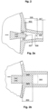
- Figure 1 shows a hydrocephalus valve 100 according to the invention in its construction in a schematic view from above. It shows a construction with a housing 200 in which an adjustment unit 700 in the form of a cam disk 704, a coupling element 400 and a body 500 are mounted.
- the housing also comprises an inlet 202 and an outlet 203.
- the movement of the cam disk 704 is centrally guided in the housing interior 201 by an axis 705, whereas the body 500 is not guided via its drilled body axis 502, but by means of its body surface 503.
- Figure 1 shows that the body 500 is shaped as a wedge, so that its body surface 503 tapers from a first body end 504 towards a second body end 505.
- Figure 1 also shows that the shape of the passage 300 is wedge-shaped or cup-shaped in cross section. Because the taper of the body surface 503 matches the taper of the passage, the wedge 506 is guided in the passage 300 along its body surface.
- the coupling element 400 is arranged with its first end 401 on the wedge 506 and with its second end 402 on the cam disk 704.
- the coupling element 400 can expediently be rigid or elastic.
- Figure 1 shows an embodiment with a rigid coupling element 400.
- This can be a pin or a plate.
- the cross section through the pin can be round, ellipsoidal or polygonal.
- the pin is a round metal or an edge metal made of titanium. Alternatively, it can also be made of Stainless steel, a duromer or a thermoplastic. Because the coupling element 400 is connected to the cam disk 704 and the wedge 506, a movement of the cam disk 704 leads to the movement of the wedge 506.
- the movement of the wedge 506 in the passage 300 results in a gap 600 between the outer surface of the wedge 506 and the inner surface 304 of the passage 300.
- the inner surface of the gap is the sum of the outer surface of the wedge 506 and the inner surface 304 of the passage from the beginning of the gap to its end. The larger the inner surface of the gap and the narrower the gap, the greater the friction of a fluid 900 that is to pass through the gap 600 or passes through the inner surface of the gap.
- the outer surface of the wedge 506 thus acts as a flow resistance/flow resistance, and so does the wedge 506.
- the flow resistance/flow resistance of the hydrocephalus valve 100 according to the invention can be adjusted by the adjustability of the gap length.
- the flow rate of the fluid per unit of time is adjusted via the flow resistance.
- a movable arrangement of the body 500 in the first passage direction 302 enables different, advantageous variants for producing a gap 600.
- This can mean that an angle exists between a direction of movement of the body 500 and its movement along a forced guide, which is determined, for example, by a linear bearing 405.
- the angle between the main direction of movement of the body and the first passage direction 302 is in other embodiments less than 80°, preferably less than 50°, in particular less than 20° or even smaller, i.e. less than 5°. In the embodiment, the angle is 0 degrees. So the main direction of movement of the body 500 is coaxial with the passage direction 302 and a symmetrical gap 600 forms as soon as the body 500 is spaced apart from the passage 300.
- the sections of the body 500 and the passage 300 facing each other are symmetrical.
- other geometric features of a body 500 can be changed in order to vary a flow resistance/flow resistance through the passage 300.
- the roughness of the outer surface of the wedge 506 can be changed or its shape.
- a spring seat 800 is incorporated into an edge of the passage 300.
- the spring seat 800 can be a pin onto which a spring 802, for example a spiral spring, can be pushed.
- the secure fit of a spring 802 facilitates its positioning between an edge of the passage 300 and the wedge 506, so that the spring force of the spring 802 presses the wedge 506 out of the passage 300 in the direction of the passage end 301.
- the distance 702 between a pivot point of the cam disk 704 and a reference point of the body 500 varies.
- cam disks 704 In addition to cam disks 704, other adjustment units can alternatively be used, which can also be moved translationally in their direction 701.
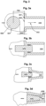
- Figure 1a shows a detailed view of Figure 1 , which represents two alternatives of a coupling element 400.
- Figure 1b shows a detailed view of Figure 1 , which represents an opening state of the hydrocephalus valve 100 (spring 802 not shown). In the open state, the second body end 505 touches the cross-sectional area 303.
- Figure 2a shows a detail with a preferred embodiment of a body with a gap.
- the preferred embodiment is based on the interaction of two components, a passage 300 and a body 500.
- Figure 2a shows that the passage 300 consists of a funnel-shaped inlet area 306 and a hose-like section 307.
- Figure 2a that a gap 600 exists between the two components when the body 500 was manufactured as a wedge 506.
- the wedge 506 can be machined from a titanium, steel or biocompatible elastomer block, for example.
- the Wedge 506 is milled out of a titanium block. Alternatively, it can also be cut out of a biocompatible plastic block.
- Moving the wedge 506 in or out of the funnel-shaped inlet 306 of the passage 300 varies the gap length 602 and thus the flow resistance between the wedge 506 and the passage 300.
- the wedge 506 seals against the passage 300 when the peripheral edge of the wedge face 507 strikes the transition edge 508 between the funnel-shaped inlet 306 and the tube-like section 307.
- Figure 2b shows a detail with an alternative embodiment of a body with a gap.
- the body 500 has the shape of a rod 509. The larger the gap length 602 and the smaller the gap width, the greater the
- the length of the rod 509 i.e. the maximum level of flow resistance, is adapted to the position-dependent weight of a volume of CSF in the gravitational field of the earth.
- the body 500 can be a sphere (not shown), a cone (not shown) or a cylinder (not shown).
- Figure 3a shows a detail with an alternative embodiment of a body with a gap, in which a gap 600 can be produced between an outer edge of a spherical body 500, such as a ball, and a bore.
- a spherical body 500 such as a ball
- the ball is positioned at a distance 702 in front of the bore.
- the bore acts as a passage 300, the distance between the outer edge and the bore edge forms the gap 600.
- the passage volume varies depending on the distance 702.
- Figure 3b shows a detail with an alternative embodiment of a body with a gap, wherein a gap 600 between a rod 509 and a bore creates the passage 300.
- Figure 3c shows a detail with an alternative embodiment of a body with a gap 600 which is made between a wedge 506 and a through hole 300.
- Figure 3d shows the example from Figure 3c in a closed state.
- the peripheral edge of the wedge end face 507 of a wedge 506 seals against the transition edge 508 of a passage 300 between the funnel-shaped inlet and the hose-like section.
- Figure 4 shows an alternative, second embodiment of the invention in a side view.
- a cam disk 704 and a body 500 are connected by means of a coupling element 400 in order to translate a rotation or a partial rotation of the cam disk 704 into a reduction or increase in the distance 702.
- This change corresponds to an adjustment of the gap 600 and, associated with this, an adjustment of the passage volume.
- the cam disk 704 is mounted on an axis 705.
- a gear member 403 for example a gear rod, is attached to the cam disk 704 and the body 500 at at least two different ends.
- the gear member 403 is attached to the cam disk 704 near the outer edge by means of a pin 404 at its second end 402.
- the other end, the first end 401 of the gear member 403, which has a through hole, is mounted in a mouth of the body 500.
- the cam disk 704 can be rotated, i.e. adjusted, via a magnetic coupling between the cam disk 704 and an adjustment tool (not shown).
- the flow resistance i.e. the size of the gap 600 or its passage volume
- the Drainage volume of the hydrocephalus valve 100 i.e. the desired outflow of a volume of CSF, can be adjusted.
- FIG. 5 shows an alternative, third embodiment of the invention in a side view.
- the hydrocephalus valve 100 comprises a cam disk 704 with an axis 705, a plug 406, a linear bearing 405, a spring 802 or any other spring element 801 and a passage 300.
- the spring 802 or the spring element is mounted in a spring seat 800.
- a rotation of the cam disk 704 via a contact point 703 between the cam disk 704 and the plug 406 is translated into its linear movement.
- the plug 406 is pressed against the cam disk by the spring during its movement.
- the plug 406 can be mounted by a linear bearing 405.
- the plug 406 is supported in one of its uniform sections.
- the plug 406 is turned from a block of material, in particular a block of titanium. The turning simplifies the manufacture of the plug 406 with five base sections, a contact section 408, a neck section 409, a collar section 410, an extension section 411 and a closure section 412.
- the spring 802 is supported in a spring seat 800, which is designed as a ring. The movement of the plug 406, e.g. in the form of a needle 1152, creates a gap 600, or a gap passage 1154, or a gap-like passage.
- FIG. 6 shows an alternative, fourth embodiment of the invention in a view from above.
- the hydrocephalus valve 100 shown comprises a cam disk 704, a sleeve 412 and an extended outlet 203 in the form of a tube 204.
- the tube 204 can be a tube, a piece of hose, a hose end, a pipe section or a flexible or rigid hollow body.
- the sleeve inner diameter 413 corresponds approximately to the pipe outer diameter 205.
- the diameters deviate further from one another so that a gap 600 is created between the sleeve 412 and the tube 204.
- the tube 204 runs with a first tube end 415 in the sleeve 412.
- Figure 7 shows a hydrocephalus valve 100 according to the invention with a coupling element 400 in a telescopic design in a side view, which is preferably based on the embodiment in Figure 6 based.
- the sleeve 412 is also made from a titanium block, namely milled, but a central plug 416 and an edge 417 are milled out.
- a round outlet bushing 308 is embedded coaxially with the passage 203 in the housing 200.
- the outlet bushing 308 can also be glued, inserted, screwed, pressed or melted coaxially with the passage 203 in the housing 200, on the housing 200 or by means of holding elements within the passage 300.
- the outlet bushing 308 is made in one piece from the housing 200, a housing cover or a housing pot.
- the sleeve 412 is guided in a linear bearing 405. The tip of one sleeve end touches the outer edge of the cam disk 705 at a contact point 703 or a contact line or a contact surface.
- a spring 802 is a compression spring in this embodiment, so that it presses the sleeve 412 out of the outlet 203, resulting in a gap 600 between the central plug 416 and the pipe 204 and between the edge 417 and the pipe 204 and between the edge 417 and the outlet bushing 308.
- the distance 702 between the cam disk 704 and the end of the coupling element describes the adjustability of the gap 600, or the gap passage as a possible adjustment parameter.
- the adjustability can thus be described mathematically by representing the relationship between the rotation of the cam disk 704 in its direction of rotation 701 and the change in the distance 702.
- the spring 802 is mounted in a spring seat 800.
- FIG 8 shows that in Figure 7 illustrated hydrocephalus valve 100 according to the invention with a rotor 706 and with magnetic coupling member 711 with magnets 707, a north pole 708 and a south pole 709.
- the adjustment unit 700 comprises several Parts, including a cam disk 704, a rotor 706 and a swivel arm 1050 or a rotor 706 with swivel arm 1050 or a cam disk 704 with swivel arm 1050.
- the cam disk 704 is mounted together with the rotor 706 on the axis 705 as an assembly.
- the rotor 706 comprises a swivel arm 1050 or can be designed as a swivel arm 1050.
- cam disk 704 and the rotor 706 are connected to one another. In a preferred embodiment, they are screwed, glued, welded or made from one piece.
- the connection between the rotor 706 and the cam disk 704 results in their joint rotation/swivel movement, so that a rotation of the rotor 706, or the swivel arm 1050 or an additional swivel arm 1050 corresponds to a proportional rotation of the rotor 704.
- the proportionality follows the offset of the cam disk 704 on the rotor 706.
- two stops 710 are introduced into the housing 200 in order to prevent a collision between the magnet 707 or rotor 706 and the spring 802 or sleeve 412.
- the size of the gap 600 between the outlet 203 and sleeve 412 can be adjusted by inserting them into the passage 300 or pushing them out of the passage 300 by means of a rotation/pivoting movement of the rotor 706.
- the sleeve 41 is pushed out of the passage by a spring 801, 802.
- the spring is held in its spring seat 800. This can be described by a parameterization of the distance 702.
- a brake 1000 is provided in the hydrocephalus valve 100 in order to secure a set angle of rotation of the rotor 706.
- the brake 1000 blocks the freedom of rotation of the rotor 706 or its swivel arm 1050.
- the brake 1000 blocks the rotor 706 by switching on and off a frictional connection between it and a rotor surface.
- the brake 1000 blocks by an electromagnetic force field fixing the rotor 706 in a desired position.
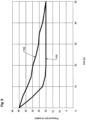
- Figure 9 shows a recording of the cerebrospinal fluid pressure over time on a conventional hydrocephalus valve with a spring-loaded ball as a closing device and with a conventional drainage line. This resulted in a pressure curve 1103.
- the pressure curve 1103 shows that a cerebrospinal fluid pressure of 40 cm water column (corresponds to 39.2266 mbar) was reduced to a normal level of approx. 20 cm water column (corresponds to 19.6133 mbar) within around 10 seconds.
- a large number of patients feel uncomfortable with this speed of pressure reduction.
- the pressure curve can only be achieved for different patients with different ventricular system sizes if it can be adjusted using structural parameters.
- the pressure reduction is spread over a maximum of 60 seconds, even more preferably over a maximum of 50 seconds.
- the pressure curve 1103 of the Fig.9 shows a course of the pressure curve over 50 seconds.
- the pressure curve 1103 plotted against time (abscissa) in seconds shows an inclination to the abscissa which is dependent on the scale for the pressure values (ordinate) and the scale for the seconds (abscissa).
- Everything which has an equal or lower inclination to the abscissa with the same scales for pressure values and seconds is within the scope of the invention, provided the inclination is not less than with a distribution of the pressure reduction over 60 seconds, preferably not less than with a distribution of the pressure reduction over 50 seconds.
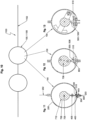
- Fig.10 shows a preferred embodiment of a variant of the inventive hydrocephalus valve as valve combination 1100.
- the adjustable valve combinations explained below are for electronic Control together with a pressure measurement (not shown) without any further auxiliary measures is able to produce a desired pressure curve 1103 ( Fig.9 ) .
- a desired pressure curve 1103 Fig.9
- the valve combination is shown schematically in Fig.10 shown. After Fig.10 it comprises a drainage line 1102. A conventional hydrocephalus valve and one of the subsequently inventive hydrocephalus valves 100 are installed in the drainage line 1102.
- Fig.10 the invention as an interconnection of a conventional valve with an inventive valve combination 1100, i.e. an extended valve combination.
- FIG 11 shows a hydrocephalus valve 100 according to the invention in a sectional view from above.
- Fig. 11 is a reduction of Fig.1
- the hydrocephalus valve 100 includes a liquid-tight housing 200, which is provided with an inlet 202 and an outlet 203.
- An axis 705 is arranged in the housing 200.
- a rotor 706 sits on the axis .
- the rotor 706 forms a cam disk 704 with a first cam track 712.
- a coupling element, a pin 400 slides on the first cam track 712 with its second end 402.
- the pin 400 is held between guides 405 of the housing 200 so that it can move in the radial direction to the axis 705.
- a body 500 in the form of a plug is provided on the opposite first end 401 of the pin 400.
- the body 500 has a conical tip and a collar 510. After Fig. 11 the collar 510 can seal tightly with a sealing surface 304 of the housing 200. This prevents an undesired leakage of liquor.
- the plug is pressed outwards in a radial direction by the cam track 712.
- the cam track 712 When the rotor 706 is pivoted counterclockwise in Fig . 11 the radius of the curved path 712 is reduced.
- the pin 400 remains in contact with the curved path 712. This occurs under the pressure of a spiral spring 803.
- the spiral spring 803 sits with one end in a recess in the conical tip.
- the spiral spring 803 is supported at the other end on a web 804 of the outlet 203.
- a passage for cerebrospinal fluid is formed between the stopper and the sealing surface on the housing.
- the cam disk 706 is firmly seated on the axle and the axle is connected to an electrical stepping motor (not shown).
- the stepping motor is activated by a storable control system.
- the control system contains a Fig.9
- the desired temporal progression of the pressure drop in the cerebrospinal fluid is stored. This progression is compared in the control system with the pressure values of a pressure measuring device (not shown) using an algorithm. The difference between the two values leads to a control pulse to the electric stepper motor.
- Figure 12 is a reduced representation of Fig.5 .
- the embodiment according to Fig. 12 differs from the embodiment according to Fig. 11 in that the body 500 is a wedge 506, or a wedge-shaped plug that protrudes into a suitable drain.
- Wedges 506 have a rectangular cross-section with two sides inclined towards each other and two sides parallel to each other.
- the wedge-shaped plug is like the plug according to Fig. 11 held in place by a pin not shown here. Even in the embodiment according to Fig.
- a spiral spring 803 is provided, which ensures a permanent contact of the pin with the cam disk. Unlike Fig.1 the spiral spring 803 is not located on the tip of the plug, but on the pin, with a collar 510 sitting on the pin. The spring is located between the collar and the inner wall of the housing, with the spring surrounding the pin and the plug.
- the wedge-shaped plug has a different rotary and swivel drive, namely a rotor 706, like a conventional hydrocephalus valve, together with a conventional locking mechanism between two adjustment processes.
- the rotor is particularly often moved with magnets, one part of which is built into the rotor and the other part is arranged in an adjustment device that is placed on the patient's skin above the implanted valve and releases the locking mechanism when pressed and swivels the rotor when rotated.
- the valve thus created is Fig.10 combined with a conventional hydrocephalus valve
- Fig. 10 and Fig. 12 show a drainage line 1101 ( Fig.10 ) with an inventive hydrocephalus valve 100 which is intended for adjusting a drainage rate and is connected downstream of a conventional hydrocephalus valve in the drainage line 1101.
- Figure 13 is a reduced representation of Fig.8 .
- Fig. 13 shows a situation in which the housing wall is at a distance from the swivel arm 1050. The distance is created when the adjustment device for adjusting the cam disk is pressed onto the top of the implanted housing. This deforms the housing so that the swivel arm 1050, which previously rested frictionally on the housing inner wall, is released for adjustment. Successful release is signaled by a clicking sound because the upper part of the housing is designed as a cracking membrane, i.e. a stepped round membrane (not shown). Preferably, a plurality of steps are made in the round membrane (not shown) for this purpose.
- the body 500 with collar 510 is designed as a stepped cover.
- Figure 11 , Fig. 12 and Fig. 13 also show a body 500 which in each position has a distance to the surrounding inlet or outlet.
- the body is indirectly in contact with a cam disk 704.
- contact is made with a thickened extension of the body 500.
- the collar 510 shown is shown at the transition of the body 500 to its extension.
- the spring designated 802 is arranged between the collar 510 and the inner wall of the housing.
- the spring 802 surrounds a body 500, here a plug, and engages in a centering groove.
- two magnets described are embedded in the cam disk 704 ( Fig. 12 ).
- a combination (not shown) with the embodiment of Fig.4 results in a body that is designed as a spherical plug.
- the diameter of the spherical plug is larger than the opening width of the inlet or outlet, so that the spherical plug can both act as a valve with an open-close function and also adjust the opening width.
- the spherical plug is held so that it can be moved in a guide using a rod.
- the spherical plug is articulated to a pivoting rotor in the valve housing using an articulated rod.
- magnets in the rotor and an adjustment device are provided for adjusting the spherical plug, which also has magnets and is placed on the patient's skin above the implanted valve and turned/pivoted by hand.
- a storable stepper motor can also be used instead of the adjustment device.
- the spherical plug can be brought into any desired position using a stepper motor.
- a combination (not shown) with the embodiment of Fig.6 creates another valve with a body designed as a pot-shaped plug, whereby the pot-shaped plug sits above an outlet protruding into the valve housing.
- the pot-shaped plug is also adjusted with a cam disk.
- the pot-shaped plug is like the plug after Fig.6 in a form not shown in the valve housing and held in contact with the cam disc by a spring. This plug offers the same application possibilities as the cylindrical plug according to Fig. 3b . While after Fig.
- the remaining gap between the cylindrical plug and the surrounding tubular inlet or outlet forms the limit value for the cerebrospinal fluid flow
- the remaining gap (limit value) between the tubular outlet or inlet and the inner casing of the surrounding cup-shaped plug is decisive.
- Opening movements of the plug remain without influence even in the embodiment if they exceed the limit value for the opening cross-section.
- a combination (not shown) with the embodiment of Fig.7 shows a valve that also includes a cylindrical plug.
- the cylindrical plug has an adapted tubular outlet.
- the tubular outlet surrounds the cylindrical plug at a selected distance.
- the cylindrical plug has a collar and a thickened extension in the radial direction to a cam disk.
- the extension touches the cam disk.
- the extension is rounded at the point of contact.
- the cylindrical plug is held on the extension in a guide of the housing so that it can be moved radially.
- a spiral spring between the collar and the inner wall of the housing ensures that the plug always remains in contact with the cam disk.
- the opening gap between the collar and the outlet is adjusted by moving the cam disk. If the opening gap is reduced, the cam disk pushes the collar outwards.
- the cam disk makes room so that the plug follows the curved path of the cam disk under the pressure of the spiral spring.
- the cam disk is pivoted using magnets, with magnets both in the cam disk and in an adjustment device which is placed on the patient's skin above the implanted valve and rotated for adjustment.
- an annular web on the collar and an annular web on the inner wall of the housing are provided concentrically to the cylindrical plug and the outlet. These webs force the liquor to meander along its flow path.
- the embodiment differs in that it has a swivel arm on the cam disk. The swivel arm is used to hold the magnets.
- a different guide for the plug is provided in the valve housing.
- a preferred shape of the aforementioned body has the shape of a needle.
- Fig. 2a, 2b , 3a and 3b show different bodies. Except for Fig. 2b These are conical plugs for a valve, whereby the plug has a tip that is thicker than the opening of the inlet or outlet for the cerebrospinal fluid.
- the conical plug can also be understood as a needle.
- the embodiment as a needle is part of each of the aforementioned embodiments, eg according to Fig. 11 , Fig. 12 and Fig. 14 .
- Fig. 3c shows the open position of the valve
- Fig. 3d the closed position.
- the plug to the Fig. 3c and 3d The valve corresponds to the Valve after Fig. 2a.
- Fig. 2b shows a precisely cylindrical plug instead of conical or wedge-shaped plugs.
- the cylindrical plug includes a matching tubular inlet or outlet on the valve which surrounds the plug at a distance. No matter how far the cylindrical plug is moved into the inlet or outlet, the distance between the plug and the surrounding inlet or outlet remains unchanged.
- the cylindrical plug is suitable for a valve which otherwise has the characteristics of the Fig .
- the cylindrical plug is also suitable for drainage with a single valve in the drainage line and at the same time reducing the pressure drop as described above.
- the cylindrical plug and the matching tubular inlet or outlet take the place of the usual ball and the usual valve seat for the ball.
- a collar is attached to the cylindrical plug as shown in Fig.1 provided.
- the collar has a closing function.
- the collar closes against the inner wall of the valve housing.
- a spring rests on the cylindrical plug, which determines the opening pressure of the valve.
- the spring is adjustable in the conventional way, so that the opening pressure is also adjustable. The higher the cerebrospinal fluid pressure, the further the collar moves away from the closing surface of the inner wall of the valve housing. However, this only leads to a larger opening width of the valve up to a limit.
- the opening width cannot be larger than the gap between the plug and the surrounding inlet or outlet.
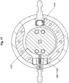
- Fig. 14 to 18 show a preferred embodiment of the invention. This embodiment can also be carried out independently.
- Figure 14 shows a section through a device 100 according to the invention with two valves in a common housing, a valve combination 1100.
- the housing with the two valves is part of a cerebrospinal fluid drainage or a shunt of a hydrocephalus patient.
- the valve combination 1100 is connected to corresponding lines (not shown), so-called catheters under the skin of the Patients are implanted in the form of a cerebrospinal fluid (CSF) implanted in the patient's body.
- CSF cerebrospinal fluid
- the housing consists of a base 1110, a ring 1111, an annular support disk 1112 and a cover 1113.
- a displaceable axle 1120 is located in the middle of the housing.
- the axle 1120 is held at one end in the support disk 1112 and at the other end in a guide 1114 of the base 1110.
- the axle 1120 has an outer collar 1121 and is supported by the outer collar 1121 on the base 1110 via a spiral spring 1122.
- a rotor 1130 and a locking ring 1131 are also located on the axis 1120.
- the rotor 1130 engages with an inner collar 1132 between the outer collar 1121 and the locking ring 1131.
- the rotor 1130 also surrounds the spiral spring 1122.
- a corresponding recess 1133 is provided in the rotor 1130.
- the spiral spring 1122 presses the rotor 1130 against the support disk 1112 in the housing so that there is frictional engagement between the rotor 1130 and the support disk 1112 and the rotor 1130 is locked in the relevant position.
- the cover 1113 has an outward-facing curvature.
- the lock can be released by pressing against the housing with an adjustment device that is placed above the housing on the patient's skin.
- the brake can also be released by manually pressing the cover 1113.
- the pressure causes the cover 1113 to dent and the axis 1120 to shift against the base 1110.
- the axis 1120 can thereby shift into the cavity 1115 of the guide 1114. Even a slight shift of the axis 1120 causes the rotor 1130 to become detached from the support disk 1112.
- the rotor 1130 can then be pivoted.
- magnets 1134 are installed in the rotor 1130 at diametrically opposite locations.
- Figure 14 shows a situation of an invention 100, 1100 with a ball 1141 when the valve is switched off.
- the ball 1141 is pressed against a valve seat by a disc spring 1147.
- Fig . 14 shows a second insert 1151.
- a body 500, 1152 in the form of a cylindrical closing part 1152, e.g. in the form a needle 1152 is arranged so that it can move.
- the needle 1152 projects with a conical tip 1153 into the gap passage 1154, a small channel, a gap. The position of the tip 1153 determines the opening width of the gap passage 1154 for the passage of cerebrospinal fluid.
- the position of the tip 1153 or the closing part 1152 is also determined by a second cam track 714 on the rotor 1130.
- a body 500 i.e. the needle 1152
- the second curved path surface 715 is formed by the contact surface of the needle 1152 with the rotor 1130.
- the first curved path surface 713 is formed by the contact surface of the ball 1141 and the first curved path 712.
- the rotor 1130 is mounted on an axle 1120.
- An outer collar 1121 of the axle 1120 supports the inner collar 1132 of the rotor 1130 and is held by a locking ring 1131.
- the axle 1120 sits in a recess 1133 of the rotor 1130.
- the closing part 1152, the needle 1152 is constantly in contact with the rotor 1130, so that the needle 1152 constantly follows the curved path 715 intended for it.
- the needle 1152 is surrounded by a spiral spring 1155, which presses the needle 1152 against the rotor.
- the spiral spring 1155 is supported with one end in the insert 1151. With the other end, the spiral spring presses against the needle 1152.
- Figure 15 shows the invention according to Fig. 14 with the same sectional view but with a different pivoting position of the rotor 1130, in an open state.
- the spiral spring 1155 pushes the needle 500, 152 out of the gap passage 1154 so that the channels 1117 can be flowed through by liquor.
- there are suitable magnets 1134 in the adjustment device so that a rotation of the Adjustment device around the axis 1120 in its guide 1114 causes the rotor to pivot via the attractive force of the magnets 1134. If the adjustment device is removed again after a desired pivoting, the rotor is automatically locked again.
- a gravitational valve 1140a (not shown) or a differential pressure valve 1140b in the housing can be switched on or off.
- the gravitational valve 1140 or the differential pressure valve 1140b is arranged on the inlet side of the housing.
- the direction of flow is designated 1146.
- the gravitational valve 1140a or the differential pressure valve 1140b includes a ball 1141.
- the ball 1141 sits in an insert 1142 in its valve seat 1116.
- the insert 1142 protrudes with a connecting sleeve 1143 through an opening in the ring 1111 of the housing.
- the connecting sleeve 1143 is used to connect a hose line.
- the Fig. 15 shows the differential pressure valve 1140b open with the patient lying down.
- the rotor 1130 presses with a first contact surface, first cam track surface 713, against the outer wall of the ball so that it is displaced against the spring force of a disc spring 1147 in the first insert 1142 in the direction of the opening 1144. This displacement frees up channels 1117 so that incoming liquor can pass through. Because channels 1117 lead through the housing, the liquor can flow through the invention.
- a gravity valve 1140a In the event that a gravity valve 1140a is installed and the patient is Fig. 15 When the patient assumes a standing position in the valve position shown, the gravity valve 1140a closes under the pressure of the ball 1141. Independently of this, the gravity valve 1140 can be switched off so that a flow of cerebrospinal fluid is always prevented, even when the patient is lying down.
- the Figures 14 and 15 show different positions of the locking part 1152.
- the second cam track 714 for the closing part 1152 with the rotor 1130 runs in Fig. 14 at the contact surface at a distance from the axis 1120 sufficient for the position of the tip 1153.
- the distance of the contact surface from the axis 1120 is considerably smaller, so that the tip 1153 can be moved by this amount compared to the position according to Fig. 14 is set back and a larger opening width results between the tip 1153 and the gap passage 1154. Therefore, Fig. 15 the invention in an open state.
- Figure 16 shows a section through the device according to the invention, wherein the central axes of the inserts 1142 and 1151 lie in the section plane.
- the closing part 1152, the needle 1152, is only partially visible in the sectional view because it is at a distance from the cutting plane.
- the ball 1141 is shown in the closed position.
- the rotor 1130 has a concavity 1135 and a concavity 1136.
- the ball 1141 In the area of the concavity 1136, the ball 1141 is in the closed position.
- the gravity valve 1140a or differential pressure valve 1140b is switched off.
- the gravity valve In the area of the concavity 1135, the gravity valve is switched on again. With step-by-step switching, even less deep concavities and/or less strong concavities are provided between the concavity 1135 and the concavity 1136.
- Fig. 16 shows in the embodiment four magnets 1134 for the rotor 1130 for its adjustment.
- Figure 17 shows a section through the device according to the invention, wherein the center axis of the closing part 1152 lies in the cutting plane.
- the cutting plane runs through the second curved path 714 belonging to the closing part 1152. It can be seen that the second curved path 714 belonging to the closing part 1152 runs in a spiral shape, so that a continuous adjustment of the closing part 1152 is possible between two extreme values.
- one valve is arranged at the inlet 202 of the housing and the other valve is arranged at the outlet 203 of the housing.
- valves in a housing according to the invention are also possible. These include combinations of gravitational valves with valves other than differential pressure valves, as well as differential pressure valves with valves other than gravitational valves. Valves other than differential pressure valves also include cam-controlled valves.
- a cam track is guided along a closing part. The cam track determines the opening and closing position of the closing part.
- the closing part can be guided in a form-fitting and/or force-fitting manner.
- a groove in a rotor into which the closing part engages with a pin or the like is both form-fitting and force-fitting within the meaning of the invention.
- the form-fitting and force-fitting connection can also be formed by a rail as a cam track, which is surrounded by the closing part.
- a force-fitting connection is provided between the cam track and the closing part.
- the force-fitting connection is formed by a spring, with which the closing part is pressed or pulled against the cam track.
- the closing part is at least partially designed as a profiled bar and is held displaceably in a guide or is connected to a profiled bar that is held displaceably in a guide.
- a cylindrical profiled bar is provided, one end of which presses against the curved track under spring pressure and the other end of which corresponds to a valve seat.
- the valve seat can be a ring or a hole in the housing. The hole can widen towards the closing part. The widening can be conical or have a different outer surface.
- the body i.e. a needle 1152
- the second insert 1151 is arranged in the second insert 1151, so that the second insert 1151 can be installed in the housing together with the needle 1152.
- the second insert 1151 forms a connection for a drainage line.
- the insert protrudes into the housing interior.
- the second insert 1151 forms the guide for the cylindrical closing part, the needle 1151.
- the second insert 1151 can form a cavity in which the spiral spring 1155 surrounds the cylindrical closing part 1152.
- a bore 1156 can be made transversely to the longitudinal axis in the area of the tip of the second insert described above, so that the cerebrospinal fluid can flow in or out past the tip transversely to the longitudinal direction of the insert.
- the cylindrical closing part 1152 slides on a second curved track 714. The closing part 1152 is pressed against the second curved track 714 by a surrounding spiral spring 1155, so that the closing part 1152 follows every change in the second curved track 714.
- the second cam track 714 can be located on the front surface and/or on the casing of a rotor 1130.
- a disk-shaped rotor 1130 is used, the peripheral surface of which is designed as a second cam track 714 so that the closing part 1152 carries out all desired closing movements and opening movements. This is referred to as cam disk 704.
- the rotor/cam disc is pivotally mounted on an axis in the valve housing.
- the rotor/cam disc is preferably adjusted using magnets.
- magnets are mounted in the rotor/cam disc on the one hand and an adjustment device with other magnets is provided on the other.
- the adjustment device is placed on the patient's skin over the housing according to the invention and rotated. When the adjustment device is rotated, the rotor/cam disc follows the magnetic force or adjustment force of the adjustment device. After each adjustment, the rotor/cam disc is locked in the position reached until the next adjustment. The locking is done either by clamping the rotor/cam disc. The clamping can be done on the circumference or on the front surface of the rotor/cam disc.
- the housing can be used for clamping on the circumference by using a housing with a flexible cover and flexible side walls so that the side walls bulge outwards when pressure is applied to the housing cover and release the rotor. When the pressure is released, the housing returns to its original shape and encloses the rotor/cam disc between the side walls.
- the pressure required to deform the housing is generated by the adjustment device.
- the adjustment device is therefore first pressed against the housing cover to release the locking mechanism before pivoting takes place.
- an axially adjustable axle is preferably provided in the housing.
- the axle is under the pressure of a spring which presses the rotor frictionally against a cover that is slightly curved outwards.
- the certain amount is a slight curvature of the cover inwards.
- the rotor can then be rotated in the manner described above.
- the pressure is generated with the adjustment device in the same way as with a locking device on the circumference; the same applies to the rotation.
- the displacement is possible in the housing because there is a corresponding amount of play between the end of the axle and the bottom of the housing.
- the axle has a collar with which it engages behind the rotor, which is designed as a cam disk.
- the spring with which the locking pressure is applied to the rotor/cam disk via the axle and its collar, is arranged between the housing bottom and the collar of the axle.
- a ring can be mounted on the side of the rotor facing the cover, which forces the rotor to lift off the cover if the cover deforms inwards. The ring is attached to the rotor or to the axle.
- the differential pressure valve described above can be combined with other valves.
- the differential pressure valve can be arranged in front of or behind the other valve in the direction of flow/drainage.
- the valve described above can be used to dampen the drainage speed, i.e. to even out the pressure drop over a certain period of time.
- Gravity valves are preferably used as other valves.
- gravity valves can be conventional valves described above.
- the gravity valve opens maximally in the lying position.
- the pressure drop can be advantageously equalized, i.e. made adjustable for each patient.
- a special gravity valve namely a switchable gravity valve
- the gravity valve can be switched on and off.
- an actuating device/switching device is preferably provided in operative connection with the closing part of the gravity valve.
- the length of the indentations on the rotor/cam disk on the circumference or on the front surface of the rotor/cam disk results from the adjustment range desired for the second valve.
- the gravity valve described above can also have advantages for CSF drainage regardless of its combination with a second valve. This means that the gravity valve described can also be advantageous as a sole valve for regulating CSF flow.
- cam tracks are then provided on the common rotor/cam disc, one of which is intended for one valve and the other for the other valve.
- the two cam tracks are then preferably in different planes that are parallel to one another. However, both cam tracks can also be in a common plane.
- the cam tracks then preferably extend over different circumferential surfaces.
- the rotor/cam disc After swivelling/rotating the rotor/cam disc, the rotor/cam disc is locked in place so that unintentional adjustment is avoided. The lock is released before adjustment and engages again after each adjustment. Such an adjustment can be achieved with different designs.
- gearing is provided on the housing and the rotor. When the gearing meshes, the rotor/cam disk is blocked. The blockage is released by moving the gearing apart.
- Other embodiments are based on the housing being frictionally engaged with the rotor/cam disk in the locking position.
- the housing is deformed so that it lifts off the rotor/cam disk.
- the deformation required to release the locking is preferably carried out using the adjustment device for rotating the rotor.
- the adjustment device is not only placed on the patient's skin over the implanted valve, but is also pressed against the valve until the locking is released by deformation of the housing. After the adjustment device is lifted off, the housing automatically returns to its original shape and engages the locking.
- Figure 18 shows a preferred embodiment of a rotor in a top view. Two different steps can be seen, each outer edge of which is a curved path.
- the lower step is characterized by a first curved path 712, the upper step by a second curved path 714.
- a bulge 1135 is embedded in the lower step, and a bulge 1136 can be seen.
Landscapes
- Health & Medical Sciences (AREA)
- Engineering & Computer Science (AREA)
- Biomedical Technology (AREA)
- Neurology (AREA)
- Ophthalmology & Optometry (AREA)
- Otolaryngology (AREA)
- Anesthesiology (AREA)
- Heart & Thoracic Surgery (AREA)
- Hematology (AREA)
- Life Sciences & Earth Sciences (AREA)
- Animal Behavior & Ethology (AREA)
- General Health & Medical Sciences (AREA)
- Public Health (AREA)
- Veterinary Medicine (AREA)
- External Artificial Organs (AREA)
Description
- Die Erfindung betrifft ein Hydrocephalusventil zum Abfluss von Fluid aus Ventrikelsystemen von Patienten, dass mindestens ein Gehäuse mit Gehäuseinnenraum, mindestens einen ersten Durchlass zum Einlassen und/oder Auslassen umfasst, mit mindestens einem Körper, welcher im Gehäuseinnenraum angeordnet ist, wobei der Körper mindestens in einer Richtung bewegbar ausgebildet ist und das mindestens eine Einstelleinheit aufweist.
- Hydrozephalus Patienten haben folgendes medizinisches Problem:
Das Gehirn ist im Schädel umgeben von einer besonderen Flüssigkeit, dem Liquor. Dieser Liquor wird ständig produziert und im gleichen Maße resorbiert. Bei der Erkrankung des Hydrozephalus, auch Wasserkopf genannt, ist dieses Gleichgewicht gestört. Da der Schädel ein geschlossenes Gefäß darstellt, kommt es zu einer Vergrößerung, wenn mehr Liquor produziert als resorbiert wird. Durch die Vergrößerung können beim Säugling die Schädelnähte nicht zusammenwachsen, beim Erwachsenen steigt der Schädelinnendruck. Es gibt also ein Alters- und Kinderhydrozephalus. - Hydrozephalus lässt sich in seinem Formen in Hydrocephalus internus, Hydrocephalus externus, Hydrocephalus externus et internus, Normaldruckhydrocephalus und Hydrocephalus e vacuo unterscheiden.
- Die Behandlung eines Hydrozephalus erfolgte ursprünglich durch die bloße Ableitung des Liquors. Dies geschah durch die bloße Schlauchverbindung zwischen dem Schädel und einem großen venösen Blutgefäß oder durch eine entsprechende Verbindung des Schädels über einen Schlauch mit dem Bauchraum. Bald erkannte man jedoch, dass der Druck im Schädel einen bestimmten physiologischen Wert besitzen muss, wenn nicht wieder andere Komplikationen auftreten sollen.
- Moderne Therapien des Hydrocephalus nutzen eine implantierbare Drainage, eine künstliche Verbindung zwischen den Hirnkammern im Kopf und einem Ableitungskompartiment, heute meistens dem Bauchraum zur Einstellung eines bestimmen physiologischen Werts.
- Es sind verschiedene Drainagen bekannt mit denen der Druck im Schädel eines Patienten therapiert werden kann. Die Drainagen sollen sich bei einem bestimmten kritischen Druck öffnen und den Abfluss von Liquor -auch Cerebrospinalflüssigkeit genannt- freigeben, so dass eine Bildung eines Überdrucks im Schädel verhindert wird. Üblicherweise werden diese Drainagen zum Schutz vor einem Überdruck an Cerebrospinalflüssigkeit (CSF) als sogenannte Shunts oder Ableitungen bezeichnet.
- Kern der implantierbaren Drainage ist ein implantierbares Ventil, mit dem die Drainage gesteuert wird. Dieses Ventil wird als Hydrocephalusventil bezeichnet. Die Hydrocephalusventile werden regelmäßig dicht unter der Haut eingepflanzt. Derartige Drainagen werden im Allgemeinen im Bereich des Kopfes unter der Haut implantiert.
- Eine mögliche Definition des Begriffs Shunts ist nach Miethke: jede künstliche hydraulische Verbindung zwischen einem ersten Körperteil, das Cerebrospinalflüssigkeit enthält und einem zweiten Körperteil, welches selbige aufnehmen kann, vgl. The Cerebrospinal Fluid Shunts, Seite 130/131, (Quelle 1). Zum Thema Hydrozephalus sind weitere Quellen das Buch Normal Pressure Hydrozephalus, Fritsch et al., 2014 (Quelle 2) sowie die Normen EN ISO 7197 (Quelle 4) und EN ISO 1463 (Quelle 5).
- Alle Quellen enthalten u.a. Fachbegriffe und Definitionen zum Thema Hydrocephalus. Ferner enthalten sie bekannte Wirkprinzipien und deren Gruppierung.
- Miethke schlägt in Quelle 1 eine zweifache Gruppierung vor, vgl. dazu Tabelle 1. In einer ersten Untergruppierung unterteilt er Ventile nach ihrem Wirkprinzipien in Differenz-Druckventile und Hydrostatische Ventile. In einer zweiten Untergruppierung differenziert er Ventile nach klinischen Funktionen, in feste, also nicht einstellbare und einstellbare Ventiltypen.
Tabelle 1: Wirkprinzipen von Shunts, Quelle 1, Seite 117 Ventil Fest Einstellbar Differenz-Druckventile Silikonschlitzventile X Membranventile X Kugelkonusventile X X Hydrostatische -Ventilprinzipien Anti Siphon Device Prinzipien X Fluss reduzierende Prinzipien X Gravitationsbasierte Prinzipien X X - Die Ventile der Gruppe des hydrostatischen Ventilprinzips sind nach Miethke als Ventile oder Ventilkomponenten bezeichnet, deren Konstruktionsziel in einem Verhindern einer Überdrainage begründet (Quelle 1, Seite 67). Ziel der Ventile dieser Gruppe ist dabei eine in Richtung einer Ventilöffnung wirkende Kraft eines hydrostatischen Drucks auszugleichen (sogenanntes Counterbalance).
- Ventile mit hydrostatischem Wirkprinzip können in drei Ventilarten differenziert werden. Deren Bezeichnungen sind Anti-Siphon-, flusskontrollierte- und gravitationskontrollierte Geräte. Allen drei Ventilarten ist ein Differenzdruck gemein. Dieser berechnet sich aus der Differenz zwischen dem Druck hinter dem Ventil abzüglich des Drucks vor dem Ventil (Δp = phinter dem Ventil - pvor dem Ventil). Die Druckdifferenz, welche einen Volumenstrom durch das Ventil freigibt, wird als Öffnungsdruck des Ventils definiert.
- Anti-Siphon Geräte passen ihren Öffnungsdruck an die Höhe einer im Ventil angreifenden Saugkraft an. Gravitationskontrollierte Geräte passen den Öffnungsdruck an ihre Inklination im Gravitationsfeld der Erde an. Flusskontrollierte Geräte hingegen, passen den sie passierenden Volumenstrom an die Druckdifferenz an.
- Ähnliche Bezeichnungen für Volumenstrom anpassende Ventile im Stand der Technik sind flussratenabhängige-, flussregulierende- oder flussreduzierende Ventile oder Geräte. Dabei ist der Begriff Fluss im Allgemeinen dem Begriff Volumenstrom, Volumen pro Zeit gleichzusetzen.
- Jedes Hydrocephalusventil ist durch eine Kennlinie gekennzeichnet. Dr. med. Alfred Aschoff beschreibt Kennlinien in In-Vitro-Testung von Hydrozephalus Ventilen, 1994, Seite 32 (Quelle 7). Er nimmt ihre Diskussion darin auf, weil Shuntventile Strömungsregler mit unidirektionaler Richtungsbevorzugung sind. Sie zeichnen sich nach Aschoff dadurch aus, dass sie erstens durch eine unidirektionale Wirkung, zweitens durch einen Öffnungs- und Schließcharakteristik und drittens durch eine spezifische Druck-Fluss-Kennlinie charakterisiert sind. Die Druck-Fluss-Kennlinie ist üblicherweise nichtlinearer. Ihr Verlauf hänge nach Aschoff vom Hydrocephalusventil selber ab, so dass eine Hydrocephalusventil nur durch eine Angabe der vollständigen Kennlinie beschrieben werden kann.
- Nicht einstellbare Hydrocephalusventile sind durch eine Ventilkennlinie gekennzeichnet, hingegen einstellbare durch mehrere Ventilkennlinien.
- Bei den nicht einstellbaren Hydrocephalusventilen ist evident, dass Ventile der Gruppe des hydrostatischen Ventilprinzips in Abhängigkeit vom Liquordruck einen bestimmten Volumenstrom, eine Durchströmung zeigen. Wenn zu jedem Liquordruck ein zugehöriger Volumenstrom in einer Grafik aufgezeichnet wird, ergibt sich eine Ventilkennlinie.
- Bei den einstellbaren Hydrocephalusventilen konfiguriert jede Einstellung das Ventil. Jede Konfiguration ergibt eine andere Ventilkennlinie. Im Folgenden sind einige bedeutsame Hydrocephalusventile beschrieben:
-
JP2006020905 (Kaneka Medix Corp - Die
US 8870809 B2 (Christoph Miethke GmbH & Co KG ) betrifft ein implantierbares Hydrocephalussystem zur Behandlung von Hydrocephalus Patienten mit Medikamenten. Die Druckschrift zeigt ein implantierbares Hydrocephalussystem, mit dem auch Medikamente in den Patienten verbracht werden können. Dazu sind die Medikamente in einen Hohlraum, eine Kavität des Hydrocephalussystems abzugeben, so dass sie von dort durch einen Ventrikelkatheter in die Gehirnventrikel hydraulisch verbringbar sind. Nach der Lehre ist dazu ein System notwendig, dass in einem Zustand medikamentöse Flüssigkeiten aufnimmt, und diese in einem anderen Zustand in Richtung der Gehirnventrikel verbringt. Das System setzt damit ein Ventil voraus und umfasst daher ein Ventil Arrangement mit einer Ventilklappe in einem Gehäuse mit einem Einlass und einem Auslass. Das Ventil Arrangement im Ventil öffnet oder schließt den Einlass des Hydrocephalussystems in Abhängigkeit des medikamentösen Flüssigkeitsdrucks in der Kavität. - Die
DE 38 35 788 A1 lehrt gemäßEP 1 523 635 B1 Absatz [0003) (Aesculap AG) ein schnell, schaltendes Kugelventil. In einem Zustand wird medikamentöse Flüssigkeit aufgenommen und in einem anderen Zustand in Richtung der Gehirn abgegeben Im geschlossenen Zustand des Ventils wird die Kugel gegen die Durchlassöffnung gepresst. Zur Freigabe der Durchlassöffnung stößt der Betätigungsmechanismus die Kugel seitlich von der Durchlassöffnung weg. Hierzu gibt ein Betätigungselement des Betätigungsmechanismus einen seitlichen Stoß auf die Kugel, die sich daraufhin von der Durchlassöffnung bzw. dem Ventilsitz der Durchlassöffnung löst. Als Betätigungsmechanismus zum Verschieben der Kugel wird dabei ein impulsgetriebener Elektromagnet eingesetzt, der nach einer Betätigung durch eine Federkraft wieder in die Ausgangsposition zurückgezogen wird. - Die
EP 1 523 635 B1 (Aesculap AG ) bietet eine Lösung an, um ein Ventil bereitzustellen, dass Betätigungswege im Millimeterbereich ermöglicht. Dem Prinzip nach kombiniert der Vorschlag einen Grundkörper mit einer Durchlassöffnung und zwei drahtförmigen Elementen, insbesondere SMA- Drähten (ShapeMemory-Alloy) Diese verkürzen sich wechselseitig in Abhängigkeit einer Temperaturveränderung. In einer besonders vorteilhaften Ausgestaltung resultiert ein Ventil mit binärer Öffnungscharakteristik. Phenomenologisch resultiert eine Funktion eines Schalters aus einer Positionsmanipulation eines Körpers vor einer Durchlassöffnung. -
US 2015 0182 734 A1 (Christoph Miethke GmbH & Co. KG ) offenbart ein einstellbares Hydrocephalusventil, programmierbarer Gravitationsassistent, zur Druckeinstellung im Cranium eines Hydrocephalus-Patienten. Mittels einer Membran wird dazu eine Bremse gelöst, um einen Rotor freizugeben, so dass dieser frei um eine Achse rotiert werden kann. Die Membran meldet durch ein akustisches Signal, einem Klicken die Freigabe oder Blockade des Rotors an einen Nutzer. Weil in ihm Magnete verbaut sind, ist der Rotor mittels eines ebenfalls magnetischen Werkzeuges um seine Achse rotierbar. Die Rotation wird ausgenutzt um eine Ventilcharakteristik einzustellen. Das Ventil hat sich bewährt. - Die
US 4676772 (Cordis-Cooperation ) lehrte schon 1985 ein System zur Druckkontrolle von Cerebrospinalflüssigkeit. Dieses umfasst ein implantierbares Druckentlastungsventil für Fluide, welches ein Gehäuse und eine Einstelleinheit aufweist, um den Öffnungsdruck des Druckentlastungsventils einzustellen. In Abhängigkeit eines am Druckentlastungsventil anliegenden Drucks wird dabei eine Membran ausgelenkt, so dass ein Durchlass zwischen einem in der Membran eingelassenen Dichtring und einer Kugel geöffnet wird. Die Kugel ist dafür in einem Topf gelagert, in dessen Mantelfläche ein Gewinde geschnitten ist. Mittels des Gewindes ist der Topf in einen Deckel hinein- oder herausschraubbar, so dass ein Druck zwischen der Kugel und dem Dichtring einstellbar ist. Die Lage des Topfes, also die Anzahl eingeschraubter Gewindegänge ist im Druckentlastungsventil, kann über eine magnetische Brücke auf eine Anzeigevorrichtung wiedergegeben werden. - Die
US 4676772 lehrt zusammenfassend eine Einstellung eines Ventilöffnungsdruckes, nachteiliger Weise hingegen nicht die Einstellung eines definierten Volumenstroms. Zudem weist die beschriebene Technik den Nachteil auf, dass ein Einstellen eines Ventilöffnungsdruckes durch Einschrauben eines Topfes eine plastische Verformung der Membran nach sich ziehen kann. Diese tritt auf, wenn durch ein zu starkes Einschrauben des Topfes über die Kugel eine Kraft auf die Membran aufgebracht wird, die jenseits der Elastizitätsgrenze der Membran ist. Ein präzises Einstellen eines Ventilöffnungsdrucks setzt ein präzises Positionieren des Topfes im Deckel voraus. Der Topf wird im Deckel über eine magnetische Brücke verdreht, die einer Handbewegung eines Anwenders entspricht. Der Anwender erhält allerdings kein Feedback über die Reibung oder die relative Position zwischen Topf und Deckel. Somit wird der Topf im Deckel auf Grund eines Über- oder Unterverdrehens durch den Anwender nicht präzise positioniert, so dass der Ventilöffnungsdruck nicht präzise einstellbar ist. - Das sogenannte Orbis-Sigma Ventil wurde von Sainte-Rose, Hooven und Hirsch in: A new approach in the treatment of hydrocephalus, Neurosrg, 1987, 66(2), 213-26, vorgestellt. Das Orbis Sigma Ventil umfasst eine Saphir Membran mit einer Bohrung sowie einen durch diese Bohrung durchstechenden Stift bzw. Pin. Dabei weist der Stift in seinem Querschnitt einen Hinterschnitt in Richtung seines membranzugewandten Endes auf. Die Membran ist entlang ihres Umfangs in einem Gehäuse in einem Strömungskanal gelagert. Der Stift ist an seinem membranabgewandten Ende im gleichen Gehäuse und gleichem Strömungskanal gelagert. Liegt ein Differenzdruck über der Membran an, weicht diese aus, in dem sie sich mit dem Druckgradienten wölbt. Die Stärke der Wölbung und die Form des Hinterschnittes im Stift definieren so dann einen Durchlass. Seine Größe variiert mit dem Verlauf des Hinterschnitts. Somit stellt das Orbis Sigma Ventil die Größe eines Durchlasses kontinuierlich entlang eines über einer Membran anliegenden Differenzdruckes im Zusammenspiel mit einem Verlauf eines Hinterschnittes ein.
- Der Nachteil des Orbis-Sigma Ventils ist dessen Abhängigkeit vom Differenzdruck. Darüber hinaus kann der Verlauf des Hinterschnittes nicht für alle Patienten als konstant unterstellt werden. Vielmehr ist er auf die jeweilige Ausprägung des Hydrocephalus eines Patienten abzustimmen.
- In der
EP 0873761 B1 (DePuy ) wird eine Vorrichtung zur Begrenzung einer Flüssigkeitsströmung beschrieben. Die Vorrichtung zeigt das Prinzip eines sogenannten SiphonGuards ® . Sie lehrte 1998 eine Technik, um einen Fluss eines Fluids von einem ersten Bereich eines Patienten zu einem zweiten Bereich zu begrenzen. Dazu umfasst die Vorrichtung einen Einlass, um das Fluid von einem ersten Bereich aufzunehmen und einen Auslass, um das Fluid in einen zweiten Bereich zu führen. Ferner umfasst die Vorrichtung einen primären Flussweg und einen sekundären Flussweg, die beide in Fluidkommunikation mit dem Einlass und dem Auslass stehen. Ein Detektor in der Vorrichtung kann die Flussrate, den Volumenstrom des Fluides detektieren, so dass in Abhängigkeit seiner Stärke über ein Führen desselben entlang des primären oder sekundären Flusswegs entschieden werden kann. Der Detektor führt dabei die Entscheidung herbei, in dem er eine aktuelle Flussrate mit einem Schwellwert vergleicht. Der Detektor führt das Fluid von dem Einlass zu dem Auslass entlang des primären Flusswegs, wenn die fluide Flussrate geringer als ein vorgegebene Schwellwert ist. Der Detektor führt umgekehrt das Fluid vom Einlass zum Auslass entlang des sekundären Fließweges wenn die Flussrate größer ist als ein vorgegebener Schwellwert. Der Detektor setzt sich dabei zusammen aus vier Bauteilen, einem Kugelsitz, eine Kugel, einer Blattfeder und einer Spiralfeder. Die Blattfeder drückt die Kugel aus dem Kugelsitz, hingegen drückt die Spiralfeder die Kugel in den Kugelsitz. Die Differenz der beiden Federstärken definiert somit den Schwellwert des Detektors. - Die Vorrichtung zur Begrenzung einer Flüssigkeitsströmung stellt somit ihren Flusswiderstand digital zwischen zwei Zuständen, hoher Flusswiderstand und niedriger Flusswiderstand, ein. Somit weist sie den Nachteil auf, die Stärke eines Flusswiderstands zwischen zwei Zuständen einer Verstellbarkeit zu unterwerfen, ohne die Größe eines Volumenstroms konstant zu halten. Sowohl die Größe des Durchlasses des primären Flussweges als auch die Größe des Durchlasses des sekundären Flusses sind werksseitig durch die Auslegung der Vorrichtung vorgeben.
- Die
US 2014/0276348A1 (Depuy-Synthes Products, Inc. ) aus dem Jahr 2013 lehrt ein Überspannungsschutzgerät, das auf dem Prinzip des sogenannten "Siphon Guard ®" basiert. Dieser umfasst ein Gehäuse mit einem Einlass und einem Auslass sowie einem ersten Strömungspfad innerhalb des Gehäuses. Der erste Strömungspfad verbindet den Einlass mit dem Auslass. Zusätzlich umfasst das Gehäuse einen zweiten Strömungspfad, der ebenfalls den Einlass und den Auslass verbindet. Beide Strömungspfade weisen jeweils einen Strömungswiderstand bzw. Flusswiderstand auf. Im Vergleich ist der Strömungswiderstand des zweiten Strömungspfades größer als der Strömungswiderstand des ersten Strömungspfads. Innerhalb des ersten Strömungspfads ist ein Ventil mit einem Ventilsitz sowie eine erste Ventilkugel und eine zweite Ventilkugel vorgesehen. Die erste Ventilkugel ist beweglich zwischen einer Verschlussposition, in der die erste Ventilkugel in Kontakt mit dem Ventilsitz ist, und einer Öffnungsposition, in der die erste Ventilkugel vom Ventilsitz beabstandet ist, gelagert. Dabei ist die erste Ventilkugel zwischen einer zweiten Ventilkugel und dem Ventilsitz angeordnet und die zweite Ventilkugel zwischen einer Verschlussposition und einer Öffnungsposition beweglich angeordnet. - Vorteilhafterweise wird der Ventilöffnungsdruck, die Gewichtskraft beider Kugeln im Verhältnis zur Auflagefläche der ersten Kugel im Ventilsitz, durch die Lage beider Kugeln im Gravitationsfeld der Erde angepasst. Je größer der Winkel zwischen einer Vertikalen und der Vertikalachse des Ventils ist, desto geringer ist die Gewichtskraft beider Kugeln im Verhältnis zur Auflagefläche der ersten Kugel im Ventilsitz. Somit sinkt der Ventilöffnungsdruck mit einem Übergehen des Patienten mit dem Ventil aus einer Vertikal- in eine Horizontallage.
- Die ausschließliche Bindung des Ventilöffnungsdruckes an die Ventilausrichtung im Gravitationsfeld der Erde Ist von Nachteil.
- Auch das Überspannungsschutzgerät hat einen Nachteil: der Flusswiderstand des zweiten Strömungspfades ist werkseitig durch dessen Aufbau vorgegeben. Die Parameter des Flusswiderstands, wie zum Beispiel die Anzahl an Gewindegängen und deren Gewindehöhe sind nach Implantation nicht einstellbar.
- Auch die
EP 13310192 - Die Kugel soll die Öffnung in der Barriere mittels einer Kugel verschließen, bis ein Öffnungsdruck erreicht ist, der das Verhältnis aus der Differenz zwischen der ersten Kraft abzüglich der Ausgleichskraft übersteigt.
- In weiterer Ausführung lehrt die Schrift eine zweite Technik, um ein Ende des Vorspannelementes, der Feder zu verschieben, so dass sich deren Vorspannkraft ändert. Dazu schlägt die Schrift vor die Peritonealhöhle, auch als Bauchfellhöhle bezeichnet, mit der Fluidkammer durch einen ersten Kanal zu verbinden. Dieser kann zum Beispiel ein Schlauch sein. Der Vorschlag beinhaltet weiter eine Referenzkammer, welche ebenfalls mit der Peritonealhöhle über einen zweiten Kanal verbunden ist. Fluidkammer und Referenzkammer sind über eine Membran miteinander verbunden, die Membran ist mit einem Ende des Vorspannelements, der Feder verbunden. Durch diese Verbindung wird die Vorspannung des Vorspannungselements verändert, sobald die Membran auslenkt. Die Auslenkung folgt dabei dem Druckunterschied zwischen Peritonealhöhle und Referenzkammer. Der Anti-Siphon Shunt stellt seinen Öffnungsdruck daher durch eine Steifigkeitsanpassung eines Vorspannelements selbstständig ein.
- Diese Schrift lehrt aber keinen Weg, um einen Durchlass, wie zum Beispiel einen Spalt zwischen einer Barriere und einer Kugel, einzustellen.
- Im Stand der Technik sind damit folgende Merkmale flussreduzierender Ventile zur Therapie eines Hydrozephalus bekannt,
- A.) ein Gehäuse, mit einem Einlass und einem Auslass, dass
- B.) mindestens ein Flussweg umfasst, der durch das Gehäuse verläuft,
- C.) wobei das Gehäuse eine Barriere und einen Körper aufweist, der die Barriere öffnen und verschließen kann.
- Dem Stand der Technik ist damit der Nachteil gemein, die Ventrikelgrößen und deren Zustand außer Acht zu lassen. Dadurch vernachlässigt der Stand der Technik die Bedeutung eines abgeführten Drainagevolumens an Liquor verschiedener Patienten. Die Nachgiebigkeit, die sogenannte Compliance beschreibt in der Physiologie die Dehnbarkeit von Körperstruktur. Im Anwendungsgebiet des Hydrocephalus entspricht dies der Nachgiebigkeit der Ventrikel. Da die Ventrikel naturbedingt patientenabhängig sowohl in ihrer Geometrie als auch in ihren Zustand unterschiedlich sind, ist es auch deren Nachgiebigkeit. Die Nachgiebigkeit der Ventrikel verhält sich proportional zu ihrer Volumenänderung und umgekehrtproportional zu ihrer Druckänderung. Wenn die Nachgiebigkeit patientenabhängig ist, dann variiert in deren Abhängigkeit die Druckantwort bei gleich abgeführten Drainagevolumen.
-
US 2014 0336 560 (Hakim Carlos) lehrt einen programmierbaren Shunt mit einem magnetischen Rotor. Der Rotor ist mit einer Kurvenscheibe verbunden. Auf der Kurvenscheibe liegt eine Zunge eines Biegeglieds auf, so dass eine Rotation/Verschwenken des Rotors ein Wandern der Zunge entlang der Kurvenbahn folgt. Weil die Kurvenbahn eine Steigung aufweist, wird die Zunge durch die Rotation/Verschwenken angehoben oder herabgelassen. Weil die jeweilige Höhe der Zunge einen Hebel vorspannt, der eine Kugel in ihren Sitz drückt, folgt aus einem Verändern der Vorspannung ein Einstellen des Ventils. - Als nächstkommendem Stand der Technik wird von der
US 5 167 615 ausgegangen. Dieser lehrt ein physiologisches Shunt System zum Kontrollieren eines Fluidflusses von einem menschlichen Körperteil zu einem Anderen. - Dazu umfasst er ein Gehäuse, welches zwei Einlasskanäle aufweist, In jedem Einlasskanal ist eine Schließeinheit, also ein Ventil angeordnet.
- Die erste Schließeinheit ist ein Ventilstopfen, die zweite Schließeinheit ist eine Klappe. Der Stopfen öffnet den Einlasskanal, wenn ein bestimmter Einlassdruck vorhanden ist. Die Klappe ermöglicht ein flexibles Einstellen eines Spalts, in Anhängigkeit von dessen Größe eine Fluidvolumen von ihm durchflossen werden kann. Weil der Einlassdruck durch den Ausbildung des Stopfens mitbestimmt ist, ist er im Gebrauch, also nach einer Implantation nicht einstellbar. Wird im Gebrauch der Spalt eingestellt, bestimmt dieses den Einlassdruck des Ventils
- Die Klappe ist dazu vor einem offenen Einlasskanalende drehbeweglich gelagert. Weil die Klappe an ihrem ersten Ende rotatorisch losgelagert ist, ist ihre Stellung zum offenen Einlasskanalende durch einen Winkel zwischen der Klappe und dem offenen Einlassende beschrieben. Ist der Betrag des Winkels null, ist die das Einlasskanalende verschlossen. Je größer der Betrag des Winkels ist, desto geöffneter ist das Einlasskanalende. Weil ein Verschließen und Öffnen aus einer Rotation der Klappe resultiert, ist diese mittels eines Glieds an eine Drehscheibe verbunden, so dass aus deren Verdrehen in einem Öffnen und Schließen folgt. Die Verbindung des Glieds an eine Drehscheibe ist durch einen Bolzen umgesetzt. Dieser ist an seinem einen Ende in das Glied eingebracht und läuft mit seinem zweiten Ende in einem Schlitz. Sein Lauf im Schlitz zwingt ein zweites Ende der Klappe, das dem Einlasskanalende zugewandte Ende, auf eine Bewegungsbahn. Weil die Drehscheibe magnetisiert ist, kann sie mittels eines separaten Magneten verdreht werden.
- Im Gegensatz zur drehbeweglichen Lagerung der Klappe, ist der Ventilstopfen unidirektional in einem Sitz gelagert. Seine Stellung, entweder geöffnet oder verschlossen wird durch einen Druck im Einlasskanal mitbestimmt. Ab einem bestimmten Druck, dem Ventilstopfenöffnungsdruck, öffnet er. Die Schließeinheit gibt folglich einen Fluss durch sie frei. Der Öffnungsdruck wird auch durch dessen Verbau im Gehäuse mitbestimmt, da dieser im Gebrauch des Ventils, also nach Implantation nicht mehr geändert werden kann, ist die erste Ventileinheit nicht einstellbar.
- Auch im Auslasskanal des Ventils ist eine Schließeinheit vorgesehen. Sie entspricht in Aufbau und Funktion der ersten Schließeinheit, ist also auch im Gebrauch nicht mehr einstellbar
- Klappe und Ventilstopfen, beide Verschließeinheiten sind mit dem Auslasskanal des Ventils verbunden.
- Erster Nachteil des nächstkommenden Stands der Technik ist, dass dessen Lehre ein genaues Einstellen einer Abflussgeschwindigkeit verhindert. Die Lehre setzt zweite Schließeinheiten, zwei Differenzdruckschließeinheiten und eine zwischen ihnen angeordnete erste, drehbewegliche Schließeinheit mit Klappe voraus. Ein Öffnen und Schließen der Klappe variiert zwar einen Volumenfluss durch die Schließeinheit, beeinflusst damit zwar den im Strömungspfad hinter ihr liegende Öffnungsdruck der zweiten Schließeinheit, öffnet diese aber nicht zwangsläufig. Somit ist das Einstellen einer vorgesehenen Abflussgeschwindigkeit ungenau.
- Diese Ungenauigkeit wird durch ein von der Lehre vorgeschlagenes Getriebe noch erhöht. Das Getriebe umfasst die Drehscheibe mit Führungsschlitz, einen darin laufenden Bolzen (Cam Rider), ein Kupplungsglied sowie einen ihn kuppelndes Verschlussglied (Plug). Jeweils zwei der fünf Glieder sind miteinander tolerant, so dass sich eine Gesamttoleranz für das Getriebe kumuliert. Weil die Lehre als Getriebe einen Drehverschluss vorschlägt, wird sie noch erhöht. Ein sicherer Lauf eines Bolzens in einem Schlitz setzt voraus, dass der Schlitz einen hinsichtlich seiner Toleranz einen Kompromiss auf Lauffreiheit und Laufführung leistet. Der Kompromiss an Lauffreiheit erhöht die Toleranz.
- Nach der Lehre des nächstkommenden Stands der Technik ist aus Plastik zu fertigen. Plastik ist ein elastisches Material, auf Grund dessen es kaum Grundlage hochpräziser Teile von Ventilen sein sollte. Die Elastizität von Plastik trägt zur Ungenauigkeit der Einstellung des Stands der Technik bei.
- Ein zweiter Nachteil des Stands der Technik liegt im Risiko seiner Lehre begründet. Dieses resultiert aus einem möglichen Anlegen des Verschlussglieds (Plug) an das offene Ende des Einlasskanals. Liegt das Verschlussglied an, ist der Einlasskanal verschlossen. Weil er verschließbar ist, ist eine Schaltfunktion gegeben. Unbesonnenes, falsches oder missverstandenes Einstellen des Ventils führt zu einem Abschalten des Durchflusses mit den daraus folgenden Konsequenzen für Patienten. Dieses Risiko vergegenwärtigt sich durch die Betrachtung der Einstellungsdimensionen der Lehre. Ein präzises Einstellen erfordert ein Positionieren der Klappe vor dem Einlasskanal im metrischen Minimalbereich. Umgekehrt resultiert das Risiko durch eine minimale Einstellungsänderung den Einlasskanal freizugeben, so dass eine ungewollte Abflussgeschwindigkeit folgt.
- Ein dritter Nachteil der Lehre folgt aus einer Kombination von drei Schließeinheiten, sie macht die Lehre unnötig kompliziert. Allen drei Schließeinheiten ist gemein, als Schaltfunktion dienen zu können. Hinsichtlich eines Abschaltens ist die Lehre somit dreifach redundant. Eine dreifache Redundanz ist kompliziert, sie verhindert ein einfaches Verständnis durch einen Anwender und steht damit einer sicheren Anwendung entgegen.
- Die Erfindung hat sich die Aufgabe gestellt, die Ventile zu verbessern. Dabei geht die Erfindung von der Erkenntnis aus, dass Patienten auf einen Abfluss von Liquor mit unterschiedlichem Befinden reagieren. Teilweise wird das Wohlbefinden erheblich beeinträchtigt. Dieser Erkenntnisausgang erhebt den Anspruch vorgenannte Nachteile zu überwinden, um eine Kontrolle von Fluidflüssen von einem menschlichen Körperteil zu einem anderen weiter zu verbessern.
- Die Verbesserung wird mit den Merkmalen des Hauptanspruches erreicht wie beschrieben in Anspruch 1. Die Unteransprüche beschreiben bevorzugte Ausführungsbeispiele.
- Eine vorteilhafte Ausführungsform eines erfindungsgemäßen Hydrocephalusventils zum Abfluss von Liquor aus Ventrikelsystemen von Patienten sieht mindestens ein Gehäuse mit Gehäuseinnenraum vor, das mindestens einen ersten Durchlass zum Einlassen und/oder Auslassen umfasst, wobei mindestens ein im Gehäuseinnenraum angeordneter Körper mindestens in einer Richtung bewegbar ausgebildet ist und wobei mindestens eine Einstelleinheit vorgesehen ist. Nach der Erfindung kann mit der Einstelleinheit die Abflussgeschwindigkeit im Durchlass eingestellt werden, so dass ein im Ventrikel bestehender Liquor-Überdruck gegenüber einem für den betreffenden Hydrocephalus-Patienten vorteilhaften Liquor-Druck langsam abgebaut wird, ohne das Befinden des Patienten wesentlich zu stören. Beispielsweise kann der gewünschte Liquordruck im Ventrikel 20mm WS(Wassersäule) (entspricht 1,9613 mbar) sein und der Überdruck auch 20mm WS (entspricht 1,9613 mbar) sein. Nach der Erfindung findet dann eine begrenzte Drainage des überschüssigen Liquors statt.
- Nach der Erfindung wird mit einer Drainageleistung (Liquorvolumen pro Zeiteinheit) drainiert. Dazu wird die Drainageleistung auf maximal 1000 ml/h (Milliliter pro Stunde) begrenzt, Die Begrenzung ist abhängig vom Wohlbefinden des Patienten. Dabei können sich auch folgende Obergrenzen ergeben:
- 900 ml/h
- 800 ml/h
- 700 ml/h
- 600 ml/h
- 500 ml/h
- 400 ml/h
- 300 ml/h
- 200 ml/h
- 100 ml/h
- Vorzugsweise beträgt die Obergrenze 200 ml/h, noch weiter bevorzugt 100 ml/h und höchst bevorzugt 50ml/h.
- Die Untergrenze ist gleichfalls abhängig vom Wohlbefinden. Darüber hinaus kann aus medizinischen Gründen eine schnellere Drainage geboten sein. Solange medizinische Gründe nicht eine schnellere Drainage gebieten, ist die Untergrenze 1 ml/h vorzugsweise 1 ml/h, noch weiter bevorzugt mindestens 3 ml/h und höchst bevorzugt mindestens 5 ml/h. Auch Untergrenzen von mindestens 10 ml/h oder 30ml/h kommen in Betracht. Gleichwohl können sich folgende Bereiche für die Drainageleistung ergeben:
- 1 bis 30 ml/h oder 5 bis 200 ml/h oder 10ml/h bis 200 ml/h
- oder 30mlh bis 400ml/h
- Die jeweiligen Grenzen der Drainageleistung bilden sich in der Einstelleinheit ab.
- Die Einstelleinheit kann nach der Erfindung die Öffnung so fein einstellen, daß die gewünschte Drainageleistung erreicht wird. Die nachfolgend erläuterten Ausführungsformen geben die baulichen Einzelheiten wieder.
- Mit dem erfindungsgemäßen Hydrocephalusventil lässt sich überraschender Weise das Wohlbefinden von Patienten steigern.
- Das Ventrikelsystem eines jeden Menschen variiert in seiner Größe im Vergleich zu anderen Menschen. Während ein erster Patient ein kleinvolumiges Ventrikelsystem hat, sog. Schlitzventrikel, hat ein zweiter Patient ein weites Ventrikelsystem.
- Auf Grund dieser Größenvarianz folgt aus einer Hydrocephalustherapie beider Patienten mit einem identischen Hydrocephalusventil eine unterschiedliche Konsequenz. Einem Abfluss eines definierten Liqourvolumens, z.B. eines Tropfens folgt eine unterschiedliche Druckveränderung im Ventrikelsystem beider Patienten. Ist ein Abfluss, z.B. eines kleinen Liqourvolumens für einen Patienten mit kleinvolumigem Ventrikelsystem beachtlich - er verspürt Unwohlsein-, ist der gleiche Abfluss für einen Patienten mit großvolumigem Ventrikelsystem unbeachtlich.
- Summarisch ermöglicht die Erfindung somit ein patientenbezogenes individuelles Einstellen eines Abflusses oder dessen Geschwindigkeit.
- Wahlweise ist eine erfindungsgemäße Drainage allein mit obiger Einstellung versehen. Vorzugsweise wird die Drainageleistung dann so gewählt, daß im Unterschied zu herkömmlichen Drainagen eine ständige Drainage erfolgt. Zugleich aber eine Überdrainage verhindert wird. Dann ergibt sich eine Tropfendrainage. Dazu aber eine Überdrainage verhindert wird. Dann ergibt sich eine Tropfendrainage. Dazu kann zum Beispiel das pro Zeiteinheit anfallende Liquorvolumen ermittelt werden, indem der überschüssige Liquor zunächst über eine längere Zeit (mehrere Tage) nach außen abgezogen wird und mit einem Meßbecher bestimmt werden kann.
- Danach läßt sich aus der gesammelten Liquormenge ein mittlerer Liquoranfall/Drainagemenge pro Zeiteinheit ermitteln. Der Wert kann dann bei der erfindungsgemäßen Ventileinstellung übernommen werden.
- Alternativ kann eine solche Einstellung im Wege von Näherungsversuchen unter Messung des Ventrikeldruckes finden. Dabei wird der Patient mit Druckmessungen begleitet und werden die Einstellungen am erfindungsgemäßen Ventil solange verändert, bis sich im Ventrikel ein üblicher Druck installiert hat.
- Nach der Erfindung können die zur Einstellung der Drainage bewegten Ventilkörper sowohl geradlinig als auch auf einer Kurvenbahn bewegt werden.
- Vorzugsweise findet eine geradlinige Bewegung des Ventilkörpers statt.
- In einem anderen vorteilhaften Ausführungsbeispiel der Erfindung wird mindestens ein Hydrocephalusventil nach mit mindestes einem zweiten Ventil, welches hinter oder vor das erfindungsgemäße Hydrocephalusventil geschaltet ist, kombiniert. Das eine Ventil kann dabei ein herkömmliches Ventil mit einer "auf" und "zu"-Funktion sein. Das erste Ventil hat dann die Aufgabe, eine Überdrainage zu verhindern. Das zweite Ventil kann sich dann auf die erfindungsgemäße Beschränkung des Durchflusses konzentrieren.
- Beide Ventile können dabei in einem Gehäuse angeordnet sein oder separate Gehäuse aufweisen.
- Eine Ventilkombination erhöht die Chancen auf einen Behandlungserfolg, denn sie ermöglicht ein Abstimmen einer Kombination des Ventils mit dem Hydrocephalusventil nach Anspruch 1 auf den jeweiligen Anwendungsfall. Die Ventilkombination bringt also den Vorteil hervor, flexibel auf die Behandlungsbedürfnisse eines Patienten reagieren zu können.
- Vorzugsweise wird für die erfindungsgemäßen Ventile das Prinzip eines Körpers in einem (Öffnungs-)Spalt. Das Prinzip der Erfindung kann Liquor strömungsgerecht in den Spalt eintreten.
- Die bessere Liquorführung gibt der erfindungsgemäßen Anordnung auch Sicherheit gegen Ablagerungen.
- Das erfinderische Hydrocephalusventil ist zum Beispiel mit einem Gravitationsventil kombinierbar. Das Gravitations-Ventil besitzt ein Schließteil, üblicherweise eine Kugel, das in der Stehend-Lage des Patienten aufgrund entsprechender Anordnung im Patienten die Drainageleitung unter dem Gewicht des Schließteiles verschließt. In der Liegend-Lage des Patienten öffnet das Ventil schon bei geringem Liquordruck, der das Schließteil in die Offen-Stellung verschiebt. Solche Ventile öffnen ganz oder schließen ganz.
- Es sind auch Gravitations-Ventile mit zwei Kugeln bekannt, von denen die eine klein und die andere groß ist. Die kleinere Kugel bewirkt in der Schließstellung die Abdichtung im Ventilsitz. Die große Kugel dient der Erhöhung des Gewichtes in der Schließstellung.
- Das erfinderische Hydrocephalusventil ist auch mit mindestens einem Differenzdruckventilventil kombinierbar. In diesem Fall kann das Differenzdruckventil als Schalter herangezogen werden. Die einstellbaren Differenzdruckventile besitzen üblicherweise ein federbelastetes Schließteil, zumeist eine federbelastete Kugel. Bei Überschreiten eines bestimmten Liquordrucks öffnet sich das Schließteil. Die Öffnung vergrößert sich mit zunehmendem Druck gegen den Widerstand der auf dem Schließteil lastenden Feder. In der Liegend-Lage ist der Liquordruck am größten; demzufolge die Öffnung und die Drainage am größten. In der Stehend-Lage ist der Liquordruck am geringsten, demzufolge die Ventilöffnung am geringsten. Differenzdruckventile haben den Vorteil einer stufenlosen Anpassung an Zwischendrücke in Positionen zwischen der Stehend-Lage und der Liegend-Lage. Die Einstellbarkeit solcher Ventile hat darüber hinaus den Vorteil der Anpassung an unterschiedliche Drainagebedürfnisse. Bei unterschiedlichen Patienten sind unterschiedliche Drainagebedürfnisse normal. Aber auch an Einzelpersonen kommt eine Änderung der Einstellung vor. Das ist regelmäßig nach dem Implantieren der Fall, bis die richtige Drainage für das Krankheitsbild gefunden ist.
- Die Ventilkombination kann auch eine Mehrzahl von Ventilen umfassen. In der Kombination eines Gravitationsventils mit einem Differenzdruckventil tritt das Differenzdruckventil in der Liegend-Lage in Funktion. In der Liegend-Lage ist das Gravitationsventil offen. In der Situation regelt das Differenzdruckventil die Drainage. Das Gravitationsventil kann in Kombination der beiden Ventile dem anderen Ventil in Strömungsrichtung des Liquors im Gehäuse vorgeordnet oder nachgeordnet sein.
- Vorzugsweise wird das erfindungsgemäße Ventil nach einer Einstellung in der betreffenden Stellung gesichert, damit keine unbeabsichtigte Verstellung erfolgen kann. Eine geeignete Sicherung wird durch eine Bremse gebildet, die vor jeder Einstellung gelöst wird und nach einer Änderung der Einstellung selbsttätig die Bremsstellung/Sicherungsstellung einnimmt. Dadurch ergeben sich folgendebei der Einstellung folgende Schritte: Verbringen mindestens eines Magneten über das Hydrocephalusventil; Lösen einer Bremse einer Einstelleinheit des Hydrocephalusventils; Verdrehen der Einstelleinheit, so dass der Körper in einer vorgesehenen Position im Spalt im Hydrocephalusventil angeordnet wird.
- Weil der Körper in eine vorgesehene Position gebracht werden kann, bietet das Verfahren den Vorteil die Abflussgeschwindigkeit einzustellen. Durch diese Einstellbarkeit kann die Druckänderung im Ventrikelsystem jedes Patienten unabhängig von der Beschaffenheit des Ventrikelsystem eingestellt werden. Wenn zwei Patienten unterschiedliche Ventrikelgrößen aufweisen, kann durch ein unterschiedliches Einstellen, also Positionieren des Körpers im Durchlass eine unterschiedliche Abflussgeschwindigkeit eingestellt werden, so dass die Druckantworten in den Ventrikelsystemen der Patienten gleich sind. Unabhängig von den Ventrikelgrößen ermöglicht die Erfindung somit ein Einstellen einer, nämlich der gleichen Druckantwort für unterschiedliche Patienten.
- Vorzugsweise ist der Körper in mindestens einem ersten Durchlass angeordnet. Dabei können unterschiedliche Körper Anwendung finden, zum Beispiel:
- Körper mit größerem Durchmesser als der Durchlass
- Körper mit kleinerem Durchmesser als der Durchlass
- Körper mit Rundung an dem Ende, das dem Durchlass zugewandt ist
- Körper mit konischer Spitze an dem Ende, das dem Durchlasse zugewandt ist
- Körper mit keilförmiger Spitze an dem Ende, das dem Durchlass zugewandt ist
- stopfenförmiger Körper
- stabförmige Körper mit runden und/oder eckigen Querschnitten
- profilförmige Körper mit Einformungen und/oder Ausformungen im Querschnitt
- Vorzugsweise findet ein Körper mit konischer Spitze und kleinerem Durchmesser als der Durchlass Anwendung.
- Die Körper können mit unterschiedlichen Durchlassöffnungen korrespondieren, zum Beispiel:
- an der Berührungsfläche mit dem Körper scharfkantigen und/oder gerundete und/oder glatten Öffnungen
- sich konisch erweiterenden Öffnungen
- sich keilförmig erweiternden Öffnungen
- Öffnungen ohne Berührungsfläche mit dem Körper
- Öffnungen mit Führungen für den Körper
- Wenn der Körper in seinen Maßen kleiner ist als der Durchlass, bildet sich zwischen beiden mindestens ein Spalt aus. Auch diese Spaltbildung kann zur erfindungsgemäßen Einstellung genutzt werden.
- In weiterhin vorteilhafter Ausgestaltung wird als Körper mindestens ein geführter Stopfen, Keil, Konus, Profilstab oder eine Kugel verwendet.
- Unterschiedlichem Liquoranfallkann wahlweise unterschiedlicheGeometrien am Körper und der zugehörigen Duchlass-Öffnung zur Folge haben. So sind zum Beispiel Geometrien der Körper und Durchlass-Öffnung besonders für geringen Liquoranfallgeeignet, bei denen die Körperbewegung
- Wenn ein zylindrischer Profilstab als Körper, also als Schließteil vorgesehen ist, und wenn dieser mit einer konischen Spitze in eine Gehäusebohrung mündet, resultiert vorteilhafterweise ein präzise einstellbarer Verschlussmechanismus. Die konische Spitze definiert darin im Zusammenwirken mit der Gehäusebohrung einen für die Drainageströmung maßgeblichen Öffnungsquerschnitt der Gehäusebohrung.
- Von Vorteil ist, wenn die Längsachse des zylindrischen Profilstabs mit der Mittelachse der den Einlass oder Auslass bildenden Gehäusebohrung fluchtet. Wahlweise sind in dem Gehäuse Einsätze für den Einlass und/oder Auslass vorgesehen. Die Bohrungen für den Einlass und/oder Auslass sind dann in dem Einsatz vorgesehen.
- Vorzugsweise weist der Körper einen Kragen auf, wobei zwischen dem Kragen und mindestens einer Teilfläche der Einstelleinheit eine Feder vorgesehen ist, welche die bleibende Berührung des Körpers mit der Teilfläche sicherstellt. Durch diese Sicherstellung ist eine Einstellfähigkeit der Erfindung über die Zeit gegeben.
- Vorteilhafterweise stützt der Kragen die Feder, so dass deren Federkraft den Körper, z.B. eine Nadel aus einer Bohrung herauszudrücken sucht. Kragen und Feder unterstützen somit ein Prinzip, dessen Ziel ist, die Erfindung jederzeit in einem geöffneten Zustand zu halten. Durch dieses Prinzip wird einer Gefahr eines ungewollten Verschließens vorgebeugt. Verschließt ein Ventil ungewollt, fließt kein Liquor mehr ab, die Symptome eines Hydrocephalus bleiben unbehandelt.
- Weiter ist von Vorteil, wenn im Durchlass mehr als ein einstellbarer Körper angeordnet ist, zum Beispiel am Einlass ein Körper und am Auslass ein Körper.. In Betracht können auch Ventilkörper in sogenannter Parallelschaltung kommen.Wenn die beiden Körper dadurch klein ausgeführt werden können, sogar kleiner als ein ihnen in der Wirkung identischer einzelner Körper, kann das Bauvolumen der Ventil-, ein-, und Auslässe kleiner gefertigt werden, so dass das Ventilbauvolumen verkleinert wird.
- Von Vorteil ist, wenn der Durchlass mindestens ein erster Ventilauslass ist, der einen Liqourstau innerhalb des Gehäuses vermeidet. Ist der Durchlass ein erster Ventilauslass, sitzt der Körper also in einem Ventilauslass und bilden Körper und Ventilauslass einen dauerhaften Spalt, ist die Erfindung auf Seiten des Auslasses dauerhaft geöffnet. Liqour wird folgerichtig dauerhaft abgeleitet, dessen Stau verhindert.
- Weiter ist von Vorteil, wenn die Einstelleinheit eine Kurvenscheibe umfasst oder ist. Dann wird eine Stellvorrichtung, die Einstelleinheit gebildet deren Stellgröße der Kurvenverlauf ist. Wird die Kurvenscheibe aus einem zeitüberdauernden Material, wie Titan ausgeformt, folgt eine langlebige Stellvorrichtung. Deren Langlebigkeit erfüllt vorteilhafterweise die Forderung einmaliger Implantation. Eine Mehrfachimplantation wird mit hoher Wahrscheinlichkeit vermieden.
- In einer besonders vorteilhaften Ausführungsform ist die Kurvenscheibe ein Rotor.
- Der Rotor/Kurvenscheibe kann gestuft ausgeführt sein. Dadurch weist er eine Mehrzahl an Kurvenbahnen auf. Jede Kurvenbahn kann zur Steuerung unterschiedlicher Ventile verwendet werden. Ein erstes Schließteil zum Schließen des Ventils gegen die Einlassöffnung oder Auslassöffnung kann über eine erste Kurvenbahn gesteuert werden. Ein zweites Schließteil kann über eine zweite Kurvenbahn gesteuert werden.
- Vorteilhaften weist die Kurvenscheibe, ein Rotor Auswölbungen und Einbuchtungen auf. Ein An- und Abschalten wird durch entsprechende Ausbuchtungen und Einwölbungen des Rotors/Kurvenscheibe erreicht. Die Ausbuchtung drückt dabei eine Kugel aus einem Sitz. Die Einwölbung lässt den Sitz einer Kugel zu. Somit wird vorteilhafterweise die Funktion eines Schalters erreicht.
- Wahlweise ist auch ein stufenweises Schalten, also Freigabe vorgesehen. Die Schaltstufen können eine schrittweise Öffnung des Ventils beinhalten. Damit lässt sich auch bei größeren Drainageleitungen mit an sich stärkerer Liquorströmung eine kleinere Liquorströmung einhalten.
- Bei Verwendung eines Rotors/Kurvenscheibe als Verstelleinrichtung für das Gravitationsventil kann es bei Kombination mit einem zweiten Ventil im gemeinsamen Gehäuse zu einer Kombination mit einer weiteren Kurvenscheibe oder einem Rotors kommen, wenn auch das zweite Ventil mit einem Rotor/Kurvenscheibe verstellbar ist. Von Vorteil ist, die beiden Rotoren/Kurvenscheiben dann gemeinsam zu verstellen. Zur Verstellung eignen sich unter anderem die bekannten Magnete in dem Rotor/Kurvenscheibe in Verbindung mit bekannten Verstelleinrichtungen, die über dem Gehäuse auf der Haut des Patienten aufgesetzt werden und ihrerseits mit Magneten versehen werden, so dass über ein Verdrehen der Verstelleinrichtung die Rotoren/Kurvenscheiben verschwenkt werden können.
- Von Vorteil kann sein, jeden der Rotoren/Kurvenscheiben separat herzustellen und den Bedürfnissen des Patienten anzupassen und anschließend in der richtigen Stellung zueinander miteinander zu verbinden, um beide Rotoren/Kurvenscheiben gemeinsam zu verstellen. Dabei bestimmt der Bereich der Einbuchtung in der zum Gravitationsventil gehörigen Kurvenscheibe/Rotor die Zuschaltung des Gravitationsventils bzw. die Drainage des Liquors. Innerhalb dieses Bereiches soll das zweite Ventil seine Wirkung entfalten. Deshalb soll die zum zweiten Ventil gehörige Kurvenscheibe die gewünschte Stellung in Bezug auf das zweite Ventil einnehmen.
- Eine bevorzugte Ausführungsform zeichnet sich dadurch aus, dass die Kurvenscheibe eine Achse aufweist, wobei die Achse vor dem Durchlass angeordnet ist.
- Durch das Positionieren des Drehpunkts des Rotors, bzw. einer Kurvenscheibe vor dem Durchlass wird ein unwuchter Lauf des Rotors vermieden. Dieses wird noch verbessert, wenn die Drehachse auf der Symmetrieachse eines Durchlasses liegt. Weil keine Unwucht, ein Abstand zwischen Symmetrieachse und Drehachse vorliegt, wird der Körper über die Kurvenbahn der Kurvenscheibe bzw. des Rotors präzise, d.h. parallel im Durchlass geführt.
- Vorzugsweise umfasst die Einstelleinheit mindestens einen Rotor. Der Rotor ist ein drehbarer/schwenkbarer Teil eines Hydrocephalusventil aufgefasst werdenDie Rotoren können unterschiedliche Form aufweisen: rund, oder haben die Form einer Scheibe, einer Teilscheibe, einer Schecke, einer Teilschnecke oder eines Gewindes.
- Weiter ist von Vorteil, wenn die Einstelleinheit bzw. der Rotor mindestens einen Magneten umfasst. Magnetkräfte durchdringen die Haut von Patienten. Vorteilhafterweise kann dann mittels eines Werkzeugs, welches ebenfalls mindestens einen Magneten aufweist, der Rotor der Einstelleinheit gedreht bzw. verschwenkt werden.
- Vorteilhafterweise können auf diesem Wege auch Schwenkarme, Hebel, Federn und auch der Körper der Einstelleinheit mit dem Rotor bewegt werden. Vorzugsweise umfaßt die Bewegung der Einstelleinheit eine Teilrotation und/oder eine Rotation und/oder eine Anzahl an Rotationen und/oder Schwenkbewegungen oder ein Schub und/oder ein Hub. Damit läßt sich der Körper der Einstelleinheit präzise einstellen. Deren Präzision steigt vorteilhafterweise, wenn eine Teil- oder Rotation der Einstelleinheit in eine Linearbewegung des Körpers übersetzt wird. Durch diese Übersetzung können Teilrotationen- oder Rotationen bzw. Schwenkbewegungen der Einstelleinheit, welche für einen Menschen als angenehm einzustellen gelten, in präzise Linearbewegungen übersetzt werden.
- Weiter von Vorteil ist, wenn die Einstelleinheit die Bewegung des Körpers entlang einer Kurvenbahn steuert. Kurvenbahnsteuerungen überdauern, sind präzise und einfach herzustellen.
- In weiterhin vorteilhafter Ausgestaltung wird die Kurvenbahn durch die Umfangsfläche oder die Stirnfläche der Einstelleinheit oder des Rotors gebildet. Dadurch können Teil- oder Rotationen und Schwenkbewegungen der Einstelleinheit leicht und unkompliziert auf andere Getriebeglieder übersetzt werden.
- Vorzugsweise liegt der Körper, also das Schließteil des auslaufseitigen Ventils unter Federdruck an der Kurvenbahn an. Dadurch wird eine instantane Einstellung möglich, jede Änderung der Kurvenbahn resultiert in einer Änderung der Position des Körpers im Spalt.
- Weiter ist von Vorteil, dass der Körper an seinem ersten Ende an der Kurvenbahn anliegt. Dadurch wird ein Spiel zwischen Körper und Kurvenbahn verhindert. Jede Änderung einer Einstellung wird sofort auf den Körper übertragen.
- In weiterhin vorteilhafter Ausgestaltung liegt der Körper an seinem ersten Ende mit einer Rundung an der Kurvenbahn an. Rundungen können problemlos auf einer Kurvenbahn entlang gleiten, so dass der Verlauf der Kurvenbahn vorteilhafterweise mit geringer Reibung auf die Rundung übertragen werden kann.
- Vorzugsweise ragt ein als Profilstab ausgebildeter Körper mit einer Spitze in eine Öffnung des Auslasses, wobei die Spitze vorzugsweise konisch ist, noch weiter bevorzugt der Außendurchmesser des Profilstabes größer als die Öffnungsweite des Auslasses.
- Weiter ist von Vorteil, wenn der Auslass eine Rohrform mit zylindrischem Innenmantel besitzt. Dieses ist einfach und präzise zu fertigen.
- In weiterhin vorteilhafter Ausgestaltung wird der Auslass durch einen Einsatz des Gehäuses gebildet und die Führung für den Körper durch den Einsatz des Gehäuses gebildet. Einsätze können für unterschiedliche Ausgestaltungen von Ein- und Auslässen bereitgestellt, vorgehalten und während einer Implantation bereitgehalten werden. Dadurch kann ggf. während der Implantation entschieden werden, welcher Körper und welche Ein- oder Auslassdimensionen zu verwenden sind. Durch unterschiedliche Einsätze in Zusammenwirkung mit unterschiedlichen Ein- oder Auslassen kann individuell jeder Patient behandelt werden.
- Vorzugsweise ist der Körper an seinem ersten Ende in dem Einsatz abstützt. Das gibt ihm Halt.
- In weiterhin vorteilhafter Ausgestaltung der Kombination des erfindungsgemäßen Hydrocephalusventils mit einem weiteren Ventil sind beide Ventile in einem Strömungspfad angeordnet.
- Weil sie in einem Strömungspfad liegen, liegt über ihnen ein gemeinsamer Druck an. Dieses hat den Vorteil leichterer Abstimmung der Ventile. Im Gegensatz zum nächstkommenden Stand der Technik ist das erfindungsgemäße Ventil unkompliziert und für Anwender gut verständlich. Ein Strömungskanal erfordert nur dessen Fertigung, dass reduziert Aufwand und Produktionsfehler.
- Weiterhin wird eine Vielzahl an strömungsberuhigten Zonen vermieden. Das hat den Vorteil, dass sich dort keine Ablagerungen bilden können.In vorteilhafter Ausführung ist das zweite Ventil der Ventilkombination ein Differenzdruckventil. Dadurch ist die Funktionalität der Ventilkombination durch einen unteren oder oberen Schwellwert begrenzbar.
- In weiterhin vorteilhafter Ausgestaltung ist das zweite Ventil ein federbelastetes Schließteil, welches sich in Abhängigkeit von dem Liquordruck schließt und öffnet.
- Bei Verwendung eines Gravitationsventils als zweites Ventil wird dieses vorzugsweise durch mindestens eine Kugel, wahlweise durch zwei Kugeln, gebildet. Auch das zweite Ventil kann einen Rotor/Kurvenscheibe besitzen, die unmittelbar mit der das Schließteil bildenden Kugel oder mit einer ein zusätzliches Gewicht bildenden Kugel in Berührung stehen und die als Schließteil bildende Kugel in deren Ventilsitz drücken. Bei Verwendung üblicher Werkstoffe für Kugel, Ventilsitz und Rotor/Kurvenscheibe ist weder an der Kugel, noch an dem Rotor/Kurvenscheibe, noch im Ventilsitz mit nennenswertem Verschleiß zu rechnen. Wenn gleichwohl noch Verschleiß stört, können verschleißfeste Werkstoffe wie Titan für die Kugel, Ventilsitz und Rotor/Kurvenscheibe gewählt werden. Selbst eine geringe Leckströmung zwischen Kugel und Ventilsitz aufgrund eines notwendigen Spieles ist in der Regel unschädlich. Wenn gleichwohl eine geringe Leckströmung stört, kann zum Beispiel der Ventilsitz nachgiebig gestaltet werden. Zusätzlich oder anstelle eines nachgiebigen Ventilsitzes kann auch die Gleitfläche nachgiebig gestaltet werden. Schon eine geringe Nachgiebigkeit reduziert mögliche Leckströmungen. Es können mit der Nachgiebigkeit bei entsprechendem Druck der Ventilkugel im Ventilsitz Leckströmungen auch ausgeschlossen werden.
- Von Vorteil ist, wenn ein gemeinsames Gehäuse für beide Ventile vorhanden ist, dann ist nur dieses eine Gehäuse während einer Implantation einzusetzen. Das erspart Aufwand. Wenn das Gehäuse modular aufgebaut ist, kann in Abhängigkeit der Ventrikelgröße des Patienten das Gehäuse weit vor der Implantation vorkonfiguriert werden. Beispielsweise können im Gegensatz zum Stand der Technik individuelle Einsätze für individuelle Ein- oder Auslässe und/oder Körper, Rotoren eingesetzt werden. Auch ein Vorortzusammensetzen an abgelegen Orten wird möglich, so dass unterschiedliche Patientengruppen, wie Kinder oder Ältere durch angepasste Ventile therapiert werden können.
- Besonders vorteilhaft ist die Zusammenfassung mehrerer Ventile in einem Gehäuse, vorzugsweise eines Gravitations-Ventils mit einem Differenzdruck-Ventil oder einem anderen Ventil in einem gemeinsamen Gehäuse. Das erleichtert die Implantation. Damit entfällt ein Leitungsstück zwischen den beiden Ventilen des älteren Vorschlages. Es reduziert sich der bauliche Aufwand mit der Zusammenfassung beider Ventile in einem einzigen Gehäuse. Außerdem bietet das Gehäuse die Möglichkeit zur günstigen Gestaltung der Verbindung beider Ventile. Die Verbindung wird durch Kanäle gebildet. Der Kanalquerschnitt kann in dem Ventilgehäuse größer gewählt werden als bei einer verbindenden Leitung des älteren Vorschlages. Außerdem können der Übergang von dem einen Ventil zum verbindenden Kanal und vom verbindenden Kanal zum anderen Ventil (zum Beispiel vom Gravitations-Ventil zu dem verbindenden Kanal und vom verbindenden Kanal zum Differenzdruck-Ventil) strömungsgünstiger gestaltet werden. Dies äußert sich in einem geringeren Strömungswiderstand als bei einer Verbindung der beiden Ventile mit einer Leitung zur Zuführung von Liquor zu dem gemeinsamen Gehäuse und/oder zum Abführen von Liquor..
- Weiterhin vorteilhaft ist, wenn in dem Gehäuse das Hydrocephalusventil dem Einlass und das zweite Ventil dem Auslass oder das zweite Ventil dem Einlass und das Hydrocephalusventil dem Auslass zugeordnet ist und dass in dem Gehäuse Kanäle von Hydrocephalusventil zum zweiten Ventil vorgesehen sind, die einen geringeren Strömungswiderstand haben als eine Verbindung beider Ventile mit einer Drainageleitung wie sich für die Zuführung von Fluid zu dem gemeinsamen Gehäuse und/oder zur Ableitung von Fluid von dem gemeinsamen Gehäuse vorgesehen sind.
- Bevorzugte Ausführungsformen der Erfindung werden beispielhaft anhand einer Zeichnung erläutert. Die Figuren der Zeichnung zeigen im einzelnen:
-
Figur 1 eine bevorzugte, erste Ausführungsform der Erfindung in einer schematischen Ansicht von oben, -
Figur 1a eine Detailansicht, -
Figur 1b eine Detailansicht, -
Figur 2 (bestehend ausFig.2a und 2b ) zeigt Einzelheiten einer bevorzugten Ausführungsförm, -
Figur 2a zeigt eine Einzelheit mit einer bevorzugten Ausführungsform eines Körpers mit Spalt, -
Figur 2b zeigt eine Einzelheit mit einer alternativen Ausführungsform eines Körpers mit Spalt, -
Figur 3 (bestehend ausFig. 3a, 3b, 3c, 3d ) zeigt Einzelheiten, -
Figur 3a zeigt eine Einzelheit mit alternative Ausführungsform eines Körpers mit Spalt, -
Figur 3b zeigt eine Einzelheit mit alternativer Ausführungsform eines Körpers mit Spalt, -
Figur 3c zeigt eine Einzelheit mit alternativer Ausführungsform eines Körpers mit Spalt, -
Figur 3d eine Einzelheit mit alternativer Ausführungsform eines Körpers in einem Spalt, -
Figur 4 zeigt eine alternative, zweite Ausführungsform der Erfindung in einer Seitenansicht, -
Figur 5 zeigt eine alternative, dritte Ausführungsform der Erfindung in einer Seitenansicht, -
Figur 6 eine alternative, vierte Ausführungsform der Erfindung in einer Ansicht von oben, -
Figur 7 eine alternative, fünfte Ausführungsform der Erfindung in einer Seitenansicht, -
Figur 8 eine alternative, fünfte Ausführungsform der Erfindung mit einem Rotor und einem magnetischen Kupplungsglied, -
Figur 9 verschiedene Druckkurven, -
Figur 10 eine bevorzugte, zweite Ausführungsform Erfindung, -
Figur 11 eine weitere Ausführungsform der Erfindung in schematischen Darstellung, -
Figur 12 eine weitere Ausführungsform der Erfindung in schematischer Darstellung, -
Figur 13 eine weitere Ausführungsform der Erfindung in schematischer Darstellung, -
Figur 14 eine bevorzugte weitere Ausführungsform der Erfindung in einer schematischen Ansicht von der Seite in geschlossenem Zustand, -
Figur 15 eine weitere Ausführungsform der Erfindung in einer schematischen Ansicht von der Seite in geöffnetem Zustand, -
Figur 16 eine bevorzugte Ausführungsform in einer Schnittansicht, -
Figur 17 eine bevorzugte Ausführungsform in einer Schnittansicht -
Figur 18 eine bevorzugte Ausführungsform eines Rotors in einer Draufsicht. -
Figur 1 zeigt ein erfindungsgemäßes Hydrocephalusventil 100 in dessen Aufbau in einer schematischen Ansicht von oben. Sie zeigt einen Aufbau mit einem Gehäuse 200, in dem eine Einstelleinheit 700 in Ausgestaltung einer Kurvenscheibe 704, ein Kupplungselement 400 sowie ein Körper 500 gelagert sind. Ferner umfasst das Gehäuse einen Einlass 202 und einen Auslass 203. - Die Bewegung der Kurvenscheibe 704 ist im Gehäuseinnenraum 201 zentral durch eine Achse 705 zwangsgeführt, hingegen ist der Körper 500 nicht über seine ausgebohrte Körperachse 502, sondern mittels seiner Körpermantelfläche 503 geführt.
Figur 1 zeigt, dass der Körper 500 als Keil ausgeformt ist, so das sich dessen Körpermantelfläche 503 von einen ersten Körperendes 504 in Richtung eines zweiten Körperendes 505 verjüngt.Figur 1 zeigt ebenfalls, dass die Form des Durchlass 300 im Querschnitt keilartig bzw. kelchartig ausgeformt ist. Dadurch, dass die Verjüngung der Körper Mantelfläche 503 mit der Verjüngung des Durchlasses übereinstimmt, wird der Keil 506 im Durchlass 300 entlang seiner Körperfläche geführt. - Das Kupplungselement 400 ist mit seinem ersten Ende 401 an den Keil 506 und mit seinem zweiten Ende 402 an die Kurvenscheibe 704 angeordnet. Zweckmäßigerweise kann das Kupplungselement 400 steif oder elastisch sein.
Figur 1 zeigt eine Ausführungsform mit steifem Kupplungselement 400. Dieses kann ein Stift oder eine Platte sein. Der Querschnitt durch den Stift kann dabei rund, ellipsoid oder mehreckig sein. In der vorliegenden Ausführungsform ist der Stift ein Rundmetall oder ein Kantmetall aus Titan. Alternativ kann er aber auch aus Edelstahl, einem Duromer oder einem Thermoplast gefertigt sein. Dadurch, dass das Kupplungselement 400 mit der Kurvenscheibe 704 und dem Keil 506 verbunden ist, führt eine Bewegung der Kurvenscheibe 704 die Bewegung des Keils 506. - Durch die Bewegung des Keils 506 im Durchlass 300 resultiert ein Spalt 600 zwischen der Mantelfläche des Keils 506 und der Durchlassinnenfläche 304 des Durchlasses 300. Je weiter der Keil 506 in den Durchlass 300 in Durchlassrichtung 302 hineingeführt wird, desto länger wird der Spalt 600. Mit zunehmender Spaltlänge 602 steigt dessen Spaltinnenfläche. Die Spaltinnenfläche summiert sich aus der Mantelfläche des Keils 506 und der Durchlassinnenfläche 304 vom Beginn des Spalts bis zu dessen Ende. Je größer die Spaltinnenfläche ist und je enger der Spalt ist, desto größer ist die Reibung eines Fluids 900, welches den Spalt 600 passieren soll bzw. passiert mit der Spaltsinnenfläche. Somit wirkt die Mantelfläche des Keils 506 als Flusswiderstand/Strömungswiderstand, also auch der Keil 506. Weil die Position des Keils 506 durch dessen Bewegung im Spalt 600 über das Kupplungselement 400 mittels der Kurvenscheibe 704 einstellbar ist, ist auch der Flusswiderstand/Strömungswiderstand einstellbar. Folglich ist der Flusswiderstand/Strömungswiderstand des erfindungsgemäßen Hydrocephalusventils 100 durch die Einstellbarkeit der Spaltlänge einstellbar.
- Über den Flusswiderstand/Strömungswiderstand wird die Durchflussmenge des Fluid pro Zeiteinheit eingestellt.
- Eine bewegliche Anordnung des Körper 500 in der ersten Durchlassrichtung 302ermöglicht unterschiedliche, vorteilhafte Varianten zum Herstellen eines Spalts 600. Das kann bedeuten, dass ein Winkel zwischen einer Bewegungsrichtung des Körpers 500, und seiner Bewegung entlang einer Zwangsführung besteht, die zum Beispiel durch ein Linearlager 405 bestimmt wird. Der Winkel zwischen der Hauptbewegungsrichtung des Körpers und der ersten Durchlassrichtung 302 ist in anderen Ausführungsbeispielen kleiner als 80°, vorzugsweise kleiner als 50°, insbesondere kleiner als 20° oder noch kleiner, also kleiner 5° beträgt. Im Ausführungsbeispiel beträgt der Winkel 0 Grad., Also liegt die Hauptbewegungsrichtung des Körpers 500 koaxial zur Durchlassrichtung 302 und bildet sich ein symmetrischer Spalt 600 aus, sobald der Körper 500 vom Durchlass 300 beabstandet wird. Im Ausführungsbeispiel sind die einander zugewandten Abschnitte des Körpers 500 und des Durchlasses 300 symmetrisch. Alternativ zur Spaltlänge 602 und/oder zusätzlich sind andere geometrische Merkmale eines Körpers 500 änderbar, um einen Flusswiderstand/Strömungswiderstand durch den Durchlass 300 zu variieren. In weiterer Ausgestaltung kann die Rauigkeit der Mantelfläche des Keils 506 verändert werden oder deren Verlaufsform.
- In einer bevorzugten Ausführungsform ist ein Federsitz 800 in eine Kante des Durchlasses 300 eingearbeitet. Der Federsitz 800 kann dabei ein Stift sein, auf den eine Feder 802, zum Beispiel eine Spiralfeder aufgeschoben werden kann. Der sichere Sitz einer Feder 802 begünstigt deren Positionierung zwischen einer Kante des Durchlasses 300 und dem Keil 506, sodass die Federkraft der Feder 802 den Keil 506 in Richtung des Durchlassendes 301 aus dem Durchlass 300 herausdrückt.
- Aufgrund der Rotation oder Schwenkbewegung der Kurvenscheibe 704 und der Folgebewegung des Körpers 500 variiert der Abstand 702 zwischen einem Drehpunkt der Kurvenscheibe 704 und einem Referenzpunkt des Körpers 500.
- Neben Kurvenscheiben 704 sind alternativ andere Einstelleinheiten nutzbar, welche ihrer Richtung 701 nach auch translatorisch bewegbar sind.
-
Figur 1a zeigt eine Detailansicht ausFigur 1 , welche zwei Alternativen eine Kupplungselements 400 darstellt. -
Figur 1b zeigt eine Detailansicht ausFigur 1 , welche einen Öffnungszustand des Hydrocephalusventils 100 darstellt ( Feder 802 nicht dargestellt). Im geöffneten Zustand berührt das zweite Körperende 505 die Querschnittsfläche 303. -
Figur 2a zeigt eine Einzelheit mit einer bevorzugten Ausführungsform eines Körpers mit Spalt. Die bevorzugte Ausführungsform basiert auf dem Zusammenspiel zweier Bauteile, einem Durchlass 300 und einem Körper 500.Figur 2a zeigt, dass der Durchlass 300 aus einem trichterförmigen Einlassbereich 306 einen schlauchartigen Abschnitt 307 besteht. Ferner zeigtFigur 2a , dass zwischen den beiden Bauteilen ein Spalt 600 besteht, wenn der Körper 500 als Keil 506 hergestellt wurde. Dazu kann der Keil 506 zum Beispiel aus einem Titan-, Stahl-, oder biokompatiblen Elastomerblock herausgearbeitet sein. In der bevorzugten Ausführungsform ist der Keil 506 aus einem Titanblock herausgefräst. Alternativ kann er aber auch aus einem biokompatiblen Kunststoffblock herausgeschnitten werden. Ein Hinein- oder Herausbewegen des Keils 506 aus dem trichterförmigen Einlass 306 des Durchlasses 300 variiert die Spaltlänge 602 und damit den Flusswiderstand zwischen Keil 506 und Durchlass 300. In einer bevorzugten Ausführungsform dichtet der Keil 506 gegen den Durchlass 300, wenn die umlaufende Kante der Keilstirnfläche 507 gegen die Übergangskante 508 zwischen trichterförmigen Einlass 306 und schlauchartig im Abschnitt 307 anschlägt. -
Figur 2b zeigt eine Einzelheit mit einer alternativen Ausführungsform eines Körpers mit Spalt. Der Körper 500 hat die Form eines Stabs 509. Je größer die Spaltlänge 602 und je geringer die Spaltweite ist, desto größer ist der - Flusswiderstand/Strömungswiderstand zwischen Stab 509 und Durchlass 300. Das Hineinschieben eines Stabes 509 mit großer Länge resultiert also in einem Erhöhen des Flusswiderstands. Wird der Stab 509 tief genug in den Durchlass 300 hineingeschoben folgt damit ein unendlich hoher Flusswiderstand. In der vorliegenden Ausführungsform ist die Länge des Stabes 509, also die maximale Höhe des Flusswiderstands an die lageabhängige Gewichtskraft eines Volumens an CSF im Gravitationsfeld der Erde angepasst. Alternativ kann der Körper 500 eine Kugel (nicht dargestellt), ein Konus (nicht dargestellt) oder ein Zylinder (nicht dargestellt) sein.
-
Figur 3a zeigt eine Einzelheit mit alternativer Ausführungsform eines Körpers mit Spalt, in dem ein Spalt 600 zwischen einer Außenkante eines kugeligen Körpers 500, wie zum Beispiel einer Kugel und einer Bohrung hergestellt werden kann. Dazu ist die Kugel in einem Abstand 702 vor der Bohrung positioniert. Die Bohrung wirkt als Durchlass 300, der Abstand zwischen Außenkante und Bohrungskante bildet den Spalt 600. In Abhängigkeit des Abstands 702 variiert dessen Durchlassvolumen. -
Figur 3b zeigt eine Einzelheit mit alternativer Ausführungsform eines Körpers mit Spalt, wobei ein Spalt 600 zwischen einem Stab 509 und einer Bohrung, den Durchlass 300 herstellt. -
Figur 3c zeigt eine Einzelheit mit alternative Ausführungsform eines Körpers mit Spalt 600, der zwischen einem Keil 506 und einer Durchlassbohrung 300 hergestellt wird. -
Figur 3d zeigt das Ausführungsbeispiel ausFigur 3c in einem Verschlusszustand. Die umlaufende Kante der Keilstirnfläche 507 eines Keils 506 dichtet gegen die Übergangskante 508 eines Durchlasses 300 zwischen trichterförmigem Einlass und schlauchartigen Abschnitt. -
Figur 4 zeigt eine alternative, zweite Ausführungsform der Erfindung in einer Seitenansicht. Danach sind im Gehäuseinnenraum 201 eines Gehäuses 200 mit Einlass 202 und Auslass 203 eine Kurvenscheibe 704 und ein Körper 500 mittels eines Kupplungselementes 400 verbunden, um eine Rotation bzw. eine Teilrotation der Kurvenscheibe 704 in eine Verkleinerung oder Vergrößerung des Abstands 702 zu übersetzen. Diese Veränderung entspricht einer Einstellung des Spalts 600 und damit einhergehend einer Einstellung des Durchlassvolumens. Dazu ist die Kurvenscheibe 704 auf einer Achse 705 gelagert. - Dazu ist ein Getriebeglied 403, zum Beispiel eine Getriebestange an mindestens zwei unterschiedlichen Enden jeweils an die Kurvenscheibe 704 und dem Körper 500 angeschlagen. In der vorliegenden Ausführungsform ist das Getriebeglied 403 in der Nähe des Außenrands der Kurvenscheibe 704 mittels eines Zapfens 404 an dessen zweiten Ende 402 an diese angeschlagen. Hingegen ist das andere Ende, das erste Ende 401 des Getriebeglieds 403, dass eine Durchlassbohrung aufweist in einem Maul des Körpers 500 gelagert.
- Zur Führung des Körpers 500 ist dieser in einem Linearlager 405 gelagert.
- Dadurch, dass in die Kurvenscheibe 704, eine Einstelleinheit 700 in der vorliegenden Ausführungsform mindestens ein Magnet 707 eingelassen ist, kann über eine magnetische Kupplung zwischen der Kurvenscheibe 704 und einem Einstellwerkzeug (nicht dargestellt) die Kurvenscheibe 704 rotiert, also eingestellt werden. Durch die Übersetzung dieser Rotation in einen definierten Abstand 702 zwischen Körper 500 und Durchlass 300 wird der Flusswiderstand, also die Größe des Spalts 600 bzw. dessen Durchlassvolumen einstellbar, sodass das Drainagevolumen des Hydrocephalusventils 100, also dem Sollausfluss eines Volumens an CSF einstellbar wird.
-
Figur 5 zeigt eine alternative, dritte Ausführungsform der Erfindung in einer Seitenansicht. Dieser Ausführungsform nach umfasst das Hydrocephalusventil 100 eine Kurvenscheibe 704 mit einer Achse 705, einen Stecker 406, ein Linearlager 405, einer Feder 802 oder einem beliebigen anderen Federelement 801 und einen Durchlass 300. Die Feder 802 oder das Federelement sind dazu in einem Federsitz 800 gelagert. Dem Prinzip nach wird in dieser Ausführungsform eine Rotation der Kurvenscheibe 704 über einen Berührungspunkt 703 zwischen Kurvenscheibe 704 und Stecker 406 auf diesen in dessen Linearbewegung übersetzt. Der Stecker 406 wird bei seiner Bewegung durch die Feder gegen die Kurvenscheibe gedrückt. Um ein sicheres Hinein- und Heraus gleiten des Verschlussendes 407 des Steckers 406 in und aus dem Durchlass 300 bzw. dessen Durchlassendes zu gewährleisten, kann der Stecker 406 durch ein Linearlager 405 gelagert sein. In einer bevorzugten Ausführungsform erfolgt die Lagerung des Steckers 406 in einem seiner gleichförmigen Abschnitte. Dazu ist der Stecker 406 aus einem Materialblock, insbesondere Titanblock gedreht. Das Drehen vereinfacht ein Herstellen des Steckers 406 mit fünf Grundabschnitten, einem Berührabschnitt 408, einem Halsabschnitt 409, einem Kragenabschnitt 410, einem Verlängerungsabschnitt 411 und einem Verschlussabschnitt 412. Die Feder 802 ist in einem Federsitz 800 gelagert, der als Ring ausgestaltet ist. Durch die Bewegung des Stecker 406, z.B. in Form einer Nadel 1152 wird ein Spalt 600, bzw. ein Spaltdurchlass 1154 bzw. ein spaltähnlicher Durchlass erzeugt. -
Figur 6 zeigt eine alternative, vierte Ausführungsform der Erfindung in einer Ansicht von oben. Das dargestellte Hydrocephalusventil 100 umfasst dabei neben einer Kurvenscheibe 704 eine Hülse 412 und einen verlängerten Auslass 203 in Form eines Rohres 204. Das Rohr 204 kann ein Röhrchen, ein Schlauchstück, ein Schlauchende, ein Rohrabschnitt oder ein flexibler oder steifer Hohlkörper sein. In weiterer Ausgestaltung entspricht in etwa der Hülseninnendurchmesser 413 dem Rohraußendurchmesser 205. Die Entsprechung heißt für eine erste Ausführungsform: der Hülseninnendurchmesser 413 hat das gleiche Maß wie der Außendurchmesser 205 plus einem notwendigen Bewegungsspiel für eine Bewegung des Verschlußabschnittes 412 auf dem Rohr 204. In einer bevorzugten Ausführungsform weichen die Durchmesser weiter voneinander ab, so dass zwischen der Hülse 412 und dem Rohr 204 ein Spalt 600 entsteht. Das Rohr 204 läuft mit einem ersten Rohrende 415 in der Hülse 412.Figur 7 zeigt ein erfindungsgemäßes Hydrocephalusventil 100 mit einem Kupplungselement 400 in teleskopartiger Ausgestaltung in einer Seitenansicht, das bevorzugt auf der Ausführungsform inFigur 6 basiert. In der weiteren, teleskopartigen Ausgestaltung ist die Hülse 412 ebenfalls aus einem Titanblock gearbeitet, nämlich gefräst, allerdings sind ein Zentralstecker 416 und ein Rand 417 ausgefräst. Zusätzlich zu einem verlängerten Auslass 203 in Form eines Buchse 204 ist eine runde Auslassbuchse 308 koaxial zum Durchlass 203 im Gehäuse 200 eingelassen. Alternativ kann die Auslassbuchse 308 auch koaxial zum Durchlass 203 im Gehäuse 200, am Gehäuse 200 oder mittels Halteelementen innerhalb des Durchlasses 300 eingeklebt, eingesteckt, eingeschraubt, eingepresst oder eingeschmolzen werden. In weiterer Ausführungsform ist die Auslassbuchse 308 einstückig aus dem Gehäuse 200, einem Gehäusedeckel oder einem Gehäusetopf gefertigt. Supplementär ist die Hülse 412 in einem Linearlager 405 geführt. Die Spitze eines Hülsenendes berührt in einem Berührungspunkt 703 oder einer Berührungslinie oder einer Berührungsfläche die Außenkante der Kurvenscheibe 705. Eine Feder 802 ist in dieser Ausführungsform eine Druckfeder, sodass diese die Hülse 412 aus dem Auslass 203 herausdrückt, so dass ein Spalt 600 zwischen dem Zentralstecker 416 und dem Rohr 204 und zwischen dem Rand 417 und dem Rohr 204 und zwischen dem Rand 417 und der Auslassbuchse 308 resultiert. Der Abstand 702 zischen der Kurvenscheibe 704 und dem Ende des Kupplungselements beschreibt die Einstellbarkeit des Spalts 600, bzw. den Spaltdurchlass als einen möglichen Einstellparameter. Somit kann die Einstellbarkeit mathematisch beschrieben werden, indem der Zusammenhang zwischen Verdrehung der Kurvenscheibe 704 in ihrer Drehrichtung 701 und der Änderung des Abstands 702 dargestellt wird. - Die Feder 802 ist in einen Federsitz 800 gelagert.
-
Figur 8 zeigt das inFigur 7 dargestellte erfindungsgemäße Hydrocephalusventil 100 mit einem Rotor 706 und mit magnetischen Kupplungsglied 711 mit Magneten 707, einem Nordpol 708 und einem Südpol 709. Die Einstelleinheit 700 umfasst mehrere Teile, darunter eine Kurvenscheibe 704 einen Rotor 706 und einen Schwenkarm 1050 oder einen Rotor 706 mit Schwenkarm 1050 oder eine Kurvenscheibe 704 mit Schwenkarm 1050. Die Kurvenscheibe 704 ist zusammen mit dem Rotor 706 auf der Achse 705 als eine Baugruppe gelagert. Der Rotor 706 umfasst einen Schwenkarm 1050 oder kann als Schwenkarm 1050 ausgearbeitet sein. Ferner sind die Kurvenscheibe 704 und der Rotor 706 miteinander verbunden. In bevorzugter Ausgestaltung sind sie miteinander verschraubt, verklebt, verschweißt oder aus einem Stück gefertigt. Die Verbindung zwischen Rotor 706 und Kurvenscheibe 704 resultiert in deren gemeinsamer Rotation/Schwenkbewegung, sodass eine Verdrehung des Rotors 706, bzw. des Schwenkarms 1050 oder eines zusätzlichen Schwenkarms 1050 einer proportionalen Verdrehung des Rotors 704 entspricht. Die Proportionalität folgt dabei dem Versatz der Kurvenscheibe 704 auf dem Rotor 706. In weiterer bevorzugter Ausgestaltung sind zwei Anschläge 710 in das Gehäuse 200 eingebracht, um einen Zusammenstoß zwischen Magneten 707 bzw. Rotor 706 und Feder 802 bzw. Hülse 412 zu verhindern. In der bevorzugten Ausführungsform kann die Größe des Spalts 600 zwischen Auslass 203 und Hülse 412 durch deren Hineinstecken in den Durchlass 300 oder deren Herausdrücken aus dem Durchlass 300 mittels einer Drehnung/Schwenkbewegung des Rotors 706 eingestellt werden. Dabei wird die Hülse 41 durch eine Feder 801, 802 aus dem Durchlass herausgedrückt. Die Feder ist in ihrem Federsitz 800 gehalten. Dieses kann durch eine Parametrisierung des Abstands 702 beschrieben werden. - In weiterer Ausgestaltung ist eine Bremse 1000 im Hydrocephalusventil 100 vorgesehen, um einen eingestellten Verdrehwinkel des Rotors 706 zu sichern. Dazu blockiert die Bremse 1000 die Rotationsfreiheit des Rotor 706 oder dessen Schwenkarms 1050. In einer bevorzugten Ausführungsform blockiert die Bremse 1000 den Rotor 706, in dem zwischen ihr und einer Rotorfläche ein Reibschluss zu- und abschaltbar ist. In einer alternativen Ausführungsform blockiert die Bremse 1000, in dem ein elektromagnetisches Kraftfeld den Rotor 706 in einer Wunschposition fixiert.
- In einer unabhängigen Variante wird eine Mehrzahl unterschiedlicher Ventile miteinander kombiniert.
-
Figur 9 zeigt an einem herkömmlichen Hydrocephalusventil mit federbelasteter Kugel als Schließeinrichtung und mit üblicher Drainageleitung eine Aufnahme des Liquordruckes über der Zeit. Dabei hat sich eine Druckkurve 1103 ergeben. Die Druckkurve 1103 lässt erkennen, dass ein Liquordruck von 40 cm Wassersäule (entspricht 39,2266 mbar) innerhalb von rund 10 Sekunden auf ein Normalniveau von ca. 20 cm Wassersäule (entspricht 19,6133 mbar) abgebaut worden ist. Zum einen fühlt sich bei dieser Geschwindigkeit des Druckabbaus eine Vielzahl von Patienten unwohl. Zum anderen kann die Druckkurve für unterschiedliche Patienten mit unterschiedlichen Ventrikelsystemgrößen nur erreicht werden, wenn sie durch bauliche Parameter einstellbar ist. ist dies der Fall, ist sie patientenindividuell einstellbar, ist sie auf einen Sollverlauf einstellbar. Deshalb ist nach der Erfindung vorgesehen, einen Abfluss bzw. dessen Abflussgeschwindigkeit einstellbar zu machen, um einen Druckabbau zu realisieren, welcher auf eine längere Zeit, vorzugsweise auf mindestens 20 Sekunden, noch weiter bevorzugt auf mindestens 30 Sekunden und höchstbevorzugt auf mindestens 40 Sekunden patientenunabhängig eine gleiche Wirkung auf diesen hervorbringt. Vorzugsweise verteilt sich der Druckabbau maximal auf 60 Sekunden, Noch weiter bevorzugt auf maximal 50 Sekunden. - Die Druckkurve 1103 der
Fig. 9 zeigt einen Verlauf der Druckkurve über 50 Sekunden. Die über der Zeit (Abszisse) in Sekunden aufgetragene Druckkurve 1103 zeigt eine Neigung zur Abszisse, die in Abhängigkeit von dem Maßstab für die Druckwerte (Ordinate) und zum Maßstab für die Sekunden (Abszisse) steht. Alles, was bei gleichen Maßstäben für Druckwerte und Sekunden eine gleiche oder geringere Neigung zur Abszisse hat, liegt im Rahmen der Erfindung, vorausgesetzt die Neigung ist nicht geringer als bei einer Verteilung des Druckabbaus auf 60 Sekunden, vorzugsweise nicht geringer als bei einer Verteilung des Druckabbaus auf 50 Sekunden. -
Fig. 10 zeigt eine bevorzugte Ausführungsform einer Variante des erfinderischen Hydrocephalusventils als Ventilkombination 1100. - Die nachfolgend erläuterten einstellbaren Ventilkombinationen sind bei elektronischer Steuerung zusammen mit einer nicht dargestellten Druckmessung ohne weitere Hilfsmaßnahmen in der Lage, eine gewünschte Druckkurve 1103 (
Fig.9 ) zu fahren. Sie sind in Kombination, auch in Kombination mit herkömmlichen Hydrocephalusventilen auch in der Lage auf rein mechanischer Basis zumindest annähernd eine gewünschte Druckkurve 1103 zu fahren. Die Ventilkombination ist schematisch inFig. 10 dargestellt. NachFig. 10 umfasst sie eine Drainageleitung 1102. In der Drainageleitung 1102 sind ein herkömmliches Hydrocephalusventil und eines der nachfolgend erfinderischen Hydrocephalusventile 100 eingebaut. - Alternativ zeigt
Fig. 10 die Erfindung als eine Verschaltung aus einem herkömmlichen Ventil mit einer erfinderischen Ventilkombination 1100, also eine erweitere Ventilkombination. -
Figur 11 zeigt ein erfindungsgemäßes Hydrocephalusventil 100 in einer Schnittansicht von oben.Fig. 11 ist eine Verkleinerung vonFig. 1 . Zu dem Hydrocephalusventil 100 gehört ein flüssigkeitsdichtes Gehäuse 200, das mit einem Einlass 202 und einem Auslass 203 versehen ist. In dem Gehäuse 200 ist eine Achse 705 angeordnet. Auf der Achse sitzt ein Rotor 706. Der Rotor 706 bildet eine Kurvenscheibe 704 mit einer ersten Kurvenbahn 712. Auf der ersten Kurvenbahn 712 gleitet ein Kupplungselement, ein Stift 400 mit seinem zweiten Ende 402. Der Stift 400 ist zwischen Führungen 405 des Gehäuses 200 in radialer Richtung zu der Achse 705 beweglich gehalten. An dem gegenüber liegenden ersten Ende 401 des Stiftes 400 ist ein Körper 500 in Form eines Stopfens vorgesehen. Der Körper 500 besitzt eine kegelige Spitze und einen, Kragen 510. NachFig. 11 kann der Kragen 510 mit einer Dichtfläche 304 des Gehäuses 200 dicht abschließen. Das verhindert einen unerwünschten Austritt von Liquor. Dabei wird der Stopfen von der Kurvenbahn 712 in radialer Richtung nach außen gedrückt. Bei Verschwenken des Rotors 706 entgegen dem Uhrzeigersinn inFig. 11 reduziert sich der Radius der Kurvenbahn 712. Dabei bleibt der Stift 400 in Berührung mit der Kurvenbahn 712. Das erfolgt unter dem Druck einer Spiralfeder 803. Die Spiralfeder 803 sitzt mit einem Ende in einer Ausnehmung der kegeligen Spitze. Die Spiralfeder 803 stützt sich am anderen Ende an einem Steg 804 des Auslasses 203 ab. Wenn der Stift 400 unter dem Druck der Spiralfeder 802 in radialer Richtung in das Gehäuse 200 bewegt wird, bildet sich zwischen dem Stopfen und der Dichtfläche am Gehäuse ein Durchlass für Liquor. Im Ausführungsbeispiel nachFig. 1 sitzt die Kurvenscheibe 706 fest auf der Achse und die Achse ist mit einem nicht dargestellten elektrischen Schrittschaltmotor verbunden. Der Schrittschaltmotor wird von einer speicherbaren Steuerung in Gang gesetzt. In der Steuerung ist ein inFig. 9 gewünschter zeitlicher Verlauf des Druckabfalls in dem Liquor gespeichert. Dieser Verlauf wird in der Steuerung mit Hilfe eines Algorithmus mit den Druckwerten einer nicht dargestellten Druckmesseinrichtung verglichen. Die Differenz zwischen beiden Werten führt zu einem Steuerungsimpuls an den elektrischen Schrittschaltmotor. -
Figur 12 ist eine verkleinerte Darstellung vonFig. 5 . Das Ausführungsbeispiel nachFig. 12 unterscheidet sich von dem Ausführungsbeispiel nachFig. 11 dadurch, dass der Körper 500 ein Keil 506 ist, bzw. ein keilförmiger Stopfen ist, der in einen passenden Abfluss ragt. Im Ausführungsbeispiel heißt das, der Abfluss umgibt den keilförmigen Stopfen in allen Stellungen im Abstand. Der Abstand ergibt sich entsprechend der Abmessung des Stopfens an der Stirnfläche und abhängig von der jeweiligen Stellung des keilförmigen Stopfens. Keile 506 besitzen einen rechteckigen Querschnitt mit zwei zueinander geneigte Seiten und zwei zueinander parallelen Seiten. Der keilförmige Stopfen ist wie der Stopfen nachFig. 11 mit einem, hier nicht dargestellten Stift gehalten. Auch in der Ausführungsform nachFig. 12 ist eine Spiralfeder 803 vorgesehen, die eine bleibende Berührung des Stiftes mit der Kurvenscheibe sicherstellt. Anders als nachFig. 1 sitzt die Spiralfeder 803 nicht auf der Spitze des Stopfens, sondern auf dem Stift, wobei ein Kragen 510 auf dem Stift sitzt. Die Feder befindet sich zwischen dem Kragen und der Gehäuseinnenwand, wobei die Feder den Stift und den Stopfen umgibt. Der keilförmige Stopfen verfügt über einen anderen Dreh- und Schwenkantrieb, nämlich einen Rotor 706, wie ein herkömmliches Hydrocephalusventil, zusammen mit einer herkömmlichen Arretierung zwischen zwei Verstellvorgängen. Wie oben erläutert wird der Rotor besonders häufig mit Magneten bewegt, von denen ein Teil in dem Rotor verbaut ist und der andere Teil in einer Verstelleinrichtung angeordnet ist, die über dem implantierten Ventil auf der Haut des Patienten aufgesetzt wird und durch Drücken die Arretierung löst und durch Drehen den Rotor verschwenkt. Das so entstandene Ventil wird nachFig. 10 mit einem herkömmlichen Hydrocephalusventil kombiniert,Fig. 10 und Fig 12 zeigen eine Drainageleitung 1101 (Fig.10 ) mit einem erfinderischen Hydrocephalusventil 100, das zur Einstellung einer Abflussgeschwindigkeit bestimmt ist und einem herkömmlichen Hydrocephalusventil in der Drainageleitung 1101 nachgeschaltet ist. -
Figur 13 ist eine verkleinerte Darstellung vonFig. 8 .Fig. 13 zeigt eine Situation, in der die Gehäusewand einen Abstand von dem Schwenkarm 1050 hat. Der Abstand entsteht, wenn mit der Verstellvorrichtung zur Verstellung der Kurvenscheibe oben auf das implantierte Gehäuse gedrückt wird. Dadurch verformt sich das Gehäuse, so dass der vorher an Gehäuseinnenwand reibungsschlüssig anliegende Schwenkarm 1050 zur Verstellung frei gegeben wird. Eine erfolgreiche Freigabe wird durch einen Klicklaut signalisiert, weil der obere Teil des Gehäuses als Knackmembran, also eine gestufte Rundmembran (nicht dargestellt) ausgeführt ist. Bevorzugterweise sind dazu in die Rundmembran (nicht dargestellt) eine Mehrzahl an Stufen gefertigt. Der Körper 500 mit Kragen 510 ist als gestufter Deckel ausgeführt. -
Figur 11, Fig. 12 und Fig. 13 zeigen gleichfalls einen Körper 500, der in jeder Stellung zu dem umgebenden Einlass oder Auslass einen Abstand aufweist, In der Ausführung nachFig. 12 undFig. 13 steht der Körper mittelbar mit einer Kurvenscheibe 704 in Berührung. Im Unterschied zuFig. 11 erfolgt die Berührung mit einer verdickten Verlängerung des Körpers 500. Am Übergang des Körpers 500 zu seiner Verlängerung ist der erläutere Kragen 510 dargestellt. Zwischen dem Kragen 510 und der Gehäuseinnenwand ist die mit 802 bezeichnete Feder angeordnet. Die Feder 802 umgibt einen Körper 500, hier einen Stopfen und greift dabei in eine zentrierende Nut. Außerdem sind in Kurvenscheibe 704 zwei beschriebene Magnete eingelassen (Fig. 12 ). - Neben den vorgenannten Kombinationen mit Ventilen aus den Figuren
Fig. 1 ,Fig. 5 undFig. 8 entstehen weitere vorteilhafte Kombinationen mit den Ausführungsformen vonFig. 4 ,Fig, 6 undFig. 7 . - Eine Kombination (nicht dargestellt) mit der Ausführungsform aus
Fig. 4 resultiert in einem Körper, der als kugelförmiger Stopfen ausgebildet ist. Der Durchmesser des kugelförmigen Stopfens ist größer als die Öffnungsweite des Einlasses oder Auslasses, so dass der kugelförmige Stopfen sowohl ein Ventil mit auf-zu-Funktion als auch eine Einstellung der Öffnungsweite vornehmen kann. Dabei ist der kugelförmige Stopfen mit einer Stange in einer Führung verschiebbar gehalten. Außerdem ist der kugelförmigen Stopfen über eine Gelenkstange gelenkig mit einem schwenkbeweglichen Rotor in dem Ventilgehäuse gehalten. Im Ausführungsbeispiel sind für die Verstellung des kugelförmigen Stopfens Magnete im Rotor und eine Verstellvorrichtung vorgesehen, die gleichfalls Magnete aufweist und über dem implantierten Ventil auf der Haut des Patienten aufgesetzt und von Hand gedreht/verschwenkt wird. Anstelle der Verstellvorrichtung kann auch ein speicherbarer Schrittschaltmotor verwendet werden. Mit einem Schrittschaltmotor kann der kugelförmigen Stopfen in jede gewünschte Stellunggebracht werden. - Eine Kombination (nicht dargestellt) mit der Ausführungsform aus
Fig. 6 lässt ein weiteres Ventil mit einem als topfartigen Stopfen ausgebildeten Körper entstehen, wobei der topfartige Stopfen über einem in das Ventilgehäuse vorragenden Auslass sitzt. Auch der topfartige Stopfen wird mit einer Kurvenscheibe verstellt. Dabei wird der topfartige Stopfen wie der Stopfen nachFig. 6 in nicht dargestellter Form in dem Ventilgehäuse geführt und mit einer Feder mit der Kurvenscheibe in Berührung gehalten. Dieser Stopfen bietet die gleichen Anwendungsmöglichkeiten wie der zylindrische Stopfen nachFig. 3b . Während nachFig. 3b der bleibende Spalt zwischen dem zylindrischen Stopfen und dem umgebenden, rohrförmigen Einlass oder Auslass den Grenzwert für die Liquorströmung bilden, ist im Ausführungsbeispiel der bleibende Spalt (Grenzwert) zwischen dem rohrförmigen Auslass oder Einlass und dem Innenmantel des umgebenden topförmigen Stopfens maßgebend. Wie bei dem Stopfen nachFig. 3b bleiben Öffnungsbewegungen des Stopfens auch bei dem Ausführungsbeispiel ohne Einfluss, wenn sie den Grenzwert für den Öffnungsquerschnitt überschreiten. - Eine Kombination (nicht dargestellt) mit der Ausführungsform aus
Fig. 7 zeigt ein Ventil, das auch einen zylindrischen Stopfen umfasst. Zu dem zylindrischen Stopfen gehört ein angepasster rohrförmiger Auslass. Der rohrförmige Auslass umgibt den zylindrischen Stopfen in einem gewählten Abstand. Der zylindrischen Stopfen besitzt einen Kragen und in radialer Richtung zu einer Kurvenscheibe eine verdickte Verlängerung. Die Verlängerung berührt die Kurvenscheibe. An der Berührungsstelle ist die Verlängerung gerundet. Der zylindrische Stopfen ist an der Verlängerung in einer Führung des Gehäuses in radialer Richtung verschiebbar gehalten. Mit einer Spiralfeder zwischen dem Kragen und der Innenwand des Gehäuses wird sichergestellt, dass der Stopfen immer in Berührung mit der Kurvenscheibe bleibt. Durch Verschenken der Kurvenscheibe wird der Öffnungspalt zwischen dem Kragen und dem Auslass eingestellt. Bei einer Reduzierung des Öffnungsspaltes drückt die Kurvenscheibe den Kragen nach außen. Bei einer Vergrößerung des Öffnungsspaltes gibt die Kurvenscheibe Raum, so dass der Stopfen der Kurvenbahn der Kurvenscheibe unter dem Druck der Spiralfeder folgt. Das Verschwenken der Kurvenscheibe erfolgt im Ausführungsbeispiel mit Magneten, wobei sich Magnete sowohl in der Kurvenscheibe als auch in einer Verstellvorrichtung befinden, die zum Verstellen über dem implantierten Ventil auf der Haut des Patienten aufgesetzt und gedreht wird. Im Ausführungsbeispiel sind konzentrisch zu dem zylindrischen Stopfen und dem Auslass noch ein ringförmiger Steg am Kragen und ein ringförmiger Steg an der Innenwand des Gehäuses vorgesehen. Diese Stege zwingen den Liquor zu einem mäandernden Strömungsverlauf. Das Ausführungsbeispiel unterscheidet sich durch einen Schwenkarm an der Kurvenscheibe. Der Schwenkarm dient der Aufnahme der Magnete. Außerdem ist eine andere Führung des Stopfens in dem Ventilgehäuse vorgesehen. - Eine bevorzugte Form des vorgenannten Körpers hat die Form einer Nadel.
Fig. 2a, 2b ,3a und 3b zeigen unterschiedliche Körper. Bis aufFig. 2b handelt es sich um konische Stopfen für ein Ventil, wobei der Stopfen eine Spitze aufweist, die dicker als die Öffnung des Einlasses oder Auslasses für den Liquor ist. Der konische Stopfen kann auch als eine Nadel aufgefasst werden. Die Ausführungsform als Nadel ist Teil jeder vorgenannten Ausführungsform, z.B. nachFig. 11, Fig. 12 undFig. 14 . - Auf Grund der Form einer Nadel verschließt der Körper, bzw. der Stopfen den Einlass oder Auslass, wenn die Nadel weit genug in den Einlass oder Auslass gedrückt wird.
Fig. 3c zeigt die Offenstellung des Ventils,Fig. 3d die Schließstellung. Das zu dem Stopfen nachFig. 3c und 3d gehörige Ventil entspricht im Übrigen dem Ventil nachFig. 2a. Fig. 2b zeigt einen genau zylindrischen Stopfen anstelle konischer oder keilförmiger Stopfen. Zu dem zylindrischen Stopfen gehört ein passender rohrförmiger Einlass oder Auslass an dem Ventil, der den Stopfen im Abstand umgibt. Gleichgültig, wie weit der zylindrische Stopfen in den Einlass oder Auslass bewegt wird, der Abstand zwischen dem Stopfen und dem umgebenden Einlass oder Auslass bleibt unverändert. Der zylindrische Stopfen eignet sich für ein Ventil, dass im Übrigen die Merkmale des zurFig. 2a gehörigen Ventils besitzt. Der zylindrische Stopfen eignet sich aber auch für eine Drainage mit einem einzigen Ventil in der Drainageleitung und gleichzeitiger, oben beschriebener Reduzierung des Druckabfalls. Dabei treten der zylindrische Stopfen und der passende rohrförmige Einlass oder Auslass an die Stelle der üblichen Kugel und des üblichen Ventilsitzes für die Kugel. Außerdem an dem zylindrischen Stopfen noch ein Kragen wie nachFig. 1 vorgesehen. Der Kragen hat hier eine Schließfunktion. Der Kragen legt sich schließend an die Innenwand des Ventilgehäuses. Auf dem zylindrischen Stopfen lastet eine Feder, die den Öffnungsdruck des Ventils bestimmt. Die Feder ist in herkömmlicher Weise verstellbar, so dass auch der Öffnungsdruck verstellbar ist. Je höher der Liquordruck ansteigt, desto weiter entfernt sich der Kragen von der Schließfläche der Innenwand des Ventilgehäuses. Das führt jedoch nur bis zu einer Grenze auch zu einer größeren Öffnungsweite des Ventils. Die Öffnungsweite kann nicht größer werden als der Spalt zwischen dem Stopfen und dem umgebenden Einlass oder Auslass. Je größer die von dem Liquordruck versachte Strömungsgeschwindigkeit des Liquors durch das Ventilwird, desto größer wird der Strömungswiderstand. Das bewirkt eine Verlangsamung der Zunahme der Strömungsgeschwindigkeit und des Druckabfalls. -
Fig. 14 bis 18 zeigen eine bevorzugte Ausführungsform der Erfindung. Diese Ausführungsform kann auch unabhängig ausgeführt werden. -
Figur 14 zeigt einen Schnitt durch eine erfindungsgemäße Vorrichtung 100 mit zwei Ventilen in einem gemeinsamen Gehäuse, eine Ventilkombination 1100. Das Gehäuse mit den beiden Ventilen ist Bestandteil eine Liquor-Drainage bzw. eines Shunts eines Hydrocephaluspatienten. Die Ventilkombination 1100 ist dazu mit entsprechenden Leitungen (nicht dargestellt), sog. Kathetern unter der Haut des Patienten implantiert. Die Leitungen führen den Liquor aus dem Schädel (nicht dargestellt) des Patienten zu der erfindungsgemäßen Vorrichtung und von dort aus in den Bauchraum (nicht dargestellt) des Patienten, wo der Körper des Patienten den Liquor absorbiert. Das Gehäuse besteht aus einem Boden 1110, einem Ring 1111 einer ringförmigen Stützscheibe 1112 und einem Deckel 1113. Mittig im Gehäuse sitzt eine Achse 1120 verschiebbar. Dabei ist die Achse 1120 an einem Ende in der Stützscheibe 1112 und am anderen Ende in einer Führung 1114 des Bodens 1110 gehalten. Die Achse 1120 besitzt einen Außenkragen 1121 und stützt sich mit dem Außenkragen 1121 über eine Spiralfeder 1122 an dem Boden 1110 ab. Auf der Achse 1120 sitzen ferner ein Rotor 1130 und ein Sicherungsring 1131. Dabei greift der Rotor 1130 mit einem Innenkragen 1132 zwischen den Außenkragen 1121 und den Sicherungsring 1131. Außerdem umgibt der Rotor 1130 die Spiralfeder 1122. Dazu ist in dem Rotor 1130 eine entsprechende Ausnehmung 1133 vorgesehen. Die Spiralfeder 1122 drückt den Rotor 1130 gegen die Stützscheibe 1112 im Gehäuse, so dass Reibungsschluß zwischen dem Rotor 1130 und der Stützscheibe 1112 besteht und der Rotor 1130 in der betreffenden Stellung arretiert wird. In dieser Stellung hat der Deckel 1113 eine nach außen gerichtete Wölbung. Die Arretierung kann gelöst werden, in dem mit einer Verstellvorrichtung, die über dem Gehäuse auf der Haut der Patienten aufgesetzt gegen das Gehäuse gedrückt wird. Alternativ kann die Bremse auch gelöst werden, wenn manuell der Deckel 1113 gedrückt wird. - Der Druck führt zu einer Einbeulung des Deckels 1113 und zu einer Verschiebung der Achse 1120 gegen den Boden 1110. Dabei kann die Achse 1120 sich in den Hohlraum 1115 der Führung 1114 verschieben. Schon eine geringe Verschiebung der Achse 1120 führt zu einem Lösen des Rotors 1130 von der Stützscheibe 1112. Danach kann der Rotor 1130 verschwenkt werden. Zum Verschwenken des Rotors 1130 sind in dem Rotor 1130 Magnete 1134 an diametral gegenüberliegenden Stellen verbaut.
-
Figur 14 zeigt eine Situation einer Erfindung 100, 1100 mit einer Kugel 1141 bei abgeschaltetem Ventil. Dabei wird die Kugel 1141 von einer Tellerfeder 1147 einen Ventilsitz gedrückt.Fig. 14 zeigt einen zweiten Einsatz 1151. In dem Einsatz 1151 ist ein Körper 500, 1152 in Form eines zylindrischen Schließteils 1152, z.B. in Form einer Nadel 1152 verschiebbar angeordnet. Die Nadel 1152 ragt mit einer konischen Spitze 1153 in den Spaltdurchlass 1154, einen kleinen Kanal, einen Spalt. Die Stellung der Spitze 1153 bestimmt die Öffnungsweite des Spaltdurchlasses 1154 für den Liquordurchtritt. Je weitere die Spitze 1153 in den Spaltdurchlass 1154 reicht, desto kleiner wird die Öffnungsweite für den Durchtritt von Liquor in den Auslass 1150. Je weniger die Spitze 1153 in den Spaltdurchlass 1154 reicht, desto größer wird die Öffnungsweite für den Durchtritt von Liquor. - Die Stellung der Spitze 1153 bzw. des Schließteiles 1152 wird gleichfalls durch eine zweite Kurvenbahn 714 an dem Rotor 1130 bestimmt. Nach
Fig. 14 und15 verläuft die Kurvenbahn 714 für das Schließteil 1152, einen Körper 500, also die Nadel 1152 oberhalb der ersten Kurvenbahn 712 für die Kugel 1141 für das Differenzdruckventil 1140b oder ein Gravitationsventil 1140a (nicht dargestellt). Die zweite Kurvenbahnfläche 715 wird durch die Berührungsfläche der Nadel 1152 mit dem Rotor 1130 gebildet. Die erste Kurvenbahnfläche 713 wird durch die Berührungsfläche der Kugel 1141 und der ersten Kurvenbahn 712 gebildet. Der Rotor 1130 ist auf einer Achse 1120 gelagert. Ein Außenkragen 1121 der Achse 1120 stützt den Innenkragen 1132 des Rotors 1130 und wird von einem Sicherungsring 1131 gehalten. Dafür sitzt die Achse 1120 in einer Ausnehmung 1133 des Rotors 1130. - Wie bei der Kugel 1141 ist ständig eine Berührung des Schließteiles 1152, der Nadel 1152 mit dem Rotor 1130 vorgesehen, so dass die Nadel 1152 ständig der für ihn bestimmten Kurvenbahn 715 folgt. Dazu ist die Nadel 1152 von einer Spiralfeder 1155 umgeben, die die Nadel 1152 gegen den Rotor drückt. Die Spiralfeder 1155 stützt sich dazu mit dem einen Ende in dem Einsatz 1151 ab. Mit dem anderen Ende drückt die Spiralfeder gegen die Nadel 1152.
-
Figur 15 zeigt die Erfindung gemäßFig. 14 mit gleicher Schnittdarstellung aber in anderer Schwenkstellung des Rotors 1130, in einem geöffneten Zustand. Die Spiralfeder 1155 drückt die Nadel 500, 152 aus dem Spaltdurchlass 1154 heraus, so dass die Kanäle 1117 von Liquor durchflossen werden können. Ferner befinden sich passende Magnete 1134 in der Verstellvorrichtung, so dass eine Drehung der Verstellvorrichtung um die Achse 1120 in ihrer Führung 1114über die Anziehungskraft der Magnete 1134 ein Verschwenken des Rotors bewirkt. Wenn nach einem gewünschten Verschwenken die Verstellvorrichtung wieder entfernt wird, erfolgt eine neuerliche automatische Arretierung des Rotors. Durch Verschwenken des Rotors 1130 kann ein Gravitationsventil 1140a (nicht dargestellt) oder ein Differenzdruckventil 1140b in dem Gehäuse zugeschaltet oder abgeschaltet werden. - Das Gravitationsventil 1140 oder das Differenzdruckventil 1140b ist einlassseitig in dem Gehäuse angeordnet. Die Strömungsrichtung ist mit 1146 bezeichnet. Zu dem Gravitationsventil 1140a oder dem Differenzdruckventil 1140b gehört eine Kugel 1141 Die Kugel 1141 sitzt in einem Einsatz 1142 in ihrem Ventilsitz 1116. Der Einsatz 1142 ragt mit einer Anschlußtülle 1143 durch eine Öffnung in dem Ring 1111 des Gehäuses. Die Anschlußtülle 1143 dient dem Anschluß einer Schlauchleitung.
- Die
Fig. 15 zeigt das Differenzdruckventil 1140b offen in einer Liegendstellung des Patienten. Der Rotor 1130 drückt mit einer ersten Berührungsfläche, erste Kurvenbahnfläche 713 gegen die Außenwand der Kugel, so dass diese gegen die Federkraft einer Tellerfeder 1147 in den ersten Einsatz 1142 in Richtung Öffnung 1144 versetzt wird. Durch diesen Versatz werden Kanäle 1117 frei, so dass einströmender Liquor passieren kann. Weil durch das Gehäuse Kanäle 1117 führen, kann der Liquor die Erfindung durchströmen. - Für den Fall, dass ein Gravitationsventil 1140a verbaut ist und der Patient mit der in
Fig. 15 dargestellten Ventilstellung eine Stehendlage einnimmt, schließt das Gravitationsventil 1140a unter dem Druck der Kugel 1141.Unabhängig davon kann das Gravitationsventil 1140 abgeschaltet werden, so dass immer, auch in der Liegendlage des Patienten eine Liquorströmung verhindert wird. - Um von der in
Fig. 14 dargestellten Kurvenbahnfläche - geschlossen - zu der inFig. 15 dargestellten Kurvenbahnfläche - geöffnet - zu kommen, muss der Rotor 1130 um ein bestimmtes Maß verschenkt werden. Das geschieht in der oben beschriebenen Weise mit der Verstellvorrichtung. Auch in einem anderen, auslassseitig angeordneten Einsatz 1151 befinden sich Kanäle 1117. - Die
Figuren 14 und15 zeigen unterschiedliche Stellungen des Schließteiles 1152. NachFig. 14 ist die Spitze 1153 weit in den Spaltdurchlass 1154 eingedrungen. Die zweite Kurvenbahn 714 für das Schließteil 1152 mit dem Rotor 1130 verläuft inFig. 14 an der Berührungsfläche in einem für die Stellung der Spitze 1153 ausreichend großem Abstand von der Achse 1120. NachFig. 15 ist der Abstand der Berührungsfläche von der Achse 1120 wesentlich geringer, so dass die Spitze 1153 um dieses Maß gegenüber der Stellung nachFig. 14 zurückgesetzt ist und sich eine größere Öffnungsweite zwischen der Spitze 1153 und dem Spaltdurchlass 1154 ergibt. Daher zeigtFig. 15 die Erfindung in einem Öffnungszustand. -
Figur 16 zeigt einen Schnitt durch die erfindungsgemäße Vorrichtung, wobei die Mittelachsen der Einsätze 1142 und 1151 in der Schnittebene liegen. - Das Schließteil 1152, die Nadel 1152 ist in der Schnittdarstellung bedingt ersichtlich, weil sie einen Abstand von der Schnittebene hat. Die Kugel 1141 ist in der Schließstellung dargestellt.
- Der Rotor 1130 besitzt eine Einwölbung 1135 und eine Auswölbung 1136. Im Bereich der Einwölbung 1136 befindet sich die Kugel 1141 in der Schließstellung. Das Gravitations- 1140a, oder Differenzdruckventil 1140b ist abgeschaltet. Im Bereich der Auswölbung 1135 ist das Gravitationsventil wieder zugeschaltet. Bei stufenweiser Zuschaltung sind zwischen der Einwölbung 1135 und der Auswölbung 1136 noch weniger tiefe Einwölbungen und/oder weniger starke Auswölbungen vorgesehen.
Fig. 16 zeigt im Ausführungsbeispiel vier Magnete 1134 für den Rotor 1130 zu dessen Verstellung. -
Figur 17 zeigt einen Schnitt durch die erfindungsgemäße Vorrichtung, wobei die Mittelachse des Schließteiles 1152 in der Schnittebene liegt. Dabei verläuft die Schnittebene durch die zu dem Schließteil 1152 gehörige zweite Kurvenbahn 714. Es ist ersichtlich, dass die zu dem Schließteil 1152 gehörige zweite Kurvenbahn 714 spiralförmig verläuft, so dass zwischen zwei Extremwerten eine stufenlose Einstellung des Schließteiles 1152 möglich ist. - Vorzugsweise ist von zwei erfindungsgemäß in einem Gehäuse angeordneten Ventilen das eine Ventil am Einlass 202 des Gehäuses und das andere Ventil am Auslass 203 des Gehäuses angeordnet.
- Es kommen auch andere Kombinationen von Ventilen in einem erfindungsgemäßen Gehäuse in Betracht. Dazu gehören Kombinationen von Gravitationsventilen mit anderen Ventilen als Differenzdruckventilen, wie auch Differenzdruckventile mit anderen Ventilen als Gravitationsventilen. Zu den anderen Ventilen als den Differenzdruckventilen gehören auch kurvenbahngesteuerte Ventile. Dabei wird eine Kurvenbahn an einem Schließteil entlanggeführt. Die Kurvenbahn bestimmt die Öffnungs- und Schließstellung des Schließteiles. Die Führung des Schließteiles kann formschlüssig und/oder kraftschlüssig erfolgen. Formschlüssig im Sinne der Erfindung und zugleich kraftschlüssig ist eine Nut in einem Rotor, in die das Schließteil mit einem Zapfen oder dergleichen eingreift. Die form- und kraftschlüssige Verbindung kann auch durch eine Schiene als Kurvenbahn gebildet werden, die von dem Schließteil umfasst wird. Vorzugsweise ist nur eine kraftschlüssige Verbindung zwischen der Kurvenbahn und dem Schließteil vorgesehen. Die kraftschlüssige Verbindung wird dabei durch eine Feder gebildet, mit der das Schließteil gegen die Kurvenbahn gedrückt oder gezogen wird. Noch weiter bevorzugt ist das Schließteil zumindest teilweise als Profilstab ausgebildet und in einer Führung verschiebbar gehalten oder mit einem Profilstab verbunden, der in einer Führung verschiebbar gehalten ist. Höchst bevorzugt ist ein zylindrischer Profilstab vorgesehen, der mit einem Ende unter dem Federdruck gegen die Kurvenbahn drückt und mit dem anderen Ende mit einem Ventilsitz korrespondiert. Der Ventilsitz kann ein Ring oder eine Bohrung im Gehäuse sein. Die Bohrung kann sich zum Schließteil erweitern. Die Erweiterung kann konisch sein oder eine andere Mantelfläche aufweisen.
- Von Vorteil ist, wenn der Körper, also eine Nadel 1152 in dem zweiten Einsatz 1151 angeordnet ist, so dass der zweite Einsatz 1151 zusammen mit der Nadel 1152 in dem Gehäuse verbaut werden kann. In dem aus dem Gehäuse herausragenden Teil bildet der zweite Einsatz 1151 einen Anschluss für eine Drainageleitung. Am anderen Ende ragt der Einsatz in den Gehäuseinnenraum. Dort bildet der zweite Einsatz 1151 die Führung für das zylindrische Schließteil, die Nadel 1151.
- Zugleich kann der zweite Einsatz 1151 einen Hohlraum bilden, in dem die Spiralfeder 1155 das zylindrische Schließteil 1152 umgibt. Für die Liquor-Führung kann in dem Bereich der oben beschriebenen Spitze des zweiten Einsatzes eine Bohrung 1156 quer zur Längsachse eingebracht sein, so dass der Liquor an der Spitze vorbei quer zur Längsrichtung des Einsatzes einströmen oder ausströmen kann. Am anderen Ende, welches der in die Gehäusebohrung abgewandt ist, gleitet das zylindrische Schließteil 1152 an einer zweiten Kurvenbahn 714. Dabei wird das Schließteil 1152 von einer umgebenden Spiralfeder 1155 gegen die zweite Kurvenbahn 714 gedrückt, so dass das Schließteil 1152 jeder Änderung der zweite Kurvenbahn 714 folgt. Für die gleitende Bohrung des Schließteiles 1152 an der zweiten Kurvenbahn ist eine Rundung des Schließteiles im Berührungsbereich von Vorteil. Die zweite Kurvenbahn 714 kann sich an der Stirnfläche und/oder an dem Mantel eines Rotors 1130 befinden. Vorzugsweise findet ein scheibenförmiger Rotor 1130 Verwendung, dessen Umfangsfläche als zweite Kurvenbahn 714 so gestaltet ist, so dass das Schließteil 1152 alle gewünschten Schließbewegungen und Öffnungsbewegungen ausführt. Das wird als Kurvenscheibe 704 bezeichnet.
- Der Rotor/Kurvenscheibe ist auf einer Achse schwenkbeweglich im Ventilgehäuse gelagert. Der Rotor/Kurvenscheibe wird vorzugsweise mittels Magnete verstellt. Dazu sind einerseits in dem Rotor/Kurvenscheibe Magnete montiert und ist andererseits eine Verstelleinrichtung mit anderen Magneten vorgesehen. Die Verstelleinrichtung wird auf der Haut des Patienten über dem erfindungsgemäßen Gehäuse aufgesetzt und gedreht. Bei einer Drehung der Verstelleinrichtung folgt der Rotor/Kurvenscheibe der Magnetkraft bzw. Verstellkraft der Verstelleinrichtung. Nach jeder Verstellung wird der Rotor/Kurvenscheibe in der erreichten Stellung bis zur nächsten Verstellung arretiert. Die Arretierung erfolgt wahlweise durch Klemmung des Rotors/Kurvenscheibe. Die Klemmung kann am Umfang oder an der Stirnfläche des Rotors/Kurvenscheibe erfolgen. Zur Klemmung an dem Umfang kann das Gehäuse genutzt werden, indem ein Gehäuse mit einem nachgiebigen Deckel und nachgiebigen Seitenwänden verwendet wird, so dass die Seitenwände sich bei einem Druck auf den Gehäusedeckel nach außen aufwölben und den Rotor freigeben. Bei einer Aufhebung des Druckes formt sich das Gehäuse zurück und schließt der Rotor/Kurvenscheibe zwischen den Seitenwänden ein.
- Der notwendige Druck zur Gehäuseverformung wird mit der Verstelleinrichtung erzeugt. Die Verstelleinrichtung wird deshalb zunächst zur Aufhebung der Arretierung gegen den Gehäusedeckel gedrückt, bevor das Verschwenken erfolgt.
- Zur Klemmung des Rotors an der Stirnfläche ist vorzugsweise eine in axialer Richtung verstellbare Achse in dem Gehäuse vorgesehen. Die Achse steht unter dem Druck einer Feder, die den Rotor reibungsschlüssig gegen einen geringfügig nach außen gewölbten Deckel drückt. Sobald die Achse durch Druck auf den Deckel in axialer Richtung ein gewisses Maß verschoben wird, löst sich der Rotor von dem Deckel. Das gewisse Maß ist eine geringe Wölbung des Deckels nach innen. Danach kann der Rotor in der oben beschrieben Form gedreht werden. Der Druck wird mit der Verstelleinrichtung wie bei einer Arretierung am Umfang erzeugt; desgleichen die Drehung. Die Verschiebung ist im Gehäuse möglich, weil zwischen dem Ende der Achse und dem Boden des Gehäuses ein entsprechendes Spiel vorgesehen ist. Die Achse besitzt einen Bund, mit dem sie den als Kurvenscheibe ausgebildeten Rotor hintergreift. Die Feder, mit der über die Achse und deren Bund den Arretierungsdruck auf den Rotor/Kurvenscheibe aufgebracht wird, ist zwischen dem Gehäuseboden und dem Bund der Achse angeordnet. Zusätzlich kann an der dem Deckel zugewandten Seite des Rotors ein Ring montiert werden, der den Rotor bei einer nach innen gerichteten Deckelverformung zum Abheben von dem Deckel zwingt. Der Ring wird dazu an dem Rotor oder an der Achse befestigt.
- Das vorstehend beschriebene Differenzdruckventil kann mit anderen Ventilen kombiniert werden. Dabei kann das Differenzdruckventil in Strömungsrichtung/Drainagerichtung vor oder hinter dem anderen Ventil angeordnet sein. In Kombination mit einem anderen Ventil, dessen Schließkörper federbelastet ist und sich entsprechend dem Liquordruck öffnet, kann das oben beschriebene Ventil genutzt werden, um die Drainagegeschwindigkeit zu dämpfen, d.h. um den Druckabfall über einen gewissen Zeitraum zu vergleichmäßigen.
- Vorzugsweise finden Gravitationsventile als andere Ventile Anwendung.
- Diese Gravitationsventile können oben beschriebene übliche Ventile sein.
- Das Gravitationsventil öffnet in der Liegend-Lage maximal.
- Das führt auch zu maximalem Druckabfall.
- Mit dem erfindungsgemäßen Differenzdruckventil kann der Druckabfall in vorteilhafter Weise vergleichmäßigt werden, d.h. patientenindividuell einstellbar gemacht werden.
- Wahlweise wird ein besonderes Gravitationsventil, nämlich ein schaltbares Gravitationsventil in dem Gehäuse eingesetzt. Das Gravitationsventil kann abgeschaltet und zugeschaltet werden. Dazu ist vorzugweise eine Stellvorrichtung/Schaltvorrichtung in Wirkverbindung mit dem Schließteil des Gravitationsventils vorgesehen.
- Die Länge der Einbuchtungen am Rotor/Kurvenscheibe am Umfang oder an der Stirnfläche des Rotors/Kurvenscheibe ergibt sich bei einer Kombination des Gravitationsventiles mit einem zweiten, verstellbaren Ventil aus dem für das zweite Ventil gewünschten Verstellbereich.
- Das vorstehende beschriebene Gravitationsventil kann auch unabhängig von der Kombination mit einem zweiten Ventil Vorteile für die Liquordrainage haben. Das heißt, das beschriebene Gravitationsventil kann auch als alleiniges Ventil zur Regelung des Liquorstroms von Vorteil sein.
- Sobald die Form der einzelnen Kurvenbahnen und die Drehstellung bzw. Schwenkstellung der zugehörigen Rotor/Kurvenscheiben festliegt, kann es auch von Vorteil sein, einen gemeinsamen Rotor/Kurvenscheibe für beide Ventile im gemeinsamen Gehäuse vorzusehen. Dann sind an dem gemeinsamen Rotor/Kurvenscheibe zwei Kurvenbahnen vorgesehen, von denen die eine für das eine Ventil und die andere für das andere Ventil bestimmt ist. Die beiden Kurvenbahnen liegen dann vorzugsweise in unterschiedlichen, zu einander parallelen Ebenen. Es können aber auch beide Kurvenbahnen in einer gemeinsamen Ebene liegen. Vorzugsweise erstrecken sich die Kurvenbahnen dann auf unterschiedlichen Umfangsflächen.
- Nach einem Schwenken/Drehen des Rotors/Kurvenscheiben erfolgt eine Arretierung des Rotors/Kurvenscheibe, so dass eine ungewollte Verstellung vermieden wird. Die Arretierung wird vor der Verstellung gelöst und greift nach jeder Verstellung wieder ein. Eine solche Verstellung kann mit unterschiedlichen Ausführungen erreicht werden. In einer Ausführung ist am Gehäuse und am Rotor eine Verzahnung vorgesehen. Wenn die Verzahnungen ineinandergreifen, ist der Rotor/Kurvenscheibe blockiert. Die Blockierung löst sich, indem die Verzahnungen auseinander gebracht werden.
- Andere Ausführungsformen basieren darauf, dass das Gehäuse in der Arretierungsstellung reibungsschlüssig an dem Rotor/Kurvenscheibe anliegt. Zur Lösung der Arretierung wird das Gehäuse so verformt, dass es von dem Rotor/Kurvenscheibe abhebt. Die zum Lösen der Arretierung erforderliche Verformung erfolgt vorzugsweise mit der Verstellvorrichtung zum Drehen des Rotors. Zum Lösen der Arretierung wird die Verstellvorrichtung nicht nur über dem implantierten Ventil auf der Haut des Patienten aufgesetzt, sondern auch noch gegen das Ventil gedrückt, bis sich die Arretierung durch Verformung des Gehäuses gelöst hat. Nach Abheben der Verstellvorrichtung formt sich das Gehäuse automatisch zurück und greift die Arretierung.
-
Figur 18 zeigt eine bevorzugte Ausführungsform eines Rotors in einer Draufsicht. Zu sehen sind zwei unterschiedliche Stufen, deren jeder Außenrand eine Kurvenbahn ist. Die untere Stufe zeichnet sich durch eine erste Kurvenbahn 712, die obere Stufe durch eine zweite Kurvenbahn 714 aus. In die untere Stufe ist eine Einwölbung 1135 eingelassen, eine Auswölbung 1136 ist zu sehen. -
- 100
- Hydrozephalusventil
- 200
- Gehäuse
- 201
- Gehäuseinnenraum
- 202
- Einlass
- 203
- Auslass
- 204
- Rohr
- 205
- Rohraußendurchmesser
- 300
- Durchlass
- 301
- Durchlassende
- 302
- Durchlassrichtung
- 303
- Querschnittsfläche
- 304
- Durchlassinnenfläche
- 306
- Trichterförmiger Einlass
- 307
- Schlauchartiger Abschnitt
- 308
- Auslassbuchse
- 400
- Kupplungselement
- 401
- Erstes Ende
- 402
- Zweites Ende
- 403
- Getriebeglied
- 404
- Zapfen
- 405
- Linearlager
- 406
- Stecker
- 407
- Verschlußende
- 408
- Berührabschnitt
- 409
- Halsabschnitt
- 410
- Kragenabschnitt
- 411
- Verlängerungsabschnitt
- 412
- Hülse
- 413
- Hülseninnendurchmesser
- 414
- Hülsenlänge
- 415
- Rohrende
- 416
- Zentralstecker
- 417
- Rand
- 500
- Körper
- 501
- -
- 502
- Körperachse
- 503
- Körpermantelfläche
- 504
- Erstes Körperende
- 505
- Zweites Körperende
- 506
- Keil
- 507
- Keilstirnfläche
- 508
- Übergangskante
- 509
- Stab
- 510
- Kragen
- 600
- Spalt
- 601
- Durchlassvolumen
- 602
- Spaltlänge
- 700
- Einstelleinheit
- 701
- Richtung
- 702
- Abstand
- 703
- Berührungspunkt
- 704
- Kurvenscheibe
- 705
- Achse
- 706
- Rotor
- 707
- Magnet
- 708
- Nordpol
- 709
- Südpol
- 710
- Anschlag
- 711
- magnetisches Kupplungsglied
- 712
- Erste Kurvenbahn
- 713
- Erste Kurvenbahnfläche
- 714
- Zweite Kurvenbahn
- 715
- Zweite Kurvenbahnfläche
- 800
- Federsitz
- 801
- Federelement
- 802
- Feder
- 803
- Spiralfeder
- 804
- Steg
- 900
- Fluid
- 1000
- Bremse
- 1050
- Schwenkarm
- 1100
- Ventilkombination
- 1101
- Zweites Ventil
- 1102
- Drainageleitung
- 1103
- Druckkurve
- 1110
- Boden
- 1111
- Ring
- 1112
- Stützscheibe
- 1113
- Deckel
- 1114
- Führung
- 1115
- Hohlraum
- 1116
- Ventilsitz
- 1117
- Kanal
- 1120
- Achse
- 1121
- Außenkragen
- 1122
- Spiralfeder
- 1130
- Rotor
- 1131
- Sicherungsring
- 1132
- Innenkragen
- 1133
- Ausnehmung
- 1134
- Magnete
- 1135
- Einwölbung
- 1136
- Auswölbung
- 1140a
- Gravitationsventil
- 1140b
- Differenzdruckventil
- 1141
- Kugel
- 1142
- Erster Einsatz
- 1143
- Anschlußtülle
- 1144
- Öffnung
- 1145
- Ventilsitz
- 1146
- Strömungsrichtung
- 1147
- Tellerfeder
- 1150
- Auslass
- 1151
- Zweiter Einsatz
- 1152
- Körper (Nadel)
- 1153
- Spitze
- 1154
- Spaltdurchlass
- 1155
- Spiralfeder
- 1156
- Bohrung
Claims (15)
- Hydrocephalusventil (100, 1100) zum Abfluss von Fluid aus Ventrikelsystemen von Patienten, das- ein Gehäuse (200) mit Gehäuseinnenraum (201);- und mindestens einen ersten Durchlass (300) zum Einlassen und/oder Auslassen in einer Durchlassrichtung (302) aufweist,- und einen Körper (500, 506, 1152);- welcher im Gehäuseinnenraum (201) angeordnet ist,- wobei mindestens eine Einstelleinheit (700, 704, 706) vorhanden ist,
dadurch gekennzeichnet, dass- der Körper (500, 506, 1152) in dem Durchlass (300) angeordnet ist und zwischen dem Körper (500, 506, 1152) und dem Durchlass (300) ein durch die Einstelleinheit (700, 704, 706) einstellbarer Spalt (600) zum Abfluss von Fluid angeordnet ist,- wobei der Körper (500, 506, 1152) mindestens in der Durchlassrichtung (302) bewegbar ausgebildet ist,- die Einstelleinheit (700, 704, 706) ausgebildet ist,- mindestens eine Abflussgeschwindigkeit im Durchlass durch Bewegen des Körpers im Durchlass einzustellen, und- die Abflussgeschwindigkeit bei einem Hydrocephalusventil (100) zwischen 1 ml pro Stunde und 1000 ml pro Stunde einstellbar macht, um durch diese Einstellung eine aus dem Abfluss resultierende Änderung des Druckes im Ventrikelsystem zu verlangsamen oder zu beschleunigen. - Hydrocephalusventil nach Anspruch 1, dadurch gekennzeichnet, dass als Körper (500, 506) mindestens ein geführter Stopfen, Keil (506), Konus, Profilstab oder eine Kugel verwendet wird, und/oder der Körper (500, 506, 1152) vorzugsweise einen Kragen (510) aufweist, wobei zwischen dem Kragen (510) und mindestens einer Teilfläche der Einstelleinheit eine Feder (802, 1155) vorgesehen ist, welche die bleibende Berührung des Körpers (500, 506, 1152) mit der Teilfläche sicherstellt.
- Hydrocephalusventil nach einem der vorherigen Ansprüche, dadurch gekennzeichnet, dass der Durchlass (300) mindestens ein erster Ventileinlass (202) und/oder mindestens ein erster Ventilauslass (203) ist.
- Hydrocephalusventil nach einem oder mehreren der vorherigen Ansprüche, dadurch gekennzeichnet, dass die Einstelleinheit (700) eine Kurvenscheibe (704) umfasst, die vorzugsweise eine Achse (705) aufweist, wobei die Achse (705) vor dem Durchlass (300) angeordnet ist.
- Hydrocephalusventil nach einem oder mehreren der vorherigen Ansprüche, dadurch gekennzeichnet, dass die Einstelleinheit (700) mindestens einen Rotor (706) und/oder mindestens einen Magneten (707,1134) umfasst, und/oder der Rotor (706) mit dem Magneten (707,1134) und der Rotor (706) mit der Einstelleinheit (700) verbunden ausgebildet ist.
- Hydrocephalusventil nach einem oder mehreren der vorherigen Ansprüche, dadurch gekennzeichnet, dass eine Bewegung der Einstelleinheit (700) eine Teilrotation und/oder eine Rotation und/oder eine Anzahl an Rotationen oder ein Schub oder ein Hub ist, und/oder die Einstelleinheit (700) die Bewegung des Körpers (500,506, 1152) entlang einer Kurvenbahn steuert, wobei die Kurvenbahn (712, 714) vorzugsweise durch die Umfangsfläche oder die Stirnfläche der Einstelleinheit (700, 704) oder des Rotors (706) gebildet wird, und/oder der Körper (500, 506, 1152) des auslaufseitigen Ventils unter Federdruck an der Kurvenbahn anliegt.
- Hydrocephalusventil nach einem oder mehreren der vorherigen Ansprüche, dadurch gekennzeichnet, dass der Körper (500, 506, 1152) an seinem ersten Ende an der Kurvenbahn anliegt, und/oder der Körper (500, 506, 1152) an seinem ersten Ende mit einer Rundung an der Kurvenbahn anliegt.
- Hydrocephalusventil nach Anspruch 2, dadurch gekennzeichnet, dass der Profilstab (1152) mit einer Spitze (1153) in eine Öffnung (1144) des Auslasses ragt, wobei die Spitze (1153) vorzugsweise konisch ist, noch weiter bevorzugt der Außendurchmesser des Profilstabes größer als die öffnungsweite des Auslasses ist.
- Hydrocephalusventil nach einem oder mehreren der vorherigen Ansprüche, dadurch gekennzeichnet, dass der Auslass (203) eine Rohrform mit zylindrischem Innenmantel besitzt, und/oder der Auslass (203) durch einen Einsatz (1152) des Gehäuses gebildet wird und die Führung für den Körper (500, 506, 1152) durch den Einsatz des Gehäuses gebildet wird.
- Hydrocephalusventil nach einem oder mehreren der vorherigen Ansprüche, dadurch gekennzeichnet, dass der Körper (500, 506, 1152) an seinem ersten Ende in dem Einsatz (1151) abstützt ist.
- Hydrocephalusventil nach einem der vorherigen Ansprüche, dadurch gekennzeichnet, dass mindestens ein Hydrocephalusventil mit mindestes einem zweiten Ventil kombiniert ist, das in Strömungsrichtung des Fluids vor oder hinter dem Hydrocephalusventil angeordnet ist, und/oder das Hydrocephalusventil und das zweite Ventil in einem Strömungspfad angeordnet sind, und/oder das zweite Ventil vorzugsweise ein Differenzdruckventil (1140b) ist.
- Hydrocephalusventil nach Anspruch 11, dadurch gekennzeichnet, dass das das zweite Ventil ein federbelastetes Schließteil besitzt, welches sich in Abhängigkeit von dem Liquordruck schließt und öffnet.
- Hydrocephalusventil nach Anspruch 11 oder 12, dadurch gekennzeichnet, dass ein gemeinsames Gehäuse für beide Ventile vorhanden ist.
- Hydrocephalusventil nach Anspruch 13, dadurch gekennzeichnet, dass- in dem Gehäuse- das Hydrocephalusventil dem Einlass und das zweite Ventil dem Auslass oder- das zweite Ventil dem Einlass und das Hydrocephalusventil dem Auslass zugeordnet ist und dass in- dem Gehäuse Kanäle von Hydrocephalusventil zum zweiten Ventil vorgesehen sind, die einen geringeren Strömungswiderstand haben als eine Verbindung beider Ventile mit einer Drainageleitung wie sich für die Zuführung von Fluid zu dem gemeinsamen Gehäuse und/oder zur Ableitung von Fluid von dem gemeinsamen Gehäuse vorgesehen sind.
- Verfahren zum Betrieb eines Hydrocephalusventils zum Einstellen einer Abflussgeschwindigkeit nach einem der vorherigen Ansprüche, gekennzeichnet durch die Schritte:- Verbringen mindestens eines Magneten in die Nähe des Hydrocephalusventils;- Lösen einer Bremse einer Einstelleinheit des Hydrocephalusventils;- Verdrehen der Einstelleinheit, so dass der Körper in einer vorgesehenen Position im Spalt im Hydrocephalusventil angeordnet wird.
Applications Claiming Priority (5)
| Application Number | Priority Date | Filing Date | Title |
|---|---|---|---|
| DE102017003366 | 2017-04-06 | ||
| DE102017007093.8A DE102017007093A1 (de) | 2017-07-28 | 2017-07-28 | Schalter |
| DE102018000941.7A DE102018000941A1 (de) | 2017-04-06 | 2018-02-06 | Implantierbares Hydrocephalusventil |
| DE102018001392.9A DE102018001392A1 (de) | 2017-04-06 | 2018-02-21 | Implantierbares Hydrocephalus-Mehrfachventil |
| PCT/EP2018/000135 WO2018184717A2 (de) | 2017-04-06 | 2018-03-29 | Flussreduktor |
Publications (2)
| Publication Number | Publication Date |
|---|---|
| EP3606597A2 EP3606597A2 (de) | 2020-02-12 |
| EP3606597B1 true EP3606597B1 (de) | 2024-07-31 |
Family
ID=68772574
Family Applications (1)
| Application Number | Title | Priority Date | Filing Date |
|---|---|---|---|
| EP18721276.6A Active EP3606597B1 (de) | 2017-04-06 | 2018-03-29 | Flussreduktor |
Country Status (4)
| Country | Link |
|---|---|
| US (1) | US12005215B2 (de) |
| EP (1) | EP3606597B1 (de) |
| JP (1) | JP7000453B2 (de) |
| CN (1) | CN110573208B (de) |
Families Citing this family (7)
| Publication number | Priority date | Publication date | Assignee | Title |
|---|---|---|---|---|
| AU2021202952A1 (en) * | 2020-05-21 | 2021-12-09 | Carlos A. Hakim | Externally programable magnetic valve assembly and controller |
| DE102020134312B3 (de) * | 2020-12-18 | 2022-01-05 | Christoph Miethke Gmbh & Co Kg | Einstellbare implantierbare Drossel |
| CN114642860B (zh) * | 2022-02-16 | 2023-12-05 | 四川大学华西医院 | 大脑锻炼装置 |
| CN114949581A (zh) * | 2022-04-22 | 2022-08-30 | 孙宏声 | 一种可调压脑积水分流装置 |
| CN117504009A (zh) * | 2022-07-26 | 2024-02-06 | 郭凡庆 | 脑积水流量调节装置 |
| TWI800431B (zh) * | 2022-07-26 | 2023-04-21 | 郭凡慶 | 腦積水流量調節裝置 |
| WO2025235507A1 (en) * | 2024-05-06 | 2025-11-13 | Madison Scientific, Inc. | Methods and systems for treating hydrocephalus |
Family Cites Families (29)
| Publication number | Priority date | Publication date | Assignee | Title |
|---|---|---|---|---|
| US3566875A (en) | 1969-05-20 | 1971-03-02 | Richard K Stoehr | Device for draining cerebrospinal fluid |
| US3889687A (en) | 1974-01-31 | 1975-06-17 | Donald L Harris | Shunt system for the transport of cerebrospinal fluid |
| US4676772A (en) | 1985-12-23 | 1987-06-30 | Cordis Corporation | Adjustable implantable valve having non-invasive position indicator |
| DE3835788A1 (de) | 1988-10-20 | 1990-04-26 | Deutsche Forsch Luft Raumfahrt | Schnellschaltendes kugelventil |
| US5167615A (en) | 1990-05-15 | 1992-12-01 | Pudenz-Schulte Medical Research Corporation | Flow control device having selectable alternative fluid pathways |
| DE19717108A1 (de) | 1997-04-23 | 1998-11-05 | Stm Medtech Starnberg | Stülpschlauchsystem |
| US5928182A (en) | 1997-07-02 | 1999-07-27 | Johnson & Johnson Professional, Inc. | Pediatric programmable hydrocephalus valve |
| JP3816873B2 (ja) | 2000-12-11 | 2006-08-30 | クリストフ ミートケ ゲゼルシャフト ミット ベシュレンクテル ハフツング ウント コンパニー コマンディトゲゼルシャフト | 水頭症用バルブ |
| US6953444B2 (en) | 2002-01-24 | 2005-10-11 | Codman & Shurtleff, Inc. | Inherent anti-siphon device |
| DE10233601A1 (de) | 2002-07-24 | 2004-02-19 | Fraunhofer-Gesellschaft zur Förderung der angewandten Forschung e.V. | Ventil mit kompaktem Betätigungsmechanismus |
| DE10258071A1 (de) | 2002-12-11 | 2004-06-24 | Christoph Miethke Gmbh & Co. Kg | Hydrocephalusventil |
| JP4328681B2 (ja) | 2004-07-09 | 2009-09-09 | 株式会社カネカメディックス | 皮下埋設器ユニット |
| DE102007059300B4 (de) | 2007-12-07 | 2022-02-10 | Christoph Miethke Gmbh & Co Kg | Einstellbares Hydrocephalus-Ventil |
| FR2928553B1 (fr) * | 2008-03-14 | 2012-03-02 | Sophysa Sa | Procede de regulation du drainage du lcr |
| DE102009060533B4 (de) | 2009-12-23 | 2019-07-11 | Christoph Miethke Gmbh & Co Kg | Implantierbares Shuntsystem |
| EP2359886A1 (de) | 2010-02-12 | 2011-08-24 | Debiotech S.A. | Mikromechanischer passiver Durchflussregler |
| US20120302938A1 (en) * | 2010-03-19 | 2012-11-29 | University Of Washington | Drainage systems for excess body fluids and associated methods |
| JP5511486B2 (ja) * | 2010-04-26 | 2014-06-04 | 康雄 藍原 | 水頭症治療用シャントバルブ |
| US8322365B2 (en) | 2010-08-17 | 2012-12-04 | Codman & Shurtleff, Inc. | Implantable adjustable valve |
| DE102010051743B4 (de) | 2010-11-19 | 2022-09-01 | C. Miethke Gmbh & Co. Kg | Programmierbares Hydrocephalusventil |
| WO2012112819A2 (en) | 2011-02-16 | 2012-08-23 | Alfred E. Mann Foundation For Scientific Research | Implantable shunt system and associated pressure sensors |
| US8876744B2 (en) * | 2011-03-04 | 2014-11-04 | Wisconsin Alumni Research Foundation | Systems and methods for controlling cerebrospinal fluid in a subject's ventricular system |
| DE102012017886A1 (de) * | 2012-09-11 | 2014-03-13 | C. Miethke Gmbh & Co. Kg | Einstellbares Hydrocephalus-Ventil |
| US9242077B2 (en) | 2013-03-12 | 2016-01-26 | DePuy Synthes Products, Inc. | Dynamic adjustment tool for programming an implantable valve |
| US20140276348A1 (en) | 2013-03-13 | 2014-09-18 | DePuy Synthes Products, LLC | Bi-phase fluid surge suppressor device |
| EP2967381B1 (de) | 2013-03-15 | 2018-12-12 | Carlos A. Hakim | Überbrückungsventilanordnung |
| WO2018031936A1 (en) * | 2016-08-12 | 2018-02-15 | Hakim Carlos | Externally programmable magnetic valve assembly and controller |
| US10631755B2 (en) * | 2017-01-05 | 2020-04-28 | Integra LifeSciences Switzerland Sarl | Detection of spatial location and rotation of a programmable implantable valve |
| US10799689B2 (en) * | 2017-08-24 | 2020-10-13 | Medtronic Xomed, Inc. | Method and apparatus for valve adjustment |
-
2018
- 2018-03-29 JP JP2019554929A patent/JP7000453B2/ja active Active
- 2018-03-29 EP EP18721276.6A patent/EP3606597B1/de active Active
- 2018-03-29 CN CN201880023717.4A patent/CN110573208B/zh active Active
- 2018-03-29 US US16/500,056 patent/US12005215B2/en active Active
Also Published As
| Publication number | Publication date |
|---|---|
| CN110573208A (zh) | 2019-12-13 |
| US12005215B2 (en) | 2024-06-11 |
| US20210100989A1 (en) | 2021-04-08 |
| JP7000453B2 (ja) | 2022-01-19 |
| EP3606597A2 (de) | 2020-02-12 |
| CN110573208B (zh) | 2022-11-08 |
| JP2020512890A (ja) | 2020-04-30 |
Similar Documents
| Publication | Publication Date | Title |
|---|---|---|
| EP3606597A2 (de) | Flussreduktor | |
| EP1613388B1 (de) | Einstellbares hydrocephalus-ventil | |
| DE60304290T2 (de) | Anti-Siphonvorrichtung | |
| DE69112632T2 (de) | Katheter mit rückschlagventil. | |
| DE69218213T2 (de) | Sammelleitung mit mehreren ventilen für ein medikamenten-infusionssystem | |
| DE69808558T2 (de) | Pädiatrisches, programmierbares Hydrocephalusventil | |
| DE69703744T2 (de) | Vorrichtung zum behandeln des hydrocephalus | |
| DE69820516T2 (de) | Vorrichtung zur Begrenzung einer Flüssigkeitsströmung | |
| DE60315924T2 (de) | Verriegelungsmechanismus für ein Shunt-Ventil | |
| DE3316934C2 (de) | ||
| EP2421579B1 (de) | Ventilvorrichtung, ventileinsatz, externe funktionseinrichtung, behandlungsvorrichtung sowie verfahren | |
| EP1343557A1 (de) | Hydrocephalusventil | |
| DE3112533A1 (de) | Vorrichtung zum steuern der zufuhr einer intravenoes zu verabfolgenden fluessigkeit zum patienten | |
| DE2624496A1 (de) | Ventilvorrichtung fuer ventrikulare verteilersysteme | |
| DE102009060533A1 (de) | Implantierbares Shuntsystem | |
| DE102009024469A1 (de) | Ventilvorrichtung, Ventileinsatz, externe Funktionseinrichtung, Behandlungsvorrichtung sowie Verfahren | |
| DE102007059300B4 (de) | Einstellbares Hydrocephalus-Ventil | |
| DE602004003168T2 (de) | Impantierbares Gerät zur Verabreichung von Medikamenten mit einer Kapillaröffnung für geringe Durchflussraten | |
| WO2018184717A2 (de) | Flussreduktor | |
| DE69725762T2 (de) | Implantierbares,einstellbares durchflusskontrolventil | |
| DE102020134312B3 (de) | Einstellbare implantierbare Drossel | |
| DE19535637C2 (de) | Hydrocephalusventil | |
| DE4401422B4 (de) | Hydrocephalusventil mit zwei Ventilöffnungen | |
| DE602004000626T2 (de) | Medizinische Abgabevorrichtung für Fluide mit niedriger Fluiddurchflussrate | |
| DE4130601A1 (de) | Hydrocephalus-ventil |
Legal Events
| Date | Code | Title | Description |
|---|---|---|---|
| STAA | Information on the status of an ep patent application or granted ep patent |
Free format text: STATUS: UNKNOWN |
|
| STAA | Information on the status of an ep patent application or granted ep patent |
Free format text: STATUS: THE INTERNATIONAL PUBLICATION HAS BEEN MADE |
|
| PUAI | Public reference made under article 153(3) epc to a published international application that has entered the european phase |
Free format text: ORIGINAL CODE: 0009012 |
|
| STAA | Information on the status of an ep patent application or granted ep patent |
Free format text: STATUS: REQUEST FOR EXAMINATION WAS MADE |
|
| 17P | Request for examination filed |
Effective date: 20191014 |
|
| AK | Designated contracting states |
Kind code of ref document: A2 Designated state(s): AL AT BE BG CH CY CZ DE DK EE ES FI FR GB GR HR HU IE IS IT LI LT LU LV MC MK MT NL NO PL PT RO RS SE SI SK SM TR |
|
| AX | Request for extension of the european patent |
Extension state: BA ME |
|
| DAV | Request for validation of the european patent (deleted) | ||
| DAX | Request for extension of the european patent (deleted) | ||
| P01 | Opt-out of the competence of the unified patent court (upc) registered |
Effective date: 20230908 |
|
| RIC1 | Information provided on ipc code assigned before grant |
Ipc: A61M 27/00 20060101AFI20240201BHEP |
|
| GRAP | Despatch of communication of intention to grant a patent |
Free format text: ORIGINAL CODE: EPIDOSNIGR1 |
|
| STAA | Information on the status of an ep patent application or granted ep patent |
Free format text: STATUS: GRANT OF PATENT IS INTENDED |
|
| INTG | Intention to grant announced |
Effective date: 20240502 |
|
| GRAS | Grant fee paid |
Free format text: ORIGINAL CODE: EPIDOSNIGR3 |
|
| GRAA | (expected) grant |
Free format text: ORIGINAL CODE: 0009210 |
|
| STAA | Information on the status of an ep patent application or granted ep patent |
Free format text: STATUS: THE PATENT HAS BEEN GRANTED |
|
| AK | Designated contracting states |
Kind code of ref document: B1 Designated state(s): AL AT BE BG CH CY CZ DE DK EE ES FI FR GB GR HR HU IE IS IT LI LT LU LV MC MK MT NL NO PL PT RO RS SE SI SK SM TR |
|
| REG | Reference to a national code |
Ref country code: CH Ref legal event code: EP Ref country code: GB Ref legal event code: FG4D Free format text: NOT ENGLISH |
|
| REG | Reference to a national code |
Ref country code: DE Ref legal event code: R096 Ref document number: 502018014939 Country of ref document: DE |
|
| REG | Reference to a national code |
Ref country code: IE Ref legal event code: FG4D Free format text: LANGUAGE OF EP DOCUMENT: GERMAN |
|
| REG | Reference to a national code |
Ref country code: LT Ref legal event code: MG9D |
|
| REG | Reference to a national code |
Ref country code: NL Ref legal event code: MP Effective date: 20240731 |
|
| PG25 | Lapsed in a contracting state [announced via postgrant information from national office to epo] |
Ref country code: PT Free format text: LAPSE BECAUSE OF FAILURE TO SUBMIT A TRANSLATION OF THE DESCRIPTION OR TO PAY THE FEE WITHIN THE PRESCRIBED TIME-LIMIT Effective date: 20241202 |
|
| PG25 | Lapsed in a contracting state [announced via postgrant information from national office to epo] |
Ref country code: PT Free format text: LAPSE BECAUSE OF FAILURE TO SUBMIT A TRANSLATION OF THE DESCRIPTION OR TO PAY THE FEE WITHIN THE PRESCRIBED TIME-LIMIT Effective date: 20241202 |
|
| PG25 | Lapsed in a contracting state [announced via postgrant information from national office to epo] |
Ref country code: NO Free format text: LAPSE BECAUSE OF FAILURE TO SUBMIT A TRANSLATION OF THE DESCRIPTION OR TO PAY THE FEE WITHIN THE PRESCRIBED TIME-LIMIT Effective date: 20241031 |
|
| PG25 | Lapsed in a contracting state [announced via postgrant information from national office to epo] |
Ref country code: NL Free format text: LAPSE BECAUSE OF FAILURE TO SUBMIT A TRANSLATION OF THE DESCRIPTION OR TO PAY THE FEE WITHIN THE PRESCRIBED TIME-LIMIT Effective date: 20240731 Ref country code: FI Free format text: LAPSE BECAUSE OF FAILURE TO SUBMIT A TRANSLATION OF THE DESCRIPTION OR TO PAY THE FEE WITHIN THE PRESCRIBED TIME-LIMIT Effective date: 20240731 Ref country code: GR Free format text: LAPSE BECAUSE OF FAILURE TO SUBMIT A TRANSLATION OF THE DESCRIPTION OR TO PAY THE FEE WITHIN THE PRESCRIBED TIME-LIMIT Effective date: 20241101 Ref country code: PL Free format text: LAPSE BECAUSE OF FAILURE TO SUBMIT A TRANSLATION OF THE DESCRIPTION OR TO PAY THE FEE WITHIN THE PRESCRIBED TIME-LIMIT Effective date: 20240731 |
|
| PG25 | Lapsed in a contracting state [announced via postgrant information from national office to epo] |
Ref country code: BG Free format text: LAPSE BECAUSE OF FAILURE TO SUBMIT A TRANSLATION OF THE DESCRIPTION OR TO PAY THE FEE WITHIN THE PRESCRIBED TIME-LIMIT Effective date: 20240731 |
|
| PG25 | Lapsed in a contracting state [announced via postgrant information from national office to epo] |
Ref country code: LV Free format text: LAPSE BECAUSE OF FAILURE TO SUBMIT A TRANSLATION OF THE DESCRIPTION OR TO PAY THE FEE WITHIN THE PRESCRIBED TIME-LIMIT Effective date: 20240731 |
|
| PG25 | Lapsed in a contracting state [announced via postgrant information from national office to epo] |
Ref country code: IS Free format text: LAPSE BECAUSE OF FAILURE TO SUBMIT A TRANSLATION OF THE DESCRIPTION OR TO PAY THE FEE WITHIN THE PRESCRIBED TIME-LIMIT Effective date: 20241130 |
|
| PG25 | Lapsed in a contracting state [announced via postgrant information from national office to epo] |
Ref country code: HR Free format text: LAPSE BECAUSE OF FAILURE TO SUBMIT A TRANSLATION OF THE DESCRIPTION OR TO PAY THE FEE WITHIN THE PRESCRIBED TIME-LIMIT Effective date: 20240731 |
|
| PG25 | Lapsed in a contracting state [announced via postgrant information from national office to epo] |
Ref country code: ES Free format text: LAPSE BECAUSE OF FAILURE TO SUBMIT A TRANSLATION OF THE DESCRIPTION OR TO PAY THE FEE WITHIN THE PRESCRIBED TIME-LIMIT Effective date: 20240731 Ref country code: RS Free format text: LAPSE BECAUSE OF FAILURE TO SUBMIT A TRANSLATION OF THE DESCRIPTION OR TO PAY THE FEE WITHIN THE PRESCRIBED TIME-LIMIT Effective date: 20241031 |
|
| PG25 | Lapsed in a contracting state [announced via postgrant information from national office to epo] |
Ref country code: RS Free format text: LAPSE BECAUSE OF FAILURE TO SUBMIT A TRANSLATION OF THE DESCRIPTION OR TO PAY THE FEE WITHIN THE PRESCRIBED TIME-LIMIT Effective date: 20241031 Ref country code: PL Free format text: LAPSE BECAUSE OF FAILURE TO SUBMIT A TRANSLATION OF THE DESCRIPTION OR TO PAY THE FEE WITHIN THE PRESCRIBED TIME-LIMIT Effective date: 20240731 Ref country code: NO Free format text: LAPSE BECAUSE OF FAILURE TO SUBMIT A TRANSLATION OF THE DESCRIPTION OR TO PAY THE FEE WITHIN THE PRESCRIBED TIME-LIMIT Effective date: 20241031 Ref country code: NL Free format text: LAPSE BECAUSE OF FAILURE TO SUBMIT A TRANSLATION OF THE DESCRIPTION OR TO PAY THE FEE WITHIN THE PRESCRIBED TIME-LIMIT Effective date: 20240731 Ref country code: LV Free format text: LAPSE BECAUSE OF FAILURE TO SUBMIT A TRANSLATION OF THE DESCRIPTION OR TO PAY THE FEE WITHIN THE PRESCRIBED TIME-LIMIT Effective date: 20240731 Ref country code: IS Free format text: LAPSE BECAUSE OF FAILURE TO SUBMIT A TRANSLATION OF THE DESCRIPTION OR TO PAY THE FEE WITHIN THE PRESCRIBED TIME-LIMIT Effective date: 20241130 Ref country code: HR Free format text: LAPSE BECAUSE OF FAILURE TO SUBMIT A TRANSLATION OF THE DESCRIPTION OR TO PAY THE FEE WITHIN THE PRESCRIBED TIME-LIMIT Effective date: 20240731 Ref country code: GR Free format text: LAPSE BECAUSE OF FAILURE TO SUBMIT A TRANSLATION OF THE DESCRIPTION OR TO PAY THE FEE WITHIN THE PRESCRIBED TIME-LIMIT Effective date: 20241101 Ref country code: FI Free format text: LAPSE BECAUSE OF FAILURE TO SUBMIT A TRANSLATION OF THE DESCRIPTION OR TO PAY THE FEE WITHIN THE PRESCRIBED TIME-LIMIT Effective date: 20240731 Ref country code: ES Free format text: LAPSE BECAUSE OF FAILURE TO SUBMIT A TRANSLATION OF THE DESCRIPTION OR TO PAY THE FEE WITHIN THE PRESCRIBED TIME-LIMIT Effective date: 20240731 Ref country code: BG Free format text: LAPSE BECAUSE OF FAILURE TO SUBMIT A TRANSLATION OF THE DESCRIPTION OR TO PAY THE FEE WITHIN THE PRESCRIBED TIME-LIMIT Effective date: 20240731 |
|
| PG25 | Lapsed in a contracting state [announced via postgrant information from national office to epo] |
Ref country code: SM Free format text: LAPSE BECAUSE OF FAILURE TO SUBMIT A TRANSLATION OF THE DESCRIPTION OR TO PAY THE FEE WITHIN THE PRESCRIBED TIME-LIMIT Effective date: 20240731 Ref country code: DK Free format text: LAPSE BECAUSE OF FAILURE TO SUBMIT A TRANSLATION OF THE DESCRIPTION OR TO PAY THE FEE WITHIN THE PRESCRIBED TIME-LIMIT Effective date: 20240731 Ref country code: RO Free format text: LAPSE BECAUSE OF FAILURE TO SUBMIT A TRANSLATION OF THE DESCRIPTION OR TO PAY THE FEE WITHIN THE PRESCRIBED TIME-LIMIT Effective date: 20240731 |
|
| PG25 | Lapsed in a contracting state [announced via postgrant information from national office to epo] |
Ref country code: EE Free format text: LAPSE BECAUSE OF FAILURE TO SUBMIT A TRANSLATION OF THE DESCRIPTION OR TO PAY THE FEE WITHIN THE PRESCRIBED TIME-LIMIT Effective date: 20240731 |
|
| PG25 | Lapsed in a contracting state [announced via postgrant information from national office to epo] |
Ref country code: CZ Free format text: LAPSE BECAUSE OF FAILURE TO SUBMIT A TRANSLATION OF THE DESCRIPTION OR TO PAY THE FEE WITHIN THE PRESCRIBED TIME-LIMIT Effective date: 20240731 |
|
| PG25 | Lapsed in a contracting state [announced via postgrant information from national office to epo] |
Ref country code: IT Free format text: LAPSE BECAUSE OF FAILURE TO SUBMIT A TRANSLATION OF THE DESCRIPTION OR TO PAY THE FEE WITHIN THE PRESCRIBED TIME-LIMIT Effective date: 20240731 Ref country code: SK Free format text: LAPSE BECAUSE OF FAILURE TO SUBMIT A TRANSLATION OF THE DESCRIPTION OR TO PAY THE FEE WITHIN THE PRESCRIBED TIME-LIMIT Effective date: 20240731 |
|
| REG | Reference to a national code |
Ref country code: DE Ref legal event code: R097 Ref document number: 502018014939 Country of ref document: DE |
|
| PLBE | No opposition filed within time limit |
Free format text: ORIGINAL CODE: 0009261 |
|
| STAA | Information on the status of an ep patent application or granted ep patent |
Free format text: STATUS: NO OPPOSITION FILED WITHIN TIME LIMIT |
|
| 26N | No opposition filed |
Effective date: 20250501 |
|
| PG25 | Lapsed in a contracting state [announced via postgrant information from national office to epo] |
Ref country code: SE Free format text: LAPSE BECAUSE OF FAILURE TO SUBMIT A TRANSLATION OF THE DESCRIPTION OR TO PAY THE FEE WITHIN THE PRESCRIBED TIME-LIMIT Effective date: 20240731 |
|
| REG | Reference to a national code |
Ref country code: DE Ref legal event code: R119 Ref document number: 502018014939 Country of ref document: DE |
|
| PG25 | Lapsed in a contracting state [announced via postgrant information from national office to epo] |
Ref country code: MC Free format text: LAPSE BECAUSE OF FAILURE TO SUBMIT A TRANSLATION OF THE DESCRIPTION OR TO PAY THE FEE WITHIN THE PRESCRIBED TIME-LIMIT Effective date: 20240731 |
|
| REG | Reference to a national code |
Ref country code: CH Ref legal event code: H13 Free format text: ST27 STATUS EVENT CODE: U-0-0-H10-H13 (AS PROVIDED BY THE NATIONAL OFFICE) Effective date: 20251023 |
|
| REG | Reference to a national code |
Ref country code: CH Ref legal event code: K11 Free format text: ST27 STATUS EVENT CODE: U-0-0-K10-K11 (AS PROVIDED BY THE NATIONAL OFFICE) Effective date: 20251105 Ref country code: CH Ref legal event code: U11 Free format text: ST27 STATUS EVENT CODE: U-0-0-U10-U11 (AS PROVIDED BY THE NATIONAL OFFICE) Effective date: 20251105 |
|
| PG25 | Lapsed in a contracting state [announced via postgrant information from national office to epo] |
Ref country code: LU Free format text: LAPSE BECAUSE OF NON-PAYMENT OF DUE FEES Effective date: 20250329 |
|
| GBPC | Gb: european patent ceased through non-payment of renewal fee |
Effective date: 20250329 |
|
| REG | Reference to a national code |
Ref country code: BE Ref legal event code: MM Effective date: 20250331 |
|
| PG25 | Lapsed in a contracting state [announced via postgrant information from national office to epo] |
Ref country code: DE Free format text: LAPSE BECAUSE OF NON-PAYMENT OF DUE FEES Effective date: 20251001 |
|
| PG25 | Lapsed in a contracting state [announced via postgrant information from national office to epo] |
Ref country code: GB Free format text: LAPSE BECAUSE OF NON-PAYMENT OF DUE FEES Effective date: 20250329 |
|
| PG25 | Lapsed in a contracting state [announced via postgrant information from national office to epo] |
Ref country code: BE Free format text: LAPSE BECAUSE OF NON-PAYMENT OF DUE FEES Effective date: 20250331 |
|
| PGFP | Annual fee paid to national office [announced via postgrant information from national office to epo] |
Ref country code: CH Payment date: 20251105 Year of fee payment: 8 |
|
| PG25 | Lapsed in a contracting state [announced via postgrant information from national office to epo] |
Ref country code: IE Free format text: LAPSE BECAUSE OF NON-PAYMENT OF DUE FEES Effective date: 20250329 |
|
| REG | Reference to a national code |
Ref country code: CH Ref legal event code: R17 Free format text: ST27 STATUS EVENT CODE: U-0-0-R10-R17 (AS PROVIDED BY THE NATIONAL OFFICE) Effective date: 20260410 |
|
| PGFP | Annual fee paid to national office [announced via postgrant information from national office to epo] |
Ref country code: FR Payment date: 20260324 Year of fee payment: 9 |