EP3606089B1 - Methods and systems for reducing sound leakage by a bone conduction speaker - Google Patents
Methods and systems for reducing sound leakage by a bone conduction speaker Download PDFInfo
- Publication number
- EP3606089B1 EP3606089B1 EP19195886.7A EP19195886A EP3606089B1 EP 3606089 B1 EP3606089 B1 EP 3606089B1 EP 19195886 A EP19195886 A EP 19195886A EP 3606089 B1 EP3606089 B1 EP 3606089B1
- Authority
- EP
- European Patent Office
- Prior art keywords
- sound
- housing
- bone conduction
- conduction speaker
- sound guiding
- Prior art date
- Legal status (The legal status is an assumption and is not a legal conclusion. Google has not performed a legal analysis and makes no representation as to the accuracy of the status listed.)
- Active
Links
Images


Classifications
-
- H—ELECTRICITY
- H04—ELECTRIC COMMUNICATION TECHNIQUE
- H04R—LOUDSPEAKERS, MICROPHONES, GRAMOPHONE PICK-UPS OR LIKE ACOUSTIC ELECTROMECHANICAL TRANSDUCERS; ELECTRIC HEARING AIDS; PUBLIC ADDRESS SYSTEMS
- H04R25/00—Electric hearing aids
- H04R25/50—Customised settings for obtaining desired overall acoustical characteristics
- H04R25/505—Customised settings for obtaining desired overall acoustical characteristics using digital signal processing
-
- H—ELECTRICITY
- H04—ELECTRIC COMMUNICATION TECHNIQUE
- H04R—LOUDSPEAKERS, MICROPHONES, GRAMOPHONE PICK-UPS OR LIKE ACOUSTIC ELECTROMECHANICAL TRANSDUCERS; ELECTRIC HEARING AIDS; PUBLIC ADDRESS SYSTEMS
- H04R1/00—Details of transducers, loudspeakers or microphones
- H04R1/20—Arrangements for obtaining desired frequency or directional characteristics
- H04R1/22—Arrangements for obtaining desired frequency or directional characteristics for obtaining desired frequency characteristic only
- H04R1/28—Transducer mountings or enclosures modified by provision of mechanical or acoustic impedances, e.g. resonator, damping means
- H04R1/2869—Reduction of undesired resonances, i.e. standing waves within enclosure, or of undesired vibrations, i.e. of the enclosure itself
- H04R1/2884—Reduction of undesired resonances, i.e. standing waves within enclosure, or of undesired vibrations, i.e. of the enclosure itself by means of the enclosure structure, i.e. strengthening or shape of the enclosure
- H04R1/2888—Reduction of undesired resonances, i.e. standing waves within enclosure, or of undesired vibrations, i.e. of the enclosure itself by means of the enclosure structure, i.e. strengthening or shape of the enclosure for loudspeaker transducers
-
- H—ELECTRICITY
- H04—ELECTRIC COMMUNICATION TECHNIQUE
- H04R—LOUDSPEAKERS, MICROPHONES, GRAMOPHONE PICK-UPS OR LIKE ACOUSTIC ELECTROMECHANICAL TRANSDUCERS; ELECTRIC HEARING AIDS; PUBLIC ADDRESS SYSTEMS
- H04R9/00—Transducers of moving-coil, moving-strip, or moving-wire type
- H04R9/06—Loudspeakers
-
- G—PHYSICS
- G10—MUSICAL INSTRUMENTS; ACOUSTICS
- G10K—SOUND-PRODUCING DEVICES; METHODS OR DEVICES FOR PROTECTING AGAINST, OR FOR DAMPING, NOISE OR OTHER ACOUSTIC WAVES IN GENERAL; ACOUSTICS NOT OTHERWISE PROVIDED FOR
- G10K11/00—Methods or devices for transmitting, conducting or directing sound in general; Methods or devices for protecting against, or for damping, noise or other acoustic waves in general
- G10K11/16—Methods or devices for protecting against, or for damping, noise or other acoustic waves in general
- G10K11/175—Methods or devices for protecting against, or for damping, noise or other acoustic waves in general using interference effects; Masking sound
- G10K11/178—Methods or devices for protecting against, or for damping, noise or other acoustic waves in general using interference effects; Masking sound by electro-acoustically regenerating the original acoustic waves in anti-phase
-
- G—PHYSICS
- G10—MUSICAL INSTRUMENTS; ACOUSTICS
- G10K—SOUND-PRODUCING DEVICES; METHODS OR DEVICES FOR PROTECTING AGAINST, OR FOR DAMPING, NOISE OR OTHER ACOUSTIC WAVES IN GENERAL; ACOUSTICS NOT OTHERWISE PROVIDED FOR
- G10K11/00—Methods or devices for transmitting, conducting or directing sound in general; Methods or devices for protecting against, or for damping, noise or other acoustic waves in general
- G10K11/18—Methods or devices for transmitting, conducting or directing sound
- G10K11/26—Sound-focusing or directing, e.g. scanning
-
- G—PHYSICS
- G10—MUSICAL INSTRUMENTS; ACOUSTICS
- G10K—SOUND-PRODUCING DEVICES; METHODS OR DEVICES FOR PROTECTING AGAINST, OR FOR DAMPING, NOISE OR OTHER ACOUSTIC WAVES IN GENERAL; ACOUSTICS NOT OTHERWISE PROVIDED FOR
- G10K9/00—Devices in which sound is produced by vibrating a diaphragm or analogous element, e.g. fog horns, vehicle hooters or buzzers
- G10K9/12—Devices in which sound is produced by vibrating a diaphragm or analogous element, e.g. fog horns, vehicle hooters or buzzers electrically operated
- G10K9/13—Devices in which sound is produced by vibrating a diaphragm or analogous element, e.g. fog horns, vehicle hooters or buzzers electrically operated using electromagnetic driving means
-
- G—PHYSICS
- G10—MUSICAL INSTRUMENTS; ACOUSTICS
- G10K—SOUND-PRODUCING DEVICES; METHODS OR DEVICES FOR PROTECTING AGAINST, OR FOR DAMPING, NOISE OR OTHER ACOUSTIC WAVES IN GENERAL; ACOUSTICS NOT OTHERWISE PROVIDED FOR
- G10K9/00—Devices in which sound is produced by vibrating a diaphragm or analogous element, e.g. fog horns, vehicle hooters or buzzers
- G10K9/18—Details, e.g. bulbs, pumps, pistons, switches or casings
- G10K9/22—Mountings; Casings
-
- H—ELECTRICITY
- H04—ELECTRIC COMMUNICATION TECHNIQUE
- H04R—LOUDSPEAKERS, MICROPHONES, GRAMOPHONE PICK-UPS OR LIKE ACOUSTIC ELECTROMECHANICAL TRANSDUCERS; ELECTRIC HEARING AIDS; PUBLIC ADDRESS SYSTEMS
- H04R1/00—Details of transducers, loudspeakers or microphones
- H04R1/20—Arrangements for obtaining desired frequency or directional characteristics
- H04R1/22—Arrangements for obtaining desired frequency or directional characteristics for obtaining desired frequency characteristic only
- H04R1/28—Transducer mountings or enclosures modified by provision of mechanical or acoustic impedances, e.g. resonator, damping means
- H04R1/2807—Enclosures comprising vibrating or resonating arrangements
- H04R1/2811—Enclosures comprising vibrating or resonating arrangements for loudspeaker transducers
-
- H—ELECTRICITY
- H04—ELECTRIC COMMUNICATION TECHNIQUE
- H04R—LOUDSPEAKERS, MICROPHONES, GRAMOPHONE PICK-UPS OR LIKE ACOUSTIC ELECTROMECHANICAL TRANSDUCERS; ELECTRIC HEARING AIDS; PUBLIC ADDRESS SYSTEMS
- H04R9/00—Transducers of moving-coil, moving-strip, or moving-wire type
- H04R9/02—Details
-
- H—ELECTRICITY
- H04—ELECTRIC COMMUNICATION TECHNIQUE
- H04R—LOUDSPEAKERS, MICROPHONES, GRAMOPHONE PICK-UPS OR LIKE ACOUSTIC ELECTROMECHANICAL TRANSDUCERS; ELECTRIC HEARING AIDS; PUBLIC ADDRESS SYSTEMS
- H04R9/00—Transducers of moving-coil, moving-strip, or moving-wire type
- H04R9/06—Loudspeakers
- H04R9/066—Loudspeakers using the principle of inertia
-
- G—PHYSICS
- G10—MUSICAL INSTRUMENTS; ACOUSTICS
- G10K—SOUND-PRODUCING DEVICES; METHODS OR DEVICES FOR PROTECTING AGAINST, OR FOR DAMPING, NOISE OR OTHER ACOUSTIC WAVES IN GENERAL; ACOUSTICS NOT OTHERWISE PROVIDED FOR
- G10K2210/00—Details of active noise control [ANC] covered by G10K11/178 but not provided for in any of its subgroups
- G10K2210/30—Means
- G10K2210/321—Physical
- G10K2210/3216—Cancellation means disposed in the vicinity of the source
-
- H—ELECTRICITY
- H04—ELECTRIC COMMUNICATION TECHNIQUE
- H04R—LOUDSPEAKERS, MICROPHONES, GRAMOPHONE PICK-UPS OR LIKE ACOUSTIC ELECTROMECHANICAL TRANSDUCERS; ELECTRIC HEARING AIDS; PUBLIC ADDRESS SYSTEMS
- H04R1/00—Details of transducers, loudspeakers or microphones
- H04R1/20—Arrangements for obtaining desired frequency or directional characteristics
- H04R1/22—Arrangements for obtaining desired frequency or directional characteristics for obtaining desired frequency characteristic only
- H04R1/28—Transducer mountings or enclosures modified by provision of mechanical or acoustic impedances, e.g. resonator, damping means
- H04R1/2869—Reduction of undesired resonances, i.e. standing waves within enclosure, or of undesired vibrations, i.e. of the enclosure itself
- H04R1/2876—Reduction of undesired resonances, i.e. standing waves within enclosure, or of undesired vibrations, i.e. of the enclosure itself by means of damping material, e.g. as cladding
-
- H—ELECTRICITY
- H04—ELECTRIC COMMUNICATION TECHNIQUE
- H04R—LOUDSPEAKERS, MICROPHONES, GRAMOPHONE PICK-UPS OR LIKE ACOUSTIC ELECTROMECHANICAL TRANSDUCERS; ELECTRIC HEARING AIDS; PUBLIC ADDRESS SYSTEMS
- H04R17/00—Piezoelectric transducers; Electrostrictive transducers
-
- H—ELECTRICITY
- H04—ELECTRIC COMMUNICATION TECHNIQUE
- H04R—LOUDSPEAKERS, MICROPHONES, GRAMOPHONE PICK-UPS OR LIKE ACOUSTIC ELECTROMECHANICAL TRANSDUCERS; ELECTRIC HEARING AIDS; PUBLIC ADDRESS SYSTEMS
- H04R2400/00—Loudspeakers
- H04R2400/11—Aspects regarding the frame of loudspeaker transducers
-
- H—ELECTRICITY
- H04—ELECTRIC COMMUNICATION TECHNIQUE
- H04R—LOUDSPEAKERS, MICROPHONES, GRAMOPHONE PICK-UPS OR LIKE ACOUSTIC ELECTROMECHANICAL TRANSDUCERS; ELECTRIC HEARING AIDS; PUBLIC ADDRESS SYSTEMS
- H04R2460/00—Details of hearing devices, i.e. of ear- or headphones covered by H04R1/10 or H04R5/033 but not provided for in any of their subgroups, or of hearing aids covered by H04R25/00 but not provided for in any of its subgroups
- H04R2460/13—Hearing devices using bone conduction transducers
Definitions
- This application relates to a bone conduction device, and more specifically, relates to methods and systems for reducing sound leakage by a bone conduction device.
- a bone conduction speaker which may be also called a vibration speaker, may push human tissues and bones to stimulate the auditory nerve in cochlea and enable people to hear sound.
- the bone conduction speaker is also called a bone conduction headphone.
- the linking component 123 may reside between the transducer 122 and the housing 110, configured to fix the vibrating transducer 122 inside the housing 110. To minimize its effect on the vibrations generated by the transducer 122, the linking component 123 may be made of an elastic material.
- Korean patent KR10-2009-0082999 discloses a bone conduction speaker of a dual magnetic structure and double-frame.
- the speaker disclosed in the patent includes: a first frame 210 with an open upper portion and a second frame 220 that surrounds the outside of the first frame 210.
- the second frame 220 is separately placed from the outside of the first frame 210.
- the first frame 210 includes a movable coil 230 with electric signals, an inner magnetic component 240, an outer magnetic component 250, a magnet field formed between the inner magnetic component 240, and the outer magnetic component 250.
- the inner magnetic component 240 and the out magnetic component 250 may vibrate by the attraction and repulsion force of the coil 230 placed in the magnet field.
- the second frame 220 is fixed to the first frame 210, vibrations of the second frame 220 are inevitable. As a result, sealing by the second frame 220 is unsatisfactory. Furthermore, the second frame 220 increases the whole volume and weight of the speaker, which in turn increases the cost, complicates the assembly process, and reduces the speaker's reliability and consistency.
- JP2007251358A relates to a bone conduction speaker suitable for a bone conduction receiver using a piezoelectric vibrator.
- CN103167390A relates to a kind of osteoacusis receiver, particularly a kind of osteoacusis receiver with conductance effect.
- sound guiding holes may be configured to generate guided sound waves having a same phase that reduce the leaked sound wave having a same wavelength; sound guiding holes may be configured to generate guided sound waves having different phases that reduce the leaked sound waves having different wavelengths.
- different portions of a same sound guiding hole may be configured to generate guided sound waves having a same phase that reduce the leaked sound wave having same wavelength. In some embodiments, different portions of a same sound guiding hole may be configured to generate guided sound waves having different phases that reduce leaked sound waves having different wavelengths.
- At least one sound guiding hole is located in at least one portion on the housing, and the at least one sound guiding hole is configured to guide a sound wave inside the housing, resulted from vibrations of the air inside the housing, to the outside of the housing, the guided sound wave interfering with the leaked sound wave and reducing the amplitude thereof.
- the sidewall of the housing is cylindrical and there are at least two sound guiding holes located in the sidewall of the housing, which are arranged evenly or unevenly in one or more circles.
- the housing may have a different shape.
- the guided sound waves through different sound guiding holes and/or different portions of a same sound guiding hole have different phases or a same phase.
- the shape of a sound guiding hole is circle, ellipse, quadrangle, rectangle, or linear.
- the sound guiding holes may have a same shape or different shapes.
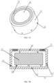
- FIGS. 4A and 4B are schematic structures of an exemplary bone conduction speaker.
- the bone conduction speaker may include a housing 10, a vibration board 21, and a transducer 22.
- the transducer 22 may be inside the housing 10 and configured to generate vibrations.
- the housing 10 may have one or more sound guiding holes 30.
- the sound guiding hole(s) 30 may be configured to guide sound waves inside the housing 10 to the outside of the housing 10.
- the guided sound waves may form interference with leaked sound waves generated by the vibrations of the housing 10, so as to reducing the amplitude of the leaked sound.
- the transducer 22 may be configured to convert an electrical signal to mechanical vibrations.
- the vibration board 21 may be connected to the transducer 22 and configured to vibrate along with the transducer 22.
- the vibration board 21 may stretch out from the opening of the housing 10, and touch the skin of the user and pass vibrations to auditory nerves through human tissues and bones, which in turn enables the user to hear sound.
- the linking component 23 may reside between the transducer 22 and the housing 10, configured to fix the vibrating transducer 122 inside the housing.
- the linking component 23 may include one or more separate components, or may be integrated with the transducer 22 or the housing 10. In some embodiments, the linking component 23 is made of an elastic material.
- side d is the outside surface of the bottom 12.
- S d is the region of side d
- P a , P b , P c and P e are functions of the position, when we set a hole on an arbitrary position in the housing, if the area of the hole is S hole , the sound pressure of the hole is ⁇ S hole Pds.
- FIG. 5 is a diagram illustrating the equal-loudness contour curves according to some embodiments of the present disclose.
- the horizontal coordinate is frequency
- the vertical coordinate is sound pressure level (SPL).
- SPL refers to the change of atmospheric pressure after being disturbed, i.e., a surplus pressure of the atmospheric pressure, which is equivalent to an atmospheric pressure added to a pressure change caused by the disturbance.
- the sound pressure may reflect the amplitude of a sound wave.
- sound pressure levels corresponding to different frequencies are different, while the loudness levels felt by human ears are the same.
- each curve is labeled with a number representing the loudness level of said curve.
- a plurality of sound guiding holes may be on the sidewall and/or the bottom of the housing.
- the sound guiding hole may be set on the upper portion and/or lower portion of the sidewall of the housing.
- the quantity of the sound guiding holes set on the sidewall of the housing is no less than two.
- the sound guiding holes may be arranged evenly or unevenly in one or more circles with respect to the center of the bottom.
- the sound guiding holes may be arranged in at least one circle.
- one sound guiding hole may be set on the bottom of the housing.
- the sound guiding hole may be set at the center of the bottom of the housing.
- the openings (and cross sections) of sound guiding holes may be circle, ellipse, rectangle, or slit.
- Slit generally means slit along with straight lines, curve lines, or arc lines.
- Different sound guiding holes in one bone conduction speaker may have same or different shapes.
- a damping layer is preferably set in a sound guiding hole 30 to adjust the phase and amplitude of the sound wave transmitted through the sound guiding hole 30.
- different portions of a sound guiding hole 30 may be configured to generate sound waves having a same phase to reduce the leaked sound waves with the same wavelength. In some embodiments, different portions of a sound guiding hole 30 may be configured to generate sound waves having different phases to reduce the leaked sound waves with different wavelengths.
- the transducer 22 is preferably implemented based on the principle of electromagnetic transduction.
- the transducer may include components such as magnetizer, voice coil, and etc., and the components may located inside the housing and may generate synchronous vibrations with a same frequency.
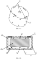
- FIGS. 9A and 9B are schematic structures of an exemplary bone conduction speaker according to some embodiments of the present disclosure.
- the bone conduction speaker may include an open housing 10, a vibration board 21 and a transducer 22.
- the housing 10 is cylindrical, with a sidewall and a bottom.
- One or more perforative sound guiding holes 30 may be along the circumference of the bottom.
- the shape of one or more of the sound guiding holes 30 may be rectangle.
- the effect of this scheme may cause a relatively balanced effect of reducing sound leakage in various frequency ranges compared to the schemes where the position of the holes are fixed.
- the effect of this design on reducing sound leakage is relatively better than that of other designs where the heights of the holes are fixed, such as embodiment three, embodiment four, embodiment five, etc.
- the sound guiding holes 30 in the above embodiments may be perforative holes without shields.
- different portions of a same sound guiding hole can be configured to generate a same phase to reduce leaked sound waves on the same wavelength (e.g. using a pre-set damping layer with the shape of stairs or steps). In some embodiments, different portions of a same sound guiding hole can be configured to generate different phases to reduce leaked sound waves on different wavelengths.
Landscapes
- Physics & Mathematics (AREA)
- Engineering & Computer Science (AREA)
- Acoustics & Sound (AREA)
- Signal Processing (AREA)
- Multimedia (AREA)
- Health & Medical Sciences (AREA)
- Otolaryngology (AREA)
- Electromagnetism (AREA)
- General Health & Medical Sciences (AREA)
- Neurosurgery (AREA)
- Details Of Audible-Bandwidth Transducers (AREA)
- Soundproofing, Sound Blocking, And Sound Damping (AREA)
Description
- This application relates to a bone conduction device, and more specifically, relates to methods and systems for reducing sound leakage by a bone conduction device.
- A bone conduction speaker, which may be also called a vibration speaker, may push human tissues and bones to stimulate the auditory nerve in cochlea and enable people to hear sound. The bone conduction speaker is also called a bone conduction headphone.
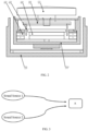
- An exemplary structure of a bone conduction speaker based on the principle of the bone conduction speaker is shown in
FIGs. 1A and 1B . The bone conduction speaker may include anopen housing 110, avibration board 121, atransducer 122, and a linkingcomponent 123. Thetransducer 122 may transduce electrical signals to mechanical vibrations. Thevibration board 121 may be connected to thetransducer 122 and vibrate synchronically with thetransducer 122. Thevibration board 121 may stretch out from the opening of thehousing 110 and contact with human skin to pass vibrations to auditory nerves through human tissues and bones, which in turn enables people to hear sound. The linkingcomponent 123 may reside between thetransducer 122 and thehousing 110, configured to fix the vibratingtransducer 122 inside thehousing 110. To minimize its effect on the vibrations generated by thetransducer 122, the linkingcomponent 123 may be made of an elastic material. - However, the mechanical vibrations generated by the
transducer 122 may not only cause thevibration board 121 to vibrate, but may also cause thehousing 110 to vibrate through the linkingcomponent 123. Accordingly, the mechanical vibrations generated by the bone conduction speaker may push human tissues through thebone board 121, and at the same time a portion of the vibratingboard 121 and thehousing 110 that are not in contact with human issues may nevertheless push air. Air sound may thus be generated by the air pushed by the portion of the vibratingboard 121 and thehousing 110. The air sound may be called "sound leakage." In some cases, sound leakage is harmless. However, sound leakage should be avoided as much as possible if people intend to protect privacy when using the bone conduction speaker or try not to disturb others when listening to music. - Attempting to solve the problem of sound leakage, Korean patent
KR10-2009-0082999 FIG. 2 , the speaker disclosed in the patent includes: afirst frame 210 with an open upper portion and asecond frame 220 that surrounds the outside of thefirst frame 210. Thesecond frame 220 is separately placed from the outside of thefirst frame 210. Thefirst frame 210 includes amovable coil 230 with electric signals, an innermagnetic component 240, an outermagnetic component 250, a magnet field formed between the innermagnetic component 240, and the outermagnetic component 250. The innermagnetic component 240 and the outmagnetic component 250 may vibrate by the attraction and repulsion force of thecoil 230 placed in the magnet field. Avibration board 260 connected to the movingcoil 230 may receive the vibration of the movingcoil 230. Avibration unit 270 connected to the vibration board 260may pass the vibration to a user by contacting with the skin. As described in the patent, thesecond frame 220 surrounds thefirst frame 210, in order to use thesecond frame 220 to prevent the vibration of thefirst frame 210 from dissipating the vibration to outsides, and thus may reduce sound leakage to some extent. - However, in this design, since the
second frame 220 is fixed to thefirst frame 210, vibrations of thesecond frame 220 are inevitable. As a result, sealing by thesecond frame 220 is unsatisfactory. Furthermore, thesecond frame 220 increases the whole volume and weight of the speaker, which in turn increases the cost, complicates the assembly process, and reduces the speaker's reliability and consistency. -
WO2013/047609A1 relates to a cellular phone (portable electronic apparatus) that transmits sound to a user by means of vibration sound. The cellular phone is provided with housings and a piezoelectric element, and vibrates, by means of the piezoelectric element, a cellular phone portion in contact with the user, transmits the vibration to the user, and makes the user hear the vibration sound. -
JP2007251358A -
CN103167390A relates to a kind of osteoacusis receiver, particularly a kind of osteoacusis receiver with conductance effect. -
US6850138B1 relates to a vibration actuator which is mainly mounted on mobile communication apparatuses such as a cellular phone, and which has a function of generating a call sound, a voice, and a vibration. - The invention provides a method and system of reducing sound leakage of a bone conduction speaker.
- In one aspect, the invention provides a method of reducing sound leakage of a bone conduction speaker according to
claim 1. The method includes: - providing a bone conduction speaker including a vibration board fitting human skin and passing vibrations, a transducer, and a housing, wherein at least one sound guiding hole is located in at least one portion of the housing;
- the transducer drives the vibration board to vibrate;
- the housing vibrates, along with the vibrations of the transducer, and pushes air, forming a leaked sound wave transmitted in the air;
- the air inside the housing is pushed out of the housing through the at least one sound guiding hole, interferes with the leaked sound wave, and reduces an amplitude of the leaked sound wave.
- In some embodiments, one or more sound guiding holes may locate in an upper portion, a central portion, and/or a lower portion of a sidewall and/or the bottom of the housing.
- In some embodiments, a damping layer may be applied in the at least one sound guiding hole in order to adjust the phase and amplitude of the guided sound wave through the at least one sound guiding hole.
- In some embodiments, sound guiding holes may be configured to generate guided sound waves having a same phase that reduce the leaked sound wave having a same wavelength; sound guiding holes may be configured to generate guided sound waves having different phases that reduce the leaked sound waves having different wavelengths.
- In some embodiments, different portions of a same sound guiding hole may be configured to generate guided sound waves having a same phase that reduce the leaked sound wave having same wavelength. In some embodiments, different portions of a same sound guiding hole may be configured to generate guided sound waves having different phases that reduce leaked sound waves having different wavelengths.
- In another aspect, the invention provides a bone conduction speaker according to
claim 2. The bone conduction speaker includes a housing, a vibration board and a transducer, wherein: - the transducer is configured to generate vibrations and is located inside the housing;
- the vibration board is configured to be in contact with skin and pass vibrations;
- At least one sound guiding hole is located in at least one portion on the housing, and the at least one sound guiding hole is configured to guide a sound wave inside the housing, resulted from vibrations of the air inside the housing, to the outside of the housing, the guided sound wave interfering with the leaked sound wave and reducing the amplitude thereof.
- According to the invention, the at least one sound guiding hole is located in the sidewall and/or bottom of the housing.
- In some embodiments, preferably, the at least one sound guiding sound hole may locate in the upper portion and/or lower portion of the sidewall of the housing.
- In some embodiments, preferably, the sidewall of the housing is cylindrical and there are at least two sound guiding holes located in the sidewall of the housing, which are arranged evenly or unevenly in one or more circles. Alternatively, the housing may have a different shape.
- In some embodiments, preferably, the sound guiding holes have different heights along the axial direction of the cylindrical sidewall.
- In some embodiments, preferably, there are at least two sound guiding holes located in the bottom of the housing. In some embodiments, the sound guiding holes are distributed evenly or unevenly in one or more circles around the center of the bottom. Alternatively or additionally, one sound guiding hole is located at the center of the bottom of the housing.
- In some embodiments, preferably, the sound guiding hole is a perforative hole. In some embodiments, there may be a damping layer at the opening of the sound guiding hole.
- In some embodiments, preferably, the guided sound waves through different sound guiding holes and/or different portions of a same sound guiding hole have different phases or a same phase.
- In some embodiments, preferably, the damping layer is a tuning paper, a tuning cotton, a nonwoven fabric, a silk, a cotton, a sponge, or a rubber.
- In some embodiments, preferably, the shape of a sound guiding hole is circle, ellipse, quadrangle, rectangle, or linear. In some embodiments, the sound guiding holes may have a same shape or different shapes.
- In some embodiments, preferably, the transducer includes a magnetic component and a voice coil. Alternatively, the transducer includes piezoelectric ceramic.
- The design disclosed in this application utilizes the principles of sound interference, by placing sound guiding holes in the housing, to guide sound wave(s) inside the housing to the outside of the housing, the guided sound wave(s) interfering with the leaked sound wave, which is formed when the housing's vibrations push the air outside the housing. The guided sound wave(s) reduces the amplitude of the leaked sound wave and thus reduces the sound leakage. The design not only reduces sound leakage, but is also easy to implement, doesn't increase the volume or weight of the bone conduction speaker, and barely increase the cost of the product.
-
-
FIGs. 1A and 1B are schematic structures illustrating a bone conduction speaker of prior art; -
FIG. 2 is a schematic structure illustrating another bone conduction speaker of prior art; -
FIG. 3 illustrates the principle of sound interference according to some embodiments of the present disclosure; -
FIGs. 4A and 4B are schematic structures of an exemplary bone conduction speaker according to some embodiments of the present disclosure; -
FIG. 4C is a schematic structure of the bone conduction speaker according to some embodiments of the present disclosure; -
FIG. 4D is a diagram illustrating reduced sound leakage of the bone conduction speaker according to some embodiments of the present disclosure; -
FIG. 5 is a diagram illustrating the equal-loudness contour curves according to some embodiments of the present disclosure; -
FIG. 6 is a flow chart of an exemplary method of reducing sound leakage of a bone conduction speaker according to some embodiments of the present disclosure; -
FIGs. 7A and 7B are schematic structures of an exemplary bone conduction speaker according to some embodiments of the present disclosure; -
FIG. 7C is a diagram illustrating reduced sound leakage of a bone conduction speaker according to some embodiments of the present disclosure; -
FIGs. 8A and8B are schematic structure of an exemplary bone conduction speaker according to some embodiments of the present disclosure; -
FIG. 8C is a diagram illustrating reduced sound leakage of a bone conduction speaker according to some embodiments of the present disclosure; -
FIGs. 9A and 9B are schematic structures of an exemplary bone conduction speaker according to some embodiments of the present disclosure; -
FIG. 9C is a diagram illustrating reduced sound leakage of a bone conduction speaker according to some embodiments of the present disclosure; -
FIGS. 10A and10B are schematic structures of an exemplary bone conduction speaker according to some embodiments of the present disclosure; -
FIG. 10C is a diagram illustrating reduced sound leakage of a bone conduction speaker according to some embodiments of the present disclosure; -
FIGs. 11A and 11B are schematic structures of an exemplary bone conduction speaker according to some embodiments of the present disclosure; -
FIG. 11C is a diagram illustrating reduced sound leakage of a bone conduction speaker according to some embodiments of the present disclosure; and -
FIGs. 12A and12B are schematic structures of an exemplary bone conduction speaker according to some embodiments of the present disclosure; -
FIGs. 13A and13B are schematic structures of an exemplary bone conduction speaker according to some embodiments of the present disclosure. - The meanings of the mark numbers in the figures are as followed:
110, open housing; 121, vibration board; 122, transducer; 123, linking component; 210, first frame; 220, second frame; 230, moving coil; 240, inner magnetic component; 250, outer magnetic component; 260; vibration board; 270, vibration unit; 10, housing; 11, sidewall; 12, bottom; 21, vibration board; 22, transducer; 23, linking component; 24, elastic component; 30, sound guiding hole. - Followings are some further detailed illustrations about this disclosure. The following examples are for illustrative purposes only and should not be interpreted as limitations of the claimed invention. There are a variety of alternative techniques and procedures available to those of ordinary skill in the art, which would similarly permit one to successfully perform the intended invention. In addition, the figures just show the structures relative to this disclosure, not the whole structure.
- To explain the scheme of the embodiments of this disclosure, the design principles of this disclosure will be introduced here.
FIG. 3 illustrates the principles of sound interference according to some embodiments of the present disclosure. Two or more sound waves may interfere in the space based on, for example, the frequency and/or amplitude of the waves. Specifically, the amplitudes of the sound waves with the same frequency may be overlaid to generate a strengthened wave or a weakened wave. As shown inFIG. 3 , soundsource 1 and soundsource 2 have the same frequency and locate in different locations in the space. The sound waves generated from these two sound sources may encounter in an arbitrary point A. If the phases of thesound wave 1 andsound wave 2 are the same at point A, the amplitudes of the two sound waves may be added, generating a strengthened sound wave signal at point A; on the other hand, if the phases of the two sound waves are opposite at point A, their amplitudes may be offset, generating a weakened sound wave signal at point A. - This disclosure applies above-noted the principles of sound wave interference to a bone conduction speaker and disclose a bone conduction speaker that can reduce sound leakage.
-
FIGS. 4A and 4B are schematic structures of an exemplary bone conduction speaker. The bone conduction speaker may include ahousing 10, avibration board 21, and atransducer 22. Thetransducer 22 may be inside thehousing 10 and configured to generate vibrations. Thehousing 10 may have one or more sound guiding holes 30. The sound guiding hole(s) 30 may be configured to guide sound waves inside thehousing 10 to the outside of thehousing 10. In some embodiments, the guided sound waves may form interference with leaked sound waves generated by the vibrations of thehousing 10, so as to reducing the amplitude of the leaked sound. Thetransducer 22 may be configured to convert an electrical signal to mechanical vibrations. For example, an audio electrical signal may be transmitted into a voice coil that is placed in a magnet, and the electromagnetic interaction may cause the voice coil to vibrate based on the audio electrical signal. As another example, thetransducer 22 may include piezoelectric ceramics, shape changes of which may cause vibrations in accordance with electrical signals received. - Furthermore, the
vibration board 21 may be connected to thetransducer 22 and configured to vibrate along with thetransducer 22. Thevibration board 21 may stretch out from the opening of thehousing 10, and touch the skin of the user and pass vibrations to auditory nerves through human tissues and bones, which in turn enables the user to hear sound. The linkingcomponent 23 may reside between thetransducer 22 and thehousing 10, configured to fix the vibratingtransducer 122 inside the housing. The linkingcomponent 23 may include one or more separate components, or may be integrated with thetransducer 22 or thehousing 10. In some embodiments, the linkingcomponent 23 is made of an elastic material. - The
transducer 22 may drive thevibration board 21 to vibrate. Thetransducer 22, which resides inside thehousing 10, may vibrate. The vibrations of thetransducer 22 may drives the air inside thehousing 10 to vibrate, producing a sound wave inside thehousing 10, which can be referred to as "sound wave inside the housing." Since thevibration board 21 and thetransducer 22 are fixed to thehousing 10 via the linkingcomponent 23, the vibrations may pass to thehousing 10, causing thehousing 10 to vibrate synchronously. The vibrations of thehousing 10 may generate a leaked sound wave, which spreads outwards as sound leakage. - The sound wave inside the housing and the leaked sound wave are like the two sound sources in
FIG. 3 . In some embodiments, thesidewall 11 of thehousing 10 may have one or moresound guiding holes 30 configured to guide the sound wave inside thehousing 10 to the outside. The guided sound wave through the sound guiding hole(s) 30 may interfere with the leaked sound wave generated by the vibrations of thehousing 10, and the amplitude of the leaked sound wave may be reduced due to the interference, which may result in a reduced sound leakage. Therefore, the design of this embodiment can solve the sound leakage problem to some extent by making an improvement of setting a sound guiding hole on the housing, and not increasing the volume and weight of the bone conduction speaker. - In some embodiments, one
sound guiding hole 30 is set on the upper portion of thesidewall 11. As used herein, the upper portion of thesidewall 11 refers to the portion of thesidewall 11 starting from the top of the sidewall (contacting with the vibration board 21) to about the 1/3 height of the sidewall. -
FIG. 4C is a schematic structure of the bone conduction speaker illustrated inFIGs. 4A-4B . The structure of the bone conduction speaker is further illustrated with mechanics elements illustrated inFIG. 4C . As shown inFIG. 4C , the linkingcomponent 23 between thesidewall 11 of thehousing 10 and thevibration board 21 may be represented by anelastic element 23 and a damping element in the parallel connection. The linking relationship between thevibration board 21 and thetransducer 22 may be represented by anelastic element 24. - Outside the
housing 10, the sound leakage reduction is proportional to
sound guiding hole 30, Shousing is the area of the housing 10 (e.g., thesidewall 11 and the bottom 12) that is not in contact with human face. - The pressure inside the housing may be expressed as

- The center of the side b, O point, is set as the origin of the space coordinates, and the side b can be set as the z=0 plane, so Pa, Pb, Pc and Pe may be expressed as follows:


- wherein

-


-


-


- k= ω/u(u is the velocity of sound) is wave number, ρ 0 is an air density, ω is an angular frequency of vibration;
- PaR, PbR, PcR and PeR are acoustic resistances of air, which respectively are:


- Wa(x,y), Wb(x,y), Wc(x,y), We(x,y) and Wd(x,y) are the sound source power per unit area of side a, side b, side c, side e and side d, respectively, which can be derived from following formulas (11):

housing 10 and thetransducer 22, f = ηΔs(dv/dy), - L is the equivalent load on human face when the vibration board acts on a human face, γ is the energy dissipated on
elastic element 24, k1 and k2 are the elastic coefficients ofelastic element 1 andelastic element 2 respectively, η is the fluid viscosity coefficient, dv/dy is the velocity gradient of fluid, Δs is the cross-section area of a subject (board), A is the amplitude, ϕ is the region of the sound field, δ is a high order minimum (which is generated by the incompletely symmetrical shape of the housing); - The sound pressure of an arbitrary point outside the housing, generated by the vibration of the
housing 10 is expressed as:


- Pa, Pb, Pc and Pe are functions of the position, when we set a hole on an arbitrary position in the housing, if the area of the hole is Shole, the sound pressure of the hole is ∫∫S
hole Pds. - In the meanwhile, because the
vibration board 21 fits human tissues tightly, the power it gives out is absorbed all by human tissues, so the only side that can push air outside the housing to vibrate is side d, thus forming sound leakage. As described elsewhere, the sound leakage is resulted from the vibrations of thehousing 10. For illustrative purposes, the sound pressure generated by thehousing 10 may be expressed as ∫∫S housing Pd ds. - The leaked sound wave and the guided sound wave interference may result in a weakened sound wave, i.e., to make ∫∫S
hole Pds and ∫∫S housing Pd ds have the same value but opposite directions, and the sound leakage may be reduced. In some embodiments, ∫∫Shole Pds may be adjusted to reduce the sound leakage. Since ∫∫Shole Pds corresponds to information of phases and amplitudes of one or more holes, which further relates to dimensions of the housing of the bone conduction speaker, the vibration frequency of the transducer, the position, shape, quantity and/or size of the sound guiding holes and whether there is damping inside the holes. Thus, the position, shape, and quantity of sound guiding holes, and/or damping materials may be adjusted to reduce sound leakage. - Additionally, because of the basic structure and function differences of a bone conduction speaker and a traditional air conduction speaker, the formulas above are only suitable for bone conduction speakers. Whereas in traditional air conduction speakers, the air in the air housing can be treated as a whole, which is not sensitive to positions, and this is different intrinsically with a bone conduction speaker, therefore the above formulas are not suitable to an air conduction speaker.
- According to the formulas above, a person having ordinary skill in the art would understand that the effectiveness of reducing sound leakage is related to the dimensions of the housing of the bone conduction speaker, the vibration frequency of the transducer, the position, shape, quantity and size of the sound guiding hole(s) and whether there is damping inside the sound guiding hole(s). Accordingly, various configurations, depending on specific needs, may be obtained by choosing specific position where the sound guiding hole(s) is located, the shape and/or quantity of the sound guiding hole(s) as well as the damping material.
-
FIG. 5 is a diagram illustrating the equal-loudness contour curves according to some embodiments of the present disclose. The horizontal coordinate is frequency, while the vertical coordinate is sound pressure level (SPL). As used herein, the SPL refers to the change of atmospheric pressure after being disturbed, i.e., a surplus pressure of the atmospheric pressure, which is equivalent to an atmospheric pressure added to a pressure change caused by the disturbance. As a result, the sound pressure may reflect the amplitude of a sound wave. InFIG. 5 , on each curve, sound pressure levels corresponding to different frequencies are different, while the loudness levels felt by human ears are the same. For example, each curve is labeled with a number representing the loudness level of said curve. According to the loudness level curves, when volume (sound pressure amplitude) is lower, human ears are not sensitive to sounds of high or low frequencies; when volume is higher, human ears are more sensitive to sounds of high or low frequencies. Bone conduction speakers may generate sound relating to different frequency ranges, such as 1000Hz~4000Hz, or1000Hz~4000Hz, or 1000Hz~3500Hz, or 1000Hz~3000Hz, or 1500Hz~3000Hz. The sound leakage within the above-mentioned frequency ranges may be the sound leakage aimed to be reduced with a priority. -
FIG. 4D is a diagram illustrating the effect of reduced sound leakage according to some embodiments of the present disclosure, wherein the test results and calculation results are close in the above range. The bone conduction speaker being tested includes a cylindrical housing, which includes a sidewall and a bottom, as described inFIGs. 4A and 4B . The cylindrical housing is in a cylinder shape having a radius of 22mm, the sidewall height of 14mm, and a plurality of sound guiding holes being set on the upper portion of the sidewall of the housing. The openings of the sound guiding holes are rectangle. The sound guiding holes are arranged evenly on the sidewall. The target region where the sound leakage is to be reduced is 50cm away from the outside of the bottom of the housing. The distance of the leaked sound wave spreading to the target region and the distance of the sound wave spreading from the surface of thetransducer 20 through thesound guiding holes 20 to the target region have a difference of about 180 degrees in phase. As shown, the leaked sound wave is reduced in the target region dramatically or even be eliminated. - According to the embodiments in this disclosure, the effectiveness of reducing sound leakage after setting sound guiding holes is very obvious. As shown in
FIG. 4D , the bone conduction speaker having sound guiding holes greatly reduce the sound leakage compared to the bone conduction speaker without sound guiding holes. - In the tested frequency range, after setting sound guiding holes, the sound leakage is reduced by about 10dB on average. Specifically, in the frequency range of 1500Hz~3000Hz, the sound leakage is reduced by over 10dB. In the frequency range of 2000Hz~2500Hz, the sound leakage is reduced by over 20dB compared to the scheme without sound guiding holes.
- A person having ordinary skill in the art can understand from the above-mentioned formulas that when the dimensions of the bone conduction speaker, target regions to reduce sound leakage and frequencies of sound waves differ, the position, shape and quantity of sound guiding holes also need to adjust accordingly.
- For example, in a cylinder housing, according to different needs, a plurality of sound guiding holes may be on the sidewall and/or the bottom of the housing. Preferably, the sound guiding hole may be set on the upper portion and/or lower portion of the sidewall of the housing. The quantity of the sound guiding holes set on the sidewall of the housing is no less than two. Preferably, the sound guiding holes may be arranged evenly or unevenly in one or more circles with respect to the center of the bottom. In some embodiments, the sound guiding holes may be arranged in at least one circle. In some embodiments, one sound guiding hole may be set on the bottom of the housing. In some embodiments, the sound guiding hole may be set at the center of the bottom of the housing.
- The quantity of the sound guiding holes can be one or more. Preferably, multiple sound guiding holes may be set symmetrically on the housing. In some embodiments, there are 6-8 circularly arranged sound guiding holes.
- The openings (and cross sections) of sound guiding holes may be circle, ellipse, rectangle, or slit. Slit generally means slit along with straight lines, curve lines, or arc lines. Different sound guiding holes in one bone conduction speaker may have same or different shapes.
- A person having ordinary skill in the art can understand that, the sidewall of the housing may not be cylindrical, the sound guiding holes can be arranged asymmetrically as needed. Various configurations may be obtained by setting different combinations of the shape, quantity, and position of the sound guiding. Some other embodiments along with the figures are described as follows.
-
FIG. 6 is a flowchart of an exemplary method of reducing sound leakage of a bone conduction speaker according to some embodiments of the present disclosure. At 601, a bone conduction speaker including avibration plate 21 touching human skin and passing vibrations, atransducer 22, and ahousing 10 is provided. At least onesound guiding hole 30 is arranged on thehousing 10. At 602, thevibration plate 21 is driven by thetransducer 22, causing thevibration 21 to vibrate. At 603, a leaked sound wave due to the vibrations of the housing is formed, wherein the leaked sound wave transmits in the air. At 604, a guided sound wave passing through the at least onesound guiding hole 30 from the inside to the outside of thehousing 10. The guided sound wave interferes with the leaked sound wave, reducing the sound leakage of the bone conduction speaker. - The
sound guiding holes 30 are preferably set at different positions of thehousing 10. - The effectiveness of reducing sound leakage may be determined by the formulas and method as described above, based on which the positions of sound guiding holes may be determined.
- A damping layer is preferably set in a
sound guiding hole 30 to adjust the phase and amplitude of the sound wave transmitted through thesound guiding hole 30. - In some embodiments, different sound guiding holes may generate different sound waves having a same phase to reduce the leaked sound wave having the same wavelength. In some embodiments, different sound guiding holes may generate different sound waves having different phases to reduce the leaked sound waves having different wavelengths.
- In some embodiments, different portions of a
sound guiding hole 30 may be configured to generate sound waves having a same phase to reduce the leaked sound waves with the same wavelength. In some embodiments, different portions of asound guiding hole 30 may be configured to generate sound waves having different phases to reduce the leaked sound waves with different wavelengths. - Additionally, the sound wave inside the housing may be processed to basically have the same value but opposite phases with the leaked sound wave, so that the sound leakage may be further reduced.
-
FIGS. 7A and 7B are schematic structures illustrating an exemplary bone conduction speaker according to some embodiments of the present disclosure. The bone conduction speaker may include anopen housing 10, avibration board 21, and atransducer 22. Thehousing 10 may cylindrical and have a sidewall and a bottom. A plurality ofsound guiding holes 30 may be arranged on the lower portion of the sidewall (i.e., from about the 2/3 height of the sidewall to the bottom). The quantity of thesound guiding holes 30 may be 8, the openings of thesound guiding holes 30 may be rectangle. Thesound guiding holes 30 may be arranged evenly or evenly in one or more circles on the sidewall of thehousing 10. - In the embodiment, the
transducer 22 is preferably implemented based on the principle of electromagnetic transduction. The transducer may include components such as magnetizer, voice coil, and etc., and the components may located inside the housing and may generate synchronous vibrations with a same frequency. -
FIG. 7C is a diagram illustrating reduced sound leakage according to some embodiments of the present disclosure. In the frequency range of 1400Hz~4000Hz, the sound leakage is reduced by more than 5dB, and in the frequency range of 2250Hz~2500Hz, the sound leakage is reduced by more than 20dB. -
FIGS. 8A and8B are schematic structures illustrating an exemplary bone conduction speaker according to some embodiments of the present disclosure. The bone conduction speaker may include anopen housing 10, avibration board 21, and atransducer 22. Thehousing 10 is cylindrical and have a sidewall and a bottom. Thesound guiding holes 30 may be arranged on the central portion of the sidewall of the housing (i.e., from about the 1/3 height of the sidewall to the 2/3 height of the sidewall). The quantity of thesound guiding holes 30 may be 8, and the openings (and cross sections) of thesound guiding hole 30 may be rectangle. Thesound guiding holes 30 may be arranged evenly or unevenly in one or more circles on the sidewall of thehousing 10. - In the embodiment, the
transducer 21 may be implemented preferably based on the principle of electromagnetic transduction. Thetransducer 21 may include components such as magnetizer, voice coil, etc., which may be placed inside the housing and may generate synchronous vibrations with the same frequency. -
FIG. 8C is a diagram illustrating reduced sound leakage. In the frequency range of 1000Hz~4000Hz, the effectiveness of reducing sound leakage is great. For example, in the frequency range of 1400Hz~2900Hz, the sound leakage is reduced by more than 10dB; in the frequency range of 2200Hz~2500Hz, the sound leakage is reduced by more than 20dB. - It's illustrated that the effectiveness of reduced sound leakage can be adjusted by changing the positions of the sound guiding holes, while keeping other parameters relating to the sound guiding holes unchanged.
-
FIGS. 9A and 9B are schematic structures of an exemplary bone conduction speaker according to some embodiments of the present disclosure. The bone conduction speaker may include anopen housing 10, avibration board 21 and a transducer 22.Thehousing 10 is cylindrical, with a sidewall and a bottom. One or more perforativesound guiding holes 30 may be along the circumference of the bottom. In some embodiments, there may be 8sound guiding holes 30 arranged evenly of unevenly in one or more circles on the bottom of thehousing 10. In some embodiments, the shape of one or more of thesound guiding holes 30 may be rectangle. - In the embodiment, the
transducer 21 may be implemented preferably based on the principle of electromagnetic transduction. Thetransducer 21 may include components such as magnetizer, voice coil, etc., which may be placed inside the housing and may generate synchronous vibration with the same frequency. -
FIG. 9C is a diagram illustrating the effect of reduced sound leakage. In the frequency range of 1000Hz~3000Hz, the effectiveness of reducing sound leakage is outstanding. For example, in the frequency range of 1700Hz~2700Hz, the sound leakage is reduced by more than 10dB; in the frequency range of 2200Hz~2400Hz, the sound leakage is reduced by more than 20dB. -
FIGS. 10A and10B are schematic structures of an exemplary bone conduction speaker according to some embodiments of the present disclosure. The bone conduction speaker may include anopen housing 10, avibration board 21 and atransducer 22. One or more perforativesound guiding holes 30 may be arranged on both upper and lower portions of the sidewall of thehousing 10. Thesound guiding holes 30 may be arranged evenly or unevenly in one or more circles on the upper and lower portions of the sidewall of thehousing 10. In some embodiments, the quantity ofsound guiding holes 30 in every circle may be 8, and the upper portion sound guiding holes and the lower portion sound guiding holes may be symmetrical about the central cross section of thehousing 10. In some embodiments, the shape of thesound guiding hole 30 may be circle. - The shape of the sound guiding holes on the upper portion and the shape of the sound guiding holes on the lower portion may be different; One or more damping layers may be arranged in the sound guiding holes to reduce leaked sound waves of the same wave length (or frequency), or to reduce leaked sound waves of different wave lengths.
-
FIG. 10C is a diagram illustrating the effect of reducing sound leakage according to some embodiments of the present disclosure. In the frequency range of 1000Hz~4000Hz, the effectiveness of reducing sound leakage is outstanding. For example, in the frequency range of 1600Hz~2700Hz, the sound leakage is reduced by more than 15dB; in the frequency range of 2000Hz~2500Hz, where the effectiveness of reducing sound leakage is most outstanding, the sound leakage is reduced by more than 20dB. Compared to embodiment three, this scheme has a relatively balanced effect of reduced sound leakage on various frequency range, and this effect is better than the effect of schemes where the height of the holes are fixed, such as schemes of embodiment three, embodiment four, embodiment five, and so on. -
FIGS. 11A and 11B are schematic structures illustrating a bone conduction speaker according to some embodiments of the present disclosure. The bone conduction speaker may include anopen housing 10, avibration board 21 and atransducer 22. One or more perforativesound guiding holes 30 may be set on upper and lower portions of the sidewall of thehousing 10 and on the bottom of thehousing 10. Thesound guiding holes 30 on the sidewall are arranged evenly or unevenly in one or more circles on the upper and lower portions of the sidewall of thehousing 10. In some embodiments, the quantity ofsound guiding holes 30 in every circle may be 8, and the upper portion sound guiding holes and the lower portion sound guiding holes may be symmetrical about the central cross section of thehousing 10. In some embodiments, the shape of thesound guiding hole 30 may be rectangular. There may be four sound guiding holds 30 on the bottom of thehousing 10. The foursound guiding holes 30 may be linear-shaped along arcs, and may be arranged evenly or unevenly in one or more circles with respect to the center of the bottom. Furthermore, thesound guiding holes 30 may include a circular perforative hole on the center of the bottom. -
FIG. 11C is a diagram illustrating the effect of reducing sound leakage of the embodiment. In the frequency range of 1000Hz~4000Hz, the effectiveness of reducing sound leakage is outstanding. For example, in the frequency range of 1300Hz~3000Hz, the sound leakage is reduced by more than 10dB; in the frequency range of 2000Hz~2700Hz, the sound leakage is reduced by more than 20dB. Compared to embodiment three, this scheme has a relatively balanced effect of reduced sound leakage within various frequency range, and this effect is better than the effect of schemes where the height of the holes are fixed, such as schemes of embodiment three, embodiment four, embodiment five, and etc. Compared to embodiment six, in the frequency range of 1000Hz~1700Hz and 2500Hz~4000Hz, this scheme has a better effect of reduced sound leakage than embodiment six. -
FIGS. 12A and12B are schematic structures illustrating a bone conduction speaker according to some embodiments of the present disclosure. The bone conduction speaker may include anopen housing 10, avibration board 21 and atransducer 22. A perforativesound guiding hole 30 may be set on the upper portion of the sidewall of thehousing 10. One or more sound guiding holes may be arranged evenly or unevenly in one or more circles on the upper portion of the sidewall of thehousing 10. There may be 8sound guiding holes 30, and the shape of thesound guiding holes 30 may be circle. - After comparison of calculation results and test results, the effectiveness of this embodiment is basically the same with that of embodiment one, and this embodiment can effectively reduce sound leakage.
-
FIGS. 13A and13B are schematic structures illustrating a bone conduction speaker according to some embodiments of the present disclosure. The bone conduction speaker may include anopen housing 10, avibration board 21 and atransducer 22. - The difference between this embodiment and the above-described embodiment three is that to reduce sound leakage to greater extent, the
sound guiding holes 30 may be arranged on the upper, central and lower portions of thesidewall 11. Thesound guiding holes 30 are arranged evenly or unevenly in one or more circles. Different circles are formed by thesound guiding holes 30, one of which is set along the circumference of the bottom 12 of thehousing 10. The size of thesound guiding holes 30 are the same. - The effect of this scheme may cause a relatively balanced effect of reducing sound leakage in various frequency ranges compared to the schemes where the position of the holes are fixed. The effect of this design on reducing sound leakage is relatively better than that of other designs where the heights of the holes are fixed, such as embodiment three, embodiment four, embodiment five, etc.
- The
sound guiding holes 30 in the above embodiments may be perforative holes without shields. - In order to adjust the effect of the sound waves guided from the sound guiding holes, a damping layer (not shown in the figures) may locate at the opening of a
sound guiding hole 30 to adjust the phase and/or the amplitude of the sound wave. - There are multiple variations of materials and positions of the damping layer. For example, the damping layer may be made of materials which can damp sound waves, such as tuning paper, tuning cotton, nonwoven fabric, silk, cotton, sponge or rubber. The damping layer may be attached on the inner wall of the
sound guiding hole 30, or may shield thesound guiding hole 30 from outside. - More preferably, the damping layers corresponding to different
sound guiding holes 30 may be arranged to adjust the sound waves from different sound guiding holes to generate a same phase. The adjusted sound waves may be used to reduce leaked sound wave having the same wavelength. Alternatively, differentsound guiding holes 30 may be arranged to generate different phases to reduce leaked sound wave having different wavelengths (i.e. leaked sound waves with specific wavelengths). - In some embodiments,, different portions of a same sound guiding hole can be configured to generate a same phase to reduce leaked sound waves on the same wavelength (e.g. using a pre-set damping layer with the shape of stairs or steps). In some embodiments, different portions of a same sound guiding hole can be configured to generate different phases to reduce leaked sound waves on different wavelengths.
- The above-described embodiments are preferable embodiments with various configurations of the sound guiding hole(s) on the housing of a bone conduction speaker, but a person having ordinary skills in the art can understand that the embodiments don't limit the configurations of the sound guiding hole(s) to those described in this application.
- In the past bone conduction speakers, the housing of the bone conduction speakers is closed, so the sound source inside the housing is sealed inside the housing. In the embodiments of the present disclosure, there can be holes in proper positions of the housing, making the sound waves inside the housing and the leaked sound waves having substantially same amplitude and substantially opposite phases in the space, so that the sound waves can interfere with each other and the sound leakage of the bone conduction speaker is reduced. Meanwhile, the volume and weight of the speaker do not increase, the reliability of the product is not comprised, and the cost is barely increased. The designs disclosed herein are easy to implement, reliable, and effective in reducing sound leakage.
- It's noticeable that above statements are preferable embodiments and technical principles thereof. A person having ordinary skill in the art is easy to understand that this disclosure is not limited to the specific embodiments stated, and a person having ordinary skill in the art can make various obvious variations, adjustments, and substitutes within the protected scope of this disclosure. Therefore, although above embodiments state this disclosure in detail, this disclosure is not limited to the embodiments, and there can be many other equivalent embodiments within the scope of the present disclosure, and the protected scope of this disclosure is determined by following claims.
Claims (12)
- A method of reducing sound leakage, the method comprising:
providing a bone conduction speaker including:a vibration board (21);a transducer (22) configured to cause the vibration board to vibrate;a housing (10),the vibration board (21) touching human skin, and passing vibration to auditory nerves through human tissues and bones, andthe transducer (22) causing the housing (10) to vibrate, the vibration of the housing (10) producing a leaked sound wave; andat least one sound guiding hole (30) located on the housing (10) and configured to guide a sound wave inside the housing (10) through the at least one sound guiding hole (30) to an outside of the housing (10), wherein the guided sound wave interferes with the leaked sound wave, the interference reducing an amplitude of at least a portion of the leaked sound wave, a frequency of the at least a portion of the leaked sound wave being lower than 4000 Hz,wherein the housing (10) includes a sidewall (11) and a bottom (12) that are not in contact with human skin; and the at least one sound guiding hole (30) is located on the sidewall (11) or the bottom (12). - A bone conduction speaker comprising:a vibration board (21);a transducer (22) configured to cause the vibration board to vibrate;a housing (10),the vibration board (21) being arranged such that, in an operating position of the bone conduction speaker, the vibration board touches human skin and passes vibration to auditory nerves through human tissues and bones, andthe transducer (22) causing the housing (10) to vibrate, the vibration of the housing (10) producing a leaked sound wave; andat least one sound guiding hole (30) located on the housing (10) and configured to guide a sound wave inside the housing (10) through the at least one sound guiding hole (30) to an outside of the housing (10), wherein the at least one sound guiding hole (30) is configured to guide said sound wave such that the guided sound wave interferes with the leaked sound wave, the interference reducing an amplitude of at least a portion of the leaked sound wave, a frequency of the at least a portion of the leaked sound wave being lower than 4000 Hz,wherein the housing (10) includes a sidewall (11) and a bottom (12) arranged such that, in the operating position of the bone conduction speaker, the sidewall (11) and the bottom (12) are not in contact with the human skin; and the at least one sound guiding hole (30) is located on the sidewall (11) or the bottom (12).
- The bone conduction speaker of claim 2, wherein the at least one sound guiding hole (30) includes two sound guiding holes.
- The bone conduction speaker of claim 2, wherein the housing (10) includes a cylindrical sidewall, the at least one sound guiding hole (30) including at least two sound guiding holes, the at least two sound guiding holes located on the cylindrical sidewall.
- The bone conduction speaker of claim 4, wherein the two sound guiding holes locate at different heights along an axial direction of the sidewall (11).
- The bone conduction speaker of claim 2, wherein the guided sound wave includes at least two sound waves generated by different sound guiding holes, the at least two sound waves having a same phase, the at least two sound waves configured to reduce an amplitude of the leaked sound wave having same wavelength.
- The bone conduction speaker of claim 2, wherein the at least one sound guiding hole (30) includes at least two portions, the at least two portions being configured to generate at least two sound waves having a same phase and configured to reduce the amplitude of the leaked sound wave having same wavelength.
- The bone conduction speaker of claim 2, wherein the at least one sound guiding hole (30) is a perforative hole.
- The bone conduction speaker of claim 2, wherein the at least one sound guiding hole (30) includes a damping layer, the damping layer being configured to adjust a phase and amplitude of the guided sound wave.
- The bone conduction speaker of claim 9, wherein the damping layer is a tuning paper, tuning cotton, a nonwoven fabric, a silk, a cotton, a sponge or a rubber.
- The bone conduction speaker of claim 2, wherein the shape of the at least one sound guiding hole (30) is circle, ellipse, quadrangle, or linear.
- The bone conduction speaker of claim 2, wherein the transducer (22) includes one of:a magnetic component and a voice coil, ora piezoelectric ceramics.
Applications Claiming Priority (3)
| Application Number | Priority Date | Filing Date | Title |
|---|---|---|---|
| CN201410005804.0A CN103716739B (en) | 2014-01-06 | 2014-01-06 | Method for suppressing sound leakage of bone conduction speaker and bone conduction speaker |
| EP14877111.6A EP3094103B1 (en) | 2014-01-06 | 2014-12-17 | Method for suppressing sound leakage of bone conduction loudspeaker and bone conduction loudspeaker |
| PCT/CN2014/094065 WO2015101181A1 (en) | 2014-01-06 | 2014-12-17 | Method for suppressing sound leakage of bone conduction loudspeaker and bone conduction loudspeaker |
Related Parent Applications (1)
| Application Number | Title | Priority Date | Filing Date |
|---|---|---|---|
| EP14877111.6A Division EP3094103B1 (en) | 2014-01-06 | 2014-12-17 | Method for suppressing sound leakage of bone conduction loudspeaker and bone conduction loudspeaker |
Publications (3)
| Publication Number | Publication Date |
|---|---|
| EP3606089A1 EP3606089A1 (en) | 2020-02-05 |
| EP3606089C0 EP3606089C0 (en) | 2025-04-09 |
| EP3606089B1 true EP3606089B1 (en) | 2025-04-09 |
Family
ID=50409225
Family Applications (2)
| Application Number | Title | Priority Date | Filing Date |
|---|---|---|---|
| EP14877111.6A Active EP3094103B1 (en) | 2014-01-06 | 2014-12-17 | Method for suppressing sound leakage of bone conduction loudspeaker and bone conduction loudspeaker |
| EP19195886.7A Active EP3606089B1 (en) | 2014-01-06 | 2014-12-17 | Methods and systems for reducing sound leakage by a bone conduction speaker |
Family Applications Before (1)
| Application Number | Title | Priority Date | Filing Date |
|---|---|---|---|
| EP14877111.6A Active EP3094103B1 (en) | 2014-01-06 | 2014-12-17 | Method for suppressing sound leakage of bone conduction loudspeaker and bone conduction loudspeaker |
Country Status (11)
| Country | Link |
|---|---|
| US (5) | US9729978B2 (en) |
| EP (2) | EP3094103B1 (en) |
| JP (1) | JP6282749B2 (en) |
| KR (6) | KR102186338B1 (en) |
| CN (3) | CN106470371B (en) |
| BR (1) | BR112016015742B1 (en) |
| DK (1) | DK3094103T3 (en) |
| ES (1) | ES2753428T3 (en) |
| PL (1) | PL3094103T3 (en) |
| PT (1) | PT3094103T (en) |
| WO (1) | WO2015101181A1 (en) |
Families Citing this family (124)
| Publication number | Priority date | Publication date | Assignee | Title |
|---|---|---|---|---|
| US11540066B2 (en) | 2011-12-23 | 2022-12-27 | Shenzhen Shokz Co., Ltd. | Bone conduction speaker and compound vibration device thereof |
| US11716575B2 (en) | 2011-12-23 | 2023-08-01 | Shenzhen Shokz Co., Ltd. | Bone conduction speaker and compound vibration device thereof |
| US11343626B2 (en) | 2011-12-23 | 2022-05-24 | Shenzhen Shokz Co., Ltd. | Bone conduction speaker and compound vibration device thereof |
| CN108873372B (en) | 2018-08-24 | 2024-06-14 | 深圳市韶音科技有限公司 | Hinge and glasses |
| US11611834B2 (en) | 2011-12-23 | 2023-03-21 | Shenzhen Shokz Co., Ltd. | Bone conduction speaker and compound vibration device thereof |
| US11638099B2 (en) | 2011-12-23 | 2023-04-25 | Shenzhen Shokz Co., Ltd. | Bone conduction speaker and compound vibration device thereof |
| WO2019237726A1 (en) | 2018-06-15 | 2019-12-19 | 深圳市韶音科技有限公司 | Bone conduction speaker and testing method therefor |
| US11601761B2 (en) | 2011-12-23 | 2023-03-07 | Shenzhen Shokz Co., Ltd. | Bone conduction speaker and compound vibration device thereof |
| US11483661B2 (en) | 2011-12-23 | 2022-10-25 | Shenzhen Shokz Co., Ltd. | Bone conduction speaker and compound vibration device thereof |
| US11528562B2 (en) | 2011-12-23 | 2022-12-13 | Shenzhen Shokz Co., Ltd. | Bone conduction speaker and compound vibration device thereof |
| US11595760B2 (en) | 2011-12-23 | 2023-02-28 | Shenzhen Shokz Co., Ltd. | Bone conduction speaker and compound vibration device thereof |
| US11575994B2 (en) | 2011-12-23 | 2023-02-07 | Shenzhen Shokz Co., Ltd. | Bone conduction speaker and compound vibration device thereof |
| US11463814B2 (en) | 2011-12-23 | 2022-10-04 | Shenzhen Shokz Co., Ltd. | Bone conduction speaker and compound vibration device thereof |
| US11540057B2 (en) | 2011-12-23 | 2022-12-27 | Shenzhen Shokz Co., Ltd. | Bone conduction speaker and compound vibration device thereof |
| US11399234B2 (en) | 2011-12-23 | 2022-07-26 | Shenzhen Shokz Co., Ltd. | Bone conduction speaker and compound vibration device thereof |
| US11641552B2 (en) | 2011-12-23 | 2023-05-02 | Shenzhen Shokz Co., Ltd. | Bone conduction speaker and compound vibration device thereof |
| US11641551B2 (en) | 2011-12-23 | 2023-05-02 | Shenzhen Shokz Co., Ltd. | Bone conduction speaker and compound vibration device thereof |
| US11665482B2 (en) | 2011-12-23 | 2023-05-30 | Shenzhen Shokz Co., Ltd. | Bone conduction speaker and compound vibration device thereof |
| US11363362B2 (en) | 2018-06-15 | 2022-06-14 | Shenzhen Shokz Co., Ltd. | Speaker device |
| JP2016534645A (en) * | 2013-08-28 | 2016-11-04 | サブパック・インコーポレイテッドSubpac, Inc. | Multistage tactile sound device |
| US11570556B2 (en) | 2014-01-06 | 2023-01-31 | Shenzhen Shokz Co., Ltd. | Systems and methods for suppressing sound leakage |
| US12464299B2 (en) | 2014-01-06 | 2025-11-04 | Shenzhen Shokz Co., Ltd. | Systems and methods for suppressing sound leakage |
| US12538083B2 (en) | 2014-01-06 | 2026-01-27 | Shenzhen Shokz Co., Ltd. | Systems and methods for suppressing sound leakage |
| US11582563B2 (en) | 2014-01-06 | 2023-02-14 | Shenzhen Shokz Co., Ltd. | Systems and methods for suppressing sound leakage |
| US11627419B2 (en) | 2014-01-06 | 2023-04-11 | Shenzhen Shokz Co., Ltd. | Systems and methods for suppressing sound leakage |
| US11197106B2 (en) | 2014-01-06 | 2021-12-07 | Shenzhen Voxtech Co., Ltd. | Systems and methods for suppressing sound leakage |
| US11582565B2 (en) | 2014-01-06 | 2023-02-14 | Shenzhen Shokz Co., Ltd. | Systems and methods for suppressing sound leakage |
| US11368800B2 (en) | 2014-01-06 | 2022-06-21 | Shenzhen Shokz Co., Ltd. | Systems and methods for suppressing sound leakage |
| US12407992B2 (en) | 2014-01-06 | 2025-09-02 | Shenzhen Shokz Co., Ltd. | Systems and methods for suppressing sound leakage |
| US11297446B2 (en) | 2014-01-06 | 2022-04-05 | Shenzhen Shokz Co., Ltd. | Systems and methods for suppressing sound leakage |
| US11558698B2 (en) | 2014-01-06 | 2023-01-17 | Shenzhen Shokz Co., Ltd. | Systems and methods for suppressing sound leakage |
| US12532132B2 (en) | 2014-01-06 | 2026-01-20 | Shenzhen Shokz Co., Ltd. | Systems and methods for suppressing sound leakage |
| US12413915B2 (en) | 2014-01-06 | 2025-09-09 | Shenzhen Shokz Co., Ltd. | Systems and methods for suppressing sound leakage |
| US12581249B2 (en) | 2014-01-06 | 2026-03-17 | Shenzhen Shokz Co., Ltd. | Systems and methods for suppressing sound leakage |
| US11582564B2 (en) | 2014-01-06 | 2023-02-14 | Shenzhen Shokz Co., Ltd. | Systems and methods for suppressing sound leakage |
| US11375324B2 (en) | 2014-01-06 | 2022-06-28 | Shenzhen Shokz Co., Ltd. | Systems and methods for suppressing sound leakage |
| US12457457B2 (en) | 2014-01-06 | 2025-10-28 | Shenzhen Shokz Co., Ltd. | Systems and methods for suppressing sound leakage |
| US12501224B2 (en) | 2014-01-06 | 2025-12-16 | Shenzhen Shokz Co., Ltd. | Systems and methods for suppressing sound leakage |
| US11589171B2 (en) | 2014-01-06 | 2023-02-21 | Shenzhen Shokz Co., Ltd. | Systems and methods for suppressing sound leakage |
| US11363392B2 (en) | 2014-01-06 | 2022-06-14 | Shenzhen Shokz Co., Ltd. | Systems and methods for suppressing sound leakage |
| US11368801B2 (en) | 2014-01-06 | 2022-06-21 | Shenzhen Shokz Co., Ltd. | Systems and methods for suppressing sound leakage |
| US12389172B2 (en) | 2014-01-06 | 2025-08-12 | Shenzhen Shokz Co., Ltd. | Systems and methods for suppressing sound leakage |
| US11974097B2 (en) | 2014-01-06 | 2024-04-30 | Shenzhen Shokz Co., Ltd. | Systems and methods for suppressing sound leakage |
| US11304011B2 (en) | 2014-01-06 | 2022-04-12 | Shenzhen Shokz Co., Ltd. | Systems and methods for suppressing sound leakage |
| CN106470371B (en) | 2014-01-06 | 2018-02-27 | 深圳市韶音科技有限公司 | A kind of bone-conduction speaker that can suppress to leak sound |
| US11622209B2 (en) | 2014-01-06 | 2023-04-04 | Shenzhen Shokz Co., Ltd. | Systems and methods for suppressing sound leakage |
| US11418895B2 (en) | 2014-01-06 | 2022-08-16 | Shenzhen Shokz Co., Ltd. | Systems and methods for suppressing sound leakage |
| US11706574B2 (en) | 2014-01-06 | 2023-07-18 | Shenzhen Shokz Co., Ltd. | Systems and methods for suppressing sound leakage |
| US11950055B2 (en) | 2014-01-06 | 2024-04-02 | Shenzhen Shokz Co., Ltd. | Systems and methods for suppressing sound leakage |
| US11832060B2 (en) | 2014-01-06 | 2023-11-28 | Shenzhen Shokz Co., Ltd. | Systems and methods for suppressing sound leakage |
| US11617045B2 (en) | 2014-01-06 | 2023-03-28 | Shenzhen Shokz Co., Ltd. | Systems and methods for suppressing sound leakage |
| US11805375B2 (en) | 2014-01-06 | 2023-10-31 | Shenzhen Shokz Co., Ltd. | Systems and methods for suppressing sound leakage |
| US12483842B2 (en) | 2014-01-06 | 2025-11-25 | Shenzhen Shokz Co., Ltd. | Systems and methods for suppressing sound leakage |
| CN105612760A (en) * | 2014-06-26 | 2016-05-25 | 株式会社坦姆科日本 | Bone Conduction Speaker |
| CN105142077B (en) * | 2015-08-13 | 2017-05-31 | 深圳市韶音科技有限公司 | A kind of method and bone-conduction speaker for improving bone-conduction speaker leakage sound |
| KR102586268B1 (en) | 2015-08-13 | 2023-10-11 | 썬전 샥 컴퍼니 리미티드 | Bone conduction loudspeaker |
| CN105163218B (en) * | 2015-09-09 | 2018-06-01 | 东莞泉声电子有限公司 | High-definition bone conduction earphone capable of reducing vibration energy attenuation |
| CN105813004B (en) * | 2016-05-19 | 2018-08-28 | 深圳市吸铁石科技有限公司 | A kind of bone-conduction speaker reduction leakage sound fixing device |
| CN206149495U (en) * | 2016-10-28 | 2017-05-03 | 瑞声科技(南京)有限公司 | Loudspeaker |
| ES2669393B2 (en) * | 2016-11-23 | 2018-11-19 | Carlos CAPDEPÓN JIMÉNEZ | Minimum noise pollution audio device |
| KR101849041B1 (en) * | 2017-01-10 | 2018-04-16 | 허진숙 | Headset for bone conduction |
| CN108419194B (en) * | 2017-02-10 | 2021-04-30 | 华邦电子股份有限公司 | Bone conduction hearing aid and bone conduction loudspeaker |
| CN106954148B (en) * | 2017-03-20 | 2018-12-14 | 歌尔股份有限公司 | A kind of sounding device and electronic equipment |
| CN107015649B (en) * | 2017-03-29 | 2020-04-28 | 广东小天才科技有限公司 | Sound conduction device and wearable device having the same |
| CN109196875A (en) * | 2017-04-21 | 2019-01-11 | 株式会社坦姆科日本 | Bone-conduction speaker unit |
| US10699691B1 (en) * | 2017-06-29 | 2020-06-30 | Amazon Technologies, Inc. | Active noise cancellation for bone conduction speaker of a head-mounted wearable device |
| CN107222805A (en) * | 2017-07-31 | 2017-09-29 | 深圳市微运动信息科技有限公司 | A kind of bone conduction earphone suppresses leakage sound structure |
| US10231046B1 (en) * | 2017-08-18 | 2019-03-12 | Facebook Technologies, Llc | Cartilage conduction audio system for eyewear devices |
| CN107483670A (en) * | 2017-09-01 | 2017-12-15 | 北京小米移动软件有限公司 | Voice radiation method, device, voice radiation structure and terminal |
| JP6828644B2 (en) * | 2017-09-27 | 2021-02-10 | トヨタ紡織株式会社 | Arrangement structure of sound absorbing material in vehicle interior materials |
| CN107995550A (en) * | 2017-11-29 | 2018-05-04 | 苏州佑克骨传导科技有限公司 | It is a kind of that there is the back-wear type bone conduction earphone for letting out sound hole |
| CN107995549B (en) * | 2017-11-29 | 2019-07-26 | 苏州佑克骨传导科技有限公司 | A kind of back-wear type bone conduction earphone with step function |
| CN109922413A (en) * | 2017-12-13 | 2019-06-21 | 北京小米移动软件有限公司 | Mobile terminal and its control method, storage medium |
| US20210127184A1 (en) * | 2017-12-28 | 2021-04-29 | Temco Japan Co., Ltd. | Bone conduction speaker unit |
| CN112384310A (en) * | 2018-05-02 | 2021-02-19 | 超级触觉资讯处理有限公司 | Baffle structure for improved sound transmission efficiency |
| CN110611864B (en) * | 2018-06-15 | 2021-07-06 | 群光电子股份有限公司 | Horn device |
| WO2020038475A1 (en) | 2018-08-24 | 2020-02-27 | 深圳市韶音科技有限公司 | Loudspeaker |
| CN109121038A (en) * | 2018-08-30 | 2019-01-01 | Oppo广东移动通信有限公司 | Wearable device for inhibiting sound leakage, sound leakage inhibiting method and storage medium |
| CN109348387B (en) * | 2018-09-05 | 2021-03-12 | 温慎洁 | Bone conduction sound transmission device |
| CN112153539A (en) * | 2018-09-18 | 2020-12-29 | 徐发喜 | Bone conduction loudspeaker |
| KR102055860B1 (en) | 2018-12-27 | 2019-12-13 | 부경대학교 산학협력단 | Mount module structure of bone conduction earphone having sound leakage prevention |
| CN114615602B (en) * | 2019-01-05 | 2025-01-17 | 深圳市韶音科技有限公司 | Bone conduction loudspeaker |
| CN117241183B (en) | 2019-01-05 | 2025-10-03 | 深圳市韶音科技有限公司 | Bone conduction speaker |
| CN109788386B (en) | 2019-01-05 | 2024-01-26 | 深圳市韶音科技有限公司 | Bone conduction speaker device and earhook manufacturing method |
| CN109769167B (en) * | 2019-01-05 | 2024-06-14 | 深圳市韶音科技有限公司 | Bone conduction speaker |
| WO2020140456A1 (en) | 2019-01-05 | 2020-07-09 | 深圳市韶音科技有限公司 | Loudspeaker device |
| KR102096847B1 (en) | 2019-01-29 | 2020-04-03 | 부경대학교 산학협력단 | Mount module structure of bone conduction earphone having sound leakage prevention |
| CN109831716B (en) * | 2019-04-10 | 2024-09-27 | 深圳湃声声学科技有限公司 | Bone conduction loudspeaker |
| WO2020220723A1 (en) | 2019-04-30 | 2020-11-05 | 深圳市韶音科技有限公司 | Acoustic output device |
| KR102130618B1 (en) * | 2019-05-17 | 2020-07-06 | 부경대학교 산학협력단 | Magnitude control of actuator in bone-conduction device using location supporting mount module and design method thereof |
| CN110572745B (en) * | 2019-08-14 | 2021-07-13 | 歌尔股份有限公司 | Intelligent head-mounted equipment |
| AU2020350921B2 (en) | 2019-09-19 | 2023-05-25 | Shenzhen Shokz Co., Ltd. | Acoustic output apparatus |
| CN110619864B (en) * | 2019-10-23 | 2025-03-28 | 江苏万政电子科技股份有限公司 | An inverter buzzer that is easy to install |
| JP2023506216A (en) * | 2019-12-13 | 2023-02-15 | 深▲セン▼市韶音科技有限公司 | audio output device |
| KR102241191B1 (en) | 2019-12-16 | 2021-04-16 | (주)파트론 | Vibration generator |
| KR102241184B1 (en) | 2019-12-16 | 2021-04-16 | (주)파트론 | Vibration generator |
| CN121099230A (en) * | 2020-03-31 | 2025-12-09 | 深圳市韶音科技有限公司 | Acoustic output device |
| USD977449S1 (en) * | 2020-05-22 | 2023-02-07 | Shenzhen Shuaixian Electronic Equipment Co., Ltd | Earphone |
| CN111770425B (en) * | 2020-06-24 | 2021-09-07 | 瑞声科技(南京)有限公司 | Energy converter |
| TWI756755B (en) * | 2020-07-28 | 2022-03-01 | 台灣愛司帝科技股份有限公司 | Portable electronic assembly and adherable earphone structure |
| CN217159958U (en) * | 2020-07-29 | 2022-08-09 | 深圳市韶音科技有限公司 | Earphone set |
| JP6801853B1 (en) * | 2020-08-11 | 2020-12-16 | ツナガルデザイン株式会社 | Sound leakage prevention application program and sound leakage prevention device |
| EP3993445A4 (en) * | 2020-08-29 | 2022-09-07 | Shenzhen Shokz Co., Ltd. | HEARING AID DEVICE |
| US12339521B2 (en) | 2020-10-27 | 2025-06-24 | Skullcandy, Inc. | Eyeglasses with associated true wireless earbuds |
| AU2020481327B2 (en) * | 2020-12-18 | 2024-06-06 | Shenzhen Shokz Co., Ltd. | Acoustic output apparatus |
| EP4203507A4 (en) * | 2021-01-14 | 2023-11-08 | Shenzhen Shokz Co., Ltd. | BONE CONDUCTION SPEAKER |
| WO2022153860A1 (en) * | 2021-01-18 | 2022-07-21 | BoCo株式会社 | Bone conduction device |
| JP7480428B2 (en) * | 2021-02-10 | 2024-05-09 | シェンツェン・ショックス・カンパニー・リミテッド | Hearing aids |
| CN112788474A (en) * | 2021-03-17 | 2021-05-11 | 东莞立讯精密工业有限公司 | Bone conduction earphone |
| CN113301483B (en) * | 2021-04-08 | 2024-03-08 | 丁宇 | Bone conduction electroacoustic transducer module |
| CN115209287B (en) * | 2021-04-09 | 2025-03-07 | 深圳市韶音科技有限公司 | A headset |
| CN113784243B (en) * | 2021-08-31 | 2023-07-25 | 歌尔科技有限公司 | Horn module and head-mounted equipment |
| CN115884027A (en) * | 2021-09-29 | 2023-03-31 | 华为技术有限公司 | Earphone set |
| CN116017240A (en) * | 2021-10-22 | 2023-04-25 | 深圳市韶音科技有限公司 | A sound leakage reduction device and an acoustic output device |
| CN116349248A (en) * | 2021-10-22 | 2023-06-27 | 深圳市韶音科技有限公司 | A sound leakage reduction device and an acoustic output device |
| EP4415389A3 (en) * | 2021-10-22 | 2024-11-20 | Shenzhen Shokz Co., Ltd. | Earphones |
| CN114007161B (en) * | 2021-11-16 | 2024-02-13 | 杭州声联智能科技有限公司 | Bone conduction vibrator fixing part and bone conduction vibrator fixing method |
| CN114205709B (en) * | 2021-12-20 | 2025-01-07 | 东莞市纯音悦科技有限公司 | Anti-leakage bone conduction earphones |
| EP4550825A1 (en) * | 2022-06-29 | 2025-05-07 | Nippon Telegraph And Telephone Corporation | Acoustic signal output device |
| JP7598955B2 (en) * | 2022-08-15 | 2024-12-12 | エーエーシー テクノロジーズ ピーティーイー リミテッド | Speaker box |
| CN115209303B (en) * | 2022-08-26 | 2024-05-17 | 惠州市大康科技有限公司 | Bone conduction earphone and manufacturing method thereof |
| CN116013232A (en) * | 2022-12-30 | 2023-04-25 | 格睿通智能科技(深圳)有限公司 | Design method and system for a low-frequency acoustic cavity |
| CN116434765B (en) * | 2023-04-13 | 2026-01-30 | 中国人民解放军国防科技大学 | A frequency domain spline adaptive echo cancellation method based on semi-quadratic criterion |
| WO2025166495A1 (en) * | 2024-02-05 | 2025-08-14 | 深圳市韶音科技有限公司 | Loudspeaker assembly and headset |
Family Cites Families (37)
| Publication number | Priority date | Publication date | Assignee | Title |
|---|---|---|---|---|
| US2327320A (en) * | 1941-11-12 | 1943-08-17 | Sonotone Corp | Amplifying hearing aid |
| JPH06319190A (en) * | 1992-03-31 | 1994-11-15 | Souei Denki Seisakusho:Yugen | Constructing method/device for earphone unifying receiver and microphone |
| JPH08181754A (en) * | 1994-12-21 | 1996-07-12 | Matsushita Electric Ind Co Ltd | Handset for communication equipment |
| US5692059A (en) * | 1995-02-24 | 1997-11-25 | Kruger; Frederick M. | Two active element in-the-ear microphone system |
| US5757935A (en) * | 1996-03-01 | 1998-05-26 | Electronics And Telecommunications Research Institute | Audio listening device for the hearing impaired |
| KR20010101915A (en) * | 1999-12-02 | 2001-11-15 | 도낀 가부시끼가이샤 | Vibration actuator having an elastic member between a suspension plate and a magnetic circuit device |
| JP2004274593A (en) * | 2003-03-11 | 2004-09-30 | Temuko Japan:Kk | Bone conduction speaker |
| WO2005081501A1 (en) | 2004-02-20 | 2005-09-01 | Temco Japan Co., Ltd. | Bone-conduction handset |
| JP4058698B2 (en) | 2005-02-01 | 2008-03-12 | 株式会社須山歯研 | Ear Mold |
| KR100715003B1 (en) * | 2005-02-23 | 2007-05-09 | 주식회사 벨류텔 | Acoustic and Vibration Microspeakers |
| JP4631070B2 (en) * | 2005-05-23 | 2011-02-16 | 並木精密宝石株式会社 | Bone conduction speaker |
| US7822215B2 (en) * | 2005-07-07 | 2010-10-26 | Face International Corp | Bone-conduction hearing-aid transducer having improved frequency response |
| JP2007251358A (en) * | 2006-03-14 | 2007-09-27 | Nec Tokin Corp | Bone conduction speaker |
| KR101135396B1 (en) * | 2006-07-03 | 2012-04-17 | 아이필유(주) | Multi-function micro speaker |
| KR20080008903A (en) | 2006-07-21 | 2008-01-24 | 현대자동차주식회사 | Plastic brake pedal engagement structure reduces passenger injury |
| US8391534B2 (en) | 2008-07-23 | 2013-03-05 | Asius Technologies, Llc | Inflatable ear device |
| KR100958486B1 (en) | 2008-01-29 | 2010-05-17 | 김성호 | Bone conduction speaker with dual frame and dual magnet structure |
| US20100054492A1 (en) * | 2008-08-29 | 2010-03-04 | Sony Ericsson Mobile Communications Ab | Leak-Tolerant Earspeakers, Related Portable Electronic Devices and Methods of Operating the Same |
| KR101039813B1 (en) * | 2009-03-30 | 2011-06-13 | 주식회사 보니아코퍼레이션 | Dual earphones with bone conduction and air conduction |
| CN201616895U (en) | 2010-02-08 | 2010-10-27 | 华为终端有限公司 | Sound cavity and electronic equipment |
| CN201690580U (en) | 2010-05-28 | 2010-12-29 | 富港电子(东莞)有限公司 | adjustable earphones |
| JP5667018B2 (en) * | 2011-09-06 | 2015-02-12 | Kddi株式会社 | Mobile phone terminal, voice transmission method for mobile phone terminal, voice transmission program for mobile phone terminal |
| CN102421043B (en) | 2011-09-28 | 2015-02-11 | 美律电子(深圳)有限公司 | Headphone with acoustic adjustment device |
| WO2013047609A1 (en) * | 2011-09-30 | 2013-04-04 | 京セラ株式会社 | Portable electronic apparatus |
| WO2013084595A1 (en) * | 2011-12-06 | 2013-06-13 | 株式会社テムコジャパン | Mobile phone employing bone conduction device |
| JP5926950B2 (en) | 2011-12-22 | 2016-05-25 | 京セラ株式会社 | Electronics |
| CN202435600U (en) | 2011-12-23 | 2012-09-12 | 深圳市韶音科技有限公司 | Volume-reduced bone conduction speaker actuator |
| JP5812925B2 (en) * | 2012-04-12 | 2015-11-17 | 京セラ株式会社 | Electronics |
| CN202679440U (en) * | 2012-06-08 | 2013-01-16 | 瑞声光电科技(常州)有限公司 | Communication apparatus with bone conduction function |
| JP6006598B2 (en) * | 2012-09-27 | 2016-10-12 | 京セラ株式会社 | Electronics |
| WO2014083986A1 (en) * | 2012-11-27 | 2014-06-05 | 株式会社テムコジャパン | Bone-conduction speaker unit |
| US20140185822A1 (en) * | 2012-12-28 | 2014-07-03 | Panasonic Corporation | Bone conduction speaker and bone conduction headphone device |
| US10469935B2 (en) * | 2012-12-28 | 2019-11-05 | Panasonic Intellectual Property Management Co., Ltd. | Bone conduction speaker and bone conduction headphone device |
| CN103167390B (en) * | 2013-04-09 | 2017-04-19 | 苏州逸巛声学科技有限公司 | Bone conduction receiver with air conduction effect |
| CN106470371B (en) | 2014-01-06 | 2018-02-27 | 深圳市韶音科技有限公司 | A kind of bone-conduction speaker that can suppress to leak sound |
| CN204206450U (en) | 2014-01-06 | 2015-03-11 | 深圳市韶音科技有限公司 | A kind of bone-conduction speaker suppressing bone-conduction speaker to leak sound |
| US9905217B2 (en) * | 2014-10-24 | 2018-02-27 | Elwha Llc | Active cancellation of noise in temporal bone |
-
2014
- 2014-01-06 CN CN201610850935.8A patent/CN106470371B/en active Active
- 2014-01-06 CN CN201610851216.8A patent/CN106303861B/en active Active
- 2014-01-06 CN CN201410005804.0A patent/CN103716739B/en active Active
- 2014-12-17 KR KR1020177013834A patent/KR102186338B1/en active Active
- 2014-12-17 JP JP2016545828A patent/JP6282749B2/en active Active
- 2014-12-17 ES ES14877111T patent/ES2753428T3/en active Active
- 2014-12-17 KR KR1020177013855A patent/KR102179023B1/en active Active
- 2014-12-17 BR BR112016015742-7A patent/BR112016015742B1/en active IP Right Grant
- 2014-12-17 US US15/109,831 patent/US9729978B2/en active Active
- 2014-12-17 KR KR1020217020234A patent/KR102380830B1/en active Active
- 2014-12-17 PL PL14877111T patent/PL3094103T3/en unknown
- 2014-12-17 EP EP14877111.6A patent/EP3094103B1/en active Active
- 2014-12-17 KR KR1020227010046A patent/KR102528291B1/en active Active
- 2014-12-17 DK DK14877111T patent/DK3094103T3/en active
- 2014-12-17 KR KR1020167017110A patent/KR101900661B1/en active Active
- 2014-12-17 KR KR1020207032378A patent/KR102273627B1/en active Active
- 2014-12-17 EP EP19195886.7A patent/EP3606089B1/en active Active
- 2014-12-17 PT PT148771116T patent/PT3094103T/en unknown
- 2014-12-17 WO PCT/CN2014/094065 patent/WO2015101181A1/en not_active Ceased
-
2017
- 2017-07-16 US US15/650,909 patent/US10149071B2/en active Active
-
2018
- 2018-11-05 US US16/180,020 patent/US10334372B2/en active Active
-
2019
- 2019-05-22 US US16/419,049 patent/US10616696B2/en active Active
-
2020
- 2020-03-10 US US16/813,915 patent/US10848878B2/en active Active
Also Published As
Similar Documents
| Publication | Publication Date | Title |
|---|---|---|
| EP3606089B1 (en) | Methods and systems for reducing sound leakage by a bone conduction speaker | |
| US12273686B2 (en) | Systems and methods for suppressing sound leakage | |
| US11632637B2 (en) | Systems and methods for suppressing sound leakage | |
| US11622212B2 (en) | Systems and methods for suppressing sound leakage | |
| US12501224B2 (en) | Systems and methods for suppressing sound leakage | |
| US11546701B2 (en) | Systems and methods for suppressing sound leakage | |
| HK40018664B (en) | Methods and systems for reducing sound leakage by a bone conduction speaker | |
| HK40018664A (en) | Methods and systems for reducing sound leakage by a bone conduction speaker |
Legal Events
| Date | Code | Title | Description |
|---|---|---|---|
| PUAI | Public reference made under article 153(3) epc to a published international application that has entered the european phase |
Free format text: ORIGINAL CODE: 0009012 |
|
| STAA | Information on the status of an ep patent application or granted ep patent |
Free format text: STATUS: REQUEST FOR EXAMINATION WAS MADE |
|
| 17P | Request for examination filed |
Effective date: 20190923 |
|
| AC | Divisional application: reference to earlier application |
Ref document number: 3094103 Country of ref document: EP Kind code of ref document: P |
|
| AK | Designated contracting states |
Kind code of ref document: A1 Designated state(s): AL AT BE BG CH CY CZ DE DK EE ES FI FR GB GR HR HU IE IS IT LI LT LU LV MC MK MT NL NO PL PT RO RS SE SI SK SM TR |
|
| REG | Reference to a national code |
Ref country code: HK Ref legal event code: DE Ref document number: 40018664 Country of ref document: HK |
|
| STAA | Information on the status of an ep patent application or granted ep patent |
Free format text: STATUS: EXAMINATION IS IN PROGRESS |
|
| 17Q | First examination report despatched |
Effective date: 20211007 |
|
| RAP3 | Party data changed (applicant data changed or rights of an application transferred) |
Owner name: SHENZHEN SHOKZ CO., LTD. |
|
| GRAP | Despatch of communication of intention to grant a patent |
Free format text: ORIGINAL CODE: EPIDOSNIGR1 |
|
| STAA | Information on the status of an ep patent application or granted ep patent |
Free format text: STATUS: GRANT OF PATENT IS INTENDED |
|
| RIC1 | Information provided on ipc code assigned before grant |
Ipc: H04R 17/00 20060101ALN20241118BHEP Ipc: G10K 9/22 20060101ALI20241118BHEP Ipc: G10K 9/13 20060101ALI20241118BHEP Ipc: H04R 9/06 20060101ALI20241118BHEP Ipc: G10K 11/175 20060101ALI20241118BHEP Ipc: H04R 1/28 20060101AFI20241118BHEP |
|
| RIC1 | Information provided on ipc code assigned before grant |
Ipc: H04R 17/00 20060101ALN20241128BHEP Ipc: G10K 9/22 20060101ALI20241128BHEP Ipc: G10K 9/13 20060101ALI20241128BHEP Ipc: H04R 9/06 20060101ALI20241128BHEP Ipc: G10K 11/175 20060101ALI20241128BHEP Ipc: H04R 1/28 20060101AFI20241128BHEP |
|
| INTG | Intention to grant announced |
Effective date: 20241211 |
|
| GRAS | Grant fee paid |
Free format text: ORIGINAL CODE: EPIDOSNIGR3 |
|
| GRAA | (expected) grant |
Free format text: ORIGINAL CODE: 0009210 |
|
| STAA | Information on the status of an ep patent application or granted ep patent |
Free format text: STATUS: THE PATENT HAS BEEN GRANTED |
|
| AC | Divisional application: reference to earlier application |
Ref document number: 3094103 Country of ref document: EP Kind code of ref document: P |
|
| AK | Designated contracting states |
Kind code of ref document: B1 Designated state(s): AL AT BE BG CH CY CZ DE DK EE ES FI FR GB GR HR HU IE IS IT LI LT LU LV MC MK MT NL NO PL PT RO RS SE SI SK SM TR |
|
| REG | Reference to a national code |
Ref country code: GB Ref legal event code: FG4D |
|
| REG | Reference to a national code |
Ref country code: CH Ref legal event code: EP |
|
| REG | Reference to a national code |
Ref country code: DE Ref legal event code: R096 Ref document number: 602014091793 Country of ref document: DE |
|
| REG | Reference to a national code |
Ref country code: IE Ref legal event code: FG4D |
|
| U01 | Request for unitary effect filed |
Effective date: 20250410 |
|
| U07 | Unitary effect registered |
Designated state(s): AT BE BG DE DK EE FI FR IT LT LU LV MT NL PT RO SE SI Effective date: 20250417 |
|
| PG25 | Lapsed in a contracting state [announced via postgrant information from national office to epo] |
Ref country code: ES Free format text: LAPSE BECAUSE OF FAILURE TO SUBMIT A TRANSLATION OF THE DESCRIPTION OR TO PAY THE FEE WITHIN THE PRESCRIBED TIME-LIMIT Effective date: 20250409 |
|
| PG25 | Lapsed in a contracting state [announced via postgrant information from national office to epo] |
Ref country code: GR Free format text: LAPSE BECAUSE OF FAILURE TO SUBMIT A TRANSLATION OF THE DESCRIPTION OR TO PAY THE FEE WITHIN THE PRESCRIBED TIME-LIMIT Effective date: 20250710 Ref country code: NO Free format text: LAPSE BECAUSE OF FAILURE TO SUBMIT A TRANSLATION OF THE DESCRIPTION OR TO PAY THE FEE WITHIN THE PRESCRIBED TIME-LIMIT Effective date: 20250709 |
|
| PG25 | Lapsed in a contracting state [announced via postgrant information from national office to epo] |
Ref country code: PL Free format text: LAPSE BECAUSE OF FAILURE TO SUBMIT A TRANSLATION OF THE DESCRIPTION OR TO PAY THE FEE WITHIN THE PRESCRIBED TIME-LIMIT Effective date: 20250409 |
|
| PG25 | Lapsed in a contracting state [announced via postgrant information from national office to epo] |
Ref country code: HR Free format text: LAPSE BECAUSE OF FAILURE TO SUBMIT A TRANSLATION OF THE DESCRIPTION OR TO PAY THE FEE WITHIN THE PRESCRIBED TIME-LIMIT Effective date: 20250409 |
|
| PG25 | Lapsed in a contracting state [announced via postgrant information from national office to epo] |
Ref country code: RS Free format text: LAPSE BECAUSE OF FAILURE TO SUBMIT A TRANSLATION OF THE DESCRIPTION OR TO PAY THE FEE WITHIN THE PRESCRIBED TIME-LIMIT Effective date: 20250709 |
|
| PG25 | Lapsed in a contracting state [announced via postgrant information from national office to epo] |
Ref country code: IS Free format text: LAPSE BECAUSE OF FAILURE TO SUBMIT A TRANSLATION OF THE DESCRIPTION OR TO PAY THE FEE WITHIN THE PRESCRIBED TIME-LIMIT Effective date: 20250809 |
|
| U20 | Renewal fee for the european patent with unitary effect paid |
Year of fee payment: 12 Effective date: 20251127 |
|
| PGFP | Annual fee paid to national office [announced via postgrant information from national office to epo] |
Ref country code: GB Payment date: 20251229 Year of fee payment: 12 |
|
| PG25 | Lapsed in a contracting state [announced via postgrant information from national office to epo] |
Ref country code: SM Free format text: LAPSE BECAUSE OF FAILURE TO SUBMIT A TRANSLATION OF THE DESCRIPTION OR TO PAY THE FEE WITHIN THE PRESCRIBED TIME-LIMIT Effective date: 20250409 |
|
| PG25 | Lapsed in a contracting state [announced via postgrant information from national office to epo] |
Ref country code: CZ Free format text: LAPSE BECAUSE OF FAILURE TO SUBMIT A TRANSLATION OF THE DESCRIPTION OR TO PAY THE FEE WITHIN THE PRESCRIBED TIME-LIMIT Effective date: 20250409 |
|
| PG25 | Lapsed in a contracting state [announced via postgrant information from national office to epo] |
Ref country code: SK Free format text: LAPSE BECAUSE OF FAILURE TO SUBMIT A TRANSLATION OF THE DESCRIPTION OR TO PAY THE FEE WITHIN THE PRESCRIBED TIME-LIMIT Effective date: 20250409 |
|
| PLBE | No opposition filed within time limit |
Free format text: ORIGINAL CODE: 0009261 |
|
| STAA | Information on the status of an ep patent application or granted ep patent |
Free format text: STATUS: NO OPPOSITION FILED WITHIN TIME LIMIT |
|
| REG | Reference to a national code |
Ref country code: CH Ref legal event code: L10 Free format text: ST27 STATUS EVENT CODE: U-0-0-L10-L00 (AS PROVIDED BY THE NATIONAL OFFICE) Effective date: 20260218 |
|
| 26N | No opposition filed |
Effective date: 20260112 |