EP3606029B1 - Verfahren zur ansteuerung einer vibrationsvorrichtung und vibrationsvorrichtung - Google Patents
Verfahren zur ansteuerung einer vibrationsvorrichtung und vibrationsvorrichtung Download PDFInfo
- Publication number
- EP3606029B1 EP3606029B1 EP18843656.2A EP18843656A EP3606029B1 EP 3606029 B1 EP3606029 B1 EP 3606029B1 EP 18843656 A EP18843656 A EP 18843656A EP 3606029 B1 EP3606029 B1 EP 3606029B1
- Authority
- EP
- European Patent Office
- Prior art keywords
- light
- transmitting body
- sweep
- piezoelectric element
- voltage
- Prior art date
- Legal status (The legal status is an assumption and is not a legal conclusion. Google has not performed a legal analysis and makes no representation as to the accuracy of the status listed.)
- Active
Links
Images


Classifications
-
- H—ELECTRICITY
- H02—GENERATION; CONVERSION OR DISTRIBUTION OF ELECTRIC POWER
- H02N—ELECTRIC MACHINES NOT OTHERWISE PROVIDED FOR
- H02N2/00—Electric machines in general using piezoelectric effect, electrostriction or magnetostriction
- H02N2/02—Electric machines in general using piezoelectric effect, electrostriction or magnetostriction producing linear motion, e.g. actuators; Linear positioners ; Linear motors
- H02N2/026—Electric machines in general using piezoelectric effect, electrostriction or magnetostriction producing linear motion, e.g. actuators; Linear positioners ; Linear motors by pressing one or more vibrators against the driven body
-
- G—PHYSICS
- G02—OPTICS
- G02B—OPTICAL ELEMENTS, SYSTEMS OR APPARATUS
- G02B27/00—Optical systems or apparatus not provided for by any of the groups G02B1/00 - G02B26/00, G02B30/00
- G02B27/0006—Optical systems or apparatus not provided for by any of the groups G02B1/00 - G02B26/00, G02B30/00 with means to keep optical surfaces clean, e.g. by preventing or removing dirt, stains, contamination, condensation
-
- B—PERFORMING OPERATIONS; TRANSPORTING
- B08—CLEANING
- B08B—CLEANING IN GENERAL; PREVENTION OF FOULING IN GENERAL
- B08B17/00—Methods preventing fouling
- B08B17/02—Preventing deposition of fouling or of dust
-
- B—PERFORMING OPERATIONS; TRANSPORTING
- B08—CLEANING
- B08B—CLEANING IN GENERAL; PREVENTION OF FOULING IN GENERAL
- B08B7/00—Cleaning by methods not provided for in a single other subclass or a single group in this subclass
- B08B7/02—Cleaning by methods not provided for in a single other subclass or a single group in this subclass by distortion, beating, or vibration of the surface to be cleaned
-
- G—PHYSICS
- G03—PHOTOGRAPHY; CINEMATOGRAPHY; ANALOGOUS TECHNIQUES USING WAVES OTHER THAN OPTICAL WAVES; ELECTROGRAPHY; HOLOGRAPHY
- G03B—APPARATUS OR ARRANGEMENTS FOR TAKING PHOTOGRAPHS OR FOR PROJECTING OR VIEWING THEM; APPARATUS OR ARRANGEMENTS EMPLOYING ANALOGOUS TECHNIQUES USING WAVES OTHER THAN OPTICAL WAVES; ACCESSORIES THEREFOR
- G03B17/00—Details of cameras or camera bodies; Accessories therefor
- G03B17/02—Bodies
- G03B17/08—Waterproof bodies or housings
-
- H—ELECTRICITY
- H04—ELECTRIC COMMUNICATION TECHNIQUE
- H04N—PICTORIAL COMMUNICATION, e.g. TELEVISION
- H04N23/00—Cameras or camera modules comprising electronic image sensors; Control thereof
- H04N23/50—Constructional details
- H04N23/52—Elements optimising image sensor operation, e.g. for electromagnetic interference [EMI] protection or temperature control by heat transfer or cooling elements
-
- G—PHYSICS
- G03—PHOTOGRAPHY; CINEMATOGRAPHY; ANALOGOUS TECHNIQUES USING WAVES OTHER THAN OPTICAL WAVES; ELECTROGRAPHY; HOLOGRAPHY
- G03B—APPARATUS OR ARRANGEMENTS FOR TAKING PHOTOGRAPHS OR FOR PROJECTING OR VIEWING THEM; APPARATUS OR ARRANGEMENTS EMPLOYING ANALOGOUS TECHNIQUES USING WAVES OTHER THAN OPTICAL WAVES; ACCESSORIES THEREFOR
- G03B17/00—Details of cameras or camera bodies; Accessories therefor
- G03B17/56—Accessories
-
- G—PHYSICS
- G03—PHOTOGRAPHY; CINEMATOGRAPHY; ANALOGOUS TECHNIQUES USING WAVES OTHER THAN OPTICAL WAVES; ELECTROGRAPHY; HOLOGRAPHY
- G03B—APPARATUS OR ARRANGEMENTS FOR TAKING PHOTOGRAPHS OR FOR PROJECTING OR VIEWING THEM; APPARATUS OR ARRANGEMENTS EMPLOYING ANALOGOUS TECHNIQUES USING WAVES OTHER THAN OPTICAL WAVES; ACCESSORIES THEREFOR
- G03B2205/00—Adjustment of optical system relative to image or object surface other than for focusing
- G03B2205/0053—Driving means for the movement of one or more optical element
- G03B2205/0061—Driving means for the movement of one or more optical element using piezoelectric actuators
-
- H—ELECTRICITY
- H04—ELECTRIC COMMUNICATION TECHNIQUE
- H04N—PICTORIAL COMMUNICATION, e.g. TELEVISION
- H04N23/00—Cameras or camera modules comprising electronic image sensors; Control thereof
- H04N23/50—Constructional details
- H04N23/55—Optical parts specially adapted for electronic image sensors; Mounting thereof
Definitions
- the present invention relates to a method of driving a vibration device having a function of removing liquid drops, such as water drops, and relates to the vibration device.
- Patent Document 1 discloses a camera having a function of removing raindrops.
- a translucent or transparent dome-shaped cover is disposed in front of a camera body.
- a hollow cylinder is connected to the dome-shaped cover, and a piezoelectric ceramics vibrator is fixed to the hollow cylinder.
- the piezoelectric vibrator vibrates the hollow cylinder and the dome-shaped cover. The vibration atomizes and removes water drops.
- vibration at or around the resonant frequency of the dome-shaped cover can efficiently remove water drops.
- Patent Document 1 when the piezoelectric vibrator is driven, the frequency of an alternating current voltage is increased to the maximum frequency and then swept around resonant frequencies while the frequency is being decreased.
- Patent Document 1 discloses Pattern A in which the frequency is swept with a sawtooth waveform and Pattern B in which the frequency is increased to the maximum frequency and then swept around a plurality of resonant frequencies in descending order of frequency while the frequency is being decreased.
- Patent Document 1 Japanese Unexamined Patent Application Publication No. 2012-138768
- the driving method described in Patent Document 1 has limits to the sweep range in which the frequency is swept. If an amplitude minimum exists even at the frequency lower limit, water drops or the like may remain. Accordingly, the frequency is repeatedly swept to obtain a sawtoothlike change in Pattern A, and the sweep range is widened by using a plurality of resonance points in Pattern B.
- An object of the present invention is to provide a method of driving a vibration device and to provide a vibration device.
- the method and the device are unlikely to cause obstruction of the field of view due to a spreading liquid film while liquid drops sticking to a light-transmitting body are removed.
- the present invention provides a method of driving a vibration device having a light-transmitting body and a piezoelectric element connected to the light-transmitting body so as to vibrate the light-transmitting body.
- the method is configured to atomize and remove liquid drops sticking to the light-transmitting body.
- a driving voltage for vibrating the piezoelectric element is swept at a sweep speed in a range of 1 Hz to 50 Hz so as to sweep a vibration frequency of the piezoelectric element to cover a frequency range including both of a resonant frequency of the light-transmitting body without liquid drops sticking to the light-transmitting body and a resonant frequency of the light-transmitting body with the liquid drops sticking to the light-transmitting body.
- a procedure of sweeping in the frequency range includes a step of increasing a sweep voltage and a step of decreasing the sweep voltage after the step of increasing the sweep voltage, and an increase and a decrease in the sweep voltage are performed in a continuous manner.
- a first step in which the piezoelectric element is driven so as to atomize liquid drops sticking to the light-transmitting body, a second step in which the light-transmitting body is caused to vibrate more weakly than in the first step or caused to stop vibrating, and a third step, which follows the second step, to atomize liquid drops sticking to the light-transmitting body are performed by a sweep in the frequency range.
- a vibration device includes a light-transmitting body, a piezoelectric element that is connected to the light-transmitting body and that vibrates the light-transmitting body, and a control circuit that is electrically connected to the piezoelectric element and that sweeps at a speed in a range of 1 Hz to 50 Hz a driving voltage for vibrating the piezoelectric element so as to sweep a vibration frequency of the piezoelectric element to cover a frequency range including a resonant frequency of the light-transmitting body and a resonant frequency of the light-transmitting body with liquid drops sticking to the light-transmitting body.
- the vibration device further includes a hollow cylindrical body connecting the light-transmitting body to the piezoelectric element.
- the piezoelectric element has a ringlike form.
- the piezoelectric element having a ringlike form is fixed to one end of the hollow cylindrical body, and the light-transmitting body is fixed to the other end of the hollow cylindrical body.
- the vibration-device driving method and the vibration device of the present invention while liquid drops sticking to a light-transmitting body are atomized and removed, a liquid film is unlikely to spread on the surface of the light-transmitting body.
- a liquid film is unlikely to spread on the surface of the light-transmitting body.
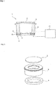
- Fig. 1 is a simplified front elevational cross-sectional view for depicting a vibration device according to a first embodiment of the present invention
- Fig. 2 is an exploded perspective view depicting a vibrating portion of the vibration device.
- a vibration device 1 includes a light-transmitting body 2 that is translucent or transparent, a hollow cylindrical body 3, and a piezoelectric element 4.
- the hollow cylindrical body 3 is hollow and has a substantially cylindrical form.
- the light-transmitting body 2, which has a platelike form, is fixed to the hollow cylindrical body 3 so as to close an opening at one end of the hollow cylindrical body 3.
- the light-transmitting body 2 is made of a translucent or transparent material, such as resin or glass.
- the light-transmitting body 2 is preferably transparent.
- the light-transmitting body 2 is fixed to the hollow cylindrical body 3 with a bonding agent layer 5 interposed therebetween.
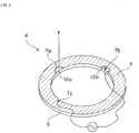
- the piezoelectric element 4 has a ringlike form.
- the piezoelectric element 4 includes a ring-shaped piezoelectric member 6.
- the ring-shaped piezoelectric member 6 is made of piezoelectric ceramics and has been subjected to poling treatment in the thickness direction.
- a first electrode 7 is disposed on one surface of the ring-shaped piezoelectric member 6, and a second electrode 8 is disposed on the other surface.
- the first electrode 7 has cutouts 7a and 7b.
- the cutouts 7a and 7b face the inner perimeter of the ring on one surface of the ring-shaped piezoelectric member 6.
- An electrode 10a which is independent of the first electrode 7, is disposed inside the cutout 7a.
- the electrode 10a serves as a feedback electrode to monitor a voltage generated by a piezoelectric effect during vibration.
- An electrode 10b is disposed inside the cutout 7b.
- the electrode 10b is electrically connected to the second electrode 8 via a portion of the inner perimeter of the ring-shaped piezoelectric member 6.
- An electrode section 7c is a portion of the first electrode 7, and an alternating current voltage is applied between the electrode 10b and the electrode section 7c to excite vibration. If a current measurement circuit described below is unnecessary, the electrode 10a, which serves as a feedback electrode, may be omitted.
- a liquid drop such as a water drop
- the vibration can move the water drop and remove the water drop by atomization.
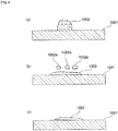
- Fig. 4 (a) to Fig. 4 (c) are schematic front elevational cross-sectional views for depicting a procedure of removing water drops by using such a known vibration device as is disclosed in Patent Document 1.
- Fig. 4 (a) represents a state in which a liquid drop 1002 sticks on a light-transmitting body 1001.
- the light-transmitting body 1001 is vibrated in this state in a known vibration device, the light-transmitting body 1001 is vibrated at or around a resonant frequency. Consequently, as depicted in Fig. 4 (b) , droplets 1002a, 1002a, and 1002a are dispersed and atomized from the liquid drop 1002, and a portion of the liquid drop 1002 is removed.
- the liquid drop 1002 since the liquid drop 1002 is subjected to vibration, the surface tension of the liquid drop 1002 is reduced on the surface of the light-transmitting body 1001, and the liquid drop 1002 spreads in the form of a liquid film. If vibration used for atomization continues to be applied, as depicted in Fig. 4 (c) , the liquid drop 1002 spreads in the form of a liquid film. If further vibration is applied, the liquid drop 1002 can be removed by atomization. However, as depicted in Fig. 4 (c) , the liquid drop 1002 sticks and spreads in the form of a liquid film during the atomization procedure. Thus, an issue of obstructing the field of view of the camera arises.
- a first step, a second step, and a third step below are performed to sweep a driving voltage described below.
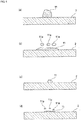
- Fig. 5 (a) to Fig. 5 (d) are schematic front elevational cross-sectional views depicting a procedure of removing liquid drops by the driving method according to the first embodiment of the present invention.
- a liquid drop 11 sticks on the light-transmitting body 2.
- the vibration device is driven as the first step.
- the liquid drop 11 spreads and a portion of the liquid drop 11 is removed in the form of droplets 11a, 11a, and 11a in the first step.
- the driving voltage is swept to atomize and remove liquid drops at a sweep speed in the range of 1 Hz to 50 Hz so as to cover a frequency range including both of the resonant frequency of the light-transmitting body without liquid drops sticking to the light-transmitting body 2 and the resonant frequency of the light-transmitting body with liquid drops sticking to the light-transmitting body 2. Since the driving voltage is swept in this way, the second step in which the light-transmitting body 2 vibrates more weakly than in the first step is performed after the first step. In the second step, as depicted in Fig.
- the light-transmitting body 2 is caused to vibrate more weakly than in the first step, which means that the light-transmitting body 2 is caused to vibrate in a manner such that the amplitude and the intensity of vibration of the light-transmitting body 2 are reduced.
- the vibration of the light-transmitting body 2 may be stopped in the second step.
- the light-transmitting body 2 is caused to vibrate more strongly in the third step than in the second step. Namely, further continuation of the sweep advances atomization, as depicted in Fig. 5 (d) . Thus, the liquid drop 11 is removed in the end.
- the liquid drop 11 is unlikely to stick to the light-transmitting body 2 in the form of a liquid film during the procedure of atomization.
- obstruction of the field of view of the camera is unlikely to occur.
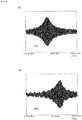
- the vibration-device driving method according to the present embodiment has a feature of sweeping in the above frequency range at a sweep speed in the range of 1 Hz to 50 Hz. This feature will be described with reference to Fig. 6 (a), Fig. 6 (b) , Fig. 7 (a), Fig. 7 (b) , and Fig. 8 .
- Fig. 6 (a), Fig. 6 (b) , Fig. 7 (a), Fig. 7 (b) , and Fig. 8 depict a temporal change in a displacement signal, which is equivalent to the amount of displacement of the light-transmitting body 2, at sweep speeds of 1 Hz, 5 Hz, 10 Hz, 20 Hz, and 100 Hz, respectively.
- Figs. 6 to 8 the sweep speed is varied, and the amount of time used for atomization is obtained.
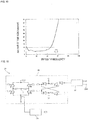
- the horizontal axis in Fig. 10 represents a frequency, which is equivalent to a sweep speed, and the vertical axis represents the amount of time used to remove a water drop having a volume of 5 ⁇ l as a liquid drop.
- Fig. 10 indicates that the amount of time used for atomization is equal to 10 seconds or shorter and water drops can efficiently be atomized if the sweep frequency is in the range of 1 Hz to 50 Hz.
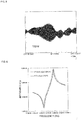
- Fig. 9 depicts resonance characteristics of the light-transmitting body 2 with and without liquid drops sticking to the light-transmitting body 2. As depicted in Fig. 9 , the resonant frequencies of the light-transmitting body 2 with and without sticking liquid drops are different.
- the driving voltage is swept to vibrate the piezoelectric element 4 at a sweep speed in the range of 1 Hz to 50 Hz as described above so as to cover a frequency range including both of the resonant frequency of the light-transmitting body 2 without liquid drops sticking to the light-transmitting body 2 and the resonant frequency of the light-transmitting body 2 with liquid drops sticking to the light-transmitting body 2.
- liquid drops can quickly be atomized as described above.
- the vibration device is driven as described above, and the atomization procedure is performed in three steps.
- the piezoelectric element is driven so as to atomize liquid drops sticking to the light-transmitting body.
- the light-transmitting body 2 is caused to vibrate more weakly than in the first step or caused to stop vibrating.
- the third step which follows the second step, the light-transmitting body 2 is caused to vibrate more strongly than in the second step, and liquid drops sticking to the light-transmitting body 2 are atomized again. Accordingly, as depicted in Fig. 5 (c) above, liquid drops are unlikely to spread in the form of a liquid film on the surface of the light-transmitting body 2 in the second step, and the field of view or the like of the camera is also unlikely to be obstructed.
- the vibration device 1 depicted in Fig. 1 includes a driving circuit 21 to achieve the driving method described above.
- Fig. 11 is a circuit diagram depicting an example of the driving circuit 21.
- the driving circuit 21 includes a voltage-controlled oscillator (VCO) 22, a driver circuit segment 23, and a current measurement circuit 24. Changing a control voltage applied to control terminals 22a of the VCO 22 causes the VCO 22 to transmit a predetermined voltage signal to the driver circuit segment 23.
- VCO voltage-controlled oscillator
- the driver circuit segment 23 drives the piezoelectric element 4 at the above sweep speed so as to sweep in a predetermined frequency range.
- the current measurement circuit 24 measures a current flowing through the piezoelectric element 4 and outputs a voltage in accordance with a value of the current.
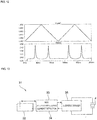
- the upper graph in Fig. 12 represents a voltage waveform that is input to the VCO 22.
- the lower graph in Fig. 12 represents a change in a current measured by the current measurement circuit 24.
- the driving voltage is continuously increased, for example, from 1.85 V to 1.90 V, and thereafter continuously decreased from 1.90 V to 1.85 V.
- the sweep is repeated by repeating the increase and decrease.
- the procedure of sweeping the frequency from the lower limit to the upper limit in the frequency sweep range preferably includes a step of increasing the sweep voltage and a step of decreasing the sweep voltage after the step of increasing the sweep voltage, and the increase and decrease in the sweep voltage are preferably performed in a continuous manner rather than in a stepwise manner.
- the input voltage to the VCO is preferably controlled so as to obtain a slope to form a triangular wave and is frequency modulated to drive the piezoelectric element 4.
- the peak height of the triangular wave determines the width of frequency variation of the VCO 22, and the center voltage of the triangular wave determines the center frequency of the CVO 22.
- a separately-excited oscillator circuit is formed and has the period of the triangular wave as a parameter in addition to the above parameters.
- a current in the piezoelectric element 4 is preferably monitored by using the current measurement circuit 24.
- Fixed parameters of the separately-excited oscillator circuit can be set by using the current signal because the current has the maximum at or around the maximum amount of displacement, which enables atomization. Accordingly, liquid drops are moved and atomized by using parameters optimized in accordance with the volume and the number of liquid drops.
- a circuit used for a vibration-device driving method according to the present invention is not limited, as depicted in Fig. 1 .
- FIG. 13 is a block diagram for depicting a driving circuit for a vibration device according to a second embodiment of the present invention.
- a driving circuit 31 includes a controller 32.
- the controller 32 is connected to a VCQ 33 and a current measurement circuit 34.
- the VCO 33 is connected to a H-bridge driver 35.
- the H-bridge driver 35 drives the piezoelectric element 4.
- a current flowing through the piezoelectric element 4 can be detected by using the current measurement circuit 34. The detected current value is supplied to the controller 32.
- the controller 32 includes a digital to analog (DA) converter and an analog to digital (AD) converter.
- the DA converter provides a voltage to control the VCO 33.
- the AD converter digitizes a current detected by the current measurement circuit 34. In this way, the driving circuit 31 including the controller 32 may be used.
- control can be performed by using a method in which a plurality of parameters are adjusted. For example, the following steps can be taken. 1) The frequency is swept in a wide frequency range to detect a peak current. 2) The piezoelectric element 4 is driven a plurality of times in a narrower frequency range around the center frequency at which the current peaks. 3) The first step is repeated, so that the center frequency is corrected. Repeating the above steps ensures atomization of liquid drops.
- Atomization is achieved by using the separately-excited oscillator circuit described above in the vibration device 1 according to the present embodiment. Consequently, the obstruction of the field of view due to a liquid film formed when a self-excited oscillator circuit is used is reduced or suppressed.
- a current may be measured by using the current measurement circuit 24, or a voltage may be monitored by using a feedback electrode.
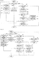
- Fig. 14 is a flowchart depicting a driving method according to a third embodiment as a whole. First, the initial settings are configured in step S1.
- Fig. 15 is a detailed flowchart of step S1, in which the initial settings are configured.
- parameter values are read from an internal memory in step S11A. It is determined in step S12A whether the parameter values in the internal memory are appropriate. If the parameter values are appropriate, initial values of the parameters are set to the parameter values recorded in the internal memory. If the internal memory is not appropriate, predetermined default values are adopted as the initial values of the parameters. Setting the initial values of the parameters completes the configuration of the initial settings.
- step S2 it is determined in step S2 whether a change in parameter values is requested. If a change is requested, parameter values are changed in step S4. Then, the status is set to a maximum current search state in step S5. Subsequently, the parameter values that have been changed are written to the internal memory in step S6. The process returns to step S2 again after step S6.
- step S2 If a change in parameter values is not requested in step S2, the maximum current search state or a sweep state is performed in accordance with the current status in step S7. The procedure for the maximum current search state is performed in step S8.
- Fig. 16 depicts a flowchart of the procedure for the maximum current search state.
- the process state is changed to a running state, a step width is calculated for a search voltage, adc_max is set to 0ct, and a timer is started in steps S21 to S24 in succession. If it is determined that the process state is the running state in step S7, it is determined in step S25 whether the timer reading has reached the end of a period. If the end of a period has been reached, the search voltage is output in step S26, an output voltage is read in step S27, and it is determined in step S28 whether the voltage that has been read is larger than adc_max.
- step S29 If the voltage that has been read is smaller than adc_max, the search voltage is increased in step S29. It is determined in step S30 whether the search voltage is equal to the maximum. If the search voltage is equal to the maximum, the process state is changed to the finished state in step S31. If the search voltage is not equal to the maximum, the process returns to step S7.
- adc_max is set in step S32 to the voltage that has been read. Then, the current search voltage is recorded in step S33.
- step S9 it is determined in step S9 whether the search for the maximum current is finished. If the search for the maximum current is finished, the status is set to the sweep state in step S10. If the search for the maximum current is not finished in step S9, the process returns to step S2.
- Fig. 17 depicts a flowchart of the procedure for the sweep state.
- a sweep voltage change timer is started to operate, and a sweep end timer is started in steps S42 to S44.
- a frequency sweep range is calculated by using the maximum current in step S45.
- a sweep voltage value is set to the minimum in the frequency sweep range in step S46. More specifically, the sweep voltage value is set to the value corresponding to the minimum in the frequency sweep range.
- step S47 If the current process state is the running state in step S41, it is determined in step S47 whether the reading of the sweep voltage change timer has reached the end of a period. If the end of a period has been reached, the sweep voltage value is output in step S48, and the voltage sweep direction in the next step is identified in step S49. If the voltage sweep direction is the direction in which the voltage is decreased, the sweep voltage value is decreased in step S50. Next, it is determined in step S51 whether the sweep voltage value is equal to the minimum in the frequency sweep range. If the sweep voltage value is equal to the minimum, the voltage sweep direction is changed to the upward direction in step S52.
- step S49 If the voltage sweep direction is the upward direction in step S49, the sweep voltage value is increased in step S53. Next, it is determined in step S54 whether the sweep voltage value is equal to the maximum in the frequency sweep range. If the sweep voltage value is equal to the maximum, the voltage sweep direction is changed to the downward direction in step S55. If the sweep voltage value is not equal to the maximum, the process is finished.
- step S56 If the reading of the sweep voltage change timer has not reached the end of a period in step S47, it is determined in step S56 whether the reading of the sweep end timer has reached the end of a period. If the end of a period has been reached, the process state is changed to the finished state in step S57, and the process is finished. If the reading of the sweep end timer has not reached the end of a period in step S56, the process returns to step S41.
- step S41 If the current process state is the finished state in step S41, the sweep voltage change timer is stopped, and the process state is changed to the initial state in steps S58 and S59. Then, the process is finished.
- step S12 it is determined in step S12 whether the sweep is finished. If the sweep is finished, the status is set to the maximum current search state in step S13. If the sweep is not finished, the process returns to step S2.
Landscapes
- Physics & Mathematics (AREA)
- General Physics & Mathematics (AREA)
- Optics & Photonics (AREA)
- Electromagnetism (AREA)
- Engineering & Computer Science (AREA)
- Multimedia (AREA)
- Signal Processing (AREA)
- Special Spraying Apparatus (AREA)
- Apparatuses For Generation Of Mechanical Vibrations (AREA)
- Camera Bodies And Camera Details Or Accessories (AREA)
- Structure And Mechanism Of Cameras (AREA)
- Accessories Of Cameras (AREA)
- Studio Devices (AREA)
- General Electrical Machinery Utilizing Piezoelectricity, Electrostriction Or Magnetostriction (AREA)
Claims (5)
- Ein Verfahren zum Ansteuern einer Vibrationsvorrichtung mit einem lichtübertragenden Körper und einem piezoelektrischen Element, das mit dem lichtübertragenden Körper verbunden ist, um den lichtübertragenden Körper in Vibration zu versetzen, wobei das Verfahren dazu konfiguriert ist, Flüssigkeitstropfen, die an dem lichtübertragenden Körper anhaften, zu zerstäuben und zu entfernen,
wobei eine Ansteuerspannung zum In-Vibration-Versetzen des piezoelektrischen Elements mit einer Wobbelgeschwindigkeit im Bereich von 1 Hz bis 50 Hz gewobbelt wird, um eine Vibrationsfrequenz des piezoelektrischen Elements zu wobbeln, so dass ein Frequenzbereich abgedeckt wird, der eine Resonanzfrequenz des lichtübertragenden Körpers ohne Flüssigkeitstropfen, die an dem lichtübertragenden Körper anhaften, und eine Resonanzfrequenz des lichtübertragenden Körpers mit den Flüssigkeitstropfen, die an dem lichtübertragenden Körper anhaften, umfasst. - Das Verfahren zum Ansteuern einer Vibrationsvorrichtung gemäß Anspruch 1,
wobei ein Wobbelvorgang in dem Frequenzbereich einen Schritt des Erhöhens einer Wobbelspannung und einen Schritt des Verringerns der Wobbelspannung nach dem Schritt des Erhöhens der Wobbelspannung umfasst, und ein Erhöhen und ein Verringern der Wobbelspannung auf kontinuierliche Weise durchgeführt werden. - Das Verfahren zum Ansteuern einer Vibrationsvorrichtung gemäß Anspruch 1 oder Anspruch 2,wobei ein erster Schritt, bei dem das piezoelektrische Element dahingehend angesteuert wird, Flüssigkeitstropfen, die an dem lichtübertragenden Körper anhaften, zu zerstäuben,ein zweiter Schritt, bei dem bewirkt wird, dass der lichtübertragende Körper schwächer als bei dem ersten Schritt vibriert oder das Vibrieren beendet, undein dritter Schritt, der auf den zweiten Schritt folgt, um Flüssigkeitstropfen, die an dem lichtübertragenden Körper anhaften, zu zerstäuben,durch ein Wobbeln in dem Frequenzbereich durchgeführt werden.
- Eine Vibrationsvorrichtung, die folgende Merkmale aufweist:einen lichtübertragenden Körper;ein piezoelektrisches Element, das mit dem lichtübertragenden Körper verbunden ist und den lichtübertragenden Körper in Vibration versetzt; undeine Steuerschaltung, die mit dem piezoelektrischen Element elektrisch verbunden ist und eine Ansteuerspannung zum In-Vibration-Versetzen des piezoelektrischen Elements mit einer Geschwindigkeit im Bereich von 1 Hz bis 50 Hz wobbelt, um eine Vibrationsfrequenz des piezoelektrischen Elements zu wobbeln, so dass ein Frequenzbereich abgedeckt wird, der eine Resonanzfrequenz des lichtübertragenden Körpers ohne Flüssigkeitstropfen, die an dem lichtübertragenden Körper anhaften, und eine Resonanzfrequenz des lichtübertragenden Körpers mit Flüssigkeitstropfen, die an dem lichtübertragenden Körper anhaften, umfasst.
- Die Vibrationsvorrichtung gemäß Anspruch 4, die ferner folgendes Merkmal aufweist:einen hohlen zylindrischen Körper, der den lichtübertragenden Körper mit dem piezoelektrischen Element verbindet,wobei das piezoelektrische Element eine ringähnliche Form aufweist, das piezoelektrische Element mit ringähnlicher Form an einem Ende des hohlen zylindrischen Körpers befestigt ist und der lichtübertragende Körper an dem anderen Ende des hohlen zylindrischen Körpers befestigt ist
Applications Claiming Priority (2)
| Application Number | Priority Date | Filing Date | Title |
|---|---|---|---|
| JP2017154334 | 2017-08-09 | ||
| PCT/JP2018/015236 WO2019030982A1 (ja) | 2017-08-09 | 2018-04-11 | 振動装置の駆動方法及び振動装置 |
Publications (3)
| Publication Number | Publication Date |
|---|---|
| EP3606029A1 EP3606029A1 (de) | 2020-02-05 |
| EP3606029A4 EP3606029A4 (de) | 2020-12-16 |
| EP3606029B1 true EP3606029B1 (de) | 2021-12-15 |
Family
ID=65272820
Family Applications (1)
| Application Number | Title | Priority Date | Filing Date |
|---|---|---|---|
| EP18843656.2A Active EP3606029B1 (de) | 2017-08-09 | 2018-04-11 | Verfahren zur ansteuerung einer vibrationsvorrichtung und vibrationsvorrichtung |
Country Status (5)
| Country | Link |
|---|---|
| US (1) | US10862405B2 (de) |
| EP (1) | EP3606029B1 (de) |
| JP (1) | JP6620914B2 (de) |
| CN (1) | CN110999272B (de) |
| WO (1) | WO2019030982A1 (de) |
Families Citing this family (11)
| Publication number | Priority date | Publication date | Assignee | Title |
|---|---|---|---|---|
| CN109076152B (zh) * | 2016-06-24 | 2020-09-15 | 株式会社村田制作所 | 振动装置以及摄像装置 |
| JP6601576B2 (ja) * | 2016-11-30 | 2019-11-06 | 株式会社村田製作所 | 振動装置、カメラ用水滴除去装置及びカメラ |
| JP6947299B2 (ja) * | 2018-05-22 | 2021-10-13 | 株式会社村田製作所 | 振動装置及び駆動装置 |
| WO2020170799A1 (ja) | 2019-02-21 | 2020-08-27 | 株式会社村田製作所 | グラフェントランジスタおよびその製造方法 |
| EP3934227B1 (de) * | 2019-04-26 | 2024-11-13 | Murata Manufacturing Co., Ltd. | Reinigungsvorrichtung, bildgebungseinheit mit reinigungsvorrichtung und reinigungsverfahren |
| WO2021038942A1 (ja) * | 2019-08-28 | 2021-03-04 | 株式会社村田製作所 | 振動装置及び光学検出装置 |
| CN113891820B (zh) * | 2020-03-19 | 2024-09-06 | 株式会社村田制作所 | 振动装置和振动控制方法 |
| EP3912735B1 (de) * | 2020-03-27 | 2023-09-27 | Murata Manufacturing Co., Ltd. | Vibrationsvorrichtung und vibrationssteuerungsverfahren |
| WO2021220539A1 (ja) | 2020-04-30 | 2021-11-04 | 株式会社村田製作所 | 洗浄装置、洗浄装置を備える撮像ユニット、および洗浄方法 |
| US20220219381A1 (en) * | 2021-01-08 | 2022-07-14 | Xerox Corporation | Building an object with a three-dimensional printer using vibrational energy |
| JP7768536B2 (ja) * | 2021-10-13 | 2025-11-12 | i-PRO株式会社 | 監視カメラ |
Family Cites Families (12)
| Publication number | Priority date | Publication date | Assignee | Title |
|---|---|---|---|---|
| JPH0295947A (ja) * | 1988-09-30 | 1990-04-06 | Aisin Seiki Co Ltd | 水滴除去装置 |
| JPH08183428A (ja) * | 1995-01-06 | 1996-07-16 | Nippon Sheet Glass Co Ltd | 能動型撥水窓装置 |
| BR0008730B1 (pt) * | 1999-03-05 | 2010-02-09 | mÉtodo para operar um atomizador vibratàrio e atomizador vibratàrio de lÍquido. | |
| JP5430367B2 (ja) * | 2009-11-26 | 2014-02-26 | キヤノン株式会社 | 塵埃除去装置および塵埃除去方法 |
| JP5693081B2 (ja) * | 2010-08-06 | 2015-04-01 | キヤノン株式会社 | 振動発生装置、その駆動方法、異物除去装置および光学装置 |
| JP2012138768A (ja) * | 2010-12-27 | 2012-07-19 | Hitachi Kokusai Electric Inc | ドーム型監視カメラシステム |
| US8899761B2 (en) * | 2011-03-23 | 2014-12-02 | Gentex Corporation | Lens cleaning apparatus |
| JP5948781B2 (ja) * | 2011-10-05 | 2016-07-06 | アイシン精機株式会社 | 水滴除去機能付カメラ |
| CN104069978A (zh) * | 2013-03-25 | 2014-10-01 | 厦门市骏耀光电科技有限公司 | 一种超声波雾化装置及雾化方法 |
| US10401618B2 (en) * | 2015-03-11 | 2019-09-03 | Texas Instruments Incorporated | Ultrasonic lens cleaning system with current sensing |
| GB201510166D0 (en) * | 2015-06-11 | 2015-07-29 | The Technology Partnership Plc | Spray delivery device |
| JP2017085276A (ja) * | 2015-10-26 | 2017-05-18 | オリンパス株式会社 | 液滴排除装置と、液滴排除装置を有する画像装置、及び液滴排除装置の制御方法、液滴排除装置の制御プログラム |
-
2018
- 2018-04-11 EP EP18843656.2A patent/EP3606029B1/de active Active
- 2018-04-11 WO PCT/JP2018/015236 patent/WO2019030982A1/ja not_active Ceased
- 2018-04-11 JP JP2019535587A patent/JP6620914B2/ja active Active
- 2018-04-11 CN CN201880051560.6A patent/CN110999272B/zh active Active
-
2020
- 2020-01-03 US US16/733,258 patent/US10862405B2/en active Active
Also Published As
| Publication number | Publication date |
|---|---|
| JP6620914B2 (ja) | 2019-12-18 |
| WO2019030982A1 (ja) | 2019-02-14 |
| JPWO2019030982A1 (ja) | 2019-12-26 |
| US20200144939A1 (en) | 2020-05-07 |
| US10862405B2 (en) | 2020-12-08 |
| EP3606029A4 (de) | 2020-12-16 |
| CN110999272A (zh) | 2020-04-10 |
| EP3606029A1 (de) | 2020-02-05 |
| CN110999272B (zh) | 2021-05-14 |
Similar Documents
| Publication | Publication Date | Title |
|---|---|---|
| EP3606029B1 (de) | Verfahren zur ansteuerung einer vibrationsvorrichtung und vibrationsvorrichtung | |
| JP6446501B2 (ja) | パッシブ共振回路のための駆動回路、および送信機デバイス | |
| US11865592B2 (en) | Cleaning device, imaging unit equipped with cleaning device, and cleaning method | |
| KR100366777B1 (ko) | 압전트랜스의 구동방법 및 구동회로 | |
| CN204724386U (zh) | 具有受控烟雾输出部的超声雾化器 | |
| KR20200100523A (ko) | 초음파 진동자 및 초음파 진동자를 사용한 초음파 세정 장치 | |
| US11770078B2 (en) | Vibration device and driving device | |
| CN113891820B (zh) | 振动装置和振动控制方法 | |
| WO2021131122A1 (ja) | 液滴除去装置および撮像ユニット | |
| US20240284801A1 (en) | Excitation circuit, vibration device, and vehicle | |
| JPH0118785B2 (de) | ||
| US20240269707A1 (en) | Excitation device, vibration device, vehicle, control method, and computer program | |
| JPH0479777A (ja) | 超音波モータの停止制御方法 | |
| US8471436B2 (en) | Piezoelectric element drive circuit and foreign substance removing apparatus | |
| JP2009233625A (ja) | 超音波振動子の駆動方法及び装置 | |
| US20250208408A1 (en) | Optical device and imaging unit provided with optical device | |
| JPH0295945A (ja) | 水滴除去装置 | |
| US7244377B2 (en) | Acoustic enhancement of particle fabrication by spinning | |
| KR20130014500A (ko) | 감소된 스페클 콘트라스트를 갖는 마이크로전자기계 시스템 | |
| JPH0211435A (ja) | 水滴除去装置 | |
| JPH03167055A (ja) | 振動子の駆動装置および該駆動装置を利用した水滴除去装置 | |
| KR20100062598A (ko) | 다중 주파수의 주기적인 변화를 통한 압전진동자의 구동 방법 및 장치 | |
| CN118975116A (zh) | 对振动装置进行控制的控制装置和对振动装置进行控制的方法 | |
| JPH03235742A (ja) | 自動車用ミラーの水滴除去装置 | |
| JP2000324860A5 (de) |
Legal Events
| Date | Code | Title | Description |
|---|---|---|---|
| STAA | Information on the status of an ep patent application or granted ep patent |
Free format text: STATUS: THE INTERNATIONAL PUBLICATION HAS BEEN MADE |
|
| PUAI | Public reference made under article 153(3) epc to a published international application that has entered the european phase |
Free format text: ORIGINAL CODE: 0009012 |
|
| STAA | Information on the status of an ep patent application or granted ep patent |
Free format text: STATUS: REQUEST FOR EXAMINATION WAS MADE |
|
| 17P | Request for examination filed |
Effective date: 20191022 |
|
| AK | Designated contracting states |
Kind code of ref document: A1 Designated state(s): AL AT BE BG CH CY CZ DE DK EE ES FI FR GB GR HR HU IE IS IT LI LT LU LV MC MK MT NL NO PL PT RO RS SE SI SK SM TR |
|
| AX | Request for extension of the european patent |
Extension state: BA ME |
|
| DAV | Request for validation of the european patent (deleted) | ||
| DAX | Request for extension of the european patent (deleted) | ||
| A4 | Supplementary search report drawn up and despatched |
Effective date: 20201113 |
|
| RIC1 | Information provided on ipc code assigned before grant |
Ipc: G03B 17/56 20060101ALI20201109BHEP Ipc: H04N 7/18 20060101ALI20201109BHEP Ipc: G02B 27/00 20060101ALI20201109BHEP Ipc: H04N 5/225 20060101AFI20201109BHEP |
|
| GRAP | Despatch of communication of intention to grant a patent |
Free format text: ORIGINAL CODE: EPIDOSNIGR1 |
|
| STAA | Information on the status of an ep patent application or granted ep patent |
Free format text: STATUS: GRANT OF PATENT IS INTENDED |
|
| RIC1 | Information provided on ipc code assigned before grant |
Ipc: H04N 5/225 20060101AFI20210528BHEP Ipc: G03B 17/56 20210101ALI20210528BHEP Ipc: H04N 7/18 20060101ALI20210528BHEP Ipc: G02B 27/00 20060101ALI20210528BHEP Ipc: B08B 7/02 20060101ALI20210528BHEP Ipc: B08B 17/02 20060101ALI20210528BHEP |
|
| INTG | Intention to grant announced |
Effective date: 20210701 |
|
| GRAS | Grant fee paid |
Free format text: ORIGINAL CODE: EPIDOSNIGR3 |
|
| GRAA | (expected) grant |
Free format text: ORIGINAL CODE: 0009210 |
|
| STAA | Information on the status of an ep patent application or granted ep patent |
Free format text: STATUS: THE PATENT HAS BEEN GRANTED |
|
| AK | Designated contracting states |
Kind code of ref document: B1 Designated state(s): AL AT BE BG CH CY CZ DE DK EE ES FI FR GB GR HR HU IE IS IT LI LT LU LV MC MK MT NL NO PL PT RO RS SE SI SK SM TR |
|
| REG | Reference to a national code |
Ref country code: GB Ref legal event code: FG4D Ref country code: CH Ref legal event code: EP |
|
| REG | Reference to a national code |
Ref country code: IE Ref legal event code: FG4D Ref country code: DE Ref legal event code: R096 Ref document number: 602018028359 Country of ref document: DE |
|
| REG | Reference to a national code |
Ref country code: AT Ref legal event code: REF Ref document number: 1456348 Country of ref document: AT Kind code of ref document: T Effective date: 20220115 |
|
| REG | Reference to a national code |
Ref country code: LT Ref legal event code: MG9D |
|
| REG | Reference to a national code |
Ref country code: NL Ref legal event code: MP Effective date: 20211215 |
|
| PG25 | Lapsed in a contracting state [announced via postgrant information from national office to epo] |
Ref country code: RS Free format text: LAPSE BECAUSE OF FAILURE TO SUBMIT A TRANSLATION OF THE DESCRIPTION OR TO PAY THE FEE WITHIN THE PRESCRIBED TIME-LIMIT Effective date: 20211215 Ref country code: LT Free format text: LAPSE BECAUSE OF FAILURE TO SUBMIT A TRANSLATION OF THE DESCRIPTION OR TO PAY THE FEE WITHIN THE PRESCRIBED TIME-LIMIT Effective date: 20211215 Ref country code: FI Free format text: LAPSE BECAUSE OF FAILURE TO SUBMIT A TRANSLATION OF THE DESCRIPTION OR TO PAY THE FEE WITHIN THE PRESCRIBED TIME-LIMIT Effective date: 20211215 Ref country code: BG Free format text: LAPSE BECAUSE OF FAILURE TO SUBMIT A TRANSLATION OF THE DESCRIPTION OR TO PAY THE FEE WITHIN THE PRESCRIBED TIME-LIMIT Effective date: 20220315 |
|
| REG | Reference to a national code |
Ref country code: AT Ref legal event code: MK05 Ref document number: 1456348 Country of ref document: AT Kind code of ref document: T Effective date: 20211215 |
|
| PG25 | Lapsed in a contracting state [announced via postgrant information from national office to epo] |
Ref country code: SE Free format text: LAPSE BECAUSE OF FAILURE TO SUBMIT A TRANSLATION OF THE DESCRIPTION OR TO PAY THE FEE WITHIN THE PRESCRIBED TIME-LIMIT Effective date: 20211215 Ref country code: NO Free format text: LAPSE BECAUSE OF FAILURE TO SUBMIT A TRANSLATION OF THE DESCRIPTION OR TO PAY THE FEE WITHIN THE PRESCRIBED TIME-LIMIT Effective date: 20220315 Ref country code: LV Free format text: LAPSE BECAUSE OF FAILURE TO SUBMIT A TRANSLATION OF THE DESCRIPTION OR TO PAY THE FEE WITHIN THE PRESCRIBED TIME-LIMIT Effective date: 20211215 Ref country code: HR Free format text: LAPSE BECAUSE OF FAILURE TO SUBMIT A TRANSLATION OF THE DESCRIPTION OR TO PAY THE FEE WITHIN THE PRESCRIBED TIME-LIMIT Effective date: 20211215 Ref country code: GR Free format text: LAPSE BECAUSE OF FAILURE TO SUBMIT A TRANSLATION OF THE DESCRIPTION OR TO PAY THE FEE WITHIN THE PRESCRIBED TIME-LIMIT Effective date: 20220316 |
|
| PG25 | Lapsed in a contracting state [announced via postgrant information from national office to epo] |
Ref country code: NL Free format text: LAPSE BECAUSE OF FAILURE TO SUBMIT A TRANSLATION OF THE DESCRIPTION OR TO PAY THE FEE WITHIN THE PRESCRIBED TIME-LIMIT Effective date: 20211215 |
|
| PG25 | Lapsed in a contracting state [announced via postgrant information from national office to epo] |
Ref country code: SM Free format text: LAPSE BECAUSE OF FAILURE TO SUBMIT A TRANSLATION OF THE DESCRIPTION OR TO PAY THE FEE WITHIN THE PRESCRIBED TIME-LIMIT Effective date: 20211215 Ref country code: SK Free format text: LAPSE BECAUSE OF FAILURE TO SUBMIT A TRANSLATION OF THE DESCRIPTION OR TO PAY THE FEE WITHIN THE PRESCRIBED TIME-LIMIT Effective date: 20211215 Ref country code: RO Free format text: LAPSE BECAUSE OF FAILURE TO SUBMIT A TRANSLATION OF THE DESCRIPTION OR TO PAY THE FEE WITHIN THE PRESCRIBED TIME-LIMIT Effective date: 20211215 Ref country code: PT Free format text: LAPSE BECAUSE OF FAILURE TO SUBMIT A TRANSLATION OF THE DESCRIPTION OR TO PAY THE FEE WITHIN THE PRESCRIBED TIME-LIMIT Effective date: 20220418 Ref country code: ES Free format text: LAPSE BECAUSE OF FAILURE TO SUBMIT A TRANSLATION OF THE DESCRIPTION OR TO PAY THE FEE WITHIN THE PRESCRIBED TIME-LIMIT Effective date: 20211215 Ref country code: EE Free format text: LAPSE BECAUSE OF FAILURE TO SUBMIT A TRANSLATION OF THE DESCRIPTION OR TO PAY THE FEE WITHIN THE PRESCRIBED TIME-LIMIT Effective date: 20211215 Ref country code: CZ Free format text: LAPSE BECAUSE OF FAILURE TO SUBMIT A TRANSLATION OF THE DESCRIPTION OR TO PAY THE FEE WITHIN THE PRESCRIBED TIME-LIMIT Effective date: 20211215 |
|
| PG25 | Lapsed in a contracting state [announced via postgrant information from national office to epo] |
Ref country code: PL Free format text: LAPSE BECAUSE OF FAILURE TO SUBMIT A TRANSLATION OF THE DESCRIPTION OR TO PAY THE FEE WITHIN THE PRESCRIBED TIME-LIMIT Effective date: 20211215 Ref country code: AT Free format text: LAPSE BECAUSE OF FAILURE TO SUBMIT A TRANSLATION OF THE DESCRIPTION OR TO PAY THE FEE WITHIN THE PRESCRIBED TIME-LIMIT Effective date: 20211215 |
|
| REG | Reference to a national code |
Ref country code: DE Ref legal event code: R097 Ref document number: 602018028359 Country of ref document: DE |
|
| PG25 | Lapsed in a contracting state [announced via postgrant information from national office to epo] |
Ref country code: IS Free format text: LAPSE BECAUSE OF FAILURE TO SUBMIT A TRANSLATION OF THE DESCRIPTION OR TO PAY THE FEE WITHIN THE PRESCRIBED TIME-LIMIT Effective date: 20220415 |
|
| PLBE | No opposition filed within time limit |
Free format text: ORIGINAL CODE: 0009261 |
|
| STAA | Information on the status of an ep patent application or granted ep patent |
Free format text: STATUS: NO OPPOSITION FILED WITHIN TIME LIMIT |
|
| PG25 | Lapsed in a contracting state [announced via postgrant information from national office to epo] |
Ref country code: DK Free format text: LAPSE BECAUSE OF FAILURE TO SUBMIT A TRANSLATION OF THE DESCRIPTION OR TO PAY THE FEE WITHIN THE PRESCRIBED TIME-LIMIT Effective date: 20211215 Ref country code: AL Free format text: LAPSE BECAUSE OF FAILURE TO SUBMIT A TRANSLATION OF THE DESCRIPTION OR TO PAY THE FEE WITHIN THE PRESCRIBED TIME-LIMIT Effective date: 20211215 |
|
| 26N | No opposition filed |
Effective date: 20220916 |
|
| REG | Reference to a national code |
Ref country code: DE Ref legal event code: R079 Ref document number: 602018028359 Country of ref document: DE Free format text: PREVIOUS MAIN CLASS: H04N0005225000 Ipc: H04N0023000000 |
|
| PG25 | Lapsed in a contracting state [announced via postgrant information from national office to epo] |
Ref country code: SI Free format text: LAPSE BECAUSE OF FAILURE TO SUBMIT A TRANSLATION OF THE DESCRIPTION OR TO PAY THE FEE WITHIN THE PRESCRIBED TIME-LIMIT Effective date: 20211215 |
|
| REG | Reference to a national code |
Ref country code: CH Ref legal event code: PL |
|
| GBPC | Gb: european patent ceased through non-payment of renewal fee |
Effective date: 20220411 |
|
| REG | Reference to a national code |
Ref country code: BE Ref legal event code: MM Effective date: 20220430 |
|
| PG25 | Lapsed in a contracting state [announced via postgrant information from national office to epo] |
Ref country code: MC Free format text: LAPSE BECAUSE OF FAILURE TO SUBMIT A TRANSLATION OF THE DESCRIPTION OR TO PAY THE FEE WITHIN THE PRESCRIBED TIME-LIMIT Effective date: 20211215 Ref country code: LU Free format text: LAPSE BECAUSE OF NON-PAYMENT OF DUE FEES Effective date: 20220411 Ref country code: LI Free format text: LAPSE BECAUSE OF NON-PAYMENT OF DUE FEES Effective date: 20220430 Ref country code: GB Free format text: LAPSE BECAUSE OF NON-PAYMENT OF DUE FEES Effective date: 20220411 Ref country code: CH Free format text: LAPSE BECAUSE OF NON-PAYMENT OF DUE FEES Effective date: 20220430 |
|
| PG25 | Lapsed in a contracting state [announced via postgrant information from national office to epo] |
Ref country code: BE Free format text: LAPSE BECAUSE OF NON-PAYMENT OF DUE FEES Effective date: 20220430 |
|
| PG25 | Lapsed in a contracting state [announced via postgrant information from national office to epo] |
Ref country code: IE Free format text: LAPSE BECAUSE OF NON-PAYMENT OF DUE FEES Effective date: 20220411 |
|
| PG25 | Lapsed in a contracting state [announced via postgrant information from national office to epo] |
Ref country code: IT Free format text: LAPSE BECAUSE OF FAILURE TO SUBMIT A TRANSLATION OF THE DESCRIPTION OR TO PAY THE FEE WITHIN THE PRESCRIBED TIME-LIMIT Effective date: 20211215 |
|
| PG25 | Lapsed in a contracting state [announced via postgrant information from national office to epo] |
Ref country code: MK Free format text: LAPSE BECAUSE OF FAILURE TO SUBMIT A TRANSLATION OF THE DESCRIPTION OR TO PAY THE FEE WITHIN THE PRESCRIBED TIME-LIMIT Effective date: 20211215 Ref country code: CY Free format text: LAPSE BECAUSE OF FAILURE TO SUBMIT A TRANSLATION OF THE DESCRIPTION OR TO PAY THE FEE WITHIN THE PRESCRIBED TIME-LIMIT Effective date: 20211215 |
|
| PG25 | Lapsed in a contracting state [announced via postgrant information from national office to epo] |
Ref country code: HU Free format text: LAPSE BECAUSE OF FAILURE TO SUBMIT A TRANSLATION OF THE DESCRIPTION OR TO PAY THE FEE WITHIN THE PRESCRIBED TIME-LIMIT; INVALID AB INITIO Effective date: 20180411 |
|
| PG25 | Lapsed in a contracting state [announced via postgrant information from national office to epo] |
Ref country code: MT Free format text: LAPSE BECAUSE OF FAILURE TO SUBMIT A TRANSLATION OF THE DESCRIPTION OR TO PAY THE FEE WITHIN THE PRESCRIBED TIME-LIMIT Effective date: 20211215 |
|
| PGFP | Annual fee paid to national office [announced via postgrant information from national office to epo] |
Ref country code: DE Payment date: 20250422 Year of fee payment: 8 |
|
| PGFP | Annual fee paid to national office [announced via postgrant information from national office to epo] |
Ref country code: FR Payment date: 20250425 Year of fee payment: 8 |
|
| PG25 | Lapsed in a contracting state [announced via postgrant information from national office to epo] |
Ref country code: TR Free format text: LAPSE BECAUSE OF FAILURE TO SUBMIT A TRANSLATION OF THE DESCRIPTION OR TO PAY THE FEE WITHIN THE PRESCRIBED TIME-LIMIT Effective date: 20211215 |