EP3606029B1 - Method for driving vibration device, and vibration device - Google Patents
Method for driving vibration device, and vibration device Download PDFInfo
- Publication number
- EP3606029B1 EP3606029B1 EP18843656.2A EP18843656A EP3606029B1 EP 3606029 B1 EP3606029 B1 EP 3606029B1 EP 18843656 A EP18843656 A EP 18843656A EP 3606029 B1 EP3606029 B1 EP 3606029B1
- Authority
- EP
- European Patent Office
- Prior art keywords
- light
- transmitting body
- sweep
- piezoelectric element
- voltage
- Prior art date
- Legal status (The legal status is an assumption and is not a legal conclusion. Google has not performed a legal analysis and makes no representation as to the accuracy of the status listed.)
- Active
Links
- 238000000034 method Methods 0.000 title claims description 66
- 239000007788 liquid Substances 0.000 claims description 62
- 230000003247 decreasing effect Effects 0.000 claims description 8
- 230000007423 decrease Effects 0.000 claims description 5
- 238000010408 sweeping Methods 0.000 claims description 4
- 238000000889 atomisation Methods 0.000 description 15
- XLYOFNOQVPJJNP-UHFFFAOYSA-N water Substances O XLYOFNOQVPJJNP-UHFFFAOYSA-N 0.000 description 15
- 238000005259 measurement Methods 0.000 description 11
- 238000006073 displacement reaction Methods 0.000 description 9
- 238000010586 diagram Methods 0.000 description 4
- 239000007767 bonding agent Substances 0.000 description 2
- 239000000919 ceramic Substances 0.000 description 2
- 230000000694 effects Effects 0.000 description 2
- 230000006870 function Effects 0.000 description 2
- 102220646157 Actin-like protein 7A_S12A_mutation Human genes 0.000 description 1
- 239000011521 glass Substances 0.000 description 1
- 239000011347 resin Substances 0.000 description 1
- 229920005989 resin Polymers 0.000 description 1
- 102200048773 rs2224391 Human genes 0.000 description 1
- 238000006467 substitution reaction Methods 0.000 description 1
- 230000002123 temporal effect Effects 0.000 description 1
- 239000012780 transparent material Substances 0.000 description 1
Images


Classifications
-
- H—ELECTRICITY
- H02—GENERATION; CONVERSION OR DISTRIBUTION OF ELECTRIC POWER
- H02N—ELECTRIC MACHINES NOT OTHERWISE PROVIDED FOR
- H02N2/00—Electric machines in general using piezoelectric effect, electrostriction or magnetostriction
- H02N2/02—Electric machines in general using piezoelectric effect, electrostriction or magnetostriction producing linear motion, e.g. actuators; Linear positioners ; Linear motors
- H02N2/026—Electric machines in general using piezoelectric effect, electrostriction or magnetostriction producing linear motion, e.g. actuators; Linear positioners ; Linear motors by pressing one or more vibrators against the driven body
-
- G—PHYSICS
- G02—OPTICS
- G02B—OPTICAL ELEMENTS, SYSTEMS OR APPARATUS
- G02B27/00—Optical systems or apparatus not provided for by any of the groups G02B1/00 - G02B26/00, G02B30/00
- G02B27/0006—Optical systems or apparatus not provided for by any of the groups G02B1/00 - G02B26/00, G02B30/00 with means to keep optical surfaces clean, e.g. by preventing or removing dirt, stains, contamination, condensation
-
- B—PERFORMING OPERATIONS; TRANSPORTING
- B08—CLEANING
- B08B—CLEANING IN GENERAL; PREVENTION OF FOULING IN GENERAL
- B08B17/00—Methods preventing fouling
- B08B17/02—Preventing deposition of fouling or of dust
-
- B—PERFORMING OPERATIONS; TRANSPORTING
- B08—CLEANING
- B08B—CLEANING IN GENERAL; PREVENTION OF FOULING IN GENERAL
- B08B7/00—Cleaning by methods not provided for in a single other subclass or a single group in this subclass
- B08B7/02—Cleaning by methods not provided for in a single other subclass or a single group in this subclass by distortion, beating, or vibration of the surface to be cleaned
-
- G—PHYSICS
- G03—PHOTOGRAPHY; CINEMATOGRAPHY; ANALOGOUS TECHNIQUES USING WAVES OTHER THAN OPTICAL WAVES; ELECTROGRAPHY; HOLOGRAPHY
- G03B—APPARATUS OR ARRANGEMENTS FOR TAKING PHOTOGRAPHS OR FOR PROJECTING OR VIEWING THEM; APPARATUS OR ARRANGEMENTS EMPLOYING ANALOGOUS TECHNIQUES USING WAVES OTHER THAN OPTICAL WAVES; ACCESSORIES THEREFOR
- G03B17/00—Details of cameras or camera bodies; Accessories therefor
- G03B17/02—Bodies
- G03B17/08—Waterproof bodies or housings
-
- H—ELECTRICITY
- H04—ELECTRIC COMMUNICATION TECHNIQUE
- H04N—PICTORIAL COMMUNICATION, e.g. TELEVISION
- H04N23/00—Cameras or camera modules comprising electronic image sensors; Control thereof
-
- H—ELECTRICITY
- H04—ELECTRIC COMMUNICATION TECHNIQUE
- H04N—PICTORIAL COMMUNICATION, e.g. TELEVISION
- H04N23/00—Cameras or camera modules comprising electronic image sensors; Control thereof
- H04N23/50—Constructional details
- H04N23/52—Elements optimising image sensor operation, e.g. for electromagnetic interference [EMI] protection or temperature control by heat transfer or cooling elements
-
- G—PHYSICS
- G03—PHOTOGRAPHY; CINEMATOGRAPHY; ANALOGOUS TECHNIQUES USING WAVES OTHER THAN OPTICAL WAVES; ELECTROGRAPHY; HOLOGRAPHY
- G03B—APPARATUS OR ARRANGEMENTS FOR TAKING PHOTOGRAPHS OR FOR PROJECTING OR VIEWING THEM; APPARATUS OR ARRANGEMENTS EMPLOYING ANALOGOUS TECHNIQUES USING WAVES OTHER THAN OPTICAL WAVES; ACCESSORIES THEREFOR
- G03B17/00—Details of cameras or camera bodies; Accessories therefor
- G03B17/56—Accessories
-
- G—PHYSICS
- G03—PHOTOGRAPHY; CINEMATOGRAPHY; ANALOGOUS TECHNIQUES USING WAVES OTHER THAN OPTICAL WAVES; ELECTROGRAPHY; HOLOGRAPHY
- G03B—APPARATUS OR ARRANGEMENTS FOR TAKING PHOTOGRAPHS OR FOR PROJECTING OR VIEWING THEM; APPARATUS OR ARRANGEMENTS EMPLOYING ANALOGOUS TECHNIQUES USING WAVES OTHER THAN OPTICAL WAVES; ACCESSORIES THEREFOR
- G03B2205/00—Adjustment of optical system relative to image or object surface other than for focusing
- G03B2205/0053—Driving means for the movement of one or more optical element
- G03B2205/0061—Driving means for the movement of one or more optical element using piezoelectric actuators
-
- H—ELECTRICITY
- H04—ELECTRIC COMMUNICATION TECHNIQUE
- H04N—PICTORIAL COMMUNICATION, e.g. TELEVISION
- H04N23/00—Cameras or camera modules comprising electronic image sensors; Control thereof
- H04N23/50—Constructional details
- H04N23/55—Optical parts specially adapted for electronic image sensors; Mounting thereof
Definitions
- the present invention relates to a method of driving a vibration device having a function of removing liquid drops, such as water drops, and relates to the vibration device.
- Patent Document 1 discloses a camera having a function of removing raindrops.
- a translucent or transparent dome-shaped cover is disposed in front of a camera body.
- a hollow cylinder is connected to the dome-shaped cover, and a piezoelectric ceramics vibrator is fixed to the hollow cylinder.
- the piezoelectric vibrator vibrates the hollow cylinder and the dome-shaped cover. The vibration atomizes and removes water drops.
- vibration at or around the resonant frequency of the dome-shaped cover can efficiently remove water drops.
- Patent Document 1 when the piezoelectric vibrator is driven, the frequency of an alternating current voltage is increased to the maximum frequency and then swept around resonant frequencies while the frequency is being decreased.
- Patent Document 1 discloses Pattern A in which the frequency is swept with a sawtooth waveform and Pattern B in which the frequency is increased to the maximum frequency and then swept around a plurality of resonant frequencies in descending order of frequency while the frequency is being decreased.
- Patent Document 1 Japanese Unexamined Patent Application Publication No. 2012-138768
- the driving method described in Patent Document 1 has limits to the sweep range in which the frequency is swept. If an amplitude minimum exists even at the frequency lower limit, water drops or the like may remain. Accordingly, the frequency is repeatedly swept to obtain a sawtoothlike change in Pattern A, and the sweep range is widened by using a plurality of resonance points in Pattern B.
- An object of the present invention is to provide a method of driving a vibration device and to provide a vibration device.
- the method and the device are unlikely to cause obstruction of the field of view due to a spreading liquid film while liquid drops sticking to a light-transmitting body are removed.
- the present invention provides a method of driving a vibration device having a light-transmitting body and a piezoelectric element connected to the light-transmitting body so as to vibrate the light-transmitting body.
- the method is configured to atomize and remove liquid drops sticking to the light-transmitting body.
- a driving voltage for vibrating the piezoelectric element is swept at a sweep speed in a range of 1 Hz to 50 Hz so as to sweep a vibration frequency of the piezoelectric element to cover a frequency range including both of a resonant frequency of the light-transmitting body without liquid drops sticking to the light-transmitting body and a resonant frequency of the light-transmitting body with the liquid drops sticking to the light-transmitting body.
- a procedure of sweeping in the frequency range includes a step of increasing a sweep voltage and a step of decreasing the sweep voltage after the step of increasing the sweep voltage, and an increase and a decrease in the sweep voltage are performed in a continuous manner.
- a first step in which the piezoelectric element is driven so as to atomize liquid drops sticking to the light-transmitting body, a second step in which the light-transmitting body is caused to vibrate more weakly than in the first step or caused to stop vibrating, and a third step, which follows the second step, to atomize liquid drops sticking to the light-transmitting body are performed by a sweep in the frequency range.
- a vibration device includes a light-transmitting body, a piezoelectric element that is connected to the light-transmitting body and that vibrates the light-transmitting body, and a control circuit that is electrically connected to the piezoelectric element and that sweeps at a speed in a range of 1 Hz to 50 Hz a driving voltage for vibrating the piezoelectric element so as to sweep a vibration frequency of the piezoelectric element to cover a frequency range including a resonant frequency of the light-transmitting body and a resonant frequency of the light-transmitting body with liquid drops sticking to the light-transmitting body.
- the vibration device further includes a hollow cylindrical body connecting the light-transmitting body to the piezoelectric element.
- the piezoelectric element has a ringlike form.
- the piezoelectric element having a ringlike form is fixed to one end of the hollow cylindrical body, and the light-transmitting body is fixed to the other end of the hollow cylindrical body.
- the vibration-device driving method and the vibration device of the present invention while liquid drops sticking to a light-transmitting body are atomized and removed, a liquid film is unlikely to spread on the surface of the light-transmitting body.
- a liquid film is unlikely to spread on the surface of the light-transmitting body.
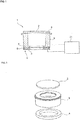
- Fig. 1 is a simplified front elevational cross-sectional view for depicting a vibration device according to a first embodiment of the present invention
- Fig. 2 is an exploded perspective view depicting a vibrating portion of the vibration device.
- a vibration device 1 includes a light-transmitting body 2 that is translucent or transparent, a hollow cylindrical body 3, and a piezoelectric element 4.
- the hollow cylindrical body 3 is hollow and has a substantially cylindrical form.
- the light-transmitting body 2, which has a platelike form, is fixed to the hollow cylindrical body 3 so as to close an opening at one end of the hollow cylindrical body 3.
- the light-transmitting body 2 is made of a translucent or transparent material, such as resin or glass.
- the light-transmitting body 2 is preferably transparent.
- the light-transmitting body 2 is fixed to the hollow cylindrical body 3 with a bonding agent layer 5 interposed therebetween.
- the piezoelectric element 4 has a ringlike form.
- the piezoelectric element 4 includes a ring-shaped piezoelectric member 6.
- the ring-shaped piezoelectric member 6 is made of piezoelectric ceramics and has been subjected to poling treatment in the thickness direction.
- a first electrode 7 is disposed on one surface of the ring-shaped piezoelectric member 6, and a second electrode 8 is disposed on the other surface.
- the first electrode 7 has cutouts 7a and 7b.
- the cutouts 7a and 7b face the inner perimeter of the ring on one surface of the ring-shaped piezoelectric member 6.
- An electrode 10a which is independent of the first electrode 7, is disposed inside the cutout 7a.
- the electrode 10a serves as a feedback electrode to monitor a voltage generated by a piezoelectric effect during vibration.
- An electrode 10b is disposed inside the cutout 7b.
- the electrode 10b is electrically connected to the second electrode 8 via a portion of the inner perimeter of the ring-shaped piezoelectric member 6.
- An electrode section 7c is a portion of the first electrode 7, and an alternating current voltage is applied between the electrode 10b and the electrode section 7c to excite vibration. If a current measurement circuit described below is unnecessary, the electrode 10a, which serves as a feedback electrode, may be omitted.
- a liquid drop such as a water drop
- the vibration can move the water drop and remove the water drop by atomization.
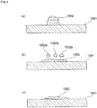
- Fig. 4 (a) to Fig. 4 (c) are schematic front elevational cross-sectional views for depicting a procedure of removing water drops by using such a known vibration device as is disclosed in Patent Document 1.
- Fig. 4 (a) represents a state in which a liquid drop 1002 sticks on a light-transmitting body 1001.
- the light-transmitting body 1001 is vibrated in this state in a known vibration device, the light-transmitting body 1001 is vibrated at or around a resonant frequency. Consequently, as depicted in Fig. 4 (b) , droplets 1002a, 1002a, and 1002a are dispersed and atomized from the liquid drop 1002, and a portion of the liquid drop 1002 is removed.
- the liquid drop 1002 since the liquid drop 1002 is subjected to vibration, the surface tension of the liquid drop 1002 is reduced on the surface of the light-transmitting body 1001, and the liquid drop 1002 spreads in the form of a liquid film. If vibration used for atomization continues to be applied, as depicted in Fig. 4 (c) , the liquid drop 1002 spreads in the form of a liquid film. If further vibration is applied, the liquid drop 1002 can be removed by atomization. However, as depicted in Fig. 4 (c) , the liquid drop 1002 sticks and spreads in the form of a liquid film during the atomization procedure. Thus, an issue of obstructing the field of view of the camera arises.
- a first step, a second step, and a third step below are performed to sweep a driving voltage described below.
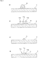
- Fig. 5 (a) to Fig. 5 (d) are schematic front elevational cross-sectional views depicting a procedure of removing liquid drops by the driving method according to the first embodiment of the present invention.
- a liquid drop 11 sticks on the light-transmitting body 2.
- the vibration device is driven as the first step.
- the liquid drop 11 spreads and a portion of the liquid drop 11 is removed in the form of droplets 11a, 11a, and 11a in the first step.
- the driving voltage is swept to atomize and remove liquid drops at a sweep speed in the range of 1 Hz to 50 Hz so as to cover a frequency range including both of the resonant frequency of the light-transmitting body without liquid drops sticking to the light-transmitting body 2 and the resonant frequency of the light-transmitting body with liquid drops sticking to the light-transmitting body 2. Since the driving voltage is swept in this way, the second step in which the light-transmitting body 2 vibrates more weakly than in the first step is performed after the first step. In the second step, as depicted in Fig.
- the light-transmitting body 2 is caused to vibrate more weakly than in the first step, which means that the light-transmitting body 2 is caused to vibrate in a manner such that the amplitude and the intensity of vibration of the light-transmitting body 2 are reduced.
- the vibration of the light-transmitting body 2 may be stopped in the second step.
- the light-transmitting body 2 is caused to vibrate more strongly in the third step than in the second step. Namely, further continuation of the sweep advances atomization, as depicted in Fig. 5 (d) . Thus, the liquid drop 11 is removed in the end.
- the liquid drop 11 is unlikely to stick to the light-transmitting body 2 in the form of a liquid film during the procedure of atomization.
- obstruction of the field of view of the camera is unlikely to occur.
- the vibration-device driving method according to the present embodiment has a feature of sweeping in the above frequency range at a sweep speed in the range of 1 Hz to 50 Hz. This feature will be described with reference to Fig. 6 (a), Fig. 6 (b) , Fig. 7 (a), Fig. 7 (b) , and Fig. 8 .
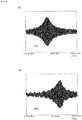
- Fig. 6 (a), Fig. 6 (b) , Fig. 7 (a), Fig. 7 (b) , and Fig. 8 depict a temporal change in a displacement signal, which is equivalent to the amount of displacement of the light-transmitting body 2, at sweep speeds of 1 Hz, 5 Hz, 10 Hz, 20 Hz, and 100 Hz, respectively.
- Figs. 6 to 8 the sweep speed is varied, and the amount of time used for atomization is obtained.
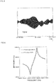
- the horizontal axis in Fig. 10 represents a frequency, which is equivalent to a sweep speed, and the vertical axis represents the amount of time used to remove a water drop having a volume of 5 ⁇ l as a liquid drop.
- Fig. 10 indicates that the amount of time used for atomization is equal to 10 seconds or shorter and water drops can efficiently be atomized if the sweep frequency is in the range of 1 Hz to 50 Hz.
- Fig. 9 depicts resonance characteristics of the light-transmitting body 2 with and without liquid drops sticking to the light-transmitting body 2. As depicted in Fig. 9 , the resonant frequencies of the light-transmitting body 2 with and without sticking liquid drops are different.
- the driving voltage is swept to vibrate the piezoelectric element 4 at a sweep speed in the range of 1 Hz to 50 Hz as described above so as to cover a frequency range including both of the resonant frequency of the light-transmitting body 2 without liquid drops sticking to the light-transmitting body 2 and the resonant frequency of the light-transmitting body 2 with liquid drops sticking to the light-transmitting body 2.
- liquid drops can quickly be atomized as described above.
- the vibration device is driven as described above, and the atomization procedure is performed in three steps.
- the piezoelectric element is driven so as to atomize liquid drops sticking to the light-transmitting body.
- the light-transmitting body 2 is caused to vibrate more weakly than in the first step or caused to stop vibrating.
- the third step which follows the second step, the light-transmitting body 2 is caused to vibrate more strongly than in the second step, and liquid drops sticking to the light-transmitting body 2 are atomized again. Accordingly, as depicted in Fig. 5 (c) above, liquid drops are unlikely to spread in the form of a liquid film on the surface of the light-transmitting body 2 in the second step, and the field of view or the like of the camera is also unlikely to be obstructed.
- the vibration device 1 depicted in Fig. 1 includes a driving circuit 21 to achieve the driving method described above.
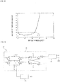
- Fig. 11 is a circuit diagram depicting an example of the driving circuit 21.
- the driving circuit 21 includes a voltage-controlled oscillator (VCO) 22, a driver circuit segment 23, and a current measurement circuit 24. Changing a control voltage applied to control terminals 22a of the VCO 22 causes the VCO 22 to transmit a predetermined voltage signal to the driver circuit segment 23.
- VCO voltage-controlled oscillator
- the driver circuit segment 23 drives the piezoelectric element 4 at the above sweep speed so as to sweep in a predetermined frequency range.
- the current measurement circuit 24 measures a current flowing through the piezoelectric element 4 and outputs a voltage in accordance with a value of the current.
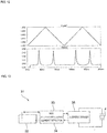
- the upper graph in Fig. 12 represents a voltage waveform that is input to the VCO 22.
- the lower graph in Fig. 12 represents a change in a current measured by the current measurement circuit 24.
- the driving voltage is continuously increased, for example, from 1.85 V to 1.90 V, and thereafter continuously decreased from 1.90 V to 1.85 V.
- the sweep is repeated by repeating the increase and decrease.
- the procedure of sweeping the frequency from the lower limit to the upper limit in the frequency sweep range preferably includes a step of increasing the sweep voltage and a step of decreasing the sweep voltage after the step of increasing the sweep voltage, and the increase and decrease in the sweep voltage are preferably performed in a continuous manner rather than in a stepwise manner.
- the input voltage to the VCO is preferably controlled so as to obtain a slope to form a triangular wave and is frequency modulated to drive the piezoelectric element 4.
- the peak height of the triangular wave determines the width of frequency variation of the VCO 22, and the center voltage of the triangular wave determines the center frequency of the CVO 22.
- a separately-excited oscillator circuit is formed and has the period of the triangular wave as a parameter in addition to the above parameters.
- a current in the piezoelectric element 4 is preferably monitored by using the current measurement circuit 24.
- Fixed parameters of the separately-excited oscillator circuit can be set by using the current signal because the current has the maximum at or around the maximum amount of displacement, which enables atomization. Accordingly, liquid drops are moved and atomized by using parameters optimized in accordance with the volume and the number of liquid drops.
- a circuit used for a vibration-device driving method according to the present invention is not limited, as depicted in Fig. 1 .
- FIG. 13 is a block diagram for depicting a driving circuit for a vibration device according to a second embodiment of the present invention.
- a driving circuit 31 includes a controller 32.
- the controller 32 is connected to a VCQ 33 and a current measurement circuit 34.
- the VCO 33 is connected to a H-bridge driver 35.
- the H-bridge driver 35 drives the piezoelectric element 4.
- a current flowing through the piezoelectric element 4 can be detected by using the current measurement circuit 34. The detected current value is supplied to the controller 32.
- the controller 32 includes a digital to analog (DA) converter and an analog to digital (AD) converter.
- the DA converter provides a voltage to control the VCO 33.
- the AD converter digitizes a current detected by the current measurement circuit 34. In this way, the driving circuit 31 including the controller 32 may be used.
- control can be performed by using a method in which a plurality of parameters are adjusted. For example, the following steps can be taken. 1) The frequency is swept in a wide frequency range to detect a peak current. 2) The piezoelectric element 4 is driven a plurality of times in a narrower frequency range around the center frequency at which the current peaks. 3) The first step is repeated, so that the center frequency is corrected. Repeating the above steps ensures atomization of liquid drops.
- Atomization is achieved by using the separately-excited oscillator circuit described above in the vibration device 1 according to the present embodiment. Consequently, the obstruction of the field of view due to a liquid film formed when a self-excited oscillator circuit is used is reduced or suppressed.
- a current may be measured by using the current measurement circuit 24, or a voltage may be monitored by using a feedback electrode.
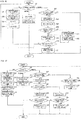
- Fig. 14 is a flowchart depicting a driving method according to a third embodiment as a whole. First, the initial settings are configured in step S1.
- Fig. 15 is a detailed flowchart of step S1, in which the initial settings are configured.
- parameter values are read from an internal memory in step S11A. It is determined in step S12A whether the parameter values in the internal memory are appropriate. If the parameter values are appropriate, initial values of the parameters are set to the parameter values recorded in the internal memory. If the internal memory is not appropriate, predetermined default values are adopted as the initial values of the parameters. Setting the initial values of the parameters completes the configuration of the initial settings.
- step S2 it is determined in step S2 whether a change in parameter values is requested. If a change is requested, parameter values are changed in step S4. Then, the status is set to a maximum current search state in step S5. Subsequently, the parameter values that have been changed are written to the internal memory in step S6. The process returns to step S2 again after step S6.
- step S2 If a change in parameter values is not requested in step S2, the maximum current search state or a sweep state is performed in accordance with the current status in step S7. The procedure for the maximum current search state is performed in step S8.
- Fig. 16 depicts a flowchart of the procedure for the maximum current search state.
- the process state is changed to a running state, a step width is calculated for a search voltage, adc_max is set to 0ct, and a timer is started in steps S21 to S24 in succession. If it is determined that the process state is the running state in step S7, it is determined in step S25 whether the timer reading has reached the end of a period. If the end of a period has been reached, the search voltage is output in step S26, an output voltage is read in step S27, and it is determined in step S28 whether the voltage that has been read is larger than adc_max.
- step S29 If the voltage that has been read is smaller than adc_max, the search voltage is increased in step S29. It is determined in step S30 whether the search voltage is equal to the maximum. If the search voltage is equal to the maximum, the process state is changed to the finished state in step S31. If the search voltage is not equal to the maximum, the process returns to step S7.
- adc_max is set in step S32 to the voltage that has been read. Then, the current search voltage is recorded in step S33.
- step S9 it is determined in step S9 whether the search for the maximum current is finished. If the search for the maximum current is finished, the status is set to the sweep state in step S10. If the search for the maximum current is not finished in step S9, the process returns to step S2.
- Fig. 17 depicts a flowchart of the procedure for the sweep state.
- a sweep voltage change timer is started to operate, and a sweep end timer is started in steps S42 to S44.
- a frequency sweep range is calculated by using the maximum current in step S45.
- a sweep voltage value is set to the minimum in the frequency sweep range in step S46. More specifically, the sweep voltage value is set to the value corresponding to the minimum in the frequency sweep range.
- step S47 If the current process state is the running state in step S41, it is determined in step S47 whether the reading of the sweep voltage change timer has reached the end of a period. If the end of a period has been reached, the sweep voltage value is output in step S48, and the voltage sweep direction in the next step is identified in step S49. If the voltage sweep direction is the direction in which the voltage is decreased, the sweep voltage value is decreased in step S50. Next, it is determined in step S51 whether the sweep voltage value is equal to the minimum in the frequency sweep range. If the sweep voltage value is equal to the minimum, the voltage sweep direction is changed to the upward direction in step S52.
- step S49 If the voltage sweep direction is the upward direction in step S49, the sweep voltage value is increased in step S53. Next, it is determined in step S54 whether the sweep voltage value is equal to the maximum in the frequency sweep range. If the sweep voltage value is equal to the maximum, the voltage sweep direction is changed to the downward direction in step S55. If the sweep voltage value is not equal to the maximum, the process is finished.
- step S56 If the reading of the sweep voltage change timer has not reached the end of a period in step S47, it is determined in step S56 whether the reading of the sweep end timer has reached the end of a period. If the end of a period has been reached, the process state is changed to the finished state in step S57, and the process is finished. If the reading of the sweep end timer has not reached the end of a period in step S56, the process returns to step S41.
- step S41 If the current process state is the finished state in step S41, the sweep voltage change timer is stopped, and the process state is changed to the initial state in steps S58 and S59. Then, the process is finished.
- step S12 it is determined in step S12 whether the sweep is finished. If the sweep is finished, the status is set to the maximum current search state in step S13. If the sweep is not finished, the process returns to step S2.
Description
- The present invention relates to a method of driving a vibration device having a function of removing liquid drops, such as water drops, and relates to the vibration device.
-
Patent Document 1 mentioned below discloses a camera having a function of removing raindrops. In this camera, a translucent or transparent dome-shaped cover is disposed in front of a camera body. A hollow cylinder is connected to the dome-shaped cover, and a piezoelectric ceramics vibrator is fixed to the hollow cylinder. When water drops, such as raindrops, have stuck to the dome-shaped cover, the piezoelectric vibrator vibrates the hollow cylinder and the dome-shaped cover. The vibration atomizes and removes water drops. When water drops are removed, vibration at or around the resonant frequency of the dome-shaped cover can efficiently remove water drops. - In
Patent Document 1, when the piezoelectric vibrator is driven, the frequency of an alternating current voltage is increased to the maximum frequency and then swept around resonant frequencies while the frequency is being decreased.Patent Document 1 discloses Pattern A in which the frequency is swept with a sawtooth waveform and Pattern B in which the frequency is increased to the maximum frequency and then swept around a plurality of resonant frequencies in descending order of frequency while the frequency is being decreased. - Patent Document 1:
Japanese Unexamined Patent Application Publication No. 2012-138768 - Further prior art related to removing liquid drops from a light transmitting body using a vibration device can be found in patent documents
US 2012/0243093 A1 ,JP H02-95947 US 2016/0266379 . - The driving method described in
Patent Document 1 has limits to the sweep range in which the frequency is swept. If an amplitude minimum exists even at the frequency lower limit, water drops or the like may remain. Accordingly, the frequency is repeatedly swept to obtain a sawtoothlike change in Pattern A, and the sweep range is widened by using a plurality of resonance points in Pattern B. - However, water drops sometimes spread in the form of a liquid film and obstructs the field of view of the camera during a process of vibrating the dome-shaped cover to remove water drops.
- An object of the present invention is to provide a method of driving a vibration device and to provide a vibration device. The method and the device are unlikely to cause obstruction of the field of view due to a spreading liquid film while liquid drops sticking to a light-transmitting body are removed.
- The present invention provides a method of driving a vibration device having a light-transmitting body and a piezoelectric element connected to the light-transmitting body so as to vibrate the light-transmitting body. The method is configured to atomize and remove liquid drops sticking to the light-transmitting body. A driving voltage for vibrating the piezoelectric element is swept at a sweep speed in a range of 1 Hz to 50 Hz so as to sweep a vibration frequency of the piezoelectric element to cover a frequency range including both of a resonant frequency of the light-transmitting body without liquid drops sticking to the light-transmitting body and a resonant frequency of the light-transmitting body with the liquid drops sticking to the light-transmitting body.
- In a specific aspect of the method of driving a vibration device according to the present invention, a procedure of sweeping in the frequency range includes a step of increasing a sweep voltage and a step of decreasing the sweep voltage after the step of increasing the sweep voltage, and an increase and a decrease in the sweep voltage are performed in a continuous manner.
- In another specific aspect of the method of driving a vibration device according to the present invention, a first step in which the piezoelectric element is driven so as to atomize liquid drops sticking to the light-transmitting body, a second step in which the light-transmitting body is caused to vibrate more weakly than in the first step or caused to stop vibrating, and a third step, which follows the second step, to atomize liquid drops sticking to the light-transmitting body are performed by a sweep in the frequency range.
- A vibration device according to the present invention includes a light-transmitting body, a piezoelectric element that is connected to the light-transmitting body and that vibrates the light-transmitting body, and a control circuit that is electrically connected to the piezoelectric element and that sweeps at a speed in a range of 1 Hz to 50 Hz a driving voltage for vibrating the piezoelectric element so as to sweep a vibration frequency of the piezoelectric element to cover a frequency range including a resonant frequency of the light-transmitting body and a resonant frequency of the light-transmitting body with liquid drops sticking to the light-transmitting body.
- In a specific aspect of the vibration device according to the present invention, the vibration device further includes a hollow cylindrical body connecting the light-transmitting body to the piezoelectric element. The piezoelectric element has a ringlike form. The piezoelectric element having a ringlike form is fixed to one end of the hollow cylindrical body, and the light-transmitting body is fixed to the other end of the hollow cylindrical body.
- According to the vibration-device driving method and the vibration device of the present invention, while liquid drops sticking to a light-transmitting body are atomized and removed, a liquid film is unlikely to spread on the surface of the light-transmitting body. Thus, when the light-transmitting body is used for the cover or the like of a camera, obstruction of the field of view is unlikely to occur.
-
- [
Fig. 1] Fig. 1 is a simplified front elevational cross-sectional view of a vibration device according to a first embodiment of the present invention. - [
Fig. 2] Fig. 2 is an exploded perspective view depicting a vibrating portion of the vibration device according to the present invention. - [
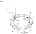
Fig. 3] Fig. 3 is a perspective view for depicting a piezoelectric element used in the vibration device according to the first embodiment. - [
Fig. 4] Fig. 4 (a) to Fig. 4 (c) are schematic front elevational cross-sectional views for depicting a procedure of removing water drops in the related art. - [
Fig. 5] Fig. 5 (a) to Fig. 5 (d) are schematic front elevational cross-sectional views for depicting a procedure of atomizing liquid drops in a vibration-device driving method according to an embodiment of the present invention. - [
Fig. 6] Fig. 6 (a) and Fig. 6 (b) depict a change in an amount of displacement of a light-transmitting body when sweep speeds are 1 Hz and 5 Hz, respectively. - [
Fig. 7] Fig. 7 (a) and Fig. 7 (b) depict a change in an amount of displacement of the light-transmitting body when the sweep speeds are 10Hz and 20Hz, respectively. - [
Fig. 8] Fig. 8 depicts a change in an amount of displacement of the light-transmitting body when the sweep speed is 100Hz. - [
Fig. 9] Fig. 9 depicts resonance characteristics of the light-transmitting body with and without liquid drops sticking to the light-transmitting body. - [
Fig. 10] Fig. 10 depicts a relationship between the sweep frequency and an amount of time used for atomization. - [
Fig. 11] Fig. 11 is a circuit diagram depicting a vibration-device driving circuit according to the first embodiment of the present invention. - [
Fig. 12] Fig. 12 depicts a waveform of a driving voltage that is input to a voltage-controlled oscillator (VCO) and a waveform of a magnetic force current applied to the piezoelectric element. - [
Fig. 13] Fig. 13 is a block diagram for depicting a vibration-device driving circuit according to a second embodiment of the present invention. - [
Fig. 14] Fig. 14 is a flowchart depicting a method of controlling a driving voltage by using a controller. - [
Fig. 15] Fig. 15 is a detailed flowchart of a procedure of configuring the initial settings in the flowchart depicted inFig. 14 . - [
Fig. 16] Fig. 16 is a flowchart of a procedure of searching the maximum current in the flowchart depicted inFig. 14 . - [
Fig. 17] Fig. 17 is a flowchart of a sweep procedure in the flowchart depicted inFig. 14 . - Hereinafter, specific embodiments of the present invention will be described with reference to the drawings, and the present invention will be disclosed.
- It is to be noted that the embodiments are described in the specification for illustrative purposes and that partial substitutions or combinations of configurations are feasible in different embodiments.
-
Fig. 1 is a simplified front elevational cross-sectional view for depicting a vibration device according to a first embodiment of the present invention, andFig. 2 is an exploded perspective view depicting a vibrating portion of the vibration device. - A
vibration device 1 includes a light-transmittingbody 2 that is translucent or transparent, a hollowcylindrical body 3, and apiezoelectric element 4. The hollowcylindrical body 3 is hollow and has a substantially cylindrical form. The light-transmittingbody 2, which has a platelike form, is fixed to the hollowcylindrical body 3 so as to close an opening at one end of the hollowcylindrical body 3. The light-transmittingbody 2 is made of a translucent or transparent material, such as resin or glass. The light-transmittingbody 2 is preferably transparent. - The light-transmitting
body 2 is fixed to the hollowcylindrical body 3 with abonding agent layer 5 interposed therebetween. - The
piezoelectric element 4 has a ringlike form. Thepiezoelectric element 4 includes a ring-shapedpiezoelectric member 6. The ring-shapedpiezoelectric member 6 is made of piezoelectric ceramics and has been subjected to poling treatment in the thickness direction. Afirst electrode 7 is disposed on one surface of the ring-shapedpiezoelectric member 6, and asecond electrode 8 is disposed on the other surface. - As depicted in
Fig. 3 , thefirst electrode 7 hascutouts cutouts piezoelectric member 6. Anelectrode 10a, which is independent of thefirst electrode 7, is disposed inside thecutout 7a. Theelectrode 10a serves as a feedback electrode to monitor a voltage generated by a piezoelectric effect during vibration. Anelectrode 10b is disposed inside thecutout 7b. Theelectrode 10b is electrically connected to thesecond electrode 8 via a portion of the inner perimeter of the ring-shapedpiezoelectric member 6. An electrode section 7c is a portion of thefirst electrode 7, and an alternating current voltage is applied between theelectrode 10b and the electrode section 7c to excite vibration. If a current measurement circuit described below is unnecessary, theelectrode 10a, which serves as a feedback electrode, may be omitted. - Applying an alternating current voltage between the
first electrode 7 and thesecond electrode 8 causes thepiezoelectric element 4 to vibrate. The vibration of thepiezoelectric element 4 propagates to the hollowcylindrical body 3, and the light-transmittingbody 2 vibrates together with the hollowcylindrical body 3. - If a liquid drop, such as a water drop, sticks to the light-transmitting
body 2, the vibration can move the water drop and remove the water drop by atomization. -
Fig. 4 (a) to Fig. 4 (c) are schematic front elevational cross-sectional views for depicting a procedure of removing water drops by using such a known vibration device as is disclosed inPatent Document 1. -
Fig. 4 (a) represents a state in which aliquid drop 1002 sticks on a light-transmittingbody 1001. When the light-transmittingbody 1001 is vibrated in this state in a known vibration device, the light-transmittingbody 1001 is vibrated at or around a resonant frequency. Consequently, as depicted inFig. 4 (b) ,droplets liquid drop 1002, and a portion of theliquid drop 1002 is removed. In this case, since theliquid drop 1002 is subjected to vibration, the surface tension of theliquid drop 1002 is reduced on the surface of the light-transmittingbody 1001, and theliquid drop 1002 spreads in the form of a liquid film. If vibration used for atomization continues to be applied, as depicted inFig. 4 (c) , theliquid drop 1002 spreads in the form of a liquid film. If further vibration is applied, theliquid drop 1002 can be removed by atomization. However, as depicted inFig. 4 (c) , theliquid drop 1002 sticks and spreads in the form of a liquid film during the atomization procedure. Thus, an issue of obstructing the field of view of the camera arises. - In a driving method according to the first embodiment of the present invention, a first step, a second step, and a third step below are performed to sweep a driving voltage described below.
-
Fig. 5 (a) to Fig. 5 (d) are schematic front elevational cross-sectional views depicting a procedure of removing liquid drops by the driving method according to the first embodiment of the present invention. - As depicted in
Fig. 5 (a) , aliquid drop 11 sticks on the light-transmittingbody 2. Next, the vibration device is driven as the first step. As depicted inFig. 5 (b) , theliquid drop 11 spreads and a portion of theliquid drop 11 is removed in the form ofdroplets - In the driving method according to the present embodiment, the driving voltage is swept to atomize and remove liquid drops at a sweep speed in the range of 1 Hz to 50 Hz so as to cover a frequency range including both of the resonant frequency of the light-transmitting body without liquid drops sticking to the light-transmitting
body 2 and the resonant frequency of the light-transmitting body with liquid drops sticking to the light-transmittingbody 2. Since the driving voltage is swept in this way, the second step in which the light-transmittingbody 2 vibrates more weakly than in the first step is performed after the first step. In the second step, as depicted inFig. 5 (c) , theliquid drop 11, a portion of which has been atomized and whose volume has been reduced, is restored to a spherical form because of the surface tension and has a certain thickness again on the surface of the light-transmittingbody 2. In the second step, the light-transmittingbody 2 is caused to vibrate more weakly than in the first step, which means that the light-transmittingbody 2 is caused to vibrate in a manner such that the amplitude and the intensity of vibration of the light-transmittingbody 2 are reduced. Alternatively, the vibration of the light-transmittingbody 2 may be stopped in the second step. - Subsequently, the light-transmitting
body 2 is caused to vibrate more strongly in the third step than in the second step. Namely, further continuation of the sweep advances atomization, as depicted inFig. 5 (d) . Thus, theliquid drop 11 is removed in the end. - Thus, as depicted in
Fig. 5 (c) , according to the vibration-device driving method in the present embodiment, theliquid drop 11 is unlikely to stick to the light-transmittingbody 2 in the form of a liquid film during the procedure of atomization. Thus, obstruction of the field of view of the camera is unlikely to occur. - As described above, the vibration-device driving method according to the present embodiment has a feature of sweeping in the above frequency range at a sweep speed in the range of 1 Hz to 50 Hz. This feature will be described with reference to
Fig. 6 (a), Fig. 6 (b) ,Fig. 7 (a), Fig. 7 (b) , andFig. 8 . -
Fig. 6 (a), Fig. 6 (b) ,Fig. 7 (a), Fig. 7 (b) , andFig. 8 depict a temporal change in a displacement signal, which is equivalent to the amount of displacement of the light-transmittingbody 2, at sweep speeds of 1 Hz, 5 Hz, 10 Hz, 20 Hz, and 100 Hz, respectively. - As depicted in
Figs. 6 to 8 , a sufficient amount of displacement can be obtained at sweep speeds of 1 Hz and 5 Hz, and a distinct peak of displacement appears. - In contrast, as the sweep speed increases, the amount of displacement decreases. As depicted in
Fig. 8 , the frequency at which the maximum amplitude appears changes at 100 Hz, and it can be seen that next resonance appears before liquid drops are restored to original forms. - Similarly to
Figs. 6 to 8 above, the sweep speed is varied, and the amount of time used for atomization is obtained. The horizontal axis inFig. 10 represents a frequency, which is equivalent to a sweep speed, and the vertical axis represents the amount of time used to remove a water drop having a volume of 5 µl as a liquid drop. - As is evident from
Fig. 10 , if the sweep speed, which is equivalent to the sweep frequency, exceeds 50 Hz, the amount of time used for atomization rapidly increases. In addition,Fig. 10 indicates that the amount of time used for atomization is equal to 10 seconds or shorter and water drops can efficiently be atomized if the sweep frequency is in the range of 1 Hz to 50 Hz. -
Fig. 9 depicts resonance characteristics of the light-transmittingbody 2 with and without liquid drops sticking to the light-transmittingbody 2. As depicted inFig. 9 , the resonant frequencies of the light-transmittingbody 2 with and without sticking liquid drops are different. - Thus, in the present embodiment, the driving voltage is swept to vibrate the
piezoelectric element 4 at a sweep speed in the range of 1 Hz to 50 Hz as described above so as to cover a frequency range including both of the resonant frequency of the light-transmittingbody 2 without liquid drops sticking to the light-transmittingbody 2 and the resonant frequency of the light-transmittingbody 2 with liquid drops sticking to the light-transmittingbody 2. In this way, liquid drops can quickly be atomized as described above. - The vibration device is driven as described above, and the atomization procedure is performed in three steps. In the first step, the piezoelectric element is driven so as to atomize liquid drops sticking to the light-transmitting body. In the second step, the light-transmitting
body 2 is caused to vibrate more weakly than in the first step or caused to stop vibrating. In the third step, which follows the second step, the light-transmittingbody 2 is caused to vibrate more strongly than in the second step, and liquid drops sticking to the light-transmittingbody 2 are atomized again. Accordingly, as depicted inFig. 5 (c) above, liquid drops are unlikely to spread in the form of a liquid film on the surface of the light-transmittingbody 2 in the second step, and the field of view or the like of the camera is also unlikely to be obstructed. - The
vibration device 1 depicted inFig. 1 includes a drivingcircuit 21 to achieve the driving method described above. -
Fig. 11 is a circuit diagram depicting an example of the drivingcircuit 21. The drivingcircuit 21 includes a voltage-controlled oscillator (VCO) 22, adriver circuit segment 23, and acurrent measurement circuit 24. Changing a control voltage applied to controlterminals 22a of theVCO 22 causes theVCO 22 to transmit a predetermined voltage signal to thedriver circuit segment 23. - The
driver circuit segment 23 drives thepiezoelectric element 4 at the above sweep speed so as to sweep in a predetermined frequency range. Thecurrent measurement circuit 24 measures a current flowing through thepiezoelectric element 4 and outputs a voltage in accordance with a value of the current. - The upper graph in
Fig. 12 represents a voltage waveform that is input to theVCO 22. The lower graph inFig. 12 represents a change in a current measured by thecurrent measurement circuit 24. - Although a current value is measured by the current measurement circuit, a voltage to which the current value is converted is presented in the lower portion of
Fig. 12 . - As depicted in
Fig. 12 , the driving voltage is continuously increased, for example, from 1.85 V to 1.90 V, and thereafter continuously decreased from 1.90 V to 1.85 V. The sweep is repeated by repeating the increase and decrease. - As depicted in
Fig. 12 , in the present invention, the procedure of sweeping the frequency from the lower limit to the upper limit in the frequency sweep range preferably includes a step of increasing the sweep voltage and a step of decreasing the sweep voltage after the step of increasing the sweep voltage, and the increase and decrease in the sweep voltage are preferably performed in a continuous manner rather than in a stepwise manner. In this case, since the change in voltage is gradual, and ringing is unlikely to occur. Accordingly, the efficiency of vibration used for atomization can be enhanced. In other words, as depicted in the upper portion ofFig. 12 , the input voltage to the VCO is preferably controlled so as to obtain a slope to form a triangular wave and is frequency modulated to drive thepiezoelectric element 4. - The peak height of the triangular wave determines the width of frequency variation of the
VCO 22, and the center voltage of the triangular wave determines the center frequency of theCVO 22. A separately-excited oscillator circuit is formed and has the period of the triangular wave as a parameter in addition to the above parameters. - A current in the
piezoelectric element 4 is preferably monitored by using thecurrent measurement circuit 24. Fixed parameters of the separately-excited oscillator circuit can be set by using the current signal because the current has the maximum at or around the maximum amount of displacement, which enables atomization. Accordingly, liquid drops are moved and atomized by using parameters optimized in accordance with the volume and the number of liquid drops. - A circuit used for a vibration-device driving method according to the present invention is not limited, as depicted in
Fig. 1 . -
Fig. 13 is a block diagram for depicting a driving circuit for a vibration device according to a second embodiment of the present invention. A drivingcircuit 31 includes acontroller 32. Thecontroller 32 is connected to aVCQ 33 and acurrent measurement circuit 34. Similarly to the circuit depicted inFig. 11 , theVCO 33 is connected to a H-bridge driver 35. The H-bridge driver 35 drives thepiezoelectric element 4. A current flowing through thepiezoelectric element 4 can be detected by using thecurrent measurement circuit 34. The detected current value is supplied to thecontroller 32. - The
controller 32 includes a digital to analog (DA) converter and an analog to digital (AD) converter. The DA converter provides a voltage to control theVCO 33. The AD converter digitizes a current detected by thecurrent measurement circuit 34. In this way, the drivingcircuit 31 including thecontroller 32 may be used. - If the
controller 32 of this type is used, control can be performed by using a method in which a plurality of parameters are adjusted. For example, the following steps can be taken. 1) The frequency is swept in a wide frequency range to detect a peak current. 2) Thepiezoelectric element 4 is driven a plurality of times in a narrower frequency range around the center frequency at which the current peaks. 3) The first step is repeated, so that the center frequency is corrected. Repeating the above steps ensures atomization of liquid drops. - Atomization is achieved by using the separately-excited oscillator circuit described above in the
vibration device 1 according to the present embodiment. Consequently, the obstruction of the field of view due to a liquid film formed when a self-excited oscillator circuit is used is reduced or suppressed. - A current may be measured by using the
current measurement circuit 24, or a voltage may be monitored by using a feedback electrode. - An example control method in which a control circuit is used for control in one of the vibration-device driving methods according to the present invention will be described with reference to
Figs. 14 to 17 . -
Fig. 14 is a flowchart depicting a driving method according to a third embodiment as a whole. First, the initial settings are configured in step S1. -
Fig. 15 is a detailed flowchart of step S1, in which the initial settings are configured. As depicted inFig. 15 , parameter values are read from an internal memory in step S11A. It is determined in step S12A whether the parameter values in the internal memory are appropriate. If the parameter values are appropriate, initial values of the parameters are set to the parameter values recorded in the internal memory. If the internal memory is not appropriate, predetermined default values are adopted as the initial values of the parameters. Setting the initial values of the parameters completes the configuration of the initial settings. - Next, as depicted in
Fig. 14 , it is determined in step S2 whether a change in parameter values is requested. If a change is requested, parameter values are changed in step S4. Then, the status is set to a maximum current search state in step S5. Subsequently, the parameter values that have been changed are written to the internal memory in step S6. The process returns to step S2 again after step S6. - If a change in parameter values is not requested in step S2, the maximum current search state or a sweep state is performed in accordance with the current status in step S7. The procedure for the maximum current search state is performed in step S8.
-
Fig. 16 depicts a flowchart of the procedure for the maximum current search state. First, the process state is changed to a running state, a step width is calculated for a search voltage, adc_max is set to 0ct, and a timer is started in steps S21 to S24 in succession. If it is determined that the process state is the running state in step S7, it is determined in step S25 whether the timer reading has reached the end of a period. If the end of a period has been reached, the search voltage is output in step S26, an output voltage is read in step S27, and it is determined in step S28 whether the voltage that has been read is larger than adc_max. If the voltage that has been read is smaller than adc_max, the search voltage is increased in step S29. It is determined in step S30 whether the search voltage is equal to the maximum. If the search voltage is equal to the maximum, the process state is changed to the finished state in step S31. If the search voltage is not equal to the maximum, the process returns to step S7. - In contrast, if the voltage that has been read is larger than adc_max in step S28, adc_max is set in step S32 to the voltage that has been read. Then, the current search voltage is recorded in step S33.
- Referring back to
Fig. 14 , it is determined in step S9 whether the search for the maximum current is finished. If the search for the maximum current is finished, the status is set to the sweep state in step S10. If the search for the maximum current is not finished in step S9, the process returns to step S2. - If the current status is the sweep state in step S7, the procedure for the sweep state is performed in step S11.
Fig. 17 depicts a flowchart of the procedure for the sweep state. - As depicted in
Fig. 17 , if the current process state is the initial state in step S41, the process state is changed to the running state, a sweep voltage change timer is started to operate, and a sweep end timer is started in steps S42 to S44. A frequency sweep range is calculated by using the maximum current in step S45. A sweep voltage value is set to the minimum in the frequency sweep range in step S46. More specifically, the sweep voltage value is set to the value corresponding to the minimum in the frequency sweep range. - If the current process state is the running state in step S41, it is determined in step S47 whether the reading of the sweep voltage change timer has reached the end of a period. If the end of a period has been reached, the sweep voltage value is output in step S48, and the voltage sweep direction in the next step is identified in step S49. If the voltage sweep direction is the direction in which the voltage is decreased, the sweep voltage value is decreased in step S50. Next, it is determined in step S51 whether the sweep voltage value is equal to the minimum in the frequency sweep range. If the sweep voltage value is equal to the minimum, the voltage sweep direction is changed to the upward direction in step S52.
- If the voltage sweep direction is the upward direction in step S49, the sweep voltage value is increased in step S53. Next, it is determined in step S54 whether the sweep voltage value is equal to the maximum in the frequency sweep range. If the sweep voltage value is equal to the maximum, the voltage sweep direction is changed to the downward direction in step S55. If the sweep voltage value is not equal to the maximum, the process is finished.
- If the reading of the sweep voltage change timer has not reached the end of a period in step S47, it is determined in step S56 whether the reading of the sweep end timer has reached the end of a period. If the end of a period has been reached, the process state is changed to the finished state in step S57, and the process is finished. If the reading of the sweep end timer has not reached the end of a period in step S56, the process returns to step S41.
- If the current process state is the finished state in step S41, the sweep voltage change timer is stopped, and the process state is changed to the initial state in steps S58 and S59. Then, the process is finished.
- Referring back to
Fig. 14 , the procedure for the sweep state is performed in step S11. Then, it is determined in step S12 whether the sweep is finished. If the sweep is finished, the status is set to the maximum current search state in step S13. If the sweep is not finished, the process returns to step S2. - The control method described with reference to
Figs. 14 to 17 is only an example control method using the controller in the driving methods according to the present invention. Reference Signs List -
- 1 vibration device
- 2 light-transmitting body
- 3 hollow cylindrical body
- 4 piezoelectric element
- 5 bonding agent layer
- 6 piezoelectric member
- 7, 8 first and second electrodes
- 7a, 7b cutout
- 7c electrode section
- 9 terminal electrode
- 10a feedback electrode
- 10b electrode for connecting to the second electrode
- 11 liquid drop
- 11a droplets
- 21 driving circuit
- 22, 33 VCO
- 22a control terminal
- 23 driver circuit segment
- 24, 34 current measurement circuit
- 31 driving circuit
- 32 controller
- 35 H-bridge driver
Claims (5)
- A method of driving a vibration device having a light-transmitting body and a piezoelectric element connected to the light-transmitting body so as to vibrate the light-transmitting body, the method being configured to atomize and remove liquid drops sticking to the light-transmitting body,
wherein a driving voltage for vibrating the piezoelectric element is swept at a sweep speed in a range of 1 Hz to 50 Hz so as to sweep a vibration frequency of the piezoelectric element to cover a frequency range including both of a resonant frequency of the light-transmitting body without liquid drops sticking to the light-transmitting body and a resonant frequency of the light-transmitting body with the liquid drops sticking to the light-transmitting body. - The method of driving a vibration device according to Claim 1,
wherein a procedure of sweeping in the frequency range includes a step of increasing a sweep voltage and a step of decreasing the sweep voltage after the step of increasing the sweep voltage, and an increase and a decrease in the sweep voltage are performed in a continuous manner. - The method of driving a vibration device according to Claim 1 or Claim 2,wherein a first step in which the piezoelectric element is driven so as to atomize liquid drops sticking to the light-transmitting body,a second step in which the light-transmitting body is caused to vibrate more weakly than in the first step or caused to stop vibrating, anda third step, which follows the second step, to atomize liquid drops sticking to the light-transmitting bodyare performed by a sweep in the frequency range.
- A vibration device comprising:a light-transmitting body;a piezoelectric element that is connected to the light-transmitting body and that vibrates the light-transmitting body; anda control circuit that is electrically connected to the piezoelectric element and that sweeps at a speed in a range of 1 Hz to 50 Hz a driving voltage for vibrating the piezoelectric element so as to sweep a vibration frequency of the piezoelectric element to cover a frequency range including a resonant frequency of the light-transmitting body without liquid drops sticking to the light-transmitting bodyand a resonant frequency of the light-transmitting body with liquid drops sticking to the light-transmitting body.
- The vibration device according to Claim 4, further comprising:a hollow cylindrical body connecting the light-transmitting body to the piezoelectric element,wherein the piezoelectric element has a ringlike form, the piezoelectric element having a ringlike form is fixed to one end of the hollow cylindrical body, and the light-transmitting body is fixed to the other end of the hollow cylindrical body.
Applications Claiming Priority (2)
| Application Number | Priority Date | Filing Date | Title |
|---|---|---|---|
| JP2017154334 | 2017-08-09 | ||
| PCT/JP2018/015236 WO2019030982A1 (en) | 2017-08-09 | 2018-04-11 | Method for driving vibration device, and vibration device |
Publications (3)
| Publication Number | Publication Date |
|---|---|
| EP3606029A1 EP3606029A1 (en) | 2020-02-05 |
| EP3606029A4 EP3606029A4 (en) | 2020-12-16 |
| EP3606029B1 true EP3606029B1 (en) | 2021-12-15 |
Family
ID=65272820
Family Applications (1)
| Application Number | Title | Priority Date | Filing Date |
|---|---|---|---|
| EP18843656.2A Active EP3606029B1 (en) | 2017-08-09 | 2018-04-11 | Method for driving vibration device, and vibration device |
Country Status (5)
| Country | Link |
|---|---|
| US (1) | US10862405B2 (en) |
| EP (1) | EP3606029B1 (en) |
| JP (1) | JP6620914B2 (en) |
| CN (1) | CN110999272B (en) |
| WO (1) | WO2019030982A1 (en) |
Families Citing this family (9)
| Publication number | Priority date | Publication date | Assignee | Title |
|---|---|---|---|---|
| CN109076152B (en) * | 2016-06-24 | 2020-09-15 | 株式会社村田制作所 | Vibration device and imaging device |
| WO2018100796A1 (en) * | 2016-11-30 | 2018-06-07 | 株式会社村田製作所 | Vibration device, water droplet removal device for camera, and camera |
| CN113273169B (en) * | 2019-04-26 | 2023-06-06 | 株式会社村田制作所 | Cleaning device, imaging unit provided with cleaning device, and cleaning method |
| WO2021038942A1 (en) * | 2019-08-28 | 2021-03-04 | 株式会社村田製作所 | Vibration device and optical detection device |
| JP7283542B2 (en) * | 2020-03-19 | 2023-05-30 | 株式会社村田製作所 | Vibration device and vibration control method |
| CN113767616B (en) * | 2020-03-27 | 2023-04-04 | 株式会社村田制作所 | Vibration device and vibration control method |
| CN114206516B (en) * | 2020-04-30 | 2023-07-04 | 株式会社村田制作所 | Cleaning device, imaging unit provided with cleaning device, and cleaning method |
| US20220219381A1 (en) * | 2021-01-08 | 2022-07-14 | Xerox Corporation | Building an object with a three-dimensional printer using vibrational energy |
| JP2023058271A (en) * | 2021-10-13 | 2023-04-25 | i-PRO株式会社 | Monitoring camera |
Family Cites Families (12)
| Publication number | Priority date | Publication date | Assignee | Title |
|---|---|---|---|---|
| JPH0295947A (en) * | 1988-09-30 | 1990-04-06 | Aisin Seiki Co Ltd | Water drop removing device |
| JPH08183428A (en) * | 1995-01-06 | 1996-07-16 | Nippon Sheet Glass Co Ltd | Active type water repelling window system |
| CA2371873C (en) * | 1999-03-05 | 2006-06-20 | S.C. Johnson & Son, Inc. | Control system for atomizing liquids with a piezoelectric vibrator |
| JP5430367B2 (en) * | 2009-11-26 | 2014-02-26 | キヤノン株式会社 | Dust removing device and dust removing method |
| JP5693081B2 (en) * | 2010-08-06 | 2015-04-01 | キヤノン株式会社 | Vibration generating device, driving method thereof, foreign matter removing device, and optical device |
| JP2012138768A (en) * | 2010-12-27 | 2012-07-19 | Hitachi Kokusai Electric Inc | Dome type monitor camera system |
| US8899761B2 (en) * | 2011-03-23 | 2014-12-02 | Gentex Corporation | Lens cleaning apparatus |
| JP5948781B2 (en) * | 2011-10-05 | 2016-07-06 | アイシン精機株式会社 | Camera with water drop removal function |
| CN104069978A (en) * | 2013-03-25 | 2014-10-01 | 厦门市骏耀光电科技有限公司 | Ultrasonic atomization device and atomization method |
| US10401618B2 (en) * | 2015-03-11 | 2019-09-03 | Texas Instruments Incorporated | Ultrasonic lens cleaning system with current sensing |
| GB201510166D0 (en) * | 2015-06-11 | 2015-07-29 | The Technology Partnership Plc | Spray delivery device |
| JP2017085276A (en) * | 2015-10-26 | 2017-05-18 | オリンパス株式会社 | Droplet elimination device, image device having droplet elimination device, droplet elimination device control method, and droplet elimination device control program |
-
2018
- 2018-04-11 JP JP2019535587A patent/JP6620914B2/en active Active
- 2018-04-11 WO PCT/JP2018/015236 patent/WO2019030982A1/en unknown
- 2018-04-11 EP EP18843656.2A patent/EP3606029B1/en active Active
- 2018-04-11 CN CN201880051560.6A patent/CN110999272B/en active Active
-
2020
- 2020-01-03 US US16/733,258 patent/US10862405B2/en active Active
Also Published As
| Publication number | Publication date |
|---|---|
| EP3606029A4 (en) | 2020-12-16 |
| JP6620914B2 (en) | 2019-12-18 |
| US10862405B2 (en) | 2020-12-08 |
| CN110999272B (en) | 2021-05-14 |
| WO2019030982A1 (en) | 2019-02-14 |
| US20200144939A1 (en) | 2020-05-07 |
| EP3606029A1 (en) | 2020-02-05 |
| JPWO2019030982A1 (en) | 2019-12-26 |
| CN110999272A (en) | 2020-04-10 |
Similar Documents
| Publication | Publication Date | Title |
|---|---|---|
| EP3606029B1 (en) | Method for driving vibration device, and vibration device | |
| KR100366777B1 (en) | Method for driving piezoelectic transducer and driving circuit therefor | |
| CN204724386U (en) | There is the ultrasonic atomizer of controlled smog efferent | |
| JP6446501B2 (en) | Drive circuit for passive resonant circuit and transmitter device | |
| JPH09140168A (en) | Driver for oscillation motor | |
| US11770078B2 (en) | Vibration device and driving device | |
| KR20200100523A (en) | Ultrasonic cleaning device using ultrasonic vibrator and ultrasonic vibrator | |
| WO2020003574A1 (en) | Oscillation device and optical detection device | |
| JP7283542B2 (en) | Vibration device and vibration control method | |
| JP5192270B2 (en) | Method and apparatus for driving ultrasonic transducer | |
| FR2711284A1 (en) | Training apparatus and camera comprising it. | |
| JPH0479777A (en) | Driving circuit for ultrasonic motor | |
| US8471436B2 (en) | Piezoelectric element drive circuit and foreign substance removing apparatus | |
| US7244377B2 (en) | Acoustic enhancement of particle fabrication by spinning | |
| JPH0211435A (en) | Device for removing water droplet | |
| WO2024084743A1 (en) | Optical device and imaging unit provided with optical device | |
| JPH0295945A (en) | Water drop removing device | |
| KR20130014500A (en) | Microelectromechanical system with reduced speckle contrast | |
| JP2770542B2 (en) | US oscillator of transducer in wire bonder | |
| JPS6323776A (en) | Sieving device | |
| JPH0231960A (en) | Device for removing water drop | |
| JPH03235742A (en) | Water drop removing device on mirror for automobile | |
| JPH0429573A (en) | Driving circuit of ultrasonic motor | |
| JP2000324860A5 (en) | ||
| JPH01240340A (en) | Device for removing water drop |
Legal Events
| Date | Code | Title | Description |
|---|---|---|---|
| STAA | Information on the status of an ep patent application or granted ep patent |
Free format text: STATUS: THE INTERNATIONAL PUBLICATION HAS BEEN MADE |
|
| PUAI | Public reference made under article 153(3) epc to a published international application that has entered the european phase |
Free format text: ORIGINAL CODE: 0009012 |
|
| STAA | Information on the status of an ep patent application or granted ep patent |
Free format text: STATUS: REQUEST FOR EXAMINATION WAS MADE |
|
| 17P | Request for examination filed |
Effective date: 20191022 |
|
| AK | Designated contracting states |
Kind code of ref document: A1 Designated state(s): AL AT BE BG CH CY CZ DE DK EE ES FI FR GB GR HR HU IE IS IT LI LT LU LV MC MK MT NL NO PL PT RO RS SE SI SK SM TR |
|
| AX | Request for extension of the european patent |
Extension state: BA ME |
|
| DAV | Request for validation of the european patent (deleted) | ||
| DAX | Request for extension of the european patent (deleted) | ||
| A4 | Supplementary search report drawn up and despatched |
Effective date: 20201113 |
|
| RIC1 | Information provided on ipc code assigned before grant |
Ipc: G03B 17/56 20060101ALI20201109BHEP Ipc: H04N 7/18 20060101ALI20201109BHEP Ipc: G02B 27/00 20060101ALI20201109BHEP Ipc: H04N 5/225 20060101AFI20201109BHEP |
|
| GRAP | Despatch of communication of intention to grant a patent |
Free format text: ORIGINAL CODE: EPIDOSNIGR1 |
|
| STAA | Information on the status of an ep patent application or granted ep patent |
Free format text: STATUS: GRANT OF PATENT IS INTENDED |
|
| RIC1 | Information provided on ipc code assigned before grant |
Ipc: H04N 5/225 20060101AFI20210528BHEP Ipc: G03B 17/56 20210101ALI20210528BHEP Ipc: H04N 7/18 20060101ALI20210528BHEP Ipc: G02B 27/00 20060101ALI20210528BHEP Ipc: B08B 7/02 20060101ALI20210528BHEP Ipc: B08B 17/02 20060101ALI20210528BHEP |
|
| INTG | Intention to grant announced |
Effective date: 20210701 |
|
| GRAS | Grant fee paid |
Free format text: ORIGINAL CODE: EPIDOSNIGR3 |
|
| GRAA | (expected) grant |
Free format text: ORIGINAL CODE: 0009210 |
|
| STAA | Information on the status of an ep patent application or granted ep patent |
Free format text: STATUS: THE PATENT HAS BEEN GRANTED |
|
| AK | Designated contracting states |
Kind code of ref document: B1 Designated state(s): AL AT BE BG CH CY CZ DE DK EE ES FI FR GB GR HR HU IE IS IT LI LT LU LV MC MK MT NL NO PL PT RO RS SE SI SK SM TR |
|
| REG | Reference to a national code |
Ref country code: GB Ref legal event code: FG4D Ref country code: CH Ref legal event code: EP |
|
| REG | Reference to a national code |
Ref country code: IE Ref legal event code: FG4D Ref country code: DE Ref legal event code: R096 Ref document number: 602018028359 Country of ref document: DE |
|
| REG | Reference to a national code |
Ref country code: AT Ref legal event code: REF Ref document number: 1456348 Country of ref document: AT Kind code of ref document: T Effective date: 20220115 |
|
| REG | Reference to a national code |
Ref country code: LT Ref legal event code: MG9D |
|
| REG | Reference to a national code |
Ref country code: NL Ref legal event code: MP Effective date: 20211215 |
|
| PG25 | Lapsed in a contracting state [announced via postgrant information from national office to epo] |
Ref country code: RS Free format text: LAPSE BECAUSE OF FAILURE TO SUBMIT A TRANSLATION OF THE DESCRIPTION OR TO PAY THE FEE WITHIN THE PRESCRIBED TIME-LIMIT Effective date: 20211215 Ref country code: LT Free format text: LAPSE BECAUSE OF FAILURE TO SUBMIT A TRANSLATION OF THE DESCRIPTION OR TO PAY THE FEE WITHIN THE PRESCRIBED TIME-LIMIT Effective date: 20211215 Ref country code: FI Free format text: LAPSE BECAUSE OF FAILURE TO SUBMIT A TRANSLATION OF THE DESCRIPTION OR TO PAY THE FEE WITHIN THE PRESCRIBED TIME-LIMIT Effective date: 20211215 Ref country code: BG Free format text: LAPSE BECAUSE OF FAILURE TO SUBMIT A TRANSLATION OF THE DESCRIPTION OR TO PAY THE FEE WITHIN THE PRESCRIBED TIME-LIMIT Effective date: 20220315 |
|
| REG | Reference to a national code |
Ref country code: AT Ref legal event code: MK05 Ref document number: 1456348 Country of ref document: AT Kind code of ref document: T Effective date: 20211215 |
|
| PG25 | Lapsed in a contracting state [announced via postgrant information from national office to epo] |
Ref country code: SE Free format text: LAPSE BECAUSE OF FAILURE TO SUBMIT A TRANSLATION OF THE DESCRIPTION OR TO PAY THE FEE WITHIN THE PRESCRIBED TIME-LIMIT Effective date: 20211215 Ref country code: NO Free format text: LAPSE BECAUSE OF FAILURE TO SUBMIT A TRANSLATION OF THE DESCRIPTION OR TO PAY THE FEE WITHIN THE PRESCRIBED TIME-LIMIT Effective date: 20220315 Ref country code: LV Free format text: LAPSE BECAUSE OF FAILURE TO SUBMIT A TRANSLATION OF THE DESCRIPTION OR TO PAY THE FEE WITHIN THE PRESCRIBED TIME-LIMIT Effective date: 20211215 Ref country code: HR Free format text: LAPSE BECAUSE OF FAILURE TO SUBMIT A TRANSLATION OF THE DESCRIPTION OR TO PAY THE FEE WITHIN THE PRESCRIBED TIME-LIMIT Effective date: 20211215 Ref country code: GR Free format text: LAPSE BECAUSE OF FAILURE TO SUBMIT A TRANSLATION OF THE DESCRIPTION OR TO PAY THE FEE WITHIN THE PRESCRIBED TIME-LIMIT Effective date: 20220316 |
|
| PG25 | Lapsed in a contracting state [announced via postgrant information from national office to epo] |
Ref country code: NL Free format text: LAPSE BECAUSE OF FAILURE TO SUBMIT A TRANSLATION OF THE DESCRIPTION OR TO PAY THE FEE WITHIN THE PRESCRIBED TIME-LIMIT Effective date: 20211215 |
|
| PG25 | Lapsed in a contracting state [announced via postgrant information from national office to epo] |
Ref country code: SM Free format text: LAPSE BECAUSE OF FAILURE TO SUBMIT A TRANSLATION OF THE DESCRIPTION OR TO PAY THE FEE WITHIN THE PRESCRIBED TIME-LIMIT Effective date: 20211215 Ref country code: SK Free format text: LAPSE BECAUSE OF FAILURE TO SUBMIT A TRANSLATION OF THE DESCRIPTION OR TO PAY THE FEE WITHIN THE PRESCRIBED TIME-LIMIT Effective date: 20211215 Ref country code: RO Free format text: LAPSE BECAUSE OF FAILURE TO SUBMIT A TRANSLATION OF THE DESCRIPTION OR TO PAY THE FEE WITHIN THE PRESCRIBED TIME-LIMIT Effective date: 20211215 Ref country code: PT Free format text: LAPSE BECAUSE OF FAILURE TO SUBMIT A TRANSLATION OF THE DESCRIPTION OR TO PAY THE FEE WITHIN THE PRESCRIBED TIME-LIMIT Effective date: 20220418 Ref country code: ES Free format text: LAPSE BECAUSE OF FAILURE TO SUBMIT A TRANSLATION OF THE DESCRIPTION OR TO PAY THE FEE WITHIN THE PRESCRIBED TIME-LIMIT Effective date: 20211215 Ref country code: EE Free format text: LAPSE BECAUSE OF FAILURE TO SUBMIT A TRANSLATION OF THE DESCRIPTION OR TO PAY THE FEE WITHIN THE PRESCRIBED TIME-LIMIT Effective date: 20211215 Ref country code: CZ Free format text: LAPSE BECAUSE OF FAILURE TO SUBMIT A TRANSLATION OF THE DESCRIPTION OR TO PAY THE FEE WITHIN THE PRESCRIBED TIME-LIMIT Effective date: 20211215 |
|
| PG25 | Lapsed in a contracting state [announced via postgrant information from national office to epo] |
Ref country code: PL Free format text: LAPSE BECAUSE OF FAILURE TO SUBMIT A TRANSLATION OF THE DESCRIPTION OR TO PAY THE FEE WITHIN THE PRESCRIBED TIME-LIMIT Effective date: 20211215 Ref country code: AT Free format text: LAPSE BECAUSE OF FAILURE TO SUBMIT A TRANSLATION OF THE DESCRIPTION OR TO PAY THE FEE WITHIN THE PRESCRIBED TIME-LIMIT Effective date: 20211215 |
|
| REG | Reference to a national code |
Ref country code: DE Ref legal event code: R097 Ref document number: 602018028359 Country of ref document: DE |
|
| PG25 | Lapsed in a contracting state [announced via postgrant information from national office to epo] |
Ref country code: IS Free format text: LAPSE BECAUSE OF FAILURE TO SUBMIT A TRANSLATION OF THE DESCRIPTION OR TO PAY THE FEE WITHIN THE PRESCRIBED TIME-LIMIT Effective date: 20220415 |
|
| PLBE | No opposition filed within time limit |
Free format text: ORIGINAL CODE: 0009261 |
|
| STAA | Information on the status of an ep patent application or granted ep patent |
Free format text: STATUS: NO OPPOSITION FILED WITHIN TIME LIMIT |
|
| PG25 | Lapsed in a contracting state [announced via postgrant information from national office to epo] |
Ref country code: DK Free format text: LAPSE BECAUSE OF FAILURE TO SUBMIT A TRANSLATION OF THE DESCRIPTION OR TO PAY THE FEE WITHIN THE PRESCRIBED TIME-LIMIT Effective date: 20211215 Ref country code: AL Free format text: LAPSE BECAUSE OF FAILURE TO SUBMIT A TRANSLATION OF THE DESCRIPTION OR TO PAY THE FEE WITHIN THE PRESCRIBED TIME-LIMIT Effective date: 20211215 |
|
| 26N | No opposition filed |
Effective date: 20220916 |
|
| REG | Reference to a national code |
Ref country code: DE Ref legal event code: R079 Ref document number: 602018028359 Country of ref document: DE Free format text: PREVIOUS MAIN CLASS: H04N0005225000 Ipc: H04N0023000000 |
|
| PG25 | Lapsed in a contracting state [announced via postgrant information from national office to epo] |
Ref country code: SI Free format text: LAPSE BECAUSE OF FAILURE TO SUBMIT A TRANSLATION OF THE DESCRIPTION OR TO PAY THE FEE WITHIN THE PRESCRIBED TIME-LIMIT Effective date: 20211215 |
|
| REG | Reference to a national code |
Ref country code: CH Ref legal event code: PL |
|
| GBPC | Gb: european patent ceased through non-payment of renewal fee |
Effective date: 20220411 |
|
| REG | Reference to a national code |
Ref country code: BE Ref legal event code: MM Effective date: 20220430 |
|
| PG25 | Lapsed in a contracting state [announced via postgrant information from national office to epo] |
Ref country code: MC Free format text: LAPSE BECAUSE OF FAILURE TO SUBMIT A TRANSLATION OF THE DESCRIPTION OR TO PAY THE FEE WITHIN THE PRESCRIBED TIME-LIMIT Effective date: 20211215 Ref country code: LU Free format text: LAPSE BECAUSE OF NON-PAYMENT OF DUE FEES Effective date: 20220411 Ref country code: LI Free format text: LAPSE BECAUSE OF NON-PAYMENT OF DUE FEES Effective date: 20220430 Ref country code: GB Free format text: LAPSE BECAUSE OF NON-PAYMENT OF DUE FEES Effective date: 20220411 Ref country code: CH Free format text: LAPSE BECAUSE OF NON-PAYMENT OF DUE FEES Effective date: 20220430 |
|
| PG25 | Lapsed in a contracting state [announced via postgrant information from national office to epo] |
Ref country code: BE Free format text: LAPSE BECAUSE OF NON-PAYMENT OF DUE FEES Effective date: 20220430 |
|
| PG25 | Lapsed in a contracting state [announced via postgrant information from national office to epo] |
Ref country code: IE Free format text: LAPSE BECAUSE OF NON-PAYMENT OF DUE FEES Effective date: 20220411 |
|
| PG25 | Lapsed in a contracting state [announced via postgrant information from national office to epo] |
Ref country code: IT Free format text: LAPSE BECAUSE OF FAILURE TO SUBMIT A TRANSLATION OF THE DESCRIPTION OR TO PAY THE FEE WITHIN THE PRESCRIBED TIME-LIMIT Effective date: 20211215 |
|
| PGFP | Annual fee paid to national office [announced via postgrant information from national office to epo] |
Ref country code: FR Payment date: 20230424 Year of fee payment: 6 Ref country code: DE Payment date: 20230420 Year of fee payment: 6 |