WO2020003574A1 - Oscillation device and optical detection device - Google Patents
Oscillation device and optical detection device Download PDFInfo
- Publication number
- WO2020003574A1 WO2020003574A1 PCT/JP2019/002548 JP2019002548W WO2020003574A1 WO 2020003574 A1 WO2020003574 A1 WO 2020003574A1 JP 2019002548 W JP2019002548 W JP 2019002548W WO 2020003574 A1 WO2020003574 A1 WO 2020003574A1
- Authority
- WO
- WIPO (PCT)
- Prior art keywords
- vibration
- light transmitting
- vibrating
- transmitting body
- vibrating body
- Prior art date
Links
Images


Classifications
-
- G—PHYSICS
- G03—PHOTOGRAPHY; CINEMATOGRAPHY; ANALOGOUS TECHNIQUES USING WAVES OTHER THAN OPTICAL WAVES; ELECTROGRAPHY; HOLOGRAPHY
- G03B—APPARATUS OR ARRANGEMENTS FOR TAKING PHOTOGRAPHS OR FOR PROJECTING OR VIEWING THEM; APPARATUS OR ARRANGEMENTS EMPLOYING ANALOGOUS TECHNIQUES USING WAVES OTHER THAN OPTICAL WAVES; ACCESSORIES THEREFOR
- G03B15/00—Special procedures for taking photographs; Apparatus therefor
-
- G—PHYSICS
- G03—PHOTOGRAPHY; CINEMATOGRAPHY; ANALOGOUS TECHNIQUES USING WAVES OTHER THAN OPTICAL WAVES; ELECTROGRAPHY; HOLOGRAPHY
- G03B—APPARATUS OR ARRANGEMENTS FOR TAKING PHOTOGRAPHS OR FOR PROJECTING OR VIEWING THEM; APPARATUS OR ARRANGEMENTS EMPLOYING ANALOGOUS TECHNIQUES USING WAVES OTHER THAN OPTICAL WAVES; ACCESSORIES THEREFOR
- G03B17/00—Details of cameras or camera bodies; Accessories therefor
- G03B17/02—Bodies
-
- G—PHYSICS
- G03—PHOTOGRAPHY; CINEMATOGRAPHY; ANALOGOUS TECHNIQUES USING WAVES OTHER THAN OPTICAL WAVES; ELECTROGRAPHY; HOLOGRAPHY
- G03B—APPARATUS OR ARRANGEMENTS FOR TAKING PHOTOGRAPHS OR FOR PROJECTING OR VIEWING THEM; APPARATUS OR ARRANGEMENTS EMPLOYING ANALOGOUS TECHNIQUES USING WAVES OTHER THAN OPTICAL WAVES; ACCESSORIES THEREFOR
- G03B17/00—Details of cameras or camera bodies; Accessories therefor
- G03B17/56—Accessories
-
- H—ELECTRICITY
- H04—ELECTRIC COMMUNICATION TECHNIQUE
- H04N—PICTORIAL COMMUNICATION, e.g. TELEVISION
- H04N23/00—Cameras or camera modules comprising electronic image sensors; Control thereof
Definitions
- the present invention relates to a vibration device and an optical detection device capable of removing water droplets and the like by mechanical vibration.
- Patent Literature 1 discloses a vibration device having a light-transmitting portion disposed in front of a camera body. In this vibrating device, water droplets adhering to the light transmitting portion are atomized by vibrating the light transmitting portion largely. Patent Literature 1 describes that a water droplet can be moved to a hydrophilic portion side by forming a hydrophilic portion other than a region to be photographed.
- antinodes of vibration and nodes of vibration are formed in a portion of the translucent portion located in the visual field region of the camera body.
- the water droplet moves toward the antinode of the vibration, and the water droplet is atomized near the antinode of the vibration.
- the water droplet located at the node of the vibration is hard to move toward the antinode of the vibration. For this reason, water droplets may remain and the field of view of the camera body may be obstructed.
- An object of the present invention is to provide a vibration device and an optical detection device that can more reliably secure a detection area of an optical detection element.
- a vibration device includes a light-transmitting member disposed so as to include at least a part of a detection region of an optical detection element, and a vibration device disposed such that an optical axis of the light-transmitting member is inclined from a vertical direction. And a vibrating element having a vibrating body directly or indirectly connected to the translucent body, wherein the hydrophilic film is provided at least in a portion including the detection region in the translucent body.
- a control unit electrically connected to the vibrating element, wherein the control unit controls the vibration in a first control mode in which the vibrating element alternately switches between vibration and rest.
- the optical detection device includes a vibration device configured according to the present invention, and an optical detection element arranged so that the light transmitting body includes a detection region.
- FIG. 1 is a schematic perspective view of an imaging device having a vibration device according to the first embodiment of the present invention.
- FIG. 2 is a schematic front sectional view of an imaging device having the vibration device according to the first embodiment of the present invention.
- FIG. 3 is a schematic perspective view of the piezoelectric vibrator according to the first embodiment of the present invention.
- FIG. 4 is a schematic diagram for explaining each vibration mode.
- FIG. 5 is a diagram showing a relationship between the excitation frequency f of the capillary wave and the wavelength ⁇ .
- FIGS. 6A to 6D show a vibration device according to the first embodiment of the present invention for explaining the behavior of a droplet such as a water droplet when the vibration is controlled by the first control mode.
- FIG. 3 is a schematic plan view of FIG. FIGS.
- FIG. 7A to 7C are schematic perspective views illustrating an example of the polarization structure of the piezoelectric body according to the first embodiment.
- FIG. 8 is a schematic front sectional view of a vibration device according to a second embodiment of the present invention.
- FIG. 9 is a schematic cross-sectional view illustrating a state of vibration of the vibrating body according to the second embodiment of the present invention in the second control mode.
- FIG. 10 is a schematic perspective view of a light transmitting body and a case member according to the third embodiment of the present invention.
- FIG. 11 is a schematic partially cutaway perspective view of the vibration device according to the third embodiment of the present invention.
- FIG. 12 is a schematic partial cutaway perspective view of a vibrating body according to a first modification of the third embodiment of the present invention.
- FIG. 13 is a schematic perspective view of a case member according to a second modification of the third embodiment of the present invention.
- FIG. 14 is a schematic partial cutaway perspective view of a vibrating body according to a second modification of the third embodiment of the present invention.
- FIG. 15 is a perspective view schematically illustrating a vibrating body according to a third modification of the third embodiment of the present invention.
- FIG. 1 is a schematic perspective view of an imaging device having the vibration device according to the first embodiment.
- FIG. 2 is a schematic front sectional view of an imaging device having the vibration device according to the first embodiment.
- a control unit described later may be omitted.
- the vibration device 1 is a vibration device that removes water droplets and foreign matter from the field of view of the image sensor by moving water droplets and foreign matter by vibration.
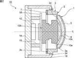
- the vibration device 1 includes a vibration element 2 including a cylindrical vibration body 3, a light transmitting body 4 provided to cover an opening of the vibration element 2, and an electric And a control unit 12 that is electrically connected.
- a hydrophilic film 5 is provided on the entire surface of the light transmitting body 4.
- the entire surface of the light transmitting body 4 refers to the entire outer surface of the vibrating device 1 that transmits light and energy rays.
- the vibration device 1 is arranged so that the optical axis L of the light transmitting body 4 is inclined from the vertical direction. More specifically, in the present embodiment, the vibration device 1 is arranged such that the optical axis L of the light transmitting body 4 is orthogonal to the vertical direction. When the vibration device 1 is arranged to be inclined at an angle of 45 ° or more with respect to the vertical direction, water droplets and the like can be particularly preferably removed from the light transmitting member 4.
- the imaging device 10 includes a cylindrical case member 18 that supports the vibration device 1 at one end, and a base member 14 that is fixed to the other end of the case member 18.
- An image sensor 10A is arranged in an internal space surrounded by the vibration device 1, the case member 18, and the base member 14. Thereby, an imaging device 10 as an optical detection device according to one embodiment of the present invention is configured.
- the imaging element 10A for example, a CMOS, a CCD, a bolometer, a thermopile, or the like that receives light of any wavelength from the visible region to the far infrared region can be used.
- the imaging device 10 include a camera, a Radar and a LIDAR device, and the like.
- the case member 18 is fixed on the base member 14.
- a plurality of legs 15 are fixed on the base member 14.
- a board 16 is fixed on the plurality of legs 15.
- the image sensor 10A is fixed on the substrate 16.
- the imaging device 10A has an imaging device body 10a and a lens module 10b. The portion on the lens module 10b side of the imaging element 10A is located in the internal space of the vibration device 1, and the remaining portion is located in the internal space of the case member 18. Note that the entire imaging element 10A may be located in the internal space of the vibration device 1.
- a circuit for driving the image sensor 10A and the control unit 12 are provided on at least one main surface of the substrate 16 or one main surface of the base member 14.
- an optical detection element other than the imaging element 10A for optically detecting an energy ray may be arranged.
- the energy ray to be detected may be, for example, an active energy ray such as an electromagnetic wave or an infrared ray.
- a field of view as a detection region of the imaging element 10 ⁇ / b> A is included in the light transmitting body 4.
- the light transmitting body 4 only needs to be disposed so as to include at least a part of the field of view of the imaging element 10A.
- the term "light-transmitting property" in the present specification refers to a light-transmitting property at which an energy ray or light having a wavelength detected by the optical detection element is transmitted.
- the imaging device 10 shown in FIGS. 1 and 2 is an example, and the configuration of the imaging device 10 is not limited to the above.
- the imaging device 10 only needs to include the vibration device 1 and the imaging element 10A.
- the vibration element 2 has a vibration body 3 and a piezoelectric vibrator 7.
- the vibrating body 3 is substantially cylindrical and has a first open end 3a and a second open end 3b.
- the direction parallel to the direction connecting the first opening end 3a and the second opening end 3b is defined as the height direction of the vibration device 1, and the direction orthogonal to the height direction is defined as the radial direction.
- the vibrating body 3 has an extension 3c located on the first opening end 3a side and extending radially inward. The portion of the extension 3c on the light transmitting body 4 side is included in the first opening end 3a.
- the light transmitting member 4 is connected to a portion of the first opening end 3a located at the extension 3c so as to cover the opening of the vibrating member 3.
- the vibrating body 3 has a hinge 3d located between the first open end 3a and the second open end 3b.
- the hinge 3d extends radially outward.
- the vibration device 1 is supported by the case member 18 at the hinge 3d.
- the thickness in the radial direction of the vibrating body 3 is a thickness
- the thickness of the portion located between the hinge 3d and the extension 3c is the thickness of the hinge 3d and the second opening end. 3b.
- the vibrating body 3 may not have the hinge portion 3d and the extension portion 3c, and the thickness of the vibrating body 3 may be the same in all portions.
- the vibrating body 3 may have a cylindrical shape.
- the vibrating body 3 may have a cylindrical shape or a rectangular cylindrical shape.
- the piezoelectric vibrator 7 is disposed at the second opening end 3 b of the vibrating body 3.
- the piezoelectric vibrator 7 vibrates the connected body of the light transmitting body 4 and the vibrating body 3.
- FIG. 3 is a schematic perspective view of the piezoelectric vibrator according to the first embodiment.
- the piezoelectric vibrator 7 has an annular piezoelectric body 8.
- the piezoelectric body 8 is made of, for example, an appropriate piezoelectric ceramic such as Pb (Zr, Ti) O 3 or (K, Na) NbO 3 or an appropriate piezoelectric single crystal such as LiTaO 3 or LiNbO 3 .
- An electrode 9a is provided on one main surface of the piezoelectric body 8, and an electrode 9b is provided on the other main surface.
- one annular piezoelectric vibrator 7 is disposed on the vibrating body 3.
- the shape and the number of the piezoelectric vibrators 7 are not limited to the above.
- a plurality of piezoelectric vibrators may be arranged along a circumferential direction with the center of the vibrating body 3 as a rotation axis.
- the light transmitting body 4 is directly connected to the vibrating body 3. Note that the light transmitting body 4 may be indirectly connected to the vibrating body 3 via another member.
- the light transmitting body 4 has a dome shape in the present embodiment.
- the shape of the light transmitting body 4 is not limited to the above, and may be, for example, a disk shape.
- the light transmitting body 4 is made of a light transmitting material.
- As the light-transmitting material for example, a light-transmitting resin, glass, or a light-transmitting ceramic can be used.
- the hydrophilic film 5 is provided on the entire surface of the light transmitting body 4. Note that the hydrophilic film 5 only needs to be provided at least in a portion including the visual field of the imaging element 10A.
- the material of the hydrophilic film 5 include TiO 2 for an inorganic type and hydrophilic PVDF for an organic type.
- the control unit 12 is electrically connected to the vibration element 2. More specifically, the control unit 12 is electrically connected to the piezoelectric vibrator 7.
- the control unit 12 controls the vibration of the connected body of the light transmitting body 4 and the vibrating body 3 by the piezoelectric vibrator 7.
- the control unit 12 vibrates the connected body of the light transmitting body 4 and the vibrating body 3 so that the node of the vibration is located at the hinge 3d of the vibrating body 3.
- the vibration device 1 can be easily supported by the case member 18, and the sealing property of the imaging device 10 can be improved.
- the support of the case member 18 makes it difficult to hinder the vibration of the vibration device 1.
- the control unit 12 of the vibration device 1 controls the vibration by the first control mode in which the vibration of the vibration element 2 and the stationary state are alternately switched.
- the hydrophilic film 5 is provided on the entire surface of the light transmitting body 4 and that the control unit 12 controls the vibration in the first control mode. Thereby, the visual field of the imaging element 10A as a detection area of the optical detection element can be more reliably secured. This will be described below.
- FIG. 4 is a schematic diagram for explaining each vibration mode.
- FIG. 4 shows the phase of vibration of each region in the light transmitting body when viewed in plan.
- the region marked with a + sign and the region marked with a-sign indicate that the phases of vibration are opposite to each other.
- the vibration mode can be represented by the (m, n) mode.
- m and n are integers.
- m is the number of vibration node lines extending in the circumferential direction
- n is the number of vibration node lines extending in the radial direction.
- the (0,0) mode is used.
- the piezoelectric vibrator 7 of the vibration device 1 is configured to be able to excite the (0, 0) mode vibration in the light transmitting body 4.
- the (0, 0) mode vibration is excited by controlling the voltage and the like applied to the piezoelectric vibrator 7 by the control unit 12.
- the hydrophilic film 5 is provided on the entire surface of the light transmitting body 4. Therefore, even if the light transmitting member 4 is vibrated, water droplets and the like are hardly atomized. This is considered for the following reasons.
- the atomization of the droplet by the vibration is due to the fact that the standing wave of the capillary wave is excited, a part of the droplet becomes columnar, and the tip of the columnar portion scatters.
- the wavelength of the capillary wave is ⁇
- the excitation frequency is f
- the surface tension of the droplet is ⁇
- the density of the droplet is ⁇
- FIG. 5 is a diagram showing the relationship between the excitation frequency f of the capillary wave and the wavelength ⁇ .
- the wavelength ⁇ of the capillary wave becomes about 10 ⁇ m, which indicates that the fog is close to a gas.
- a droplet such as a water droplet spreads on the surface of the hydrophilic film immediately after adhering to the hydrophilic film and becomes a liquid film.
- the liquid film spreads further, and the liquid film becomes thinner.
- the frequency at which the vibrating body of the vibrating device for atomizing the droplets is excited is generally about 50 kHz.
- the wavelength ⁇ of the capillary wave is about 90 ⁇ m when the excitation frequency f is about 50 kHz.
- the thickness of the liquid film is smaller than the wavelength ⁇ of the capillary wave, the standing wave of the capillary wave is hardly excited. Therefore, the liquid on the hydrophilic film is not easily atomized.
- FIGS. 6A to 6D are schematic diagrams of the vibration device according to the first embodiment for explaining the behavior of a droplet such as a water droplet when the vibration is controlled by the first control mode. It is a top view.
- the first control mode is a control mode for alternately switching the vibration and the rest of the vibration element 2.
- the light transmitting body 4 shown in FIG. 6A is vibrating in the (0,0) mode in which the antinode of vibration is located at the center.
- the droplets A move toward the center of the light transmitting body 4 where the antinode of vibration is located and gather.
- the light transmitting body 4 is stopped by the control unit 12. As a result, a force for moving the droplet A toward the center of the light transmitting member 4 is not applied to the droplet A.
- the droplets A are gathered and integrated near the center of the light transmitting body 4, the gravity applied to the droplets A increases. Therefore, the droplet A hangs down as shown in FIG. Next, as shown in FIG. 6D, the droplet A hangs down below the light transmitting body 4. Even in the case where foreign matter is included together with the droplet A, the foreign matter can hang down together with the integrated droplet A. Thereby, the droplets A and the like can be removed from the light transmitting member 4.
- the liquid may vibrate as in the case shown in FIG. It gathers in the part located on the belly, and the liquid film becomes thick in this part. Next, as in the case shown in FIGS. 6C and 6D, the liquid hangs down.
- the hydrophilic film 5 is preferably wider than the field of view. Therefore, the dropping of the droplet A can be performed more reliably.
- a vibration mode other than the (0, 0) mode is used.
- a vibration mode such as a (0, 1) mode or a (0, 2) mode may be used.
- FIGS. 7A to 7C are schematic perspective views illustrating an example of the polarization structure of the piezoelectric body according to the first embodiment.
- a region with a + sign indicates a region in which the polarization direction is from the lower surface to the upper surface in FIG. 7A of the piezoelectric body.
- a region with a minus sign indicates that the polarization direction is a direction from the upper surface to the lower surface of the piezoelectric body.
- FIGS. 7B and 7C The same applies to FIGS. 7B and 7C.
- FIG. 7A the polarization directions of the regions arranged in the circumferential direction are all the same.
- the electrodes 9a and 9b of the piezoelectric vibrator 7 shown in FIG. 3 are annular. Therefore, when the piezoelectric body 8 having the polarization structure shown in FIG. 7A is used, (0, 0) mode vibration is excited in the light transmitting body 4.
- FIG. 7B in the region divided into four in the circumferential direction, the polarization directions of the regions on both sides facing each other via the center are opposite.
- the piezoelectric body 8 having the polarization structure shown in FIG. 7B is used, the (0, 1) mode vibration is excited in the light transmitting body 4.
- FIG. 7A the electrodes 9a and 9b of the piezoelectric vibrator 7 shown in FIG. 3 are annular. Therefore, when the piezoelectric body 8 having the polarization structure shown in FIG. 7A is used, (0, 0) mode vibration is excited in the light transmitting body 4.
- FIG. 7B in the region
- the electrode 9a and the electrode 9b shown in FIG. 3 may be divided in the circumferential direction, and the divided electrodes may be arranged in the above-described regions of the piezoelectric body 8.
- the AC voltages having phases opposite to each other are applied to the regions on both sides opposed to each other with the center therebetween.
- the (0, 1) mode vibration can be excited.
- the (0, 2) mode vibration can be excited in the light transmitting member 4 by applying an AC voltage having the same phase to both regions facing each other via the center.
- the antinode of the vibration can be located at a portion not including the optical axis L of the light transmitting body 4. Thereby, even when water droplets and the like are gathered near the antinode of vibration, it is possible to suppress the obstruction of the visual field of the image sensor 10A.
- the control unit 12 controls the vibration so that the antinode of the vibration is located in a portion located in the region outside the field of view.
- the field of view of the imaging element 10A is located only near the center of the light transmitting body 4, it is preferable to use the (0, 1) mode or the (0, 2) mode in the first control mode. It is. Thereby, the field of view of the imaging element 10A is hardly hindered.
- the control unit 12 controls the vibration in the light transmitting body 4 so that a plurality of antinodes of the vibration are positioned in the vertical direction.
- antinode of the vibration is preferably located outside the central region of the light transmitting body 4.
- FIG. 8 is a schematic front sectional view of the vibration device according to the second embodiment.
- the present embodiment is different from the first embodiment in that a connecting member 26 connecting the vibrating body 23 and the light transmitting body 4 is provided. Further, the configuration of the vibrating body 23 and the control mode used are different from those of the first embodiment. Except for the above points, the vibration device of the present embodiment has the same configuration as the vibration device 1 of the first embodiment.
- the light transmitting member 4 is fixed to the connecting member 26.
- the connecting member 26 has a tubular portion 26a and a flange portion 26b extending radially outward from one end of the tubular portion 26a.
- the light transmitting body 4 is fixed to one surface of the flange portion 26b.
- the other end of the cylindrical portion 26a is fixed to the vibrating body 23.
- the light transmitting member 4 is indirectly connected to the vibrating member 23 via the connecting member 26.
- the translucent member 4 may be directly connected to the first flange portion 23d of the vibrating member 23 without using the connecting member 26.
- the first flange portion 23 d is directly connected to and integrated with the light transmitting body 4, and both are oscillated at different frequencies by the vibration of the vibrating body 3.
- the vibrating body 23 has an outer surface 23g and an inner surface 23h that connect the first open end 3a and the second open end 3b.
- the vibrating body 23 is provided with an annular support portion 23c extending radially inward from an inner side surface 23h of the vibrating body 23.
- the cylindrical portion 26a of the connecting member 26 is fixed to the support portion 23c.
- the light transmitting body 4 is connected to the vibrating body 23 by the connecting member 26.
- the support portion 23c need not be annular.
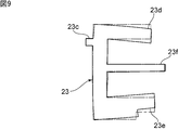
- the vibrating body 23 is usually cylindrical except for the first flange 23d, but may be provided with a second flange 23e and a third flange 23f.
- the first flange portion 23d, the second flange portion 23e, and the third flange portion 23f have an annular shape extending radially outward from an outer surface 23g of the vibrating body 23.
- the vibrating body 23 has a tripod tuning fork shape in a cross section along the radial direction and the height direction of the vibrating body 23 shown in FIG.
- the outer diameters of the first flange portion 23d, the second flange portion 23e, and the third flange portion 23f are made equal.
- the outer diameters of the first flange portion 23d, the second flange portion 23e, and the third flange portion 23f do not necessarily have to be equal.
- the first flange portion 23d is provided along the first opening end 3a, and the second flange portion 23e is provided along the second opening end 3b.
- the first flange portion 23d may be located closer to the second opening end 3b in the height direction than the first opening end 3a.
- the second flange 23e may also be located closer to the first opening end 3a than the second opening end 3b.
- control unit 12 controls the vibration in the second control mode.
- the second control mode is a mode in which the vibration is controlled such that the amplitude of the vibrating body 23 is larger than the amplitude of the light transmitting body 4.
- FIG. 9 is a schematic cross-sectional view illustrating a state of vibration of the vibrating body in the second embodiment in the second control mode.
- the solid line indicates a vibrating state
- the dashed line indicates the original state.
- the vibrator 23 has a plurality of resonance frequencies.
- a resonance frequency of a vibration mode in which the first flange portion 23d and the second flange portion 23e are displaced in opposite phases in the height direction is selected.
- Antinodes of vibration in the vibrating body 23 are located at outer peripheral edges of the first flange portion 23d and the second flange portion 23e.
- the outer peripheral edge refers to the outer peripheral edge viewed from the height direction.
- a portion between the first flange portion 23d and the second flange portion 23e is a node of vibration.
- the support portion 23c is located between the first flange portion 23d and the second flange portion 23e in the height direction.
- the support part 23c is located near the node of the vibration.
- the light transmitting body 4 is connected to the support portion 23c via a connecting member 26. Therefore, in the second control mode, the amplitude of the vibration of the vibrating body 23 is larger than the amplitude of the vibration of the light transmitting body 4.
- control may be performed such that the light transmitting body 4 does not vibrate and only the vibrating body 23 vibrates. For example, when the support portion 23c is accurately arranged at a node of the vibration, the light transmitting body 4 does not easily vibrate.
- Water droplets and the like attached to the light transmitting body 4 hang down due to gravity. Water droplets and the like reaching the first flange portion 23d from the light transmitting member 4 via the flange portion 26b of the connecting member 26 are scattered outside the first flange portion 23d by the vibration of the first flange portion 23d. Or atomized. Thereby, water droplets and the like can be more reliably removed from the translucent member 4, and the field of view of the imaging device 10A can be more reliably secured.
- the light-transmitting member 4 may be made of various light-transmitting materials, but may be made of a resin.
- the cost can be reduced.
- the mechanical Q is low, so that it is difficult to vibrate. Therefore, when atomization is performed only in the second control mode without using the first control mode, the light transmitting body 4 may be made of resin, and cost reduction can be realized.
- the control unit 12 alternately switches between the first control mode and the second control mode.
- the first control mode allows the water droplets and the like attached to the light transmitting body 4 to drop more reliably, as in the first embodiment. Water drops or the like hanging down from the light transmitting body 4 can be atomized by the second control mode. This makes it difficult for water droplets and the like to remain vertically downward.
- water droplets and the like can be more reliably and quickly drooped from the light transmitting member 4, and drainage from the light transmitting member 4 is enhanced. be able to.
- water droplets and the like can be more reliably removed, and the visual field of the image sensor 10A can be removed. Can be more reliably ensured.
- a water-repellent film is provided on the first flange portion 23d. Thereby, water droplets and the like can be more easily atomized.
- the resonance frequency of the vibration of the first flange portion 23d and the resonance frequency of the vibration of the second flange portion 23e are made substantially equal.
- the two resonance frequencies are equal. Therefore, the node of the vibration is located at the center of the vibration body 23 in the height direction.
- the third flange portion 23f is located at the center between the first flange portion 23d and the second flange portion 23e. Therefore, the third flange portion 23f is located at a node of vibration. Since the third flange portion 23f is supported by the case member 18 shown in FIG. 2, the vibration is hardly hindered.
- the region of the node of vibration is the height of the vibrating body 23. It may be shifted from the center in the height direction to the first opening end 3a side or the second opening end 3b side. In that case, it is preferable to dispose the third flange portion 23f at a position serving as a node of vibration.
- the third flange portion 23f does not necessarily have to be arranged exactly at the node of the vibration.
- the tuning fork-shaped cross-sectional shape formed by the first to third flange portions 23d to 23f is not particularly limited.
- the cross-section of the tuning fork may be a two-legged, a three-legged, a four-legged, or a five-legged or more.
- at least the first flange portion 23d and the second flange portion 23e may be provided on the outer surface 23g of the vibrating body 23.
- the vibrator 23 may have a tuning fork shape of two or more legs in cross section, and may have an outer surface shape obtained by rotating the tuning fork shape of two or more legs with respect to the center axis of the cylindrical body.
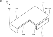
- FIG. 10 is a schematic perspective view of a light transmitting body and a case member according to the third embodiment.
- FIG. 11 is a perspective view of the vibration device according to the third embodiment, which is schematically cut away.
- the vibration device of the present embodiment includes a case member 38, and the light transmitting body 34 is directly joined to the case member 38.
- the case member 38 is a peripheral member joined to the light transmitting body 34.
- the light transmitting body 34 is a lens of the image sensor.
- the hydrophilic film 5 is provided on the entire surface of the light transmitting body 34.
- a circular opening 38a is provided on the surface of the case member 38 to which the translucent member 34 is joined.
- the opening 38a is provided with a gap from the light transmitting body 34 in a plan view.
- the vibration element 32 shown in FIG. 11 is arranged so as to seal the opening 38a.
- the vibration element 32 may be provided at a position that does not overlap the light transmitting body 34 in a plan view.
- the vibrating body 33 of the vibrating element 32 is indirectly connected to the light transmitting body 34 via a case member 38.
- the vibration element 32 causes the case member 38 to vibrate.
- the vibration element 32 has a vibration body 33 and the piezoelectric vibrator 7.
- the vibrating body 33 has a first vibrating body part 33A, a second vibrating body part 33B, and a third vibrating body part 33C.
- the second vibrating part 33B is cylindrical and has a first open end 33a and a second open end 33b.
- the first vibrating body part 33A has a disk shape, and seals the first opening end 33a of the first vibrating body part 33A.
- the third vibrating body part 33C is annular, and is connected to the second opening end 33b of the second vibrating body part 33B.
- Each vibrating part may be formed separately and joined, or each vibrating part may be formed integrally.
- the first vibrator 33A has a first flange 33d extending radially outward from a portion connected to the second vibrator 33B.
- the thickness of the first flange portion 33d is smaller than the thickness of the first vibrating body portion 33A.
- the third vibrating body part 33C has a second flange part 33e extending radially outward from a portion connected to the second vibrating body part 33B.
- the thickness of the second flange 33e is the same as the thickness of the third vibrator 33C.
- the second flange 33e is longer than the first flange 33d.
- the piezoelectric vibrator 7 of the vibration element 32 is the same piezoelectric vibrator as in the first embodiment.
- the piezoelectric vibrator 7 is arranged on a third vibrating body portion 33C of the vibrating body 33.
- the control unit 12 controls the vibration in the second control mode in addition to the control in the first control mode. That is, control is performed in the first control mode or the second control mode.
- the control of vibration in the first control mode is the same as in the first and second embodiments.
- the control unit 12 controls the vibration so that, for example, the antinode of the vibration is located in the first vibrating body 33A of the vibrating body 33.
- the vibration of the vibration element 32 propagates to the case member 38.
- water droplets and the like that hang down below the light transmitting body 34 and are located near the outer peripheral edge of the light transmitting body 34 can be moved more reliably to the vibration element 32 side.
- Water droplets and the like remaining between the light transmitting body 34 and the vibration element 32 can also be moved to the vibration element 32 side, and it is difficult to hinder the dripping of the water droplets and the like from the light transmitting body 34. Therefore, water droplets and the like can be more reliably removed from the light transmitting body 34, and the field of view of the image sensor can be more reliably secured.
- the configuration of the vibration element and the shape of the opening of the case member are not limited to the above.
- first to third modified examples of the third embodiment will be described. Also in the first to third modifications, similarly to the third embodiment, the field of view of the image sensor can be more reliably secured.
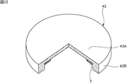
- the vibrating body 43 includes a disk-shaped first vibrating body 43A and a cylindrical second vibrating body 43B, and has a third vibrating body. do not do.
- the first vibrator 43A does not have a flange.
- the piezoelectric vibrator 7 is arranged in the first vibrator 43A, and is located in an internal space surrounded by the first vibrator 43A and the second vibrator 43B.
- the vibrating body 53 of the second modification includes a first vibrating body 53A having a rectangular plate shape and a second vibrating body 53B having a rectangular tube shape.
- the second vibrating body 53B has a first side 53a, a second side 53b, a third side 53c, and a fourth side 53d.
- the first side face 53a and the third side face 53c face each other and are connected to the long side of the first vibrating body 53A.
- the second side face 53b and the fourth side face 53d face each other and are connected to the short side of the first vibrating body 53A.
- the piezoelectric body of the piezoelectric vibrator 57 of the present modification has a rectangular plate shape. Electrodes are provided on both main surfaces of the piezoelectric body, respectively.
- the vibration element 52 has two piezoelectric vibrators 57. One piezoelectric vibrator 57 is disposed on the first side surface 53a of the second vibrator 53B, and the other piezoelectric vibrator 57 is disposed on the third side surface 53c.
- the vibrating body 63 of the third modified example includes a first vibrating body part 63A and a second vibrating body part 63B, as in the second modified example.
- the planar shape of the first vibrating body 63A is a square
- the second vibrating body 63B is a rectangular tube.
- the vibration element 62 has four piezoelectric vibrators 57 similar to those of the second modification. Each of the piezoelectric vibrators 57 is provided on the first side surface 63a, the second side surface 63b, the third side surface 63c, and the fourth side surface 63d of the second vibrating body 63B.
- Vibration Body 23c Support portions 23d to 23f First to third flange portions 23g Outside surface 23h Inner surface 26 Connecting member 26a Cylindrical portion 26b Flange portion 32 Vibrating element 33 Vibrating body 33A to 33C First to third vibrating body portions 33a, 33b: first and second opening end portions 33d, 33e: first and second flange portions 34: light transmitting member 38: case member 38a: opening portion 43: vibration Body 43A, 43B ...
- first Second vibrating body portion 52 Vibrating element 53 Vibrating bodies 53A and 53B First and second vibrating body portions 53a to 53d First to fourth side surfaces 57
Abstract
The purpose of the present invention is to provide an oscillation device capable of more reliably securing the detection area of an optical detection element. Provided is an oscillation device 1 which includes a light transmission body 4 arranged to include at least a portion of the detection area of an image capture element 10A (optical detection element) and in which the optical axis L of the light transmission body 4 is arranged obliquely relative to the vertical direction, said oscillation device further including: a hydrophilic membrane 5 provided on a portion of the light transmission body 4 which includes at least the detection area; an oscillation element 2 having an oscillating body 3 directly or indirectly connected to the light transmission body 4; and a controller 12 electrically connected to the oscillation element 2. The controller 12 controls the oscillation element 2 in a first mode where the oscillation element alternates between oscillation and non-oscillation.
Description
本発明は、機械的振動によって水滴等を除去することが可能な振動装置及び光学検出装置に関する。
The present invention relates to a vibration device and an optical detection device capable of removing water droplets and the like by mechanical vibration.
従来、監視装置として用いられるカメラ等のイメージングデバイスにおいては、その視野を常に明瞭にすることが求められている。特に、車載用途等の屋外で使用されるカメラにおいては、雨滴等の水滴を除去するための機構が種々提案されている。下記の特許文献1には、カメラ本体の前方に配置される、透光性部分を有する振動装置が開示されている。この振動装置においては、透光性部分を大きく振動させることにより、透光体部に付着した水滴を霧化させる。特許文献1には、撮影される領域以外に親水性部分を構成することにより、水滴を親水性部分側に移動させ得ることが記載されている。
Conventionally, imaging devices such as cameras used as surveillance devices have been required to always have a clear visual field. In particular, for a camera used outdoors such as in a vehicle, various mechanisms for removing water droplets such as raindrops have been proposed. Patent Literature 1 below discloses a vibration device having a light-transmitting portion disposed in front of a camera body. In this vibrating device, water droplets adhering to the light transmitting portion are atomized by vibrating the light transmitting portion largely. Patent Literature 1 describes that a water droplet can be moved to a hydrophilic portion side by forming a hydrophilic portion other than a region to be photographed.
特許文献1に記載された振動装置では、透光性部分における、カメラ本体の視野領域に位置する部分に、振動の腹及び振動の節が形成される。このとき、透光性部分に水滴が付着すると、振動の腹に向かい水滴が移動し、振動の腹付近において水滴が霧化される。しかしながら、振動の節に位置する水滴は、振動の腹の方に移動し難い。そのため、水滴が残留し、カメラ本体の視野が阻害されるおそれがあった。
振動 In the vibration device described in Patent Literature 1, antinodes of vibration and nodes of vibration are formed in a portion of the translucent portion located in the visual field region of the camera body. At this time, if a water droplet adheres to the translucent portion, the water droplet moves toward the antinode of the vibration, and the water droplet is atomized near the antinode of the vibration. However, the water droplet located at the node of the vibration is hard to move toward the antinode of the vibration. For this reason, water droplets may remain and the field of view of the camera body may be obstructed.
本発明の目的は、光学検出素子の検出領域をより確実に確保することができる、振動装置及び光学検出装置を提供することにある。
An object of the present invention is to provide a vibration device and an optical detection device that can more reliably secure a detection area of an optical detection element.
本発明に係る振動装置は、光学検出素子の検出領域の少なくとも一部を含むように配置される透光体を備え、前記透光体の光軸が鉛直方向から傾くように配置される振動装置であって、前記透光体における、少なくとも前記検出領域を含む部分に設けられている親水性膜と、前記透光体に直接的にまたは間接的に連結されている振動体を有する振動素子と、前記振動素子に電気的に接続されている制御部とをさらに備え、前記制御部が、前記振動素子の振動及び静止を交互に切り替える第1の制御モードにより振動を制御する。
A vibration device according to the present invention includes a light-transmitting member disposed so as to include at least a part of a detection region of an optical detection element, and a vibration device disposed such that an optical axis of the light-transmitting member is inclined from a vertical direction. And a vibrating element having a vibrating body directly or indirectly connected to the translucent body, wherein the hydrophilic film is provided at least in a portion including the detection region in the translucent body. A control unit electrically connected to the vibrating element, wherein the control unit controls the vibration in a first control mode in which the vibrating element alternately switches between vibration and rest.
本発明に係る光学検出装置は、本発明に従って構成された振動装置と、前記透光体に検出領域が含まれるように配置されている光学検出素子とを備える。
The optical detection device according to the present invention includes a vibration device configured according to the present invention, and an optical detection element arranged so that the light transmitting body includes a detection region.
本発明によれば、光学検出素子の検出領域をより確実に確保することができる、振動装置及び光学検出装置を提供することができる。
According to the present invention, it is possible to provide a vibration device and an optical detection device that can more reliably secure a detection area of an optical detection element.
以下、図面を参照しつつ、本発明の具体的な実施形態を説明することにより、本発明を明らかにする。
Hereinafter, the present invention will be clarified by describing specific embodiments of the present invention with reference to the drawings.
なお、本明細書に記載の各実施形態は、例示的なものであり、異なる実施形態間において、構成の部分的な置換または組み合わせが可能であることを指摘しておく。
Note that each embodiment described in the present specification is merely an example, and it should be pointed out that partial replacement or combination of configurations between different embodiments is possible.
図1は、第1の実施形態に係る振動装置を有するイメージングデバイスの模式的斜視図である。図2は、第1の実施形態に係る振動装置を有するイメージングデバイスの模式的正面断面図である。なお、図2以外の断面図や斜視図においては、後述する制御部を省略することがある。
FIG. 1 is a schematic perspective view of an imaging device having the vibration device according to the first embodiment. FIG. 2 is a schematic front sectional view of an imaging device having the vibration device according to the first embodiment. In a cross-sectional view or a perspective view other than FIG. 2, a control unit described later may be omitted.
図1に示すイメージングデバイス10は振動装置1を有する。振動装置1は、振動により水滴や異物を移動させることにより、撮像素子の視野内から水滴や異物を除去する振動装置である。図2に示すように、振動装置1は、筒状の振動体3を含む振動素子2と、振動素子2の開口部を覆うように設けられている透光体4と、振動素子2に電気的に接続されている制御部12とを有する。透光体4の全面に親水性膜5が設けられている。なお、本明細書において透光体4の全面とは、振動装置1の内部に光やエネルギー線を透過させる外表面の全面をいう。
イ メ ー ジ ン グ The imaging device 10 shown in FIG. The vibration device 1 is a vibration device that removes water droplets and foreign matter from the field of view of the image sensor by moving water droplets and foreign matter by vibration. As shown in FIG. 2, the vibration device 1 includes a vibration element 2 including a cylindrical vibration body 3, a light transmitting body 4 provided to cover an opening of the vibration element 2, and an electric And a control unit 12 that is electrically connected. A hydrophilic film 5 is provided on the entire surface of the light transmitting body 4. In this specification, the entire surface of the light transmitting body 4 refers to the entire outer surface of the vibrating device 1 that transmits light and energy rays.
振動装置1は、透光体4の光軸Lが鉛直方向から傾くように配置される。より具体的には、本実施形態では、透光体4の光軸Lが鉛直方向に直交するように振動装置1が配置される。振動装置1は、鉛直方向に対して45°以上傾くように配置される場合に、透光体4から水滴等を特に好適に除去することができる。
The vibration device 1 is arranged so that the optical axis L of the light transmitting body 4 is inclined from the vertical direction. More specifically, in the present embodiment, the vibration device 1 is arranged such that the optical axis L of the light transmitting body 4 is orthogonal to the vertical direction. When the vibration device 1 is arranged to be inclined at an angle of 45 ° or more with respect to the vertical direction, water droplets and the like can be particularly preferably removed from the light transmitting member 4.
イメージングデバイス10は、振動装置1を一端側で支持している筒状のケース部材18と、ケース部材18の他端に固定されているベース部材14とを有する。振動装置1、ケース部材18及びベース部材14により囲まれた内部空間内に、撮像素子10Aが配置されている。それによって、本発明の一実施形態に係る光学検出装置としてのイメージングデバイス10が構成されている。
The imaging device 10 includes a cylindrical case member 18 that supports the vibration device 1 at one end, and a base member 14 that is fixed to the other end of the case member 18. An image sensor 10A is arranged in an internal space surrounded by the vibration device 1, the case member 18, and the base member 14. Thereby, an imaging device 10 as an optical detection device according to one embodiment of the present invention is configured.
撮像素子10Aとしては、例えば、可視領域から遠赤外領域のいずれかの波長の光を受光する、CMOS、CCD、ボロメーターやサーモパイル等を挙げることができる。イメージングデバイス10としては、例えば、カメラ、RadarやLIDARデバイス等を挙げることができる。
As the imaging element 10A, for example, a CMOS, a CCD, a bolometer, a thermopile, or the like that receives light of any wavelength from the visible region to the far infrared region can be used. Examples of the imaging device 10 include a camera, a Radar and a LIDAR device, and the like.
図2に示すように、ケース部材18はベース部材14上に固定されている。ベース部材14上に複数の脚部15が固定されている。複数の脚部15上に基板16が固定されている。基板16上に撮像素子10Aが固定されている。撮像素子10Aは、撮像素子本体10a及びレンズモジュール10bを有する。撮像素子10Aにおけるレンズモジュール10b側の部分が、振動装置1の内部空間内に位置しており、残りの部分がケース部材18の内部空間内に位置している。なお、撮像素子10A全体が振動装置1の内部空間内に位置していてもよい。
ケ ー ス As shown in FIG. 2, the case member 18 is fixed on the base member 14. A plurality of legs 15 are fixed on the base member 14. A board 16 is fixed on the plurality of legs 15. The image sensor 10A is fixed on the substrate 16. The imaging device 10A has an imaging device body 10a and a lens module 10b. The portion on the lens module 10b side of the imaging element 10A is located in the internal space of the vibration device 1, and the remaining portion is located in the internal space of the case member 18. Note that the entire imaging element 10A may be located in the internal space of the vibration device 1.
本実施形態では、基板16の少なくとも一方の主面またはベース部材14の一方の主面に撮像素子10Aを駆動する回路や上記制御部12が設けられている。
In the present embodiment, a circuit for driving the image sensor 10A and the control unit 12 are provided on at least one main surface of the substrate 16 or one main surface of the base member 14.
なお、振動装置1、ケース部材18及びベース部材14により囲まれた内部空間内には、撮像素子10A以外の、エネルギー線を光学的に検出する光学検出素子が配置されていてもよい。検出するエネルギー線としては、例えば、電磁波や赤外線等の活性エネルギー線であってもよい。図2に示すイメージングデバイス10においては、撮像素子10Aの検出領域としての視野が、透光体4に含まれる。なお、透光体4は、撮像素子10Aの視野の少なくとも一部を含むように配置されていればよい。ここで、本明細書における透光性とは、少なくとも上記光学検出素子が検出する波長のエネルギー線や光が透過する透光性をいう。
In the internal space surrounded by the vibration device 1, the case member 18, and the base member 14, an optical detection element other than the imaging element 10A for optically detecting an energy ray may be arranged. The energy ray to be detected may be, for example, an active energy ray such as an electromagnetic wave or an infrared ray. In the imaging device 10 shown in FIG. 2, a field of view as a detection region of the imaging element 10 </ b> A is included in the light transmitting body 4. Note that the light transmitting body 4 only needs to be disposed so as to include at least a part of the field of view of the imaging element 10A. Here, the term "light-transmitting property" in the present specification refers to a light-transmitting property at which an energy ray or light having a wavelength detected by the optical detection element is transmitted.
図1及び図2に示すイメージングデバイス10は一例であって、イメージングデバイス10の構成は上記に限定されない。イメージングデバイス10は、振動装置1及び撮像素子10Aを有していればよい。
The imaging device 10 shown in FIGS. 1 and 2 is an example, and the configuration of the imaging device 10 is not limited to the above. The imaging device 10 only needs to include the vibration device 1 and the imaging element 10A.
以下において、振動装置1の詳細を説明する。
詳細 The details of the vibration device 1 will be described below.
図2に示すように、振動素子2は振動体3及び圧電振動子7を有する。本実施形態では、振動体3は略円筒状であり、第1の開口端部3a及び第2の開口端部3bを有する。ここで、第1の開口端部3a及び第2の開口端部3bを結ぶ方向に平行な方向を振動装置1の高さ方向とし、高さ方向に直交する方向を径方向とする。振動体3は、第1の開口端部3a側に位置し、径方向内側に延びる延長部3cを有する。延長部3cの透光体4側の部分は第1の開口端部3aに含まれる。上記透光体4は、振動体3の開口部を覆うように、第1の開口端部3aにおける延長部3cに位置する部分に連結されている。
振動 As shown in FIG. 2, the vibration element 2 has a vibration body 3 and a piezoelectric vibrator 7. In the present embodiment, the vibrating body 3 is substantially cylindrical and has a first open end 3a and a second open end 3b. Here, the direction parallel to the direction connecting the first opening end 3a and the second opening end 3b is defined as the height direction of the vibration device 1, and the direction orthogonal to the height direction is defined as the radial direction. The vibrating body 3 has an extension 3c located on the first opening end 3a side and extending radially inward. The portion of the extension 3c on the light transmitting body 4 side is included in the first opening end 3a. The light transmitting member 4 is connected to a portion of the first opening end 3a located at the extension 3c so as to cover the opening of the vibrating member 3.
振動体3は、第1の開口端部3aと第2の開口端部3bとの間に位置しているヒンジ部3dを有する。ヒンジ部3dは径方向外側に延びている。振動装置1は、ヒンジ部3dにおいて、ケース部材18に支持されている。ここで、振動体3の径方向における厚みを肉厚としたときに、ヒンジ部3dと延長部3cとの間に位置している部分の肉厚は、ヒンジ部3dと第2の開口端部3bとの間に位置している部分の肉厚より薄い。
The vibrating body 3 has a hinge 3d located between the first open end 3a and the second open end 3b. The hinge 3d extends radially outward. The vibration device 1 is supported by the case member 18 at the hinge 3d. Here, when the thickness in the radial direction of the vibrating body 3 is a thickness, the thickness of the portion located between the hinge 3d and the extension 3c is the thickness of the hinge 3d and the second opening end. 3b.
なお、振動体3はヒンジ部3d及び延長部3cを有していなくともよく、振動体3の肉厚は全ての部分において同じであってもよい。振動体3は筒状であればよく、例えば、振動体3は円筒状や角筒状であってもよい。
Note that the vibrating body 3 may not have the hinge portion 3d and the extension portion 3c, and the thickness of the vibrating body 3 may be the same in all portions. The vibrating body 3 may have a cylindrical shape. For example, the vibrating body 3 may have a cylindrical shape or a rectangular cylindrical shape.
振動素子2においては、振動体3の第2の開口端部3bに、圧電振動子7が配置されている。圧電振動子7は、透光体4及び振動体3の連結体を振動させる。
圧 電 In the vibrating element 2, the piezoelectric vibrator 7 is disposed at the second opening end 3 b of the vibrating body 3. The piezoelectric vibrator 7 vibrates the connected body of the light transmitting body 4 and the vibrating body 3.
図3は、第1の実施形態における圧電振動子の模式的斜視図である。
FIG. 3 is a schematic perspective view of the piezoelectric vibrator according to the first embodiment.
圧電振動子7は円環状の圧電体8を有する。圧電体8は、例えば、Pb(Zr,Ti)O3や(K,Na)NbO3等の適宜の圧電セラミックスまたはLiTaO3やLiNbO3等の適宜の圧電単結晶からなる。圧電体8の一方主面には電極9aが設けられており、他方主面には電極9bが設けられている。
The piezoelectric vibrator 7 has an annular piezoelectric body 8. The piezoelectric body 8 is made of, for example, an appropriate piezoelectric ceramic such as Pb (Zr, Ti) O 3 or (K, Na) NbO 3 or an appropriate piezoelectric single crystal such as LiTaO 3 or LiNbO 3 . An electrode 9a is provided on one main surface of the piezoelectric body 8, and an electrode 9b is provided on the other main surface.
本実施形態では、振動体3に1つの円環状の圧電振動子7が配置されている。なお、圧電振動子7の形状及び個数は上記に限定されない。例えば、平面視において、振動体3の中心を回転軸とした周回方向に沿い、複数の圧電振動子が配置されていてもよい。
In this embodiment, one annular piezoelectric vibrator 7 is disposed on the vibrating body 3. The shape and the number of the piezoelectric vibrators 7 are not limited to the above. For example, in a plan view, a plurality of piezoelectric vibrators may be arranged along a circumferential direction with the center of the vibrating body 3 as a rotation axis.
透光体4は、振動体3に直接的に連結されている。なお、透光体4は、他の部材を介して間接的に振動体3に連結されていてもよい。透光体4は、本実施形態ではドーム状である。なお、透光体4の形状は上記に限られず、例えば、円板状等であってもよい。透光体4は透光性材料からなる。透光性材料としては、例えば、透光性の樹脂、ガラスまたは透光性のセラミックス等を用いることができる。
光 The light transmitting body 4 is directly connected to the vibrating body 3. Note that the light transmitting body 4 may be indirectly connected to the vibrating body 3 via another member. The light transmitting body 4 has a dome shape in the present embodiment. The shape of the light transmitting body 4 is not limited to the above, and may be, for example, a disk shape. The light transmitting body 4 is made of a light transmitting material. As the light-transmitting material, for example, a light-transmitting resin, glass, or a light-transmitting ceramic can be used.
上述したように、透光体4の全面に親水性膜5が設けられている。なお、親水性膜5は、少なくとも撮像素子10Aの視野を含む部分に設けられていればよい。親水性膜5の材料としては、例えば、無機系ではTiO2、有機系では親水化PVDF等を挙げることができる。
As described above, the hydrophilic film 5 is provided on the entire surface of the light transmitting body 4. Note that the hydrophilic film 5 only needs to be provided at least in a portion including the visual field of the imaging element 10A. Examples of the material of the hydrophilic film 5 include TiO 2 for an inorganic type and hydrophilic PVDF for an organic type.
振動素子2に上記制御部12が電気的に接続されている。より具体的には、制御部12は圧電振動子7に電気的に接続されている。制御部12は、圧電振動子7による、透光体4及び振動体3の連結体の振動を制御する。本実施形態では、制御部12は、振動体3のヒンジ部3dに振動の節が位置するように、透光体4及び振動体3の連結体を振動させる。それによって、ケース部材18により振動装置1を容易に支持することができ、イメージングデバイス10の密閉性を高めることができる。加えて、ケース部材18による支持によって、振動装置1の振動を阻害し難い。
制 御 The control unit 12 is electrically connected to the vibration element 2. More specifically, the control unit 12 is electrically connected to the piezoelectric vibrator 7. The control unit 12 controls the vibration of the connected body of the light transmitting body 4 and the vibrating body 3 by the piezoelectric vibrator 7. In the present embodiment, the control unit 12 vibrates the connected body of the light transmitting body 4 and the vibrating body 3 so that the node of the vibration is located at the hinge 3d of the vibrating body 3. Thereby, the vibration device 1 can be easily supported by the case member 18, and the sealing property of the imaging device 10 can be improved. In addition, the support of the case member 18 makes it difficult to hinder the vibration of the vibration device 1.
振動装置1の制御部12は、振動素子2の振動及び静止を交互に切り替える第1の制御モードにより振動を制御する。
The control unit 12 of the vibration device 1 controls the vibration by the first control mode in which the vibration of the vibration element 2 and the stationary state are alternately switched.
本実施形態の特徴は、透光体4の全面に親水性膜5が設けられていること及び第1の制御モードにより振動を制御する制御部12を有することにある。それによって、光学検出素子の検出領域としての、撮像素子10Aの視野をより確実に確保することができる。これを以下において説明する。
特 徴 The features of the present embodiment are that the hydrophilic film 5 is provided on the entire surface of the light transmitting body 4 and that the control unit 12 controls the vibration in the first control mode. Thereby, the visual field of the imaging element 10A as a detection area of the optical detection element can be more reliably secured. This will be described below.
本実施形態においては、以下の振動モードを利用する。
に お い て In the present embodiment, the following vibration modes are used.
図4は、各振動モードを説明するための模式図である。図4においては、平面視したときの透光体における各領域の振動の位相を示す。+の符号が付されている領域と、-の符号が付されている領域とは、振動の位相が互いに逆であることを示す。
FIG. 4 is a schematic diagram for explaining each vibration mode. FIG. 4 shows the phase of vibration of each region in the light transmitting body when viewed in plan. The region marked with a + sign and the region marked with a-sign indicate that the phases of vibration are opposite to each other.
振動モードは(m,n)モードで表すことができる。ここで、m及びnは整数である。mは周回方向に延びる振動の節のラインの本数であり、nは径方向に延びる振動の節のラインの本数である。本実施形態においては、例えば、(0,0)モードを利用する。
The vibration mode can be represented by the (m, n) mode. Here, m and n are integers. m is the number of vibration node lines extending in the circumferential direction, and n is the number of vibration node lines extending in the radial direction. In the present embodiment, for example, the (0,0) mode is used.
ここで、振動装置1の圧電振動子7は、透光体4において(0,0)モードの振動を励振させることができるように構成されている。なお、圧電振動子7に印加する電圧等を上記制御部12により制御することによって、(0,0)モードの振動を励振させる。
Here, the piezoelectric vibrator 7 of the vibration device 1 is configured to be able to excite the (0, 0) mode vibration in the light transmitting body 4. The (0, 0) mode vibration is excited by controlling the voltage and the like applied to the piezoelectric vibrator 7 by the control unit 12.
本実施形態においては、透光体4の全面に親水性膜5が設けられている。そのため、透光体4を振動させても水滴等は霧化され難い。これは以下の理由によると考えられる。
In the present embodiment, the hydrophilic film 5 is provided on the entire surface of the light transmitting body 4. Therefore, even if the light transmitting member 4 is vibrated, water droplets and the like are hardly atomized. This is considered for the following reasons.
振動による液滴の霧化は、キャピラリーウェーブの定在波が励振されて液滴の一部が柱状となり、柱状となった部分の先端が飛散することによる。キャピラリーウェーブの波長をλ、励振周波数をf、液滴の表面張力をσ、液滴の密度をρとしたときに、波長λは下記の式1により表される。

The atomization of the droplet by the vibration is due to the fact that the standing wave of the capillary wave is excited, a part of the droplet becomes columnar, and the tip of the columnar portion scatters. When the wavelength of the capillary wave is λ, the excitation frequency is f, the surface tension of the droplet is σ, and the density of the droplet is ρ, the wavelength λ is represented by the following equation 1.
σを72.75mN/mとすると、下記の図5のような波長λの励振周波数fに対する依存性が示される。
Assuming that σ is 72.75 mN / m, the dependence of the wavelength λ on the excitation frequency f is shown in FIG. 5 below.
図5は、キャピラリーウェーブの励振周波数fと波長λとの関係を示す図である。
FIG. 5 is a diagram showing the relationship between the excitation frequency f of the capillary wave and the wavelength λ.
図5に示すように、励振周波数fが、一般的に加湿器に用いられる程度の周波数である1000kHzを超えると、キャピラリーウェーブの波長λは10μm程度となり、気体に近い霧となることがわかる。
と As shown in FIG. 5, when the excitation frequency f exceeds 1000 kHz, which is a frequency generally used for humidifiers, the wavelength λ of the capillary wave becomes about 10 μm, which indicates that the fog is close to a gas.
ここで、水滴等の液滴は親水性膜に付着した直後に親水性膜の表面に広がり液膜となる。液膜はさらに広がり、液膜の膜厚は薄くなる。液滴を霧化させる振動装置の振動体が励振される周波数は一般的に50kHz程度である。キャピラリーウェーブの波長λは、励振周波数fが50kHz程度の場合においては90μm程度である。液膜の膜厚がキャピラリーウェーブの波長λよりも薄い場合には、キャピラリーウェーブの定在波は励振され難い。そのため、親水性膜上の液は霧化され難い。
液滴 Here, a droplet such as a water droplet spreads on the surface of the hydrophilic film immediately after adhering to the hydrophilic film and becomes a liquid film. The liquid film spreads further, and the liquid film becomes thinner. The frequency at which the vibrating body of the vibrating device for atomizing the droplets is excited is generally about 50 kHz. The wavelength λ of the capillary wave is about 90 μm when the excitation frequency f is about 50 kHz. When the thickness of the liquid film is smaller than the wavelength λ of the capillary wave, the standing wave of the capillary wave is hardly excited. Therefore, the liquid on the hydrophilic film is not easily atomized.
図2に示すように、振動装置1においては、透光体4の全面に親水性膜5が設けられているため、液滴は霧化され難い。一方で、液膜が透光体4を覆うため、振動の腹に向かい液滴の移動が生じ易くなる。
As shown in FIG. 2, in the vibration device 1, since the hydrophilic film 5 is provided on the entire surface of the light transmitting body 4, droplets are not easily atomized. On the other hand, since the liquid film covers the light transmitting body 4, the movement of the droplet toward the antinode of the vibration is likely to occur.
図6(a)~図6(d)は、第1の制御モードにより振動を制御した場合の水滴等の液滴の挙動を説明するための、第1の実施形態に係る振動装置の模式的平面図である。
FIGS. 6A to 6D are schematic diagrams of the vibration device according to the first embodiment for explaining the behavior of a droplet such as a water droplet when the vibration is controlled by the first control mode. It is a top view.
図6(a)に示すように、透光体4に設けられた親水性膜5に複数の液滴Aが付着している。ここで、上述したように第1の制御モードは振動素子2の振動及び静止を交互に切り替える制御モードである。図6(a)に示す透光体4は、振動の腹が中央に位置する(0,0)モードにより振動している。次に、図6(b)に示すように、液滴Aは振動の腹が位置する透光体4の中央に向かい移動し、集合する。次に、制御部12により透光体4を静止させる。これにより、液滴Aを透光体4の中央に向かい移動させる力が液滴Aに加わらなくなる。さらに、透光体4の中央近傍に液滴Aが集合して一体となったことよって、液滴Aに加わる重力が大きくなる。よって、図6(c)に示すように、液滴Aが垂下する。次に、図6(d)に示すように、液滴Aは透光体4よりも下方へ垂下する。液滴Aと共に異物が含まれていた場合においても、集合して一体となった液滴Aと共に異物を下方へ垂下させ得る。それによって、透光体4から液滴A等を除去することができる。
複数 As shown in FIG. 6A, a plurality of droplets A adhere to the hydrophilic film 5 provided on the light transmitting body 4. Here, as described above, the first control mode is a control mode for alternately switching the vibration and the rest of the vibration element 2. The light transmitting body 4 shown in FIG. 6A is vibrating in the (0,0) mode in which the antinode of vibration is located at the center. Next, as shown in FIG. 6B, the droplets A move toward the center of the light transmitting body 4 where the antinode of vibration is located and gather. Next, the light transmitting body 4 is stopped by the control unit 12. As a result, a force for moving the droplet A toward the center of the light transmitting member 4 is not applied to the droplet A. Further, since the droplets A are gathered and integrated near the center of the light transmitting body 4, the gravity applied to the droplets A increases. Therefore, the droplet A hangs down as shown in FIG. Next, as shown in FIG. 6D, the droplet A hangs down below the light transmitting body 4. Even in the case where foreign matter is included together with the droplet A, the foreign matter can hang down together with the integrated droplet A. Thereby, the droplets A and the like can be removed from the light transmitting member 4.
なお、透光体4に設けられた親水性膜5の全面に液膜が広がり、液が液滴という形態にならない場合においても、図6(b)に示す場合と同様に、液が振動の腹に位置する部分に集合し、該部分において液膜の膜厚が厚くなる。次に、図6(c)及び図6(d)に示す場合と同様に、液が垂下する。
Note that, even when the liquid film spreads over the entire surface of the hydrophilic film 5 provided on the light transmitting body 4 and the liquid does not form a droplet, the liquid may vibrate as in the case shown in FIG. It gathers in the part located on the belly, and the liquid film becomes thick in this part. Next, as in the case shown in FIGS. 6C and 6D, the liquid hangs down.
第1の制御モードにより振動素子2の振動及び静止を繰り返すことにより、水滴等をより確実に除去することができ、撮像素子10Aの視野をより確実に確保することができる。加えて、水滴等を霧化させる必要はないため、圧電振動子7に高電圧を印加する必要はない。従って、効率的に水滴等を除去することができる。
(4) By repeatedly oscillating and stopping the vibration element 2 in the first control mode, water droplets and the like can be more reliably removed, and the field of view of the imaging element 10A can be more reliably secured. In addition, since it is not necessary to atomize water droplets or the like, it is not necessary to apply a high voltage to the piezoelectric vibrator 7. Therefore, water droplets and the like can be efficiently removed.
また、親水性膜5は、撮像素子10Aの視野が透光体4内に位置している場合には、親水性膜5は、視野よりも広いことが好ましい。それによって、液滴Aの垂下をより確実に行うことができる。
In addition, when the field of view of the imaging element 10A is located in the light transmitting body 4, the hydrophilic film 5 is preferably wider than the field of view. Thereby, the dropping of the droplet A can be performed more reliably.
本実施形態では、第1の制御モードにおいて、透光体4を振動させる際に、(0,0)モードを利用する例を示しているが、(0,0)モード以外の振動モードを利用してもよい。例えば、下記に示すように、(0,1)モードや(0,2)モード等の振動モードを利用してもよい。
In the present embodiment, an example in which the (0, 0) mode is used when the light transmitting body 4 is vibrated in the first control mode, but a vibration mode other than the (0, 0) mode is used. May be. For example, as described below, a vibration mode such as a (0, 1) mode or a (0, 2) mode may be used.
図7(a)~図7(c)は、第1の実施形態における圧電体の分極構造の例を説明するための模式的斜視図である。図7(a)において、+の符号が付されている領域は、分極方向が圧電体の図7(a)における下面から上面に向かう方向となっている領域であることを示す。-の符号が付されている領域は、分極方向が圧電体の上面から下面に向かう方向となっている領域であることを示す。図7(b)及び図7(c)においても同様である。
FIGS. 7A to 7C are schematic perspective views illustrating an example of the polarization structure of the piezoelectric body according to the first embodiment. In FIG. 7A, a region with a + sign indicates a region in which the polarization direction is from the lower surface to the upper surface in FIG. 7A of the piezoelectric body. A region with a minus sign indicates that the polarization direction is a direction from the upper surface to the lower surface of the piezoelectric body. The same applies to FIGS. 7B and 7C.
図7(a)では、周回方向に配置された領域の分極方向が全て同じである。ここで、図3に示す圧電振動子7の電極9a及び電極9bは円環状である。よって、図7(a)に示す分極構造の圧電体8を用いる場合、透光体4において(0,0)モードの振動が励振される。図7(b)では、周回方向に4分割された領域において、中心を介して対向している両側の領域の分極方向が反対となっている。図7(b)に示す分極構造の圧電体8を用いる場合、透光体4において(0,1)モードの振動が励振される。図7(c)では、周回方向に4分割された領域において、中心を介して対向している両側の領域の分極方向が等しくされている。図7(c)に示す分極構造の圧電体8を用いる場合、透光体4において(0,2)モードの振動が励振される。
で は In FIG. 7A, the polarization directions of the regions arranged in the circumferential direction are all the same. Here, the electrodes 9a and 9b of the piezoelectric vibrator 7 shown in FIG. 3 are annular. Therefore, when the piezoelectric body 8 having the polarization structure shown in FIG. 7A is used, (0, 0) mode vibration is excited in the light transmitting body 4. In FIG. 7B, in the region divided into four in the circumferential direction, the polarization directions of the regions on both sides facing each other via the center are opposite. When the piezoelectric body 8 having the polarization structure shown in FIG. 7B is used, the (0, 1) mode vibration is excited in the light transmitting body 4. In FIG. 7C, in the region divided into four in the circumferential direction, the polarization directions of both regions facing each other with the center therebetween are equalized. When the piezoelectric body 8 having the polarization structure shown in FIG. 7C is used, (0, 2) mode vibration is excited in the light transmitting body 4.
ここで、図3に示した電極9a及び電極9bは周回方向において分割されていてもよく、分割された各電極が圧電体8の上記各領域に配置されていてもよい。この場合には、図7(a)に示す分極構造の圧電体8を用いる場合においても、中心を介して対向している両側の領域に互いに逆の位相の交流電圧を印加することにより、透光体4において(0,1)モードの振動を励振させることができる。あるいは、中心を介して対向している両側の領域に同じ位相の交流電圧を印加することにより、透光体4において(0,2)モードの振動を励振させることができる。
Here, the electrode 9a and the electrode 9b shown in FIG. 3 may be divided in the circumferential direction, and the divided electrodes may be arranged in the above-described regions of the piezoelectric body 8. In this case, even when the piezoelectric body 8 having the polarization structure shown in FIG. 7A is used, the AC voltages having phases opposite to each other are applied to the regions on both sides opposed to each other with the center therebetween. In the optical body 4, the (0, 1) mode vibration can be excited. Alternatively, the (0, 2) mode vibration can be excited in the light transmitting member 4 by applying an AC voltage having the same phase to both regions facing each other via the center.
(0,1)モードまたは(0,2)モードを利用した場合には、透光体4の光軸Lを含まない部分に振動の腹を位置させることができる。それによって、水滴等を振動の腹近傍に集合させたときにおいても、撮像素子10Aの視野の阻害を抑制することができる。
When the (0, 1) mode or the (0, 2) mode is used, the antinode of the vibration can be located at a portion not including the optical axis L of the light transmitting body 4. Thereby, even when water droplets and the like are gathered near the antinode of vibration, it is possible to suppress the obstruction of the visual field of the image sensor 10A.
透光体4が撮像素子10Aの視野外の領域に位置する部分を有する場合には、視野外の領域に位置する部分に振動の腹が位置するように、制御部12が振動を制御することが好ましい。例えば、撮像素子10Aの視野が透光体4の中央付近のみに位置する場合には、第1の制御モードにおいて、(0,1)モードまたは(0,2)モード等を利用することが好適である。それによって、撮像素子10Aの視野がより一層阻害され難い。
When the light transmitting body 4 has a portion located in a region outside the field of view of the image sensor 10A, the control unit 12 controls the vibration so that the antinode of the vibration is located in a portion located in the region outside the field of view. Is preferred. For example, when the field of view of the imaging element 10A is located only near the center of the light transmitting body 4, it is preferable to use the (0, 1) mode or the (0, 2) mode in the first control mode. It is. Thereby, the field of view of the imaging element 10A is hardly hindered.
あるいは、透光体4の光軸Lが鉛直方向から傾くように配置されたときに、透光体4において、鉛直方向において振動の腹が複数位置するように、制御部12が振動を制御してもよい。この場合には、複数の位置から下方へ水滴等を速やかに移動させることができる。より好ましくは、振動の腹は、透光体4の中央領域外に位置していることが望ましい。それによって、視野の中央における明瞭度を改善することができ、かつ水滴等の分散による垂下効率の向上を図ることができる。
Alternatively, when the optical axis L of the light transmitting body 4 is arranged to be inclined from the vertical direction, the control unit 12 controls the vibration in the light transmitting body 4 so that a plurality of antinodes of the vibration are positioned in the vertical direction. You may. In this case, water droplets and the like can be quickly moved downward from a plurality of positions. More preferably, the antinode of the vibration is preferably located outside the central region of the light transmitting body 4. Thereby, the clarity at the center of the visual field can be improved, and the drooping efficiency can be improved by dispersion of water droplets and the like.
図8は、第2の実施形態に係る振動装置の模式的正面断面図である。
FIG. 8 is a schematic front sectional view of the vibration device according to the second embodiment.
本実施形態は、振動体23と透光体4とを連結している連結部材26を有する点が第1の実施形態と異なる。さらに、振動体23の構成及び用いる制御モードが第1の実施形態と異なる。上記の点以外においては、本実施形態の振動装置は第1の実施形態の振動装置1と同様の構成を有する。
The present embodiment is different from the first embodiment in that a connecting member 26 connecting the vibrating body 23 and the light transmitting body 4 is provided. Further, the configuration of the vibrating body 23 and the control mode used are different from those of the first embodiment. Except for the above points, the vibration device of the present embodiment has the same configuration as the vibration device 1 of the first embodiment.
透光体4が、連結部材26に固定されている。連結部材26は筒状部26aと、筒状部26aの一端から径方向外側に延ばされたフランジ部26bとを有する。フランジ部26bの一方の面に、透光体4が固定されている。筒状部26aの他端が、振動体23に固定されている。このように、透光体4は、連結部材26を介して間接的に振動体23に連結されている。
光 The light transmitting member 4 is fixed to the connecting member 26. The connecting member 26 has a tubular portion 26a and a flange portion 26b extending radially outward from one end of the tubular portion 26a. The light transmitting body 4 is fixed to one surface of the flange portion 26b. The other end of the cylindrical portion 26a is fixed to the vibrating body 23. Thus, the light transmitting member 4 is indirectly connected to the vibrating member 23 via the connecting member 26.
なお、透光体4は、振動体23の第1のフランジ部23dに連結部材26を介さず、直接的に連結されていてもよい。その結果、第1のフランジ部23dは直接透光体4と接続され一体となり、振動体3の振動により両者とも異なった周波数で振動可能な状態に置かれる。
The translucent member 4 may be directly connected to the first flange portion 23d of the vibrating member 23 without using the connecting member 26. As a result, the first flange portion 23 d is directly connected to and integrated with the light transmitting body 4, and both are oscillated at different frequencies by the vibration of the vibrating body 3.
振動体23は、第1の開口端部3a及び第2の開口端部3bを接続する、外側面23g及び内側面23hを有する。振動体23には、振動体23の内側面23hから径方向内側に延ばされた円環状の支持部23cが設けられている。支持部23cに、連結部材26の筒状部26aが固定されている。それによって、透光体4が振動体23に連結部材26により連結されている。なお、支持部23cは円環状でなくともよい。
The vibrating body 23 has an outer surface 23g and an inner surface 23h that connect the first open end 3a and the second open end 3b. The vibrating body 23 is provided with an annular support portion 23c extending radially inward from an inner side surface 23h of the vibrating body 23. The cylindrical portion 26a of the connecting member 26 is fixed to the support portion 23c. Thus, the light transmitting body 4 is connected to the vibrating body 23 by the connecting member 26. Note that the support portion 23c need not be annular.
振動体23は、第1のフランジ部23dを除いて通常は円筒状であるが、第2のフランジ部23eと第3のフランジ部23fとを設けてもよい。第1のフランジ部23d、第2のフランジ部23e及び第3のフランジ部23fは、振動体23の外側面23gから径方向外側に延ばされた、円環状の形状を有する。振動体23は、図8に示す振動体23の径方向及び高さ方向に沿う断面において、三脚音叉状の形状を有する。本実施形態では、第1のフランジ部23d、第2のフランジ部23e及び第3のフランジ部23fの外径は等しくされている。もっとも、第1のフランジ部23d、第2のフランジ部23e及び第3のフランジ部23fの外径は必ずしも等しくなくともよい。
The vibrating body 23 is usually cylindrical except for the first flange 23d, but may be provided with a second flange 23e and a third flange 23f. The first flange portion 23d, the second flange portion 23e, and the third flange portion 23f have an annular shape extending radially outward from an outer surface 23g of the vibrating body 23. The vibrating body 23 has a tripod tuning fork shape in a cross section along the radial direction and the height direction of the vibrating body 23 shown in FIG. In the present embodiment, the outer diameters of the first flange portion 23d, the second flange portion 23e, and the third flange portion 23f are made equal. However, the outer diameters of the first flange portion 23d, the second flange portion 23e, and the third flange portion 23f do not necessarily have to be equal.
また、第1のフランジ部23dは、第1の開口端部3aに沿うように設けられており、第2のフランジ部23eは、第2の開口端部3bに沿うように設けられている。もっとも、第1のフランジ部23dは第1の開口端部3aよりも高さ方向において第2の開口端部3b側に位置していてもよい。第2のフランジ部23eについても、第2の開口端部3bよりも第1の開口端部3a側に位置していてもよい。
The first flange portion 23d is provided along the first opening end 3a, and the second flange portion 23e is provided along the second opening end 3b. However, the first flange portion 23d may be located closer to the second opening end 3b in the height direction than the first opening end 3a. The second flange 23e may also be located closer to the first opening end 3a than the second opening end 3b.
本実施形態では、制御部12が第2の制御モードにより振動を制御する。第2の制御モードは、振動体23の振幅が透光体4の振幅よりも大きくなるように振動を制御するモードである。
In the present embodiment, the control unit 12 controls the vibration in the second control mode. The second control mode is a mode in which the vibration is controlled such that the amplitude of the vibrating body 23 is larger than the amplitude of the light transmitting body 4.
図9は、第2の実施形態における振動体の、第2の制御モードにおける振動の状態を説明するための模式的断面図である。図9において、実線は振動している状態を示し、一点鎖線は元の状態を示す。
FIG. 9 is a schematic cross-sectional view illustrating a state of vibration of the vibrating body in the second embodiment in the second control mode. In FIG. 9, the solid line indicates a vibrating state, and the dashed line indicates the original state.
振動体23には複数の共振周波数が存在する。第2の制御モードにおいては、図9に示すように、第1のフランジ部23dと、第2のフランジ部23eとが高さ方向に対し逆相で変位する振動モードの共振周波数を選択する。振動体23における振動の腹は、第1のフランジ部23d及び第2のフランジ部23eの外周縁に位置する。本明細書において外周縁とは、高さ方向から見た外周縁をいう。他方、第1のフランジ部23dと、第2のフランジ部23eとの間の部分が振動の節となっている。支持部23cは、高さ方向において、第1のフランジ部23dと第2のフランジ部23eとの間に位置している。よって、支持部23cは振動の節付近に位置している。この支持部23cに連結部材26を介して透光体4が連結されている。従って、第2の制御モードにおいては、振動体23の振動の振幅は透光体4の振動の振幅よりも大きい。
The vibrator 23 has a plurality of resonance frequencies. In the second control mode, as shown in FIG. 9, a resonance frequency of a vibration mode in which the first flange portion 23d and the second flange portion 23e are displaced in opposite phases in the height direction is selected. Antinodes of vibration in the vibrating body 23 are located at outer peripheral edges of the first flange portion 23d and the second flange portion 23e. In this specification, the outer peripheral edge refers to the outer peripheral edge viewed from the height direction. On the other hand, a portion between the first flange portion 23d and the second flange portion 23e is a node of vibration. The support portion 23c is located between the first flange portion 23d and the second flange portion 23e in the height direction. Therefore, the support part 23c is located near the node of the vibration. The light transmitting body 4 is connected to the support portion 23c via a connecting member 26. Therefore, in the second control mode, the amplitude of the vibration of the vibrating body 23 is larger than the amplitude of the vibration of the light transmitting body 4.
なお、第2の制御モードにおいて、透光体4が振動せず、振動体23のみが振動するように制御されてもよい。例えば、支持部23cが振動の節に正確に配置されている場合には、透光体4は振動し難い。
In the second control mode, control may be performed such that the light transmitting body 4 does not vibrate and only the vibrating body 23 vibrates. For example, when the support portion 23c is accurately arranged at a node of the vibration, the light transmitting body 4 does not easily vibrate.
透光体4に付着した水滴等は、重力により垂下する。透光体4から連結部材26のフランジ部26bを介して、第1のフランジ部23dに至った水滴等が、上記第1のフランジ部23dの振動により第1のフランジ部23dの外に飛散されたり、霧化されたりする。それによって、透光体4から水滴等をより確実に除去することができ、撮像素子10Aの視野をより確実に確保することができる。
水 Water droplets and the like attached to the light transmitting body 4 hang down due to gravity. Water droplets and the like reaching the first flange portion 23d from the light transmitting member 4 via the flange portion 26b of the connecting member 26 are scattered outside the first flange portion 23d by the vibration of the first flange portion 23d. Or atomized. Thereby, water droplets and the like can be more reliably removed from the translucent member 4, and the field of view of the imaging device 10A can be more reliably secured.
なお、透光体4は、様々な透光性材料より構成され得るが、樹脂を用いてもよい。透光体4が樹脂からなる場合、コストを低めることができる。樹脂からなる透光体4の場合、機械的Qが低いため、振動し難い。従って、第1の制御モードを用いずに、第2の制御モードによりのみ霧化を行う場合には、透光体4は樹脂からなっていてもよく、低コスト化を実現することができる。
The light-transmitting member 4 may be made of various light-transmitting materials, but may be made of a resin. When the light transmitting body 4 is made of a resin, the cost can be reduced. In the case of the light transmitting body 4 made of resin, the mechanical Q is low, so that it is difficult to vibrate. Therefore, when atomization is performed only in the second control mode without using the first control mode, the light transmitting body 4 may be made of resin, and cost reduction can be realized.
制御部12は、第1の制御モード及び第2の制御モードを交互に切り替えることが好ましい。例えば、第1のフランジ部23dと透光体4とが直接接合されている形状で振動子を励振すると、透光体4と第1のフランジ部23dとがそれぞれが異なった共振周波数をもつことが可能となる。この場合には、第1の制御モードにより、第1の実施形態と同様に、透光体4に付着した水滴等をより一層確実に垂下させることができる。透光体4から垂下した水滴等を、第2の制御モードにより霧化させることができる。それによって、鉛直方向下方に水滴等が残留し難い。従って、第2の制御モードから第1の制御モードに切り替えたとき、透光体4から水滴等をより一層確実に、かつ速やかに垂下させることができ、透光体4からの排水性を高めることができる。このように、第1の制御モード及び第2の制御モードを交互に切り替え、水滴等の垂下及び霧化を繰り返すことにより、水滴等をより一層確実に除去することができ、撮像素子10Aの視野をより一層確実に確保することができる。
It is preferable that the control unit 12 alternately switches between the first control mode and the second control mode. For example, when the vibrator is excited in a shape in which the first flange portion 23d and the light transmitting member 4 are directly joined, the light transmitting member 4 and the first flange portion 23d have different resonance frequencies. Becomes possible. In this case, the first control mode allows the water droplets and the like attached to the light transmitting body 4 to drop more reliably, as in the first embodiment. Water drops or the like hanging down from the light transmitting body 4 can be atomized by the second control mode. This makes it difficult for water droplets and the like to remain vertically downward. Therefore, when switching from the second control mode to the first control mode, water droplets and the like can be more reliably and quickly drooped from the light transmitting member 4, and drainage from the light transmitting member 4 is enhanced. be able to. In this manner, by alternately switching between the first control mode and the second control mode and repeating dripping and atomization of water droplets and the like, water droplets and the like can be more reliably removed, and the visual field of the image sensor 10A can be removed. Can be more reliably ensured.
第1のフランジ部23dには、撥水性膜が設けられていることが好ましい。それによって、水滴等をより一層容易に霧化させることができる。
水性 It is preferable that a water-repellent film is provided on the first flange portion 23d. Thereby, water droplets and the like can be more easily atomized.
第1のフランジ部23dの振動の共振周波数と、第2のフランジ部23eの振動の共振周波数とがほぼ等しくされることが好ましい。本実施形態では、両者の共振周波数が等しくされている。よって、振動の節が、振動体23の高さ方向中央に位置している。ここで、第3のフランジ部23fは、第1のフランジ部23dと第2のフランジ部23eとの間の中央に位置している。従って、第3のフランジ部23fは振動の節に位置している。図2に示したケース部材18により第3のフランジ部23fが支持されることにより、振動が阻害され難い。
。 It is preferable that the resonance frequency of the vibration of the first flange portion 23d and the resonance frequency of the vibration of the second flange portion 23e are made substantially equal. In the present embodiment, the two resonance frequencies are equal. Therefore, the node of the vibration is located at the center of the vibration body 23 in the height direction. Here, the third flange portion 23f is located at the center between the first flange portion 23d and the second flange portion 23e. Therefore, the third flange portion 23f is located at a node of vibration. Since the third flange portion 23f is supported by the case member 18 shown in FIG. 2, the vibration is hardly hindered.
もっとも、第1のフランジ部23dと第2のフランジ部23eとが、振動体23の高さ方向中央に対して対称に設けられていない場合には、振動の節の領域は振動体23の高さ方向中央から第1の開口端部3a側または第2の開口端部3b側にずれることがある。その場合には、振動の節となる位置に第3のフランジ部23fを配置することが好ましい。もっとも、第3のフランジ部23fは、必ずしも振動の節に正確に配置されなくともよい。本発明における振動体23においては、第1~第3のフランジ部23d~23fで構成される音叉状の断面形状は特に限定されない。すなわち、音叉状の断面形状は、二脚であってもよく、三脚であってもよく、四脚であってもよく、五脚以上であってもよい。本発明においては、少なくとも第1のフランジ部23dと第2のフランジ部23eとが振動体23の外側面23gに設けられていればよい。振動体23は、断面において二脚以上の音叉形状を有し、その二脚以上の断面音叉形状を円筒体の中心軸に対して回転させた外面形状を有していればよい。
However, when the first flange portion 23d and the second flange portion 23e are not provided symmetrically with respect to the center in the height direction of the vibrating body 23, the region of the node of vibration is the height of the vibrating body 23. It may be shifted from the center in the height direction to the first opening end 3a side or the second opening end 3b side. In that case, it is preferable to dispose the third flange portion 23f at a position serving as a node of vibration. However, the third flange portion 23f does not necessarily have to be arranged exactly at the node of the vibration. In the vibrating body 23 of the present invention, the tuning fork-shaped cross-sectional shape formed by the first to third flange portions 23d to 23f is not particularly limited. That is, the cross-section of the tuning fork may be a two-legged, a three-legged, a four-legged, or a five-legged or more. In the present invention, at least the first flange portion 23d and the second flange portion 23e may be provided on the outer surface 23g of the vibrating body 23. The vibrator 23 may have a tuning fork shape of two or more legs in cross section, and may have an outer surface shape obtained by rotating the tuning fork shape of two or more legs with respect to the center axis of the cylindrical body.
図10は、第3の実施形態における透光体及びケース部材の模式的斜視図である。図11は、第3の実施形態における振動装置の模式的部分切欠き斜視図である。
FIG. 10 is a schematic perspective view of a light transmitting body and a case member according to the third embodiment. FIG. 11 is a perspective view of the vibration device according to the third embodiment, which is schematically cut away.
図10に示すように、本実施形態の振動装置はケース部材38を含み、ケース部材38に透光体34が直接的に接合されている。本実施形態では、ケース部材38は透光体34に接合された周辺部材である。透光体34は撮像素子のレンズである。透光体34の全面に親水性膜5が設けられている。ケース部材38の透光体34が接合された面上には、円形の開口部38aが設けられている。開口部38aは、平面視において、透光体34とギャップを隔てて設けられている。開口部38aを封止するように、図11に示す振動素子32が配置される。このように、平面視において、透光体34に重ならない位置に振動素子32が設けられていてもよい。振動素子32の振動体33は、ケース部材38を介して間接的に透光体34に連結されている。振動素子32はケース部材38を振動させる。
As shown in FIG. 10, the vibration device of the present embodiment includes a case member 38, and the light transmitting body 34 is directly joined to the case member 38. In the present embodiment, the case member 38 is a peripheral member joined to the light transmitting body 34. The light transmitting body 34 is a lens of the image sensor. The hydrophilic film 5 is provided on the entire surface of the light transmitting body 34. A circular opening 38a is provided on the surface of the case member 38 to which the translucent member 34 is joined. The opening 38a is provided with a gap from the light transmitting body 34 in a plan view. The vibration element 32 shown in FIG. 11 is arranged so as to seal the opening 38a. As described above, the vibration element 32 may be provided at a position that does not overlap the light transmitting body 34 in a plan view. The vibrating body 33 of the vibrating element 32 is indirectly connected to the light transmitting body 34 via a case member 38. The vibration element 32 causes the case member 38 to vibrate.
図11に示すように、振動素子32は振動体33及び圧電振動子7を有する。振動体33は、第1の振動体部33A、第2の振動体部33B及び第3の振動体部33Cを有する。第2の振動体部33Bは円筒状であり、第1の開口端部33a及び第2の開口端部33bを有する。第1の振動体部33Aは円板状であり、第1の振動体部33Aの第1の開口端部33aを封止している。第3の振動体部33Cは円環状であり、第2の振動体部33Bの第2の開口端部33bに連結されている。各振動体部が別体として形成され、接合されていてもよく、各振動体部が一体として形成されていてもよい。
振動 As shown in FIG. 11, the vibration element 32 has a vibration body 33 and the piezoelectric vibrator 7. The vibrating body 33 has a first vibrating body part 33A, a second vibrating body part 33B, and a third vibrating body part 33C. The second vibrating part 33B is cylindrical and has a first open end 33a and a second open end 33b. The first vibrating body part 33A has a disk shape, and seals the first opening end 33a of the first vibrating body part 33A. The third vibrating body part 33C is annular, and is connected to the second opening end 33b of the second vibrating body part 33B. Each vibrating part may be formed separately and joined, or each vibrating part may be formed integrally.
第1の振動体部33Aは、第2の振動体部33Bに連結されている部分から径方向外側に延びる第1のフランジ部33dを有する。第1のフランジ部33dの厚みは第1の振動体部33Aの厚みよりも薄い。第3の振動体部33Cは、第2の振動体部33Bに連結されている部分から径方向外側に延びる第2のフランジ部33eを有する。第2のフランジ部33eの厚みは、第3の振動体部33Cの厚みと同じである。ここで、径方向における、第1の振動体部33Aまたは第3の振動体部33Cの第2の振動体部33Bの外周縁に連結された位置から、径方向にフランジ部が延びる長さをフランジ部の長さとする。本実施形態では、第2のフランジ部33eが第1のフランジ部33dより長い。
The first vibrator 33A has a first flange 33d extending radially outward from a portion connected to the second vibrator 33B. The thickness of the first flange portion 33d is smaller than the thickness of the first vibrating body portion 33A. The third vibrating body part 33C has a second flange part 33e extending radially outward from a portion connected to the second vibrating body part 33B. The thickness of the second flange 33e is the same as the thickness of the third vibrator 33C. Here, the radially extending length of the flange portion from the position connected to the outer peripheral edge of the first vibrating body portion 33A or the third vibrating body portion 33B of the third vibrating body portion 33C in the radial direction. Length of flange. In the present embodiment, the second flange 33e is longer than the first flange 33d.
振動素子32の圧電振動子7は第1の実施形態と同様の圧電振動子である。圧電振動子7は、振動体33の第3の振動体部33Cに配置されている。
圧 電 The piezoelectric vibrator 7 of the vibration element 32 is the same piezoelectric vibrator as in the first embodiment. The piezoelectric vibrator 7 is arranged on a third vibrating body portion 33C of the vibrating body 33.
本実施形態では、制御部12は前述した第1の制御モードによる制御に加えて、第2の制御モードによっても振動を制御する。すなわち、第1の制御モードまたは第2の制御モードで制御が行われる。第1の制御モードによる振動の制御は、第1及び第2の実施形態の場合と同様である。第2の制御モードでは、制御部12は、例えば、振動体33の第1の振動体部33Aに振動の腹が位置するように振動を制御する。振動素子32の振動はケース部材38に伝搬する。それによって、透光体34の下方に垂下し、透光体34の外周縁付近に位置している水滴等を振動素子32側により確実に移動させることができる。透光体34と振動素子32との間に残留している水滴等も振動素子32側に移動させることができ、透光体34からの水滴等の垂下を阻害し難い。従って、透光体34から水滴等をより確実に除去することができ、撮像素子の視野をより確実に確保することができる。
In the present embodiment, the control unit 12 controls the vibration in the second control mode in addition to the control in the first control mode. That is, control is performed in the first control mode or the second control mode. The control of vibration in the first control mode is the same as in the first and second embodiments. In the second control mode, the control unit 12 controls the vibration so that, for example, the antinode of the vibration is located in the first vibrating body 33A of the vibrating body 33. The vibration of the vibration element 32 propagates to the case member 38. Thus, water droplets and the like that hang down below the light transmitting body 34 and are located near the outer peripheral edge of the light transmitting body 34 can be moved more reliably to the vibration element 32 side. Water droplets and the like remaining between the light transmitting body 34 and the vibration element 32 can also be moved to the vibration element 32 side, and it is difficult to hinder the dripping of the water droplets and the like from the light transmitting body 34. Therefore, water droplets and the like can be more reliably removed from the light transmitting body 34, and the field of view of the image sensor can be more reliably secured.
なお、振動素子の構成やケース部材の開口部の形状は上記に限定されない。以下において、第3の実施形態の第1~第3の変形例を示す。第1~第3の変形例においても、第3の実施形態と同様に、撮像素子の視野をより確実に確保することができる。
The configuration of the vibration element and the shape of the opening of the case member are not limited to the above. Hereinafter, first to third modified examples of the third embodiment will be described. Also in the first to third modifications, similarly to the third embodiment, the field of view of the image sensor can be more reliably secured.
図12に示す第1の変形例においては、振動体43は、円板状の第1の振動体部43A及び円筒状の第2の振動体部43Bからなり、第3の振動体部を有しない。第1の振動体部43Aはフランジ部を有しない。圧電振動子7は、第1の振動体部43Aに配置されており、かつ第1の振動体部43A及び第2の振動体部43Bにより囲まれた内部空間内に位置する。
In the first modified example shown in FIG. 12, the vibrating body 43 includes a disk-shaped first vibrating body 43A and a cylindrical second vibrating body 43B, and has a third vibrating body. do not do. The first vibrator 43A does not have a flange. The piezoelectric vibrator 7 is arranged in the first vibrator 43A, and is located in an internal space surrounded by the first vibrator 43A and the second vibrator 43B.
図13に示すように、第2の変形例においては、ケース部材58の開口部58aは矩形である。図14に示すように、第2の変形例の振動体53は、矩形板状の第1の振動体部53A及び角筒状の第2の振動体部53Bからなる。第2の振動体部53Bは、第1の側面53a、第2の側面53b、第3の側面53c及び第4の側面53dを有する。第1の側面53a及び第3の側面53cは互いに対向しており、第1の振動体部53Aの長辺に連結されている。第2の側面53b及び第4の側面53dは互いに対向しており、第1の振動体部53Aの短辺に連結されている。
開口 As shown in FIG. 13, in the second modification, the opening 58a of the case member 58 is rectangular. As shown in FIG. 14, the vibrating body 53 of the second modification includes a first vibrating body 53A having a rectangular plate shape and a second vibrating body 53B having a rectangular tube shape. The second vibrating body 53B has a first side 53a, a second side 53b, a third side 53c, and a fourth side 53d. The first side face 53a and the third side face 53c face each other and are connected to the long side of the first vibrating body 53A. The second side face 53b and the fourth side face 53d face each other and are connected to the short side of the first vibrating body 53A.
本変形例の圧電振動子57の圧電体は矩形板状である。圧電体の両主面にそれぞれ電極が設けられている。振動素子52は2つの圧電振動子57を有する。一方の圧電振動子57は、第2の振動体部53Bの第1の側面53aに配置されており、他方の圧電振動子57は第3の側面53cに配置されている。
圧 電 The piezoelectric body of the piezoelectric vibrator 57 of the present modification has a rectangular plate shape. Electrodes are provided on both main surfaces of the piezoelectric body, respectively. The vibration element 52 has two piezoelectric vibrators 57. One piezoelectric vibrator 57 is disposed on the first side surface 53a of the second vibrator 53B, and the other piezoelectric vibrator 57 is disposed on the third side surface 53c.
第3の変形例におけるケース部材の開口部は正方形である。図15に示すように、第3の変形例の振動体63は、第2の変形例と同様に、第1の振動体部63A及び第2の振動体部63Bからなる。第1の振動体部63Aの平面形状は正方形であり、第2の振動体部63Bは角筒状である。振動素子62は、第2の変形例と同様の圧電振動子57を4つ有する。各圧電振動子57は、第2の振動体部63Bの第1の側面63a、第2の側面63b、第3の側面63c及び第4の側面63dにそれぞれ設けられている。
開口 The opening of the case member in the third modification is square. As shown in FIG. 15, the vibrating body 63 of the third modified example includes a first vibrating body part 63A and a second vibrating body part 63B, as in the second modified example. The planar shape of the first vibrating body 63A is a square, and the second vibrating body 63B is a rectangular tube. The vibration element 62 has four piezoelectric vibrators 57 similar to those of the second modification. Each of the piezoelectric vibrators 57 is provided on the first side surface 63a, the second side surface 63b, the third side surface 63c, and the fourth side surface 63d of the second vibrating body 63B.
1…振動装置
2…振動素子
3…振動体
3a,3b…第1,第2の開口端部
3c…延長部
3d…ヒンジ部
4…透光体
5…親水性膜
7…圧電振動子
8…圧電体
9a,9b…電極
10…イメージングデバイス
10A…撮像素子
10a…撮像素子本体
10b…レンズモジュール
12…制御部
14…ベース部材
15…脚部
16…基板
18…ケース部材
21…振動装置
23…振動体
23c…支持部
23d~23f…第1~第3のフランジ部
23g…外側面
23h…内側面
26…連結部材
26a…筒状部
26b…フランジ部
32…振動素子
33…振動体
33A~33C…第1~第3の振動体部
33a,33b…第1,第2の開口端部
33d,33e…第1,第2のフランジ部
34…透光体
38…ケース部材
38a…開口部
43…振動体
43A,43B…第1,第2の振動体部
52…振動素子
53…振動体
53A,53B…第1,第2の振動体部
53a~53d…第1~第4の側面
57…圧電振動子
58…ケース部材
58a…開口部
62…振動素子
63…振動体
63A,63B…第1,第2の振動体部
63a~63d…第1~第4の側面 DESCRIPTION OFSYMBOLS 1 ... Vibration device 2 ... Vibration element 3 ... Vibration body 3a, 3b ... 1st, 2nd opening end part 3c ... Extension part 3d ... Hinge part 4 ... Translucent body 5 ... Hydrophilic film 7 ... Piezoelectric vibrator 8 ... Piezoelectric bodies 9a, 9b ... Electrode 10 ... Imaging device 10A ... Imaging device 10a ... Imaging device body 10b ... Lens module 12 ... Control unit 14 ... Base member 15 ... Leg 16 ... Substrate 18 ... Case member 21 ... Vibration device 23 ... Vibration Body 23c Support portions 23d to 23f First to third flange portions 23g Outside surface 23h Inner surface 26 Connecting member 26a Cylindrical portion 26b Flange portion 32 Vibrating element 33 Vibrating body 33A to 33C First to third vibrating body portions 33a, 33b: first and second opening end portions 33d, 33e: first and second flange portions 34: light transmitting member 38: case member 38a: opening portion 43: vibration Body 43A, 43B ... first Second vibrating body portion 52 Vibrating element 53 Vibrating bodies 53A and 53B First and second vibrating body portions 53a to 53d First to fourth side surfaces 57 Piezoelectric vibrator 58 Case member 58a Opening Part 62: vibrating element 63: vibrating bodies 63A, 63B: first and second vibrating parts 63a to 63d: first to fourth side surfaces
2…振動素子
3…振動体
3a,3b…第1,第2の開口端部
3c…延長部
3d…ヒンジ部
4…透光体
5…親水性膜
7…圧電振動子
8…圧電体
9a,9b…電極
10…イメージングデバイス
10A…撮像素子
10a…撮像素子本体
10b…レンズモジュール
12…制御部
14…ベース部材
15…脚部
16…基板
18…ケース部材
21…振動装置
23…振動体
23c…支持部
23d~23f…第1~第3のフランジ部
23g…外側面
23h…内側面
26…連結部材
26a…筒状部
26b…フランジ部
32…振動素子
33…振動体
33A~33C…第1~第3の振動体部
33a,33b…第1,第2の開口端部
33d,33e…第1,第2のフランジ部
34…透光体
38…ケース部材
38a…開口部
43…振動体
43A,43B…第1,第2の振動体部
52…振動素子
53…振動体
53A,53B…第1,第2の振動体部
53a~53d…第1~第4の側面
57…圧電振動子
58…ケース部材
58a…開口部
62…振動素子
63…振動体
63A,63B…第1,第2の振動体部
63a~63d…第1~第4の側面 DESCRIPTION OF
Claims (12)
- 光学検出素子の検出領域の少なくとも一部を含むように配置される透光体を備え、前記透光体の光軸が鉛直方向から傾くように配置される振動装置であって、
前記透光体における、少なくとも前記検出領域を含む部分に設けられている親水性膜と、
前記透光体に直接的にまたは間接的に連結されている振動体を有する振動素子と、
前記振動素子に電気的に接続されている制御部と、
をさらに備え、
前記制御部が、前記振動素子の振動及び静止を交互に切り替える第1の制御モードにより振動を制御する、振動装置。 A vibrating device comprising a light-transmitting member disposed so as to include at least a part of the detection region of the optical detection element, wherein the optical axis of the light-transmitting member is disposed to be inclined from a vertical direction,
A hydrophilic film provided at least in a portion including the detection region in the light transmitting body,
A vibrating element having a vibrating body directly or indirectly connected to the light transmitting body,
A control unit electrically connected to the vibration element,
Further comprising
A vibrating device, wherein the control unit controls the vibration by a first control mode that alternately switches between vibration and rest of the vibration element. - 前記親水性膜が前記透光体の全面に設けられている、請求項1に記載の振動装置。 The vibration device according to claim 1, wherein the hydrophilic film is provided on an entire surface of the light transmitting body.
- 前記透光体において、前記透光体の光軸を含まない部分に振動の腹が位置するように、前記制御部が振動を制御する、請求項1または2に記載の振動装置。 The vibration device according to claim 1 or 2, wherein the control unit controls the vibration such that an antinode of the vibration is located at a portion of the light transmitting body that does not include the optical axis of the light transmitting body.
- 前記透光体において、鉛直方向において振動の腹が複数位置するように、前記制御部が振動を制御する、請求項3に記載の振動装置。 4. The vibration device according to claim 3, wherein the control unit controls the vibration such that a plurality of antinodes of the vibration are positioned in the vertical direction in the light transmitting body. 5.
- 前記振動の腹が、前記透光体の中央領域外に位置している、請求項3に記載の振動装置。 The vibration device according to claim 3, wherein the antinode of the vibration is located outside a central region of the light transmitting body.
- 前記制御部が、前記振動体の振幅が前記透光体の振幅よりも大きくなるように振動を励振させる第2の制御モードと、前記第1の制御モードとを切り替えることにより振動を制御する、請求項1~5のいずれか1項に記載の振動装置。 The control unit controls the vibration by switching between a second control mode that excites vibration so that the amplitude of the vibrating body is larger than the amplitude of the light transmitting body, and the first control mode, The vibration device according to any one of claims 1 to 5.
- 前記第2の制御モードにおいて前記透光体が振動しない、請求項6に記載の振動装置。 The vibration device according to claim 6, wherein the light transmitting body does not vibrate in the second control mode.
- 前記透光体が樹脂からなる、請求項7に記載の振動装置。 The vibrating device according to claim 7, wherein the translucent member is made of a resin.
- 前記透光体に接合されている周辺部材をさらに備え、
前記周辺部材を介して、前記振動体が前記透光体に間接的に連結されている、請求項6~8のいずれか1項に記載の振動装置。 Further comprising a peripheral member joined to the translucent body,
The vibration device according to any one of claims 6 to 8, wherein the vibration body is indirectly connected to the light transmitting body via the peripheral member. - 前記振動体が前記透光体に直接的に連結されている、請求項1~8のいずれか1項に記載の振動装置。 The vibrating device according to any one of claims 1 to 8, wherein the vibrating body is directly connected to the light transmitting body.
- 請求項1~10のいずれか1項に記載の振動装置と、
前記透光体に前記検出領域が含まれるように配置されている光学検出素子と、
を備える、光学検出装置。 A vibration device according to any one of claims 1 to 10,
An optical detection element arranged so as to include the detection region in the light transmitting body,
An optical detection device comprising: - 前記光学検出素子が撮像素子であり、前記検出領域が視野である、請求項11に記載の光学検出装置。 The optical detection device according to claim 11, wherein the optical detection element is an imaging element, and the detection area is a visual field.
Applications Claiming Priority (2)
| Application Number | Priority Date | Filing Date | Title |
|---|---|---|---|
| JP2018123353 | 2018-06-28 | ||
| JP2018-123353 | 2018-06-28 |
Publications (1)
| Publication Number | Publication Date |
|---|---|
| WO2020003574A1 true WO2020003574A1 (en) | 2020-01-02 |
Family
ID=68984740
Family Applications (1)
| Application Number | Title | Priority Date | Filing Date |
|---|---|---|---|
| PCT/JP2019/002548 WO2020003574A1 (en) | 2018-06-28 | 2019-01-25 | Oscillation device and optical detection device |
Country Status (1)
| Country | Link |
|---|---|
| WO (1) | WO2020003574A1 (en) |
Cited By (2)
| Publication number | Priority date | Publication date | Assignee | Title |
|---|---|---|---|---|
| CN113767616A (en) * | 2020-03-27 | 2021-12-07 | 株式会社村田制作所 | Vibration device and vibration control method |
| WO2023153017A1 (en) * | 2022-02-10 | 2023-08-17 | 株式会社村田製作所 | Vibration device and imaging device |
Citations (6)
| Publication number | Priority date | Publication date | Assignee | Title |
|---|---|---|---|---|
| JP2007189802A (en) * | 2006-01-12 | 2007-07-26 | Canon Inc | Oscillatory wave drive unit and oscillatory wave drive apparatus |
| JP2009265473A (en) * | 2008-04-28 | 2009-11-12 | Konica Minolta Opto Inc | Lens, imaging lens and imaging apparatus |
| JP2013080177A (en) * | 2011-10-05 | 2013-05-02 | Aisin Seiki Co Ltd | Camera with water droplet removal function |
| JP2015231216A (en) * | 2014-06-06 | 2015-12-21 | 株式会社タムロン | Optical unit and on-vehicle imaging apparatus |
| JP2017170303A (en) * | 2016-03-22 | 2017-09-28 | オリンパス株式会社 | Droplet removal device, imaging device having droplet removal device, control method of droplet removal device, and control program of droplet removal device |
| US20170361360A1 (en) * | 2016-06-20 | 2017-12-21 | Texas Instruments Incorporated | Ultrasonic lens cleaning with travelling wave excitation |
-
2019
- 2019-01-25 WO PCT/JP2019/002548 patent/WO2020003574A1/en active Application Filing
Patent Citations (6)
| Publication number | Priority date | Publication date | Assignee | Title |
|---|---|---|---|---|
| JP2007189802A (en) * | 2006-01-12 | 2007-07-26 | Canon Inc | Oscillatory wave drive unit and oscillatory wave drive apparatus |
| JP2009265473A (en) * | 2008-04-28 | 2009-11-12 | Konica Minolta Opto Inc | Lens, imaging lens and imaging apparatus |
| JP2013080177A (en) * | 2011-10-05 | 2013-05-02 | Aisin Seiki Co Ltd | Camera with water droplet removal function |
| JP2015231216A (en) * | 2014-06-06 | 2015-12-21 | 株式会社タムロン | Optical unit and on-vehicle imaging apparatus |
| JP2017170303A (en) * | 2016-03-22 | 2017-09-28 | オリンパス株式会社 | Droplet removal device, imaging device having droplet removal device, control method of droplet removal device, and control program of droplet removal device |
| US20170361360A1 (en) * | 2016-06-20 | 2017-12-21 | Texas Instruments Incorporated | Ultrasonic lens cleaning with travelling wave excitation |
Cited By (3)
| Publication number | Priority date | Publication date | Assignee | Title |
|---|---|---|---|---|
| CN113767616A (en) * | 2020-03-27 | 2021-12-07 | 株式会社村田制作所 | Vibration device and vibration control method |
| CN113767616B (en) * | 2020-03-27 | 2023-04-04 | 株式会社村田制作所 | Vibration device and vibration control method |
| WO2023153017A1 (en) * | 2022-02-10 | 2023-08-17 | 株式会社村田製作所 | Vibration device and imaging device |
Similar Documents
| Publication | Publication Date | Title |
|---|---|---|
| US11454807B2 (en) | Vibrating device, method for driving same, and camera | |
| JP6579200B2 (en) | Vibration device and camera | |
| JP6977784B2 (en) | Vibration device and optical detection device | |
| JP6943341B2 (en) | Vibration device and optical detection device | |
| JP6665948B2 (en) | Vibration device, water drop removing device for camera and camera | |
| JP6601576B2 (en) | Vibration device, water drop removing device for camera, and camera | |
| US10768507B2 (en) | Vibration device and imaging device | |
| JP7111258B2 (en) | Vibration device and vibration control method | |
| WO2020003574A1 (en) | Oscillation device and optical detection device | |
| JP6819844B1 (en) | A vibrating device and an imaging unit equipped with the vibrating device | |
| WO2021038942A1 (en) | Vibration device and optical detection device | |
| JP6962470B2 (en) | Vibration device | |
| US20210154702A1 (en) | Vibration device and imaging unit including vibration device | |
| CN111819833B (en) | Vibration device and driving device | |
| US20200379321A1 (en) | Vibration device and optical detection device | |
| WO2019225042A1 (en) | Oscillation device and optical detection device | |
| JP6988987B2 (en) | A vibrating device and an imaging unit equipped with the vibrating device |
Legal Events
| Date | Code | Title | Description |
|---|---|---|---|
| 121 | Ep: the epo has been informed by wipo that ep was designated in this application |
Ref document number: 19826670 Country of ref document: EP Kind code of ref document: A1 |
|
| NENP | Non-entry into the national phase |
Ref country code: DE |
|
| 122 | Ep: pct application non-entry in european phase |
Ref document number: 19826670 Country of ref document: EP Kind code of ref document: A1 |
|
| NENP | Non-entry into the national phase |
Ref country code: JP |