EP3605801A1 - Rotor für einen synchrongenerator - Google Patents
Rotor für einen synchrongenerator Download PDFInfo
- Publication number
- EP3605801A1 EP3605801A1 EP18306327.0A EP18306327A EP3605801A1 EP 3605801 A1 EP3605801 A1 EP 3605801A1 EP 18306327 A EP18306327 A EP 18306327A EP 3605801 A1 EP3605801 A1 EP 3605801A1
- Authority
- EP
- European Patent Office
- Prior art keywords
- terminals
- connection
- rotor
- rotor according
- facing
- Prior art date
- Legal status (The legal status is an assumption and is not a legal conclusion. Google has not performed a legal analysis and makes no representation as to the accuracy of the status listed.)
- Granted
Links
Images




Classifications
-
- H—ELECTRICITY
- H02—GENERATION; CONVERSION OR DISTRIBUTION OF ELECTRIC POWER
- H02K—DYNAMO-ELECTRIC MACHINES
- H02K3/00—Details of windings
- H02K3/46—Fastening of windings on the stator or rotor structure
- H02K3/52—Fastening salient pole windings or connections thereto
- H02K3/527—Fastening salient pole windings or connections thereto applicable to rotors only
-
- H—ELECTRICITY
- H02—GENERATION; CONVERSION OR DISTRIBUTION OF ELECTRIC POWER
- H02K—DYNAMO-ELECTRIC MACHINES
- H02K3/00—Details of windings
- H02K3/04—Windings characterised by the conductor shape, form or construction, e.g. with bar conductors
- H02K3/28—Layout of windings or of connections between windings
-
- H—ELECTRICITY
- H02—GENERATION; CONVERSION OR DISTRIBUTION OF ELECTRIC POWER
- H02K—DYNAMO-ELECTRIC MACHINES
- H02K1/00—Details of the magnetic circuit
- H02K1/06—Details of the magnetic circuit characterised by the shape, form or construction
- H02K1/22—Rotating parts of the magnetic circuit
- H02K1/24—Rotor cores with salient poles ; Variable reluctance rotors
-
- H—ELECTRICITY
- H02—GENERATION; CONVERSION OR DISTRIBUTION OF ELECTRIC POWER
- H02K—DYNAMO-ELECTRIC MACHINES
- H02K1/00—Details of the magnetic circuit
- H02K1/06—Details of the magnetic circuit characterised by the shape, form or construction
- H02K1/22—Rotating parts of the magnetic circuit
- H02K1/28—Means for mounting or fastening rotating magnetic parts on to, or to, the rotor structures
- H02K1/30—Means for mounting or fastening rotating magnetic parts on to, or to, the rotor structures using intermediate parts, e.g. spiders
-
- H—ELECTRICITY
- H02—GENERATION; CONVERSION OR DISTRIBUTION OF ELECTRIC POWER
- H02K—DYNAMO-ELECTRIC MACHINES
- H02K19/00—Synchronous motors or generators
- H02K19/02—Synchronous motors
- H02K19/10—Synchronous motors for multi-phase current
- H02K19/12—Synchronous motors for multi-phase current characterised by the arrangement of exciting windings, e.g. for self-excitation, compounding or pole-changing
-
- H—ELECTRICITY
- H02—GENERATION; CONVERSION OR DISTRIBUTION OF ELECTRIC POWER
- H02K—DYNAMO-ELECTRIC MACHINES
- H02K19/00—Synchronous motors or generators
- H02K19/16—Synchronous generators
-
- H—ELECTRICITY
- H02—GENERATION; CONVERSION OR DISTRIBUTION OF ELECTRIC POWER
- H02K—DYNAMO-ELECTRIC MACHINES
- H02K2203/00—Specific aspects not provided for in the other groups of this subclass relating to the windings
- H02K2203/09—Machines characterised by wiring elements other than wires, e.g. bus rings, for connecting the winding terminations
Definitions
- the invention relates to the rotor of a synchronous generator having a plurality of salient poles, each pole comprising a coil wounded around a pole core, connected together so that each pole is circulated by the same excitation current.
- the present invention relates to apparatus for forming connections between poles having low sensitivity to mechanical and thermal stress generated during pole rotation.
- the rotor is provided with salient poles, each pole comprising a coil wounded around a pole core, arranged on the outer periphery of a rim.
- the function of the coils is to generate a magnetic field when they are circulated by an excitation current.
- a close circuit is created by connecting the coils using connection means so that the same excitation current circulates within all the coils.
- connection means 1 can be supported on the rim 2 of the rotor and connected on each side to two adjacent coil terminals 3.
- Such a configuration is generally intended to be implemented in high speed rotation synchronous generators.
- connection means are quite heavy, which exacerbates the mechanical stress.
- connection means not supported by the rim and only attached to the terminals of adjacent coils (illustrated in figure 2 ).
- connection means generally comprise a metallic plate 1 attached on its both ends to terminals 3 by a plurality of bolts.
- connection means renders them quite sensitive to pole displacements along the longitudinal direction which occur when the rotor is rotating.
- connection means less sensitive to the mechanical and thermal stress that could occur when the rotor is rotating.
- a rotor for a synchronous generator having a plurality of salient poles regularly disposed on the outer periphery of a rim and spaced by spaces called pole interspaces, each pole comprising a coil with two external terminals called, respectively, first terminal and second terminal, the poles being arranged so that two adjacent poles have either their respective first terminals or their respective second terminals facing each other, the rotor further comprises at least a first connection between facing first terminals and/or at least a second connection between facing second terminals.
- the rotor is characterized in that at least one of the first connection and the second connection comprises a plurality of elongated conductive plates preferably not supported by the rim. Each of the ends of the elongated conductive plates are secured, respectively, with a single securing means, to one and the other terminal of facing first or second terminals.
- At least one of the first connection and the second connection is flexible.
- at least one of the plurality of elongate plates is flexible. The flexibility enables the connections to flex to accommodate for the changes in position of the adjacent poles when the generator is in use.
- At least one of the first connection and the second connection is resilient.
- at least one of the plurality of elongate plates is resilient.
- the securing means may be engaged through two cooperating holes made on the end of the considered elongated conductive plate and on the terminal to which said end is secured.
- At least one of the first connection and the second connection is flexible.
- At least one of the first connection and the second connection is resilient.
- each securing mean comprises a single bolt.
- external terminals emerge in the pole interspace.
- the external terminals are bent or folded so as to impose a convex shape to the elongated conductive plates.
- the elongated conductive plates comprise a central section and secured ends, the central section having a reduced width with respect to width of the secured ends.
- two facing second terminals are connected to an excitation current supply.
- adjacent salient poles (200) have opposite magnetic polarities.
- each elongated conductive plate is made of a metal, advantageously the metal comprises copper or aluminum.
- the invention also concerns a synchronous generator comprising a rotor according to the invention.
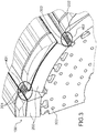
- Figure 3 represents a rotor 100 for a synchronous generator according to the present invention.
- the rotor 100 comprises a plurality of salient poles 200 regularly disposed on the outer periphery of a rim 300.
- Each salient pole 200 comprises a coil which, when circulated by an excitation current, produces a magnetic field.
- Each coil comprises two external terminals said, respectively, first terminal 201 ( figure 3 , 4 , 5 , 6 ) and second terminal 202 ( figure 3 ).
- two adjacent poles 200 are arranged to have either their respective first terminals 201 or their respective second terminals 202 facing each other.
- two adjacent salient poles 200 are arranged to have opposite polarities.
- external terminals emerge from poles in a pole interspace.
- the rotor 100 further comprises at least a first connection 401 between first terminals 201 and/or at least a second connection 402 between second terminals 202 ( figure 3 ).
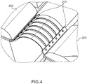
- the first connection and the second connection comprise a plurality of elongated conductive plates, advantageously not supported by the rim.
- each elongated conductive plate comprises a central section C and two ends A and B, each which are secured, with a securing means, respectively, to one and the other terminal of facing terminals.
- the first connection and/or the second connection may be flexible.
- connection can overcome some deformation when a force stemming from the rotor rotation is applied to them.
- connections having dimensions and/or mechanical properties (for example the Young Modulus) adjusted so that no breaking occurs when a force stemming from rotor rotation is applied to them.
- first connection and/or second connection may be resilient.
- connection By “resilient”, it is meant the connections can overcome some deformation, but limited to elastic deformation, when a force stemming from the rotor rotation is applied to them. In particular, it is meant connections having dimensions and/or mechanical properties (for example the Young Modulus) adjusted so that no breaking occurs when a force stemming from rotor rotation is applied to them.
- the securing means can, advantageously, be engaged through two cooperating holes made on the end of the considered elongated conductive plate and on the terminal to which said end is secured.
- the securing mean can comprise, but not limited to, a bolt/nut assembly, a screw, a rivet ( figure 6 ).
- each elongated conductive plate is made of a metal.
- the metal comprises copper or aluminum.
- a single securing mean for example a single bolt, per end for attaching the elongated conductive plate to two facing terminals improves the flexibility of the connection which is therefore less sensitive to salient poles displacement.
- connection between facing terminals is ensured by a plurality of elongated conductive plates globally reduces the effect of the mass of said connection, and, as a consequence, the sensitivity to a stress induced by the rotation of the rotor.
- the external terminals are bent or folded so as to impose a convex shape to the elongated conductive plates ( figure 5 ). This configuration further improves the flexibility of the connection means and as a consequence reduces their sensitivity to the relative displacement of the salient poles.
- the central section C of the elongated conductive plates has a reduced width with respect to the ends A and B.
- This reduced width makes it possible to create ventilation spaces between the elongated conductive plates. This ventilation limits the temperature increase due to the heating occurring during rotation of the rotor.
- the rotor can further comprise a current supply connected to two second terminals 202, said powered terminals.
- the invention also concerns a synchronous generator, in particular a synchronous hydrogenerator, which comprises the rotor according to the present invention.
Landscapes
- Engineering & Computer Science (AREA)
- Power Engineering (AREA)
- Iron Core Of Rotating Electric Machines (AREA)
- Synchronous Machinery (AREA)
- Windings For Motors And Generators (AREA)
- Control Of Eletrric Generators (AREA)
Priority Applications (4)
| Application Number | Priority Date | Filing Date | Title |
|---|---|---|---|
| CN201910694573.1A CN110784032B (zh) | 2018-07-31 | 2019-07-30 | 用于同步发电机的转子 |
| US16/526,304 US11050315B2 (en) | 2018-07-31 | 2019-07-30 | Rotor for a synchronous generator |
| KR1020190092725A KR102678954B1 (ko) | 2018-07-31 | 2019-07-30 | 동기 발전기용 로터 |
| RU2019123978A RU2019123978A (ru) | 2018-07-31 | 2019-07-30 | Ротор для синхронного генератора |
Applications Claiming Priority (1)
| Application Number | Priority Date | Filing Date | Title |
|---|---|---|---|
| EP18306041 | 2018-07-31 |
Publications (2)
| Publication Number | Publication Date |
|---|---|
| EP3605801A1 true EP3605801A1 (de) | 2020-02-05 |
| EP3605801B1 EP3605801B1 (de) | 2022-06-15 |
Family
ID=63144951
Family Applications (1)
| Application Number | Title | Priority Date | Filing Date |
|---|---|---|---|
| EP18306327.0A Active EP3605801B1 (de) | 2018-07-31 | 2018-10-08 | Rotor für einen synchrongenerator |
Country Status (7)
| Country | Link |
|---|---|
| US (1) | US11050315B2 (de) |
| EP (1) | EP3605801B1 (de) |
| KR (1) | KR102678954B1 (de) |
| CN (1) | CN110784032B (de) |
| ES (1) | ES2925389T3 (de) |
| PT (1) | PT3605801T (de) |
| RU (1) | RU2019123978A (de) |
Cited By (2)
| Publication number | Priority date | Publication date | Assignee | Title |
|---|---|---|---|---|
| CN113193675A (zh) * | 2021-05-19 | 2021-07-30 | 哈尔滨电机厂有限责任公司 | 一种水轮发电机抗变形柔性磁极间连接装置 |
| EP4604366A4 (de) * | 2022-10-13 | 2026-02-25 | Denso Corp | Wickelfeldrotor |
Citations (5)
| Publication number | Priority date | Publication date | Assignee | Title |
|---|---|---|---|---|
| JPS54144102U (de) * | 1978-03-31 | 1979-10-06 | ||
| JPS5513622A (en) * | 1978-07-12 | 1980-01-30 | Toshiba Corp | Rotor for rotary electric machine |
| JPS56110755U (de) * | 1980-01-29 | 1981-08-27 | ||
| JPS5925931U (ja) * | 1982-08-10 | 1984-02-17 | 富士電機株式会社 | 凸極回転界磁形電気機械の回転子極間接続体 |
| JPH09182340A (ja) * | 1995-12-25 | 1997-07-11 | Mitsubishi Electric Corp | 回転電機界磁コイルの極間接続装置 |
Family Cites Families (14)
| Publication number | Priority date | Publication date | Assignee | Title |
|---|---|---|---|---|
| JPS6321161Y2 (de) * | 1980-05-27 | 1988-06-10 | ||
| JPS5928852A (ja) * | 1982-08-06 | 1984-02-15 | Hitachi Ltd | 突極形回転電機 |
| US7247966B2 (en) * | 2004-06-24 | 2007-07-24 | Siemens Power Generation, Inc. | Flexible rotor pole crossover for a generator |
| RU2397104C1 (ru) * | 2009-01-12 | 2010-08-20 | Валентин Алексеевич Настасенко | Спасательная шлюпка с устройством для обеспечения ее хода и ее непрямое применение |
| JP4625147B2 (ja) * | 2009-04-13 | 2011-02-02 | パナソニック株式会社 | 同期電動機駆動システム |
| JP2012005326A (ja) | 2010-06-21 | 2012-01-05 | Aisin Seiki Co Ltd | 車両用回転電機の配線部品 |
| FR2965682B1 (fr) * | 2010-09-30 | 2012-09-21 | Valeo Equip Electr Moteur | Machine electrique tournante synchrone avec rotor a double excitation |
| JP2012100518A (ja) * | 2010-10-08 | 2012-05-24 | Denso Corp | 回転電機 |
| JP2013165589A (ja) * | 2012-02-10 | 2013-08-22 | Denso Trim Kk | 磁石式発電機 |
| JP5682600B2 (ja) * | 2012-08-07 | 2015-03-11 | トヨタ自動車株式会社 | 回転電機のロータ |
| CN103986255A (zh) * | 2013-02-07 | 2014-08-13 | 艾默生环境优化技术(苏州)有限公司 | 开关磁阻电机及其转子 |
| JP6788957B2 (ja) * | 2015-02-09 | 2020-11-25 | 株式会社シマノ | 発電機 |
| JP6241444B2 (ja) * | 2015-03-31 | 2017-12-06 | トヨタ自動車株式会社 | 磁石レス回転電機 |
| EP3079242A1 (de) * | 2015-04-10 | 2016-10-12 | Siemens Aktiengesellschaft | Herstellungsverfahren einer wicklung um einen ausspringenden pol für eine synchronmaschine |
-
2018
- 2018-10-08 EP EP18306327.0A patent/EP3605801B1/de active Active
- 2018-10-08 PT PT183063270T patent/PT3605801T/pt unknown
- 2018-10-08 ES ES18306327T patent/ES2925389T3/es active Active
-
2019
- 2019-07-30 US US16/526,304 patent/US11050315B2/en active Active
- 2019-07-30 CN CN201910694573.1A patent/CN110784032B/zh active Active
- 2019-07-30 RU RU2019123978A patent/RU2019123978A/ru unknown
- 2019-07-30 KR KR1020190092725A patent/KR102678954B1/ko active Active
Patent Citations (5)
| Publication number | Priority date | Publication date | Assignee | Title |
|---|---|---|---|---|
| JPS54144102U (de) * | 1978-03-31 | 1979-10-06 | ||
| JPS5513622A (en) * | 1978-07-12 | 1980-01-30 | Toshiba Corp | Rotor for rotary electric machine |
| JPS56110755U (de) * | 1980-01-29 | 1981-08-27 | ||
| JPS5925931U (ja) * | 1982-08-10 | 1984-02-17 | 富士電機株式会社 | 凸極回転界磁形電気機械の回転子極間接続体 |
| JPH09182340A (ja) * | 1995-12-25 | 1997-07-11 | Mitsubishi Electric Corp | 回転電機界磁コイルの極間接続装置 |
Cited By (2)
| Publication number | Priority date | Publication date | Assignee | Title |
|---|---|---|---|---|
| CN113193675A (zh) * | 2021-05-19 | 2021-07-30 | 哈尔滨电机厂有限责任公司 | 一种水轮发电机抗变形柔性磁极间连接装置 |
| EP4604366A4 (de) * | 2022-10-13 | 2026-02-25 | Denso Corp | Wickelfeldrotor |
Also Published As
| Publication number | Publication date |
|---|---|
| KR20200014239A (ko) | 2020-02-10 |
| EP3605801B1 (de) | 2022-06-15 |
| KR102678954B1 (ko) | 2024-06-26 |
| RU2019123978A (ru) | 2021-02-01 |
| US20200044506A1 (en) | 2020-02-06 |
| US11050315B2 (en) | 2021-06-29 |
| PT3605801T (pt) | 2022-08-26 |
| ES2925389T3 (es) | 2022-10-17 |
| CN110784032A (zh) | 2020-02-11 |
| CN110784032B (zh) | 2024-12-27 |
Similar Documents
| Publication | Publication Date | Title |
|---|---|---|
| EP3745559B1 (de) | Stator für eine axialflussmaschine | |
| US11050315B2 (en) | Rotor for a synchronous generator | |
| JP2003348784A (ja) | 三相磁石式発電機 | |
| JP2010011686A (ja) | 発電機およびこの発電機を備える風力発電装置 | |
| WO2017005264A1 (en) | Segmented pitch ring for a wind turbine blade pitch system | |
| EP3001542B1 (de) | Permanentmagnetrotoren | |
| US7119462B2 (en) | Generator rotor conductive path for connecting to a top-turn of a winding | |
| EP3748813A1 (de) | Permanentmagnetmodul für eine permanentmagnetmaschine | |
| WO2019053669A3 (en) | Electrical motor arrangement for electrical vehicles | |
| US20170117769A1 (en) | Rotating Electric Machine or Wind Power Generation System | |
| US7247966B2 (en) | Flexible rotor pole crossover for a generator | |
| US3246188A (en) | Amortisseur winding for synchronous machines | |
| JP2018050384A (ja) | 回転電機ステータ | |
| EP3509188B1 (de) | Elektrischer generator mit einer statorendplatte | |
| JP6752159B2 (ja) | アキシャルギャップ型回転電機 | |
| JP6613198B2 (ja) | アキシャルギャップ型回転電機 | |
| EP3934059A1 (de) | Elektrische maschine mit einem segmentierten stator oder rotor | |
| JP4640851B2 (ja) | 磁石発電機 | |
| JP3414883B2 (ja) | 回転電機界磁コイルの極間接続装置 | |
| JP3719850B2 (ja) | 回転電機の回転子コイル端部支持装置 | |
| SU843101A1 (ru) | Статор электрической машины | |
| US1545673A (en) | Damper winding | |
| JP7500808B1 (ja) | 回転電機用の回転子、および、回転電機 | |
| JP2007159256A (ja) | 回転電機 | |
| US846693A (en) | Rotating magnet for dynamo-electric machines. |
Legal Events
| Date | Code | Title | Description |
|---|---|---|---|
| PUAI | Public reference made under article 153(3) epc to a published international application that has entered the european phase |
Free format text: ORIGINAL CODE: 0009012 |
|
| STAA | Information on the status of an ep patent application or granted ep patent |
Free format text: STATUS: THE APPLICATION HAS BEEN PUBLISHED |
|
| AK | Designated contracting states |
Kind code of ref document: A1 Designated state(s): AL AT BE BG CH CY CZ DE DK EE ES FI FR GB GR HR HU IE IS IT LI LT LU LV MC MK MT NL NO PL PT RO RS SE SI SK SM TR |
|
| AX | Request for extension of the european patent |
Extension state: BA ME |
|
| STAA | Information on the status of an ep patent application or granted ep patent |
Free format text: STATUS: REQUEST FOR EXAMINATION WAS MADE |
|
| 17P | Request for examination filed |
Effective date: 20200525 |
|
| RBV | Designated contracting states (corrected) |
Designated state(s): AL AT BE BG CH CY CZ DE DK EE ES FI FR GB GR HR HU IE IS IT LI LT LU LV MC MK MT NL NO PL PT RO RS SE SI SK SM TR |
|
| STAA | Information on the status of an ep patent application or granted ep patent |
Free format text: STATUS: EXAMINATION IS IN PROGRESS |
|
| 17Q | First examination report despatched |
Effective date: 20201007 |
|
| GRAP | Despatch of communication of intention to grant a patent |
Free format text: ORIGINAL CODE: EPIDOSNIGR1 |
|
| STAA | Information on the status of an ep patent application or granted ep patent |
Free format text: STATUS: GRANT OF PATENT IS INTENDED |
|
| INTG | Intention to grant announced |
Effective date: 20220110 |
|
| GRAS | Grant fee paid |
Free format text: ORIGINAL CODE: EPIDOSNIGR3 |
|
| GRAA | (expected) grant |
Free format text: ORIGINAL CODE: 0009210 |
|
| STAA | Information on the status of an ep patent application or granted ep patent |
Free format text: STATUS: THE PATENT HAS BEEN GRANTED |
|
| AK | Designated contracting states |
Kind code of ref document: B1 Designated state(s): AL AT BE BG CH CY CZ DE DK EE ES FI FR GB GR HR HU IE IS IT LI LT LU LV MC MK MT NL NO PL PT RO RS SE SI SK SM TR |
|
| REG | Reference to a national code |
Ref country code: CH Ref legal event code: EP Ref country code: GB Ref legal event code: FG4D |
|
| REG | Reference to a national code |
Ref country code: IE Ref legal event code: FG4D |
|
| REG | Reference to a national code |
Ref country code: DE Ref legal event code: R096 Ref document number: 602018036730 Country of ref document: DE |
|
| REG | Reference to a national code |
Ref country code: AT Ref legal event code: REF Ref document number: 1498987 Country of ref document: AT Kind code of ref document: T Effective date: 20220715 |
|
| REG | Reference to a national code |
Ref country code: PT Ref legal event code: SC4A Ref document number: 3605801 Country of ref document: PT Date of ref document: 20220826 Kind code of ref document: T Free format text: AVAILABILITY OF NATIONAL TRANSLATION Effective date: 20220822 |
|
| REG | Reference to a national code |
Ref country code: LT Ref legal event code: MG9D |
|
| REG | Reference to a national code |
Ref country code: ES Ref legal event code: FG2A Ref document number: 2925389 Country of ref document: ES Kind code of ref document: T3 Effective date: 20221017 |
|
| REG | Reference to a national code |
Ref country code: NL Ref legal event code: MP Effective date: 20220615 |
|
| PG25 | Lapsed in a contracting state [announced via postgrant information from national office to epo] |
Ref country code: SE Free format text: LAPSE BECAUSE OF FAILURE TO SUBMIT A TRANSLATION OF THE DESCRIPTION OR TO PAY THE FEE WITHIN THE PRESCRIBED TIME-LIMIT Effective date: 20220615 Ref country code: NO Free format text: LAPSE BECAUSE OF FAILURE TO SUBMIT A TRANSLATION OF THE DESCRIPTION OR TO PAY THE FEE WITHIN THE PRESCRIBED TIME-LIMIT Effective date: 20220915 Ref country code: LT Free format text: LAPSE BECAUSE OF FAILURE TO SUBMIT A TRANSLATION OF THE DESCRIPTION OR TO PAY THE FEE WITHIN THE PRESCRIBED TIME-LIMIT Effective date: 20220615 Ref country code: HR Free format text: LAPSE BECAUSE OF FAILURE TO SUBMIT A TRANSLATION OF THE DESCRIPTION OR TO PAY THE FEE WITHIN THE PRESCRIBED TIME-LIMIT Effective date: 20220615 Ref country code: GR Free format text: LAPSE BECAUSE OF FAILURE TO SUBMIT A TRANSLATION OF THE DESCRIPTION OR TO PAY THE FEE WITHIN THE PRESCRIBED TIME-LIMIT Effective date: 20220916 Ref country code: FI Free format text: LAPSE BECAUSE OF FAILURE TO SUBMIT A TRANSLATION OF THE DESCRIPTION OR TO PAY THE FEE WITHIN THE PRESCRIBED TIME-LIMIT Effective date: 20220615 Ref country code: BG Free format text: LAPSE BECAUSE OF FAILURE TO SUBMIT A TRANSLATION OF THE DESCRIPTION OR TO PAY THE FEE WITHIN THE PRESCRIBED TIME-LIMIT Effective date: 20220915 |
|
| PG25 | Lapsed in a contracting state [announced via postgrant information from national office to epo] |
Ref country code: RS Free format text: LAPSE BECAUSE OF FAILURE TO SUBMIT A TRANSLATION OF THE DESCRIPTION OR TO PAY THE FEE WITHIN THE PRESCRIBED TIME-LIMIT Effective date: 20220615 Ref country code: LV Free format text: LAPSE BECAUSE OF FAILURE TO SUBMIT A TRANSLATION OF THE DESCRIPTION OR TO PAY THE FEE WITHIN THE PRESCRIBED TIME-LIMIT Effective date: 20220615 |
|
| PG25 | Lapsed in a contracting state [announced via postgrant information from national office to epo] |
Ref country code: NL Free format text: LAPSE BECAUSE OF FAILURE TO SUBMIT A TRANSLATION OF THE DESCRIPTION OR TO PAY THE FEE WITHIN THE PRESCRIBED TIME-LIMIT Effective date: 20220615 |
|
| PG25 | Lapsed in a contracting state [announced via postgrant information from national office to epo] |
Ref country code: SM Free format text: LAPSE BECAUSE OF FAILURE TO SUBMIT A TRANSLATION OF THE DESCRIPTION OR TO PAY THE FEE WITHIN THE PRESCRIBED TIME-LIMIT Effective date: 20220615 Ref country code: SK Free format text: LAPSE BECAUSE OF FAILURE TO SUBMIT A TRANSLATION OF THE DESCRIPTION OR TO PAY THE FEE WITHIN THE PRESCRIBED TIME-LIMIT Effective date: 20220615 Ref country code: RO Free format text: LAPSE BECAUSE OF FAILURE TO SUBMIT A TRANSLATION OF THE DESCRIPTION OR TO PAY THE FEE WITHIN THE PRESCRIBED TIME-LIMIT Effective date: 20220615 Ref country code: EE Free format text: LAPSE BECAUSE OF FAILURE TO SUBMIT A TRANSLATION OF THE DESCRIPTION OR TO PAY THE FEE WITHIN THE PRESCRIBED TIME-LIMIT Effective date: 20220615 Ref country code: CZ Free format text: LAPSE BECAUSE OF FAILURE TO SUBMIT A TRANSLATION OF THE DESCRIPTION OR TO PAY THE FEE WITHIN THE PRESCRIBED TIME-LIMIT Effective date: 20220615 |
|
| PG25 | Lapsed in a contracting state [announced via postgrant information from national office to epo] |
Ref country code: PL Free format text: LAPSE BECAUSE OF FAILURE TO SUBMIT A TRANSLATION OF THE DESCRIPTION OR TO PAY THE FEE WITHIN THE PRESCRIBED TIME-LIMIT Effective date: 20220615 Ref country code: IS Free format text: LAPSE BECAUSE OF FAILURE TO SUBMIT A TRANSLATION OF THE DESCRIPTION OR TO PAY THE FEE WITHIN THE PRESCRIBED TIME-LIMIT Effective date: 20221015 |
|
| REG | Reference to a national code |
Ref country code: DE Ref legal event code: R097 Ref document number: 602018036730 Country of ref document: DE |
|
| PG25 | Lapsed in a contracting state [announced via postgrant information from national office to epo] |
Ref country code: AL Free format text: LAPSE BECAUSE OF FAILURE TO SUBMIT A TRANSLATION OF THE DESCRIPTION OR TO PAY THE FEE WITHIN THE PRESCRIBED TIME-LIMIT Effective date: 20220615 |
|
| PLBE | No opposition filed within time limit |
Free format text: ORIGINAL CODE: 0009261 |
|
| STAA | Information on the status of an ep patent application or granted ep patent |
Free format text: STATUS: NO OPPOSITION FILED WITHIN TIME LIMIT |
|
| PG25 | Lapsed in a contracting state [announced via postgrant information from national office to epo] |
Ref country code: DK Free format text: LAPSE BECAUSE OF FAILURE TO SUBMIT A TRANSLATION OF THE DESCRIPTION OR TO PAY THE FEE WITHIN THE PRESCRIBED TIME-LIMIT Effective date: 20220615 |
|
| 26N | No opposition filed |
Effective date: 20230316 |
|
| PG25 | Lapsed in a contracting state [announced via postgrant information from national office to epo] |
Ref country code: SI Free format text: LAPSE BECAUSE OF FAILURE TO SUBMIT A TRANSLATION OF THE DESCRIPTION OR TO PAY THE FEE WITHIN THE PRESCRIBED TIME-LIMIT Effective date: 20220615 Ref country code: MC Free format text: LAPSE BECAUSE OF FAILURE TO SUBMIT A TRANSLATION OF THE DESCRIPTION OR TO PAY THE FEE WITHIN THE PRESCRIBED TIME-LIMIT Effective date: 20220615 |
|
| REG | Reference to a national code |
Ref country code: BE Ref legal event code: MM Effective date: 20221031 |
|
| GBPC | Gb: european patent ceased through non-payment of renewal fee |
Effective date: 20221008 |
|
| P01 | Opt-out of the competence of the unified patent court (upc) registered |
Effective date: 20230522 |
|
| PG25 | Lapsed in a contracting state [announced via postgrant information from national office to epo] |
Ref country code: LU Free format text: LAPSE BECAUSE OF NON-PAYMENT OF DUE FEES Effective date: 20221008 |
|
| PG25 | Lapsed in a contracting state [announced via postgrant information from national office to epo] |
Ref country code: BE Free format text: LAPSE BECAUSE OF NON-PAYMENT OF DUE FEES Effective date: 20221031 |
|
| PG25 | Lapsed in a contracting state [announced via postgrant information from national office to epo] |
Ref country code: IE Free format text: LAPSE BECAUSE OF NON-PAYMENT OF DUE FEES Effective date: 20221008 Ref country code: GB Free format text: LAPSE BECAUSE OF NON-PAYMENT OF DUE FEES Effective date: 20221008 |
|
| PG25 | Lapsed in a contracting state [announced via postgrant information from national office to epo] |
Ref country code: IT Free format text: LAPSE BECAUSE OF FAILURE TO SUBMIT A TRANSLATION OF THE DESCRIPTION OR TO PAY THE FEE WITHIN THE PRESCRIBED TIME-LIMIT Effective date: 20220615 |
|
| PG25 | Lapsed in a contracting state [announced via postgrant information from national office to epo] |
Ref country code: HU Free format text: LAPSE BECAUSE OF FAILURE TO SUBMIT A TRANSLATION OF THE DESCRIPTION OR TO PAY THE FEE WITHIN THE PRESCRIBED TIME-LIMIT; INVALID AB INITIO Effective date: 20181008 |
|
| PG25 | Lapsed in a contracting state [announced via postgrant information from national office to epo] |
Ref country code: CY Free format text: LAPSE BECAUSE OF FAILURE TO SUBMIT A TRANSLATION OF THE DESCRIPTION OR TO PAY THE FEE WITHIN THE PRESCRIBED TIME-LIMIT Effective date: 20220615 |
|
| PG25 | Lapsed in a contracting state [announced via postgrant information from national office to epo] |
Ref country code: MK Free format text: LAPSE BECAUSE OF FAILURE TO SUBMIT A TRANSLATION OF THE DESCRIPTION OR TO PAY THE FEE WITHIN THE PRESCRIBED TIME-LIMIT Effective date: 20220615 |
|
| PG25 | Lapsed in a contracting state [announced via postgrant information from national office to epo] |
Ref country code: TR Free format text: LAPSE BECAUSE OF FAILURE TO SUBMIT A TRANSLATION OF THE DESCRIPTION OR TO PAY THE FEE WITHIN THE PRESCRIBED TIME-LIMIT Effective date: 20220615 |
|
| REG | Reference to a national code |
Ref country code: AT Ref legal event code: UEP Ref document number: 1498987 Country of ref document: AT Kind code of ref document: T Effective date: 20220615 |
|
| PG25 | Lapsed in a contracting state [announced via postgrant information from national office to epo] |
Ref country code: MT Free format text: LAPSE BECAUSE OF FAILURE TO SUBMIT A TRANSLATION OF THE DESCRIPTION OR TO PAY THE FEE WITHIN THE PRESCRIBED TIME-LIMIT Effective date: 20220615 |
|
| PG25 | Lapsed in a contracting state [announced via postgrant information from national office to epo] |
Ref country code: BG Free format text: LAPSE BECAUSE OF FAILURE TO SUBMIT A TRANSLATION OF THE DESCRIPTION OR TO PAY THE FEE WITHIN THE PRESCRIBED TIME-LIMIT Effective date: 20220615 |
|
| PG25 | Lapsed in a contracting state [announced via postgrant information from national office to epo] |
Ref country code: BG Free format text: LAPSE BECAUSE OF FAILURE TO SUBMIT A TRANSLATION OF THE DESCRIPTION OR TO PAY THE FEE WITHIN THE PRESCRIBED TIME-LIMIT Effective date: 20220615 |
|
| PGFP | Annual fee paid to national office [announced via postgrant information from national office to epo] |
Ref country code: PT Payment date: 20250926 Year of fee payment: 8 |
|
| PGFP | Annual fee paid to national office [announced via postgrant information from national office to epo] |
Ref country code: FR Payment date: 20250925 Year of fee payment: 8 |
|
| REG | Reference to a national code |
Ref country code: CH Ref legal event code: U11 Free format text: ST27 STATUS EVENT CODE: U-0-0-U10-U11 (AS PROVIDED BY THE NATIONAL OFFICE) Effective date: 20251101 |
|
| PGFP | Annual fee paid to national office [announced via postgrant information from national office to epo] |
Ref country code: DE Payment date: 20250923 Year of fee payment: 8 |
|
| PGFP | Annual fee paid to national office [announced via postgrant information from national office to epo] |
Ref country code: AT Payment date: 20250926 Year of fee payment: 8 |
|
| PGFP | Annual fee paid to national office [announced via postgrant information from national office to epo] |
Ref country code: CH Payment date: 20251101 Year of fee payment: 8 |
|
| PGFP | Annual fee paid to national office [announced via postgrant information from national office to epo] |
Ref country code: ES Payment date: 20251103 Year of fee payment: 8 |