EP3605688B1 - Brennstoffzelle und temperatureinstellverfahren - Google Patents
Brennstoffzelle und temperatureinstellverfahren Download PDFInfo
- Publication number
- EP3605688B1 EP3605688B1 EP18771998.4A EP18771998A EP3605688B1 EP 3605688 B1 EP3605688 B1 EP 3605688B1 EP 18771998 A EP18771998 A EP 18771998A EP 3605688 B1 EP3605688 B1 EP 3605688B1
- Authority
- EP
- European Patent Office
- Prior art keywords
- temperature
- storage container
- heat medium
- fuel cell
- hydrogen
- Prior art date
- Legal status (The legal status is an assumption and is not a legal conclusion. Google has not performed a legal analysis and makes no representation as to the accuracy of the status listed.)
- Active
Links
Images


Classifications
-
- H—ELECTRICITY
- H01—ELECTRIC ELEMENTS
- H01M—PROCESSES OR MEANS, e.g. BATTERIES, FOR THE DIRECT CONVERSION OF CHEMICAL ENERGY INTO ELECTRICAL ENERGY
- H01M8/00—Fuel cells; Manufacture thereof
- H01M8/04—Auxiliary arrangements, e.g. for control of pressure or for circulation of fluids
- H01M8/04007—Auxiliary arrangements, e.g. for control of pressure or for circulation of fluids related to heat exchange
- H01M8/04029—Heat exchange using liquids
-
- H—ELECTRICITY
- H01—ELECTRIC ELEMENTS
- H01M—PROCESSES OR MEANS, e.g. BATTERIES, FOR THE DIRECT CONVERSION OF CHEMICAL ENERGY INTO ELECTRICAL ENERGY
- H01M8/00—Fuel cells; Manufacture thereof
- H01M8/04—Auxiliary arrangements, e.g. for control of pressure or for circulation of fluids
- H01M8/04082—Arrangements for control of reactant parameters, e.g. pressure or concentration
- H01M8/04201—Reactant storage and supply, e.g. means for feeding, pipes
- H01M8/04208—Cartridges, cryogenic media or cryogenic reservoirs
-
- H—ELECTRICITY
- H01—ELECTRIC ELEMENTS
- H01M—PROCESSES OR MEANS, e.g. BATTERIES, FOR THE DIRECT CONVERSION OF CHEMICAL ENERGY INTO ELECTRICAL ENERGY
- H01M8/00—Fuel cells; Manufacture thereof
- H01M8/04—Auxiliary arrangements, e.g. for control of pressure or for circulation of fluids
- H01M8/04298—Processes for controlling fuel cells or fuel cell systems
- H01M8/04313—Processes for controlling fuel cells or fuel cell systems characterised by the detection or assessment of variables; characterised by the detection or assessment of failure or abnormal function
- H01M8/0432—Temperature; Ambient temperature
- H01M8/04358—Temperature; Ambient temperature of the coolant
-
- H—ELECTRICITY
- H01—ELECTRIC ELEMENTS
- H01M—PROCESSES OR MEANS, e.g. BATTERIES, FOR THE DIRECT CONVERSION OF CHEMICAL ENERGY INTO ELECTRICAL ENERGY
- H01M8/00—Fuel cells; Manufacture thereof
- H01M8/04—Auxiliary arrangements, e.g. for control of pressure or for circulation of fluids
- H01M8/04298—Processes for controlling fuel cells or fuel cell systems
- H01M8/04313—Processes for controlling fuel cells or fuel cell systems characterised by the detection or assessment of variables; characterised by the detection or assessment of failure or abnormal function
- H01M8/0432—Temperature; Ambient temperature
- H01M8/04373—Temperature; Ambient temperature of auxiliary devices, e.g. reformers, compressors, burners
-
- H—ELECTRICITY
- H01—ELECTRIC ELEMENTS
- H01M—PROCESSES OR MEANS, e.g. BATTERIES, FOR THE DIRECT CONVERSION OF CHEMICAL ENERGY INTO ELECTRICAL ENERGY
- H01M8/00—Fuel cells; Manufacture thereof
- H01M8/04—Auxiliary arrangements, e.g. for control of pressure or for circulation of fluids
- H01M8/04298—Processes for controlling fuel cells or fuel cell systems
- H01M8/04313—Processes for controlling fuel cells or fuel cell systems characterised by the detection or assessment of variables; characterised by the detection or assessment of failure or abnormal function
- H01M8/0438—Pressure; Ambient pressure; Flow
- H01M8/04425—Pressure; Ambient pressure; Flow at auxiliary devices, e.g. reformers, compressors, burners
-
- H—ELECTRICITY
- H01—ELECTRIC ELEMENTS
- H01M—PROCESSES OR MEANS, e.g. BATTERIES, FOR THE DIRECT CONVERSION OF CHEMICAL ENERGY INTO ELECTRICAL ENERGY
- H01M8/00—Fuel cells; Manufacture thereof
- H01M8/04—Auxiliary arrangements, e.g. for control of pressure or for circulation of fluids
- H01M8/04298—Processes for controlling fuel cells or fuel cell systems
- H01M8/04694—Processes for controlling fuel cells or fuel cell systems characterised by variables to be controlled
- H01M8/04701—Temperature
- H01M8/04723—Temperature of the coolant
-
- H—ELECTRICITY
- H01—ELECTRIC ELEMENTS
- H01M—PROCESSES OR MEANS, e.g. BATTERIES, FOR THE DIRECT CONVERSION OF CHEMICAL ENERGY INTO ELECTRICAL ENERGY
- H01M8/00—Fuel cells; Manufacture thereof
- H01M8/06—Combination of fuel cells with means for production of reactants or for treatment of residues
- H01M8/0606—Combination of fuel cells with means for production of reactants or for treatment of residues with means for production of gaseous reactants
- H01M8/065—Combination of fuel cells with means for production of reactants or for treatment of residues with means for production of gaseous reactants by dissolution of metals or alloys; by dehydriding metallic substances
-
- H—ELECTRICITY
- H01—ELECTRIC ELEMENTS
- H01M—PROCESSES OR MEANS, e.g. BATTERIES, FOR THE DIRECT CONVERSION OF CHEMICAL ENERGY INTO ELECTRICAL ENERGY
- H01M8/00—Fuel cells; Manufacture thereof
- H01M8/04—Auxiliary arrangements, e.g. for control of pressure or for circulation of fluids
- H01M8/04298—Processes for controlling fuel cells or fuel cell systems
- H01M8/04694—Processes for controlling fuel cells or fuel cell systems characterised by variables to be controlled
- H01M8/04701—Temperature
- H01M8/04738—Temperature of auxiliary devices, e.g. reformer, compressor, burner
-
- Y—GENERAL TAGGING OF NEW TECHNOLOGICAL DEVELOPMENTS; GENERAL TAGGING OF CROSS-SECTIONAL TECHNOLOGIES SPANNING OVER SEVERAL SECTIONS OF THE IPC; TECHNICAL SUBJECTS COVERED BY FORMER USPC CROSS-REFERENCE ART COLLECTIONS [XRACs] AND DIGESTS
- Y02—TECHNOLOGIES OR APPLICATIONS FOR MITIGATION OR ADAPTATION AGAINST CLIMATE CHANGE
- Y02E—REDUCTION OF GREENHOUSE GAS [GHG] EMISSIONS, RELATED TO ENERGY GENERATION, TRANSMISSION OR DISTRIBUTION
- Y02E60/00—Enabling technologies; Technologies with a potential or indirect contribution to GHG emissions mitigation
- Y02E60/30—Hydrogen technology
- Y02E60/50—Fuel cells
-
- Y—GENERAL TAGGING OF NEW TECHNOLOGICAL DEVELOPMENTS; GENERAL TAGGING OF CROSS-SECTIONAL TECHNOLOGIES SPANNING OVER SEVERAL SECTIONS OF THE IPC; TECHNICAL SUBJECTS COVERED BY FORMER USPC CROSS-REFERENCE ART COLLECTIONS [XRACs] AND DIGESTS
- Y02—TECHNOLOGIES OR APPLICATIONS FOR MITIGATION OR ADAPTATION AGAINST CLIMATE CHANGE
- Y02P—CLIMATE CHANGE MITIGATION TECHNOLOGIES IN THE PRODUCTION OR PROCESSING OF GOODS
- Y02P70/00—Climate change mitigation technologies in the production process for final industrial or consumer products
- Y02P70/50—Manufacturing or production processes characterised by the final manufactured product
Definitions
- the present disclosure relates to a fuel cell, which is provided with a storage container housing hydrogen absorbing alloy and generates electricity using hydrogen as fuel, and a method of controlling the temperature in a fuel cell.
- US 2008/044704 A1 discloses a fuel cell system according to the preamble of claim 1.
- Some fuel cells react hydrogen and oxygen so as to generate electricity.
- a method that uses hydrogen absorbing alloy is known as a method of storing hydrogen.
- a fuel cell that utilizes hydrogen absorbing alloy is provided with a storage container that houses hydrogen absorbing alloy. Since a reaction that the hydrogen absorbing alloy releases hydrogen is an endothermic reaction, it is necessary to heat a storage container in order to obtain hydrogen necessary for power generation. Moreover, a reaction that hydrogen and oxygen reacts and electricity is generated is an exothermic reaction.
- International Patent Publication WO 2013/065083 discloses a fuel cell configured to heat a storage container using heat to be generated during power generation.
- a storage container is heated by circulating a heat medium between a storage container and a fuel cell stack configured to react hydrogen and oxygen so as to generate electricity.
- the present disclosure provides a fuel cell and a temperature control method that enable continuous power generation by properly controlling the temperature of storage containers.
- a fuel cell according to the present disclosure is a fuel cell characterized by comprising: a power generation unit configured to react hydrogen and oxygen so as to generate electricity; a plurality of storage containers that are detachable and house hydrogen absorbing alloy storing hydrogen to be supplied to the power generation unit; a heat medium passage through which a heat medium for heating the plurality of storage containers flows; and a temperature control unit configured to control the temperature of the heat medium, wherein the temperature control unit can carry out a first temperature control mode of controlling the temperature of the heat medium to be equal to or higher than a predetermined first temperature, and a second temperature control mode of controlling the temperature of the heat medium to be equal to or higher than a predetermined second temperature that is higher than the first temperature, and determines whether the second temperature control mode is to be carried out or not based on the pressure in a newly attached storage container or the temperature of the storage container when a new storage container is attached.
- the fuel cell according to the present disclosure comprises a plurality of storage containers that are detachable and house hydrogen absorbing alloy storing hydrogen to be supplied to the power generation unit, and heats the storage containers by causing a heat medium to flow through a heat medium passage and carrying out a first temperature control mode of controlling the temperature of the heat medium to be equal to or higher than a first temperature.
- the fuel cell can also carry out a second temperature control mode of controlling the temperature of the heat medium to be equal to or higher than a second temperature that is higher than the second temperature.
- the fuel cell determines whether the second temperature control mode is to be carried out or not based on the pressure in the newly attached storage container or the temperature of the newly attached storage container.
- the pressure in the storage container is low. It is therefore possible to estimate that the temperature of the newly attached storage container is low based on the pressure.
- the temperature of the heat medium is controlled to be a high temperature, and lack of the heat quantity of the heat medium due to a low temperature of the newly attached storage container is suppressed.
- a fuel cell according to the present disclosure is a fuel cell characterized by comprising: a power generation unit configured to react hydrogen and oxygen so as to generate electricity; a plurality of storage containers that are detachable and house hydrogen absorbing alloy storing hydrogen to be supplied to the power generation unit; a heat medium passage through which a heat medium for heating the plurality of storage containers flows; and a temperature control unit configured to heat the plurality of storage containers by controlling the temperature of the heat medium and causing the heat medium to flow through the heat medium passage, wherein the temperature control unit can carry out a first temperature control mode of controlling the temperature of the heat medium to be equal to or higher than a predetermined first temperature, and a second temperature control mode of controlling the temperature of the heat medium to be equal to or higher than a predetermined second temperature that is higher than the first temperature, and carries out the second temperature control mode when a new storage container is attached.
- the fuel cell according to the present disclosure carries out the second temperature control mode when a new storage container is attached.
- the temperature of the heat medium is controlled to be a high temperature in accordance with attachment of the new storage container, and lack of the heat quantity of the heat medium due to a low temperature of the newly attached storage container is suppressed.
- a fuel cell according to the present disclosure is a fuel cell characterized by comprising: a power generation unit configured to react hydrogen and oxygen so as to generate electricity; a plurality of storage containers that are detachable and house hydrogen absorbing alloy storing hydrogen to be supplied to the power generation unit; a heat medium passage through which a heat medium for heating the plurality of storage containers flows; and a temperature control unit configured to heat the plurality of storage containers by controlling the temperature of the heat medium and causing the heat medium to flow through the heat medium passage, wherein the temperature control unit can carry out a first temperature control mode of controlling the temperature of the heat medium to be equal to or higher than a predetermined first temperature, and a second temperature control mode of controlling the temperature of the heat medium to be equal to or higher than a predetermined second temperature that is higher than the first temperature, and determines whether the second temperature control mode is to be carried out or not based on the pressure or the temperature in an unused storage containers in a case where there is the unused storage container in the plurality of storage containers.
- the fuel cell according to the present disclosure determines whether the second temperature control mode is to be carried out or not based on the pressure or the temperature in an unused storage container in a case where there is the unused storage container. It is possible to estimate that the temperature of the storage container is low based on the pressure. By carrying out the second temperature control mode in a case where the temperature of the unused storage container is low, the temperature of the heat medium is controlled to be a high temperature, and lack of the heat quantity of the heat medium due to a low temperature of the unused storage container is suppressed.
- a temperature control method is a temperature control method, which uses a plurality of storage containers that are detachable and house hydrogen absorbing alloy storing hydrogen, and a heat medium passage through which a heat medium for heating the plurality of storage containers flows, the temperature control method being characterized by comprising steps of: controlling the temperature of the heat medium to be equal to or higher than a predetermined first temperature; heating the plurality of storage containers; controlling the temperature of the heat medium to be equal to or higher than a predetermined second temperature that is higher than the first temperature without heating an attached storage container when a new storage container is attached; and starting heating of the attached storage container after the temperature of the heat medium becomes equal to or higher than the second temperature.
- the temperature of the heat medium is controlled to be equal to or higher than the first temperature, and the plurality of storage containers are heated.
- the temperature of the heat medium is controlled to be equal to or higher than a higher second temperature without heating the attached storage container.
- heating of the attached storage container is started.
- a fuel cell and a temperature control method suppress lack of the heat quantity of the heat medium and prevent lowering of the temperature of the other storage container when a new storage container is attached or in a case where there is an unused storage container. This exhibits excellent effects that lowering of the hydrogen pressure is prevented and that a fuel cell can execute continuous power generation, and the like.
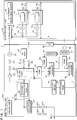
- a fuel cell 1 drawn in FIG. 1 is a fuel cell such as a polymer electrolyte fuel cell, for example, and reacts hydrogen and oxygen so as to generate electricity.
- the fuel cell 1 is provided with a main fuel cell unit 100 and a hydrogen supply unit 110.
- the main fuel cell unit 100 is provided with a fuel cell stack 10, a control unit 11, a hydrogen flow passage 2, an air flow passage 3, a stack coolant passage 4, a radiator passage 5, and a heat medium passage 6.
- the hydrogen flow passage 2 includes a hydrogen supply passage 2a and a hydrogen circulation passage 2b.
- the control unit 11 is connected with the respect components of the fuel cell 1.
- the control unit 11 is provided with a CPU (Central Processing Unit) configured to control operations of the respective components, and a storage unit configured to store an operation program of the fuel cell 1. It is to be noted that connection of the control unit 11 and each component is omitted in FIG. 1 .
- CPU Central Processing Unit
- the fuel cell stack 10 is prepared by sandwiching a solid polymer electrolyte membrane with a negative electrode and a positive electrode from both sides so as to form a membrane electrode assembly, arranging a pair of separators on both sides of the membrane electrode assembly so as to construct a tabular unit cell, and laminating and packaging a plurality of such unit cells.
- fuel gas including hydrogen which has flown in through the hydrogen flow passage 2 comes into contact with the negative electrode, and oxidant gas including oxygen such as air from the air flow passage 3 flows into and comes into contact with the positive electrode, an electrochemical reaction occurs at both electrodes, and electromotive force is generated.
- the fuel cell stack 10 corresponds to a power generation unit according to the present disclosure.
- the hydrogen supply passage 2a is a flow passage through which hydrogen to be supplied from the hydrogen supply unit 110 to the fuel cell stack 10 flows.
- One end portion of the hydrogen supply passage 2a is connected with the hydrogen supply unit 110, while the other end portion is connected with a part of the hydrogen circulation passage 2b close to the negative electrode of the fuel cell stack 10.
- a pressure sensor 21, an on-off valve 23, an on-off valve 24, and a check valve 25 are provided in this order from the hydrogen supply unit 110 side.
- the hydrogen circulation passage 2b is a flow passage through which hydrogen discharged from the fuel cell stack 10 is circulated to the fuel cell stack 10.
- the hydrogen circulation passage 2b is provided with a hydrogen circulation pump 26 and a gas-liquid separator 27.
- the gas-liquid separator 27 is coupled with an air discharge valve 261 and an air discharge valve 262, and with a water discharge valve 271 and a water discharge valve 272.
- the on-off valve 23, the on-off valve 24, the air discharge valve 261, the air discharge valve 262, the water discharge valve 271, and the water discharge valve 272 are electromagnetic valves that can be controlled by the control unit 11 to be in an open state and a close state, and more preferably are normally closed electromagnetic valves.
- hydrogen flows from the hydrogen supply unit 110 through the on-off valve 23, the on-off valve 24, the check valve 25, and the hydrogen supply passage 2a. Furthermore, hydrogen is caused by the hydrogen circulation pump 26 to flow through the hydrogen circulation passage 2b, is delivered to the negative electrode side part of the fuel cell stack 10, and flows through a flow passage in the negative electrode side part. Hydrogen, which has flown through the flow passage and has been discharged from the fuel cell stack 10, flows through the hydrogen circulation passage 2b and is delivered to the gas-liquid separator 27. The gas-liquid separator 27 separates water and gas including hydrogen and impurities. Separated gas is delivered from the gas-liquid separator 27 to the hydrogen circulation pump 26 and is circulated through the hydrogen circulation passage 2b.
- the water discharge valve 271 and the water discharge valve 272 are opened, so that the water is discharged to outside.
- the air discharge valve 261 and the air discharge valve 262 are opened with proper timing, so that gas including impurities is discharged to outside.
- the air flow passage 3 is a passage through which air to be supplied to the fuel cell stack 10 flows.
- the air flow passage 3 is provided with an air pump 30.
- the air pump 30 takes air in and supplies air to the fuel cell stack 10 through the air flow passage 3.
- An on-off valve 31 is provided between the air pump 30 and the fuel cell stack 10.
- An on-off valve 32 is provided at a part through which air flows out of the fuel cell stack 10. When the on-off valve 31 and the on-off valve 32 are opened, air delivered from the air pump 30 flows through the air flow passage 3 and the on-off valve 31, is introduced to a positive electrode side part of the fuel cell stack 10, and flows through a flow passage in the positive electrode side part. Air which has flown through the flow passage is discharged from the fuel cell stack 10 and is discharged to outside through the on-off valve 32.
- the stack coolant passage 4 is a flow passage through which cooling water for cooling the fuel cell stack 10 flows and is circulated. It is to be noted that a heat medium (e.g., ethylene glycol) other than water may be used for cooling the fuel cell stack 10.
- a pump 40, a first heat exchanger 41, a second heat exchanger 42, an ion exchange resin 43, and a conductivity meter 44 are provided in the middle of the stack coolant passage 4.
- the pump 40 circulates cooling water through the stack coolant passage 4 so as to cool the fuel cell stack 10. Cooling water which flows through the stack coolant passage 4 is introduced by the pump 40 to the fuel cell stack 10 and flows through a flow passage in the fuel cell stack 10.
- Cooling water which has flown through the flow passage in the fuel cell stack 10 is delivered from the pump 40, flows through the first heat exchanger 41, the second heat exchanger 42, the ion exchange resin 43, and the conductivity meter 44, and is introduced again to the fuel cell stack 10.
- the ion exchange resin 43 removes ions included in cooling water.
- the conductivity meter 44 measures the conductivity of the cooling water.
- the radiator passage 5 is a flow passage through which heat radiation liquid for radiating heat of cooling water passing through the first heat exchanger 41 flows and is circulated.
- the radiator passage 5 is coupled with the first heat exchanger 41.
- the radiator passage 5 is provided with a pump 50 and a radiator 51.
- the pump 50 circulates the heat radiation liquid through the radiator passage 5 so as to radiate heat of cooling water passing through the first heat exchanger 41.
- Heat radiation liquid delivered from the pump 50 flows through the first heat exchanger 41 and the radiator 51 and returns to the pump 50.
- An example of heat radiation liquid is antifreeze composed mainly of ethylene glycol.
- a fan 52 is provided in proximity to the radiator 51. Heat of cooling water is conducted to the heat radiation liquid in the first heat exchanger 41. Wind delivered from the fan 52 blows against the radiator 51, and heat of the heat radiation liquid passing through the radiator 51 is radiated. Heat of cooling water is radiated in such a manner.
- the heat medium passage 6 is a flow passage through which a heat medium flows and is circulated.
- the heat medium is fluid and is, for example, water or antifreeze (e.g., ethylene glycol).
- the heat medium passage 6 is coupled with the second heat exchanger 42.
- the heat medium passage 6 is provided with a pump 60, a heater 61, and a temperature sensor 62.
- the heat medium passage 6 is provided to extend through both of the main fuel cell unit 100 and the hydrogen supply unit 110.
- the heat medium passage 6 has a plurality of branch passages 63, and on-off valves 64 configured to open and close the respective branch passages 63.
- the branch passages 63 and the on-off valves 64 are provided in the hydrogen supply unit 110.
- the pump 60 circulates a heat medium through the heat medium passage 6.
- heat is conducted from cooling water to a heat medium.
- the heater 61 heats the heat medium.
- the temperature sensor 62 measures the temperature of the heat medium.
- the on-off valves 64 are electromagnetic valves that can be controlled by the control unit 11 to be in an open state and a close state, and more preferably are normally closed electromagnetic valves.
- the hydrogen supply unit 110 is provided with a regulator 22 and a plurality of hydrogen storage units 70.
- the regulator 22 is connected with one end portion of the hydrogen supply passage 2a.
- the plurality of hydrogen storage units 70 house a plurality of storage containers 71 housing hydrogen absorbing alloy that stores hydrogen.
- FIG. 1 illustrates an example in which two hydrogen storage units 70 are provided, the hydrogen supply unit 110 may be provided with three or more hydrogen storage units 70.
- one hydrogen storage unit 70 may house a plurality of storage containers 71.
- Each hydrogen storage unit 70 is attachable to and detachable from the hydrogen supply unit 110.
- a storage container 71 is attached to or detached from the hydrogen supply unit 110.
- Each storage container 71 houses hydrogen absorbing alloy.
- Each storage container 71 is configured to conduct external heat to the hydrogen absorbing alloy.
- the plurality of hydrogen storage units 70 are in proximity to, in contact with, or coupled with the plurality branch passages 63.
- Each hydrogen storage unit 70 is configured to conduct heat of a heat medium passing through a branch passage 63 to a storage container 71.
- each hydrogen storage unit 70 is a box, and a heat transfer material or a heat transfer mechanism is provided between the branch passage 63 and the storage container 71 which are in proximity to, in contact with, or coupled with each other.
- a structure in which each branch passage 63 extends through a hydrogen storage unit 70 and the branch passage 63 is in contact with a storage container 71 may be employed.
- Each storage container 71 is coupled with a pressure sensor 72 and a hydrogen supply valve 73.
- Each pressure sensor 72 measures the pressure in a storage container 71.
- the pressure sensors 72 correspond to a detector according to the present disclosure.
- the hydrogen supply valves 73 are connected with a hydrogen supply passage 74.
- the hydrogen supply valves 73 are electromagnetic valves that can be controlled by the control unit 11 to be in an open state and a close state, and more preferably are normally closed electromagnetic valves.
- the hydrogen supply passage 74 is connected with the regulator 22. In a state where a hydrogen storage unit 70 is detached from the hydrogen supply unit 110, a hydrogen supply valve 73 is closed. In a state where a hydrogen storage unit 70 is attached to the hydrogen supply unit 110, a hydrogen supply valve 73 is opened.
- a hydrogen supply valve 73 In a state where a hydrogen supply valve 73 is opened, it becomes possible to supply hydrogen from a storage container 71 through a hydrogen supply passage 74 and the regulator 22 to the main fuel cell unit 100.
- the pressure sensors 72 are located upstream the hydrogen supply valves 73 in the flow of hydrogen from the storage containers 71 to the main fuel cell unit 100.
- the pressure sensors 72 and the hydrogen supply valves 73 may be fixed to the hydrogen supply passage 74, or may be fixed to the hydrogen storage units 70 so as to be attachable to and detachable from the hydrogen supply unit 110 together with the hydrogen storage units 70.
- the hydrogen supply unit 110 is further provided with an attachment/detachment sensor 75 configured to detect attachment or detachment of the plurality of storage containers 71.
- the attachment/detachment sensor 75 is a sensor configured to detect the operation of an unillustrated opening/closing mechanism provided at a connection part of each storage container 71 and each hydrogen supply passage 74.
- the attachment/detachment sensor 75 may be an input switch to be operated by a user who manually attaches or detaches a hydrogen storage unit 70 so as to input attachment or detachment of a storage container 71.
- the heat medium is heated by the second heat exchanger 42 and the heater 61 and is caused by the pump 60 to flow through the heat medium passage 6.
- the heat medium flows through the branch passages 63, heat is conducted from the heat medium to the storage containers 71, and the storage containers 71 are heated.
- a storage container 71 is selectively heated by causing the heat medium to flow selectively through any one branch passage 63.
- hydrogen absorbing alloy housed in the storage container 71 is heated, and hydrogen is released from the hydrogen absorbing alloy.
- the released hydrogen flows from the storage container 71 through a hydrogen supply passage 74, the regulator 22, and the hydrogen flow passage 2, and is supplied to the fuel cell stack 10.
- the regulator 22 controls the hydrogen supply pressure. When hydrogen is supplied to the fuel cell stack 10, the fuel cell stack 10 generates electricity.
- the fuel cell 1 continuously generates electricity by sequentially replacing storage containers 71 in which hydrogen has been consumed.
- a storage container 71 is replaced by replacing a hydrogen storage unit 70.
- the control unit 11 performs processing to heat the storage containers 71 so that electricity is continuously generated.
- the processing to heat the storage containers 71 will be described.
- the following description will illustrate a fuel cell 1 provided with two hydrogen storage units 70 as an example of the fuel cell 1.
- One of the two hydrogen storage units 70 will be expressed as a hydrogen storage unit (A) 70, while the other will be expressed as a hydrogen storage unit (B) 70.
- One of the storage containers 71, the pressure sensors 72, the branch passages 63, and the on-off valves 64 will be expressed as a storage container (A) 71, a pressure sensor (A) 72, a branch passage (A) 63, and an on-off valve (A) 64, while the other will be expressed as a storage container (B) 71, a pressure sensor (B) 72, a branch passage (B) 63, and an on-off valve (B) 64.
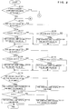
- FIGS. 2 and 3 are a flowchart illustrating the process procedures of heating a storage container 71 in Embodiment 1.
- the control unit 11 determines whether a new storage container 71 has been attached or not according to the detection result of the attachment/detachment sensor 75 (S101).
- S101 attachment/detachment sensor 75
- a hydrogen storage unit 70 is replaced, a storage container 71 is replaced, and attachment of a new storage container 71 is detected.
- any hydrogen storage unit 70 has not been replaced.
- the control unit 11 determines whether the on-off valve (A) 64 is closed or not (S102). In a case where the on-off valve (A) 64 is closed (S102: YES), the control unit 11 determines whether or not a pressure P(A) measured by the pressure sensor (A) 72 is equal to or lower than a predetermined pressure H1, or determines whether or not a temperature T of a heat medium measured by the temperature sensor 62 is equal to or lower than a predetermined temperature T1 (S103). In a state where the on-off valve 64 is closed, heating of the storage container 71 by flow of the heat medium through the branch passage 63 is not performed.
- the pressure H1 is a threshold to be used for determining that the hydrogen pressure in the storage container 71 is sufficient and not heating the storage container 71 in a case where the pressure in the storage container 71 exceeds the pressure H1.
- the pressure H1 is 170 kPa, for example.
- the temperature T1 is a threshold to be used for circulating the heat medium in a case where the temperature T of the heat medium is equal to or lower than the temperature T1.
- the temperature T1 is 40 °C, for example.
- the control unit 11 opens the on-off valve (A) 64 (S104). Flow of the heat medium through the branch passage (A) 63 becomes possible, and heating of the storage container (A) 71 becomes possible. Next, the control unit 11 proceeds with the processing to S107. In a case where the pressure P(A) exceeds the pressure H1 and the temperature T of the heat medium exceeds the temperature T1 (S103: NO), the control unit 11 proceeds with the processing to S107.
- the on-off valve (A) 64 is kept close, and heating of the storage container (A) 71 by flow of the heat medium through the branch passage (A) 63 is not performed.
- the control unit 11 determines whether the pressure P(A) is equal to or higher than a predetermined pressure H2 and the temperature T of the heat medium is equal to or higher than a predetermined temperature T2 or not (S105). In a state where the on-off valve 64 is opened, heating of the storage container 71 by flow of the heat medium through the branch container 63 can be performed.
- the pressure H2 is a threshold to be used for determining that the hydrogen pressure in the storage container 71 is insufficient and heating the storage container 71 in a case where the pressure in the storage container 71 is lower than the pressure H2.
- the pressure H2 is 200 kPa, for example.
- the temperature T2 is a threshold to be used for not circulating the heat medium in a case where the temperature T of the heat medium is equal to or higher than the temperature T2.
- the temperature T2 is 45 °C, for example.
- the control unit 11 closes the on-off valve (A) 64 (S106). Heating of the storage container (A) 71 by flow of the heat medium through the branch passage (A) 63 is stopped. Next, the control unit 11 proceeds with the processing to S107. In a case where the pressure P(A) is lower than the pressure H2 or the temperature T of the heat medium is lower than the temperature T2 (S105: NO), the control unit 11 proceeds with the processing to S107.
- the on-off valve (A) 64 is kept open, and heating of the storage container (A) 71 by flow of the heat medium through the branch passage (A) 63 can be performed.
- the control unit 11 determines whether the on-off valve (B) 64 is closed or not (S107). In a case where the on-off valve (B) 64 is closed (S107: YES), the control unit 11 determines whether or not a pressure P(B) measured by the pressure sensor (B) 72 is equal to or lower than the pressure H1 or the temperature T of the heat medium is equal to or lower than the temperature T1 (S108).
- the control unit 11 opens the on-off valve (B) 64 (S109). Flow of the heat medium through the branch passage (B) 63 becomes possible, and heating of the storage container (B) 71 becomes possible.
- the control unit 11 proceeds with the processing to S112.
- the control unit 11 proceeds with the processing to S112.
- the on-off valve (B) 64 is kept close, and heating of the storage container (B) 71 by flow of the heat medium through the branch passage (B) 63 is not performed.
- the control unit 11 determines whether or not the pressure P(B) is equal to or higher than the pressure H2 and the temperature T of the heat medium is equal to or higher than the pressure T2 (S110). In a case where the pressure P(B) is equal to or higher than the pressure H2 and the temperature T of the heat medium is equal to or higher than the pressure T2 (S110: YES), the control unit 11 closes the on-off valve (B) 64 (S111). Heating of the storage container (B) 71 by flow of the heat medium through the branch passage (B) 63 is stopped. Next, the control unit 11 proceeds with the processing to S112.
- the control unit 11 proceeds with the processing to S112.
- the on-off valve (B) 64 is kept open, and heating of the storage container (B) 71 by flow of the heat medium through the branch passage (B) 63 becomes possible.
- the control unit 11 determines whether the on-off valve (A) 64 or the on-off valve (B) 64 is opened or not (S112). In a case where the on-off valve (A) 64 or the on-off valve (B) 64 is opened (S112: YES), the control unit 11 causes the pump 60 to operate (S113). In a case where the pump 60 is in operation, the pump 60 is kept in operation. Operation of the pump 60 circulates the heat medium through the heat medium passage 6. In a case where the on-off valve (A) 64 and the on-off valve (B) 64 are closed (S112: NO), the control unit 11 stops the pump 60 (S114). In a case where the pump 60 is out of operation, the pump 60 is kept out of operation.
- the control unit 11 determines whether or not the temperature T of the heat medium is equal to or higher than a predetermined T3 (S115).
- the temperature T3 is a threshold to be used for heating the heat medium in a case where the temperature T of the heat medium is lower than the temperature T3.
- the temperature T3 is 23 °C, for example.
- the control unit 11 stops the heater 61 (S116). In a case where the heater 61 is out of operation, the heater 61 is kept out of operation.
- the control unit 11 causes the heater 61 to operate (S117). In a case where the heater 61 is in operation, the heater 61 is kept in operation. The operation of the heater 61 heats the heat medium. After S116 or S117 is finished, the control unit 11 terminates the processing. Next, the control unit 11 repeats the processing from S101.
- Heat generated from the fuel cell stack 10 is conducted to the heat medium in the second heat exchanger 42, and the heat medium is heated by the heater 61.
- the processes of S102 to S117 control the temperature of the heat medium to be equal to or higher than a predetermined temperature T3.
- the temperature T3 corresponds to a first temperature according to the present disclosure.
- the control unit 11, the fuel cell stack 10, the second heat exchanger 42, the pump 60, the heater 61, and the temperature sensor 62 are included in a temperature control unit according to the present disclosure.
- the processes of S102 to S117 correspond to a first temperature control mode. In a case where the on-off valve (A) 64 is opened, the heat medium flows through the branch passage (A) 63, and the storage container (A) 71 is heated.
- the on-off valve (B) 64 is opened, the heat medium flows through the branch passage (B) 63, and the storage container (B) 71 is heated. In such a manner, the storage container 71 is heated, the hydrogen absorbing alloy in the storage container 71 is heated, hydrogen is released, and released hydrogen is supplied to the fuel cell stack 10.
- the control unit 11 performs processes similar to S101 to S117.
- the control unit 11 executes processes similar to the processes of S102 to S106 and the processes of S107 to S111 for each of the storage containers 71.
- the control unit 11 executes the process of S113 in a case where any one on-off valve 64 is opened, or executes the process of S114 in a case where all on-off valves 64 are closed.
- the control unit 11 When a new storage container 71 is attached, the control unit 11 performs processing for heating the attached storage container 71.
- the attachment/detachment sensor 75 detects that a new storage container 71 has been attached. Moreover, the attachment/detachment sensor 75 specifies the newly attached storage container 71.
- the hydrogen storage unit (A) 70 is not replaced and the hydrogen storage unit (B) 70 is replaced. That is, assume that the storage container (A) 71 is not replaced and a storage container (B) 71 is newly attached.
- the control unit 11 determines whether or not the pressure P(B) measured by the pressure sensor (B) 72 is equal to or higher than a predetermined pressure H3 (S21).
- the pressure H3 is a threshold to be used for determining that the hydrogen pressure in the storage container 71 is sufficient and not performing following processing for controlling the temperature of the heat medium in a case where the pressure in the newly attached storage container 71 is equal to or higher than the pressure H3.
- the pressure H3 is 100 kPa, for example. In a case where the pressure P(B) is equal to or higher than the pressure H3 (S21: YES), the control unit 11 proceeds with the processing to S102.
- the control unit 11 closes the on-off valve (B) 64 (S22). In a case where the on-off valve (B) 64 is closed, the on-off valve (B) 64 is kept close. Next, the control unit 11 opens the on-off valve (A) 64 (S23). In a case where the on-off valve (A) 64 is opened, the on-off valve (A) 64 is kept open. Next, the control unit 11 causes the pump 60 to operate (S24). In a case where the pump 60 is in operation, the pump 60 is kept in operation. Next, the control unit 11 causes the heater 61 to operate (S25). In a case where the heater 61 is in operation, the heater 61 is kept in operation. The heat medium is heated in a state where the heat medium does not flow through the branch passage (B) 63 but flows through the branch passage (A) 63.
- the control unit 11 determines whether or not the temperature T of the heat medium is equal to or higher than a predetermined temperature T4 (S26).
- the temperature T4 is a target temperature for controlling the temperature T of the heat medium to be equal to or higher than the temperature in a state where the heat medium does not flow through the branch passage (B) 63.
- the temperature T4 is a temperature higher than the temperature T3.
- the temperature T4 is 40 °C, for example.
- the control unit 11 repeats the process of S26 until the temperature T of the heat medium becomes equal to or higher than the predetermined temperature T4.
- the control unit 11 proceeds with the processing to S102.
- a state where the pressure P(B) in a newly attached storage container (B) 71 is lower than the pressure H3 is a state where the storage container (B) 71 has not been heated, the temperature of the hydrogen absorbing alloy in the storage container (B) 71 is low, and the hydrogen cannot be released sufficiently.
- the storage container (B) 71 is not heated in a case where the pressure P(B) in the storage container (B) 71 is lower than the pressure H3.
- the heat medium is heated, and the temperature T of the heat medium is controlled to be equal to or higher than the temperature T4.
- the temperature T4 corresponds to a second temperature according to the present disclosure.
- the processes of S22 to S26 correspond to a second temperature control mode. After the temperature T of the heat medium becomes equal to or higher than the temperature T4, the second temperature control mode is finished, and the processing from S102, that is, the first temperature control mode is executed. In such a manner, the newly attached storage container (B) 71 is heated after the temperature of the heat medium is controlled to be a temperature equal to or higher than the temperature T4.
- control unit 11 carries out processes similar to S21 to S26. In S23, the control unit 11 opens on-off valves 64 except the on-off valve (B) 64 related to a newly attached storage container (B) 71.
- the fuel cell 1 in this embodiment heats a plurality of storage containers 71 by carrying out the first temperature control mode (processes of S102 to S117) of controlling the temperature T of the heat medium to be equal to or higher than the temperature T3.
- the fuel cell 1 can also carry out the second temperature control mode (processes of S22 to S26) of controlling the temperature T of the heat medium to be equal to or higher than the temperature T4 that is higher than the temperature T3.
- the fuel cell 1 determines whether the second temperature control mode is to be carried out or not based on the pressure in the attached storage container 71.
- the fuel cell 1 carries out the second temperature control mode in a case where the pressure in the attached storage container 71 is lower than the pressure H3.
- the temperature of a newly attached storage container 71 may possibly become extremely lower than the other storage container 71.
- the temperature of the heat medium lowers, and the heat medium lacks the heat quantity for heating the other storage container 71. Lack of the heat quantity lowers the temperature of the other storage container 71, the temperature of the hydrogen absorbing alloy lowers, the hydrogen pressure lowers, and power generation in the fuel cell stack 10 may possibly become difficult.
- the temperature of the hydrogen absorbing alloy therein is also low, and the pressure in the storage container 71 is low.
- the temperature of the storage container 71 is low based on the pressure in the storage container 71.
- a case where the pressure in an attached storage container 71 is lower than the pressure H3 is a case where the temperature of the storage container 71 is low.
- the temperature of the heat medium is controlled to be a temperature (e.g., equal to or higher than the temperature T4) exceeding the temperature T3, and lowering of the temperature of the heat medium due to a low temperature of an attached storage container 71 is suppressed.
- the fuel cell 1 can execute continuous power generation.
- the fuel cell 1 in this embodiment carries out the second temperature control mode (processes of S22 to S26), finishes the second temperature control mode when the temperature T of the heat medium becomes equal to or higher than the temperature T4, and carries out the first temperature control mode (processes of S102 to S117).
- the fuel cell 1 does not heat a newly attached storage container 71 in the second temperature control mode but heats an attached storage container 71 in the first temperature control mode. That is, the fuel cell 1 starts heating of a newly attached storage container 71 after the temperature T of the heat medium is controlled to be equal to or higher than the temperature T4.
- the fuel cell 1 in this embodiment carries out the second temperature control mode in a state where the on-off valve 64 configured to open and close a branch passage 63 for heating a newly attached storage container 71 is closed while the on-off valve 64 configured to open and close the branch passage 63 for heating the other storage container 71 is opened, in the processes of S22 to S26.
- the fuel cell 1 does not heat a newly attached storage container 71 when carrying out the second temperature control mode.
- the on-off valve 64 related to the other storage container 71 is opened, the heat medium is circulated through the heat medium passage 6, and the heat medium is heated as a whole by the second heat exchanger 42 and the heater 61.
- the fuel cell 1 in this embodiment is provided with the pressure sensor 71, and determines whether the second temperature control mode is to be carried out or not based on the pressure in the storage container 71 measured by the pressure sensor 72.
- the fuel cell 1 can select a proper temperature control method for the heat medium according to the state of a newly attached storage container 71 based on the measurement result of the pressure sensor 72.
- the pressure sensor 72 in this embodiment is disposed upstream the hydrogen supply valve 73. Therefore, the pressure sensor 72 can measure the pressure in the storage container 71 even in a state where the hydrogen supply passage 73 is closed and hydrogen is not supplied from the storage container 71.
- the fuel cell 1 may have an aspect in which a temperature sensor configured to measure the temperature of the storage containers 71 is provided as a detector.
- the fuel cell 1 determines whether the second temperature control mode is to be carried out or not based on the temperature of the storage container 71 measured by the temperature sensor.
- the temperature sensor measures the temperature of a newly attached storage container 71, and the control unit 11 in S21 proceeds with the processing to S22 in a case where the measured temperature is equal to or higher than a predetermined temperature T5, or proceeds with the processing to S102 in a case where the measured temperature is lower than the temperature T5.
- the temperature T5 is a threshold to be used for carrying out the second temperature control mode in a case where the temperature of the attached storage container 71 is lower than the temperature T5.
- the fuel cell 1 carries out the second temperature control mode in a case where the temperature of the attached storage container 71 is low, lack of the heat quantity of the heat medium is suppressed, and lowering of the temperature of the other storage container 7 can be prevented.
- the fuel cell 1 may have an aspect in which both of the pressure sensor 72 and the temperature sensor are provided, and whether the second temperature control mode is to be carried out or not is determined based on the measurement results of the pressure sensor 72 and the temperature sensor.
- the fuel cell 1 may have an aspect in which a temperature control circuit for controlling the temperature of the heat medium is provided separately from the control unit 11.
- the control unit 11 controls the temperature control circuit
- the temperature control circuit controls the pump 60, the heater 61, and a plurality of on-off valves 64.
- the temperature control circuit is included in a temperature control unit according to the present disclosure.
- the fuel cell 1 may have an aspect in which the heat medium passage 6 is further provided with a heat radiation mechanism such as a radiator.
- control unit 11 or the temperature control circuit may perform processing of controlling the temperature of the heat medium to be equal to or lower than a predetermined upper limit temperature in the first temperature control mode by radiating the heat of the heat medium using the heat radiation mechanism.
- the heat radiation mechanism is included in a temperature control unit according to the present disclosure.
- the fuel cell 1 may have an aspect in which attachment of a storage container 71 is detected without using the attachment/detachment sensor 75.
- the fuel cell 1 may have an aspect in which attachment of a new storage container 71 is detected based on the measurement result of the pressure sensor 72 or a temperature sensor configured to measure the temperature of the storage container 71 becoming a specific value, or the time variation of the measurement result indicating a specific variation.
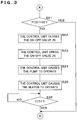
- FIG. 4 is a flowchart illustrating partial process procedures in Embodiment 2. Processing of this embodiment will also be described assuming that a storage container (A) 71 is not replaced, and a storage container (B) 71 is newly attached. In a case where a new storage container 71 has been attached in S101 (S101: YES), the control unit 11 closes an on-off valve (B) 64 (S31). In a case where the on-off valve (B) 64 is closed, the on-off valve (B) 64 is kept close.
- the control unit 11 opens an on-off valve (A) 64 (S32). In a case where the on-off valve (A) 64 is opened, the on-off valve (A) 64 is kept open.
- the control unit 11 causes the pump 60 to operate (S33). In a case where the pump 60 is in operation, the pump 60 is kept in operation.
- the control unit 11 causes the heater 61 to operate (S34). In a case where the heater 61 is in operation, the heater 61 is kept in operation.
- the heat medium is heated in a state where the heat medium does not flow through the branch passage (B) 63 but flows through the branch passage (A) 63.
- the control unit 11 determines whether the temperature T of the heat medium is equal to or higher than a predetermined temperature T4 or not (S35). In a case where the temperature T of the heat medium is lower than the temperature T4 (S35: NO), the control unit 11 repeats the process of S35 until the temperature T of the heat medium becomes equal to or higher than the predetermined temperature T4. In a case where the temperature T of the heat medium is equal to or higher than the temperature T4 (S35: YES), the control unit 11 proceeds with the processing to S102. Even in an aspect in which the fuel cell 1 is provided with three or more storage containers 71, the control unit 11 performs processes similar to S31 to S35. In S32, the control unit 11 opens on-off valves 64 except the on-off valve (B) 64 related to a newly attached storage container (B) 71.
- the processes of S31 to S35 in this embodiment correspond to the second temperature control mode according to the present disclosure.
- the fuel cell 1 in this embodiment carries out the second temperature control mode when a new storage container 71 is attached.
- the temperature of a newly attached storage container 71 is likely to be lower than the other storage container 71. Since the second temperature control mode of controlling the temperature of the heat medium to be a temperature exceeding the temperature T3 is immediately carried out, lowering of the temperature of the heat medium due to a low temperature of the attached storage container 71 is suppressed, and lack of the heat quantity of the heat medium for heating the other storage container 71 is suppressed.
- the fuel cell 1 according to this embodiment can execute continuous power generation.
- the fuel cell 1 in this embodiment carries out the second temperature control mode (processes of S31 to S35), finishes the second temperature control mode in a case where the temperature T of the heat medium becomes equal to or higher than the temperature T4, and carries out the first temperature control mode (processes of S102 to S117).
- the fuel cell 1 does not heat a newly attached storage container 71 in the second temperature control mode but heats the attached storage container 71 in the first temperature control mode. That is, the fuel cell 1 starts heating of a newly attached storage container 71 after controlling the temperature T of the heat medium to be equal to or higher than the temperature T4.
- the fuel cell 1 in this embodiment carries out the second temperature control mode in a state where an on-off valve 64 configured to open and close a branch passage 63 for heating a newly attached storage container 71 is closed while the on-off valve 64 configured to open and close the branch passage 63 for heating the other storage container 71 is opened.
- the fuel cell 1 carries out the second temperature control mode without heating a newly attached storage container 71.
- the heat medium passes through the on-off valve 64 related to the other storage container 71, is circulated through the heat medium passage 6, and is heated as a whole.
- FIG. 5 is a flowchart illustrating partial process procedures in Embodiment 3.
- the control unit 11 determines whether there is an unused storage container 71 in a plurality of storage containers 71 or not (S401).
- an unused storage container 71 is a storage container 71 which has been newly attached by replacement of the hydrogen storage unit 70.
- the control unit 11 determines whether a new storage container 71 has been attached or not according to the detection result of the attachment/detachment sensor 75.
- an unused storage container 71 is, for example, a storage container 71 which is provided in the fuel cell 1 in advance and has never been used for supply of hydrogen. In a case where such an unused storage container 71 is used for the first time, the control unit 11 determines that there is an unused storage container 71.
- a storage container 71 housed in a hydrogen storage unit 70 provided in a hydrogen supply unit 110 used for replacement is an unused storage container 71.
- the control unit 11 determines that there is an unused storage container 71 according to detection of replacement of a hydrogen supply unit 110.
- a storage container 71 included in the replaced part for example, is an unused storage container 71.
- the control unit 11 determines that there is an unused storage container 71 according to detection of replacement.
- a storage container 71 housed in the added hydrogen storage unit 70 for example, is an unused storage container 71.
- the control unit 11 determines that there is an unused storage container 71 according to detection of addition.
- control unit 11 executes the processes of S102 to S117 as with Embodiment 1. After the process of S116 or S117 is finished, the control unit 11 terminates the processing. Next, the control unit 11 repeats the processing from S401. In a case where there is an unused storage container 71 (S401: YES), the control unit 11 executes the processes of S21 to S26 as with Embodiment 1 assuming that an unused storage container 71 is a storage container (B) 71 while the other storage container 71 is a storage container (A) 71.
- the fuel cell 1 in this embodiment determines whether the second temperature control mode is to be carried out or not based on the pressure in an unused storage container 71 in a case where there is an unused storage container 71.
- the fuel cell 1 carries out the second temperature control mode in a case where the pressure in an unused storage container 71 is lower than a predetermined pressure H3.
- the temperature of the unused storage container 71 may possibly be extremely lower than the other storage container 71. In a case where the temperature of the unused storage container 71 is low, the pressure in the storage container 71 is low. It is therefore possible to estimate that the temperature of an unused storage container 71 is low based on the pressure in the storage container 71.
- a case where the pressure in an unused storage container 71 is lower than the pressure H3 is a case where the temperature of the storage container 71 is low.
- the temperature of the heat medium is controlled to be a temperature equal to or higher than the temperature T3, lowering of the temperature of the heat medium due to a low temperature of the unused storage container 71 is suppressed, and lack of the heat quantity of the heat medium for heating the other storage container 71 is suppressed. Therefore, lowering of the temperature of the other storage container 71 is prevented, lowering of the temperature of the hydrogen absorbing alloy and lowering of the hydrogen pressure are prevented, and hydrogen is stably supplied to the fuel cell stack 10. Accordingly, the fuel cell 1 according to this embodiment can execute continuous power generation.
- the fuel cell 1 may have an aspect in which a temperature sensor configured to measure the temperature of a storage container 71 is provided instead of the pressure sensor 72.
- whether the second temperature control mode is to be carried out or not is determined based on the temperature of the storage container 71 measured by the temperature sensor.
- the temperature sensor measures the temperature of an unused storage container 71, and the control unit 11 proceeds with the processing to S22 in a case where the measured temperature is equal to or higher than a predetermined temperature T5, or proceeds with the processing to S102 in a case where the measured temperature is lower than the temperature T5.
- the fuel cell 1 carries out the second temperature control mode in a case where the temperature of the unused storage container 71 is low, suppresses lack of the heat quantity of the heat medium, and can prevent lowering of the temperature of the other storage container 71.
- the fuel cell 1 may have an aspect in which both of the pressure sensor 72 and the temperature sensor are provided, and whether the second temperature control mode is to be carried out or not is determined based on the measurement results of the pressure sensor 72 and the temperature sensor.
- the fuel cell 1 may have an aspect in which the processes of S31 to S35 are executed as with Embodiment 2 in a case where there is an unused storage container 71 (S401: YES).
- the fuel cell 1 carries out the second temperature control mode in a case where there is an unused storage container 71. Since the second temperature control mode of controlling the temperature of the heat medium to be equal to or higher than the temperature T3 is carried out immediately, lack of the heat quantity of the heat medium for heating the other storage container 71 is suppressed, and lowering of the temperature of the other storage container 71 is prevented.
- a fuel cell 1 is a fuel cell characterized by comprising: a power generation unit 10 configured to react hydrogen and oxygen so as to generate electricity; a plurality of storage containers 71 that are detachable and house hydrogen absorbing alloy storing hydrogen to be supplied to the power generation unit 10; a heat medium passage 6 through which a heat medium for heating the plurality of storage containers 71 flows; and a temperature control unit configured to control the temperature of the heat medium, wherein the temperature control unit can carry out a first temperature control mode of controlling the temperature of the heat medium to be equal to or higher than a predetermined first temperature, and a second temperature control mode of controlling the temperature of the heat medium to be equal to or higher than a predetermined second temperature that is higher than the first temperature, and determines whether the second temperature control mode is to be carried out or not based on the pressure in a newly attached storage container 71 or the temperature of the storage container 71 when a new storage container 71 is attached.
- the fuel cell 1 By controlling the temperature of the heat medium to be equal to or higher than the second temperature that is higher than the first temperature in a case where the temperature of a newly attached storage container 71 is low, the fuel cell 1 according to the present disclosure suppresses lack of the heat quantity for heating the other storage container 71.
- the fuel cell 1 is characterized in that the temperature control unit starts heating of the newly attached storage container 71 after the temperature control unit carries out the second temperature control mode and the temperature of the heat medium becomes equal to or higher than the second temperature.
- the temperature of the heat medium does not lower excessively even in a case where the temperature of the newly attached storage container 71 is low.
- the fuel cell 1 is characterized in that the temperature control unit finishes the second temperature control mode and carries out the first temperature control mode after the temperature control unit carries out the second temperature control mode and the temperature of the heat medium becomes equal to or higher than the second temperature.
- the fuel cell 1 starts heating of a newly attached storage container 71 by the second temperature control mode after the temperature of the heat medium is controlled by the second temperature control mode to be equal to or higher than the second temperature.
- the temperature of the heat medium does not lower excessively even in a case where the temperature of the newly attached storage container 71 is low.
- the fuel cell 1 is characterized in that the heat medium passage 6 includes a plurality of branch passages 63 for heating the plurality of storage containers 71, and a plurality of on-off valves 64 configured to open and close the plurality of branch passages 63, and the temperature control unit closes an on-off valve 64 of a branch passage 63 for heating the attached storage container 71, and carries out the second temperature control mode in a state where the on-off valve 64 of the branch passage 63 for heating the other storage container 71 is opened.
- the fuel cell 1 circulates the heat medium and heats the heat medium as a whole by opening on-off valves 64 of branch passages 63 for heating storage containers 71 except a newly attached storage container 71 in the process of carrying out the second temperature control mode.
- the fuel cell 1 is a fuel cell characterized by further comprising a detector configured to detect the pressure or the temperature in each of the plurality of storage containers 71, wherein the temperature control unit determines whether the second temperature control mode is to be carried out or not based on the pressure or the temperature in the attached storage container 7 detected by the detector.
- the fuel cell 1 which determines whether the second temperature control mode is to be carried out or not based on the pressure or the temperature detected by the detector, can select a proper temperature control method of the heat medium according to the state of a newly attached storage container 71.
- the fuel cell 1 is a fuel cell characterized by further comprising a plurality of hydrogen supply valves 73 configured to open and close flow of hydrogen to be supplied from the plurality of storage containers 71 to the power generation unit 10, wherein the detector includes a plurality of pressure sensors 72, and the pressure sensors 72 are disposed respectively upstream the hydrogen supply valves 73 in the flow of hydrogen.
- each pressure sensor 72 Since each pressure sensor 72 according to the present disclosure is disposed upstream each hydrogen supply valve 73, the pressure sensor 72 can measure the pressure in the storage container 71 even in a state where hydrogen is not supplied from the storage container 71.
- a fuel cell 1 is a fuel cell characterized by comprising: a power generation unit 10 configured to react hydrogen and oxygen so as to generate electricity; a plurality of storage containers 71 that are detachable and house hydrogen absorbing alloy storing hydrogen to be supplied to the power generation unit 10; a heat medium passage 6 through which a heat medium for heating the plurality of storage containers 71 flows; and a temperature control unit configured to heat the plurality of storage containers 71 by controlling the temperature of the heat medium and causing the heat medium to flow through the heat medium passage 6, wherein the temperature control unit can carry out a first temperature control mode of controlling the temperature of the heat medium to be equal to or higher than a predetermined first temperature, and a second temperature control mode of controlling the temperature of the heat medium to be equal to or higher than a predetermined second temperature that is higher than the first temperature, and carries out the second temperature control mode when a new storage container 71 is attached.
- the fuel cell 1 controls the temperature of the heat medium to be equal to or higher than a second temperature that is higher than the first temperature when a new storage container 71 is attached, lack of the heat quantity for heating the other storage container 71 under an influence of the temperature of the newly attached storage container 71 is suppressed.
- a fuel cell 1 is a fuel cell characterized by comprising: a power generation unit 10 configured to react hydrogen and oxygen so as to generate electricity; a plurality of storage containers 71 that are detachable and house hydrogen absorbing alloy storing hydrogen to be supplied to the power generation unit 10; a heat medium passage 6 through which a heat medium for heating the plurality of storage containers 71 flows; and a temperature control unit configured to heat the plurality of storage containers 71 by controlling the temperature of the heat medium and causing the heat medium to flow through the heat medium passage 6, wherein the temperature control unit can carry out a first temperature control mode of controlling the temperature of the heat medium to be equal to or higher than a predetermined first temperature, and a second temperature control mode of controlling the temperature of the heat medium to be equal to or higher than a predetermined second temperature that is higher than the first temperature, and determines whether the second temperature control mode is to be carried out or not based on the pressure or the temperature in an unused storage containers 71 in a case where there is the unused storage container 71 in
- the fuel cell 1 controls the temperature of the heat medium to be equal to or higher than the second temperature that is higher than the first temperature in a case where the temperature of an unused storage container 71 is low, lack of the heat quantity for heating the other storage container is suppressed.
- a temperature control method is a temperature control method, which uses a power generation unit 10 configured to react hydrogen and oxygen so as to generate electricity, a plurality of storage containers 71 that are detachable and house hydrogen absorbing alloy storing hydrogen to be supplied to the power generation unit 10, and a heat medium passage 6 through which a heat medium for heating the plurality of storage containers 71 flows, the temperature control method being characterized by comprising steps of: controlling the temperature of the heat medium to be equal to or higher than a predetermined first temperature; heating the plurality of storage containers 71 by causing the heat medium to flow through the heat medium passage 6; controlling the temperature of the heat medium to be equal to or higher than a predetermined second temperature that is higher than the first temperature without heating an attached storage container 71 when a new storage container 71 is attached; and starting heating of the attached storage container 71 after the temperature of the heat medium becomes equal to or higher than the second temperature.
- the fuel cell 1 controls the temperature of the heat medium to be equal to or higher than the second temperature that is higher than the first temperature when a new storage container 71 is attached, and starts heating of the attached storage container 71 after the temperature of the heat medium becomes equal to or higher than the second temperature, the temperature of the heat medium does not lower excessively even in a case where the temperature of the newly attached storage container 71 is low.
Landscapes
- Life Sciences & Earth Sciences (AREA)
- Engineering & Computer Science (AREA)
- Manufacturing & Machinery (AREA)
- Sustainable Development (AREA)
- Sustainable Energy (AREA)
- Chemical & Material Sciences (AREA)
- Chemical Kinetics & Catalysis (AREA)
- Electrochemistry (AREA)
- General Chemical & Material Sciences (AREA)
- Fuel Cell (AREA)
Claims (7)
- Brennstoffzelle (1), aufweisend:eine Energieerzeugungseinheit (10), die dazu konfiguriert ist, Wasserstoff und Sauerstoff reagieren zu lassen, um so Elektrizität zu erzeugen;eine Mehrzahl von Speicherbehältern (71), die abnehmbar sind und eine wasserstoffabsorbierende Legierung aufnehmen, die der Energieerzeugungseinheit (10) zuzuführenden Wasserstoff speichert;einen Heizmediumdurchlass (6), durch den ein Heizmedium zum Heizen der Mehrzahl von Speicherbehältern (71) strömt; undeine Temperatursteuerungseinheit, die dazu konfiguriert ist, eine Temperatur des Heizmediums zu steuern, dadurch gekennzeichnet, dassdie Temperatursteuerungseinheit eine erste Temperatursteuerungsbetriebsart eines Steuerns der Temperatur des Heizmediums, so dass sie gleich oder höher als eine vorbestimmte erste Temperatur ist, und eine zweite Temperatursteuerungsbetriebsart eines Steuerns der Temperatur des Heizmediums, so dass sie gleich oder höher als eine vorbestimmte zweite Temperatur ist, die höher als die erste Temperatur ist, ausführen kann, unddie Temperatursteuerungseinheit in einem Fall, in dem es einen unbenutzten Speicherbehälter (71) in der Mehrzahl von Speicherbehältern (71) gibt, basierend auf einem Druck in einem unbenutzten Speicherbehälter (71) oder einer mit einem unbenutzten Speicherbehälter (71) in Verbindung stehenden Temperatur bestimmt, ob die zweite Temperatursteuerungsbetriebsart auszuführen ist, oder nicht, wobeider unbenutzte Speicherbehälter (71) ein neu an der Brennstoffzelle (1) angebrachter Speicherbehälter (71) ist.
- Brennstoffzelle (1) gemäß Anspruch 1, dadurch gekennzeichnet, dass
die Temperatursteuerungseinheit ein Heizen des unbenutzten Speicherbehälters (71) startet nachdem die Temperatursteuerungseinheit die zweite Temperatursteuerungsbetriebsart ausführt und die Temperatur des Heizmediums gleich oder höher als die zweite Temperatur wird. - Brennstoffzelle (1) gemäß Anspruch 1 oder 2, dadurch gekennzeichnet, dass
die Temperatursteuerungseinheit die zweite Temperatursteuerungsbetriebsart beendet und die erste Temperatursteuerungsbetriebsart ausführt nachdem die Temperatursteuerungseinheit die zweite Temperatur ausführt und die Temperatur des Heizmediums gleich oder höher als die zweite Temperatur wird. - Brennstoffzelle (1) gemäß einem der Ansprüche 1 bis 3, dadurch gekennzeichnet, dass
der Heizmediumdurchlass (6) enthält:eine Mehrzahl von Abzweigdurchlässen (63) zum Heizen der Mehrzahl von Speicherbehältern (71); undeine Mehrzahl von Schaltventilen (64), die dazu konfiguriert sind, die Mehrzahl von Abzweigdurchlässen (63) zu öffnen und zu schließen, unddie Temperatursteuerungseinheit in einem Zustand, in dem ein Schaltventil (64) eines Abzweigdurchlasses (63) zum Heizen des unbenutzten Speicherbehälters (71) geschlossen ist, und ein Schaltventil (64) einer Abzweigpassage (63) zum Heizen des anderen Speicherbehälters (71), die zweite Temperatursteuerungsbetriebsart ausführt. - Brennstoffzelle (1) gemäß einem der Ansprüche 1 bis 4, dadurch gekennzeichnet, das sie ferner aufweisteinen Detektor (72), der dazu konfiguriert ist, jeweilige Drücke in der Mehrzahl von Speicherbehältern (71) oder jeweilige Temperaturen der Mehrzahl der Speicherbehälter (71) zu erfassen,wobei die Temperatursteuerungseinheit basierend auf einem durch den Detektor (72) erfassten Druck in dem unbenutzten Speicherbehälter (71) oder einer durch den Detektor (72) erfassten mit dem unbenutzten Speicherbehälter (71) verbundenen Temperatur bestimmt, ob das zweite Temperatursteuerungsverfahren auszuführen ist, oder nicht.
- Brennstoffzelle (1) gemäß Anspruch 5, dadurch gekennzeichnet, dass sie ferner aufweisteine Mehrzahl von Wasserstoffversorgungsventilen (73), die dazu konfiguriert sind, einen Durchfluss von von der Mehrzahl von Speicherbehältern (71) zu der Energieerzeugungseinheit (10) zuzuführendem Wasserstoff zu öffnen und zu schließen,wobei der Detektor (72) eine Mehrzahl von Drucksensoren (72) enthält, unddie jeweiligen Drucksensoren (72) im Wasserstoffstrom stromaufwärts von den jeweiligen Wasserstoffversorgungsventilen (73) angeordnet sind.
- Temperatursteuerungsverfahren, das eine Mehrzahl von Speicherbehältern (71), die abnehmbar sind und eine wasserstoffabsorbierende Legierung, die Wasserstoff speichert, aufnehmen, und einen Heizmediumdurchlass (6) verwendet, durch den ein Heizmedium zum Heizen der Mehrzahl der Speicherbehälter (71) strömt, wobei das Temperatursteuerungsverfahren gekennzeichnet ist durch Aufweisen von Schritten von:Steuern einer Temperatur des Heizmediums, dass sie gleich oder höher als eine vorbestimmte zweite Temperatur ist, die höher als die erste Temperatur ohne ein Heizen eines neu angebrachten Speicherbehälters (71) ist wenn ein neuer Speicherbehälter (71) angebracht wird; undStarten eines Heizens des neu angebrachten Speicherbehälters (71) nachdem die Temperatur des Heizmediums gleich oder höher als die zweite Temperatur wird.
Applications Claiming Priority (2)
| Application Number | Priority Date | Filing Date | Title |
|---|---|---|---|
| JP2017055990A JP6724833B2 (ja) | 2017-03-22 | 2017-03-22 | 燃料電池及び温度調整方法 |
| PCT/JP2018/011012 WO2018174054A1 (ja) | 2017-03-22 | 2018-03-20 | 燃料電池及び温度調整方法 |
Publications (3)
| Publication Number | Publication Date |
|---|---|
| EP3605688A1 EP3605688A1 (de) | 2020-02-05 |
| EP3605688A4 EP3605688A4 (de) | 2020-12-30 |
| EP3605688B1 true EP3605688B1 (de) | 2021-09-08 |
Family
ID=63585409
Family Applications (1)
| Application Number | Title | Priority Date | Filing Date |
|---|---|---|---|
| EP18771998.4A Active EP3605688B1 (de) | 2017-03-22 | 2018-03-20 | Brennstoffzelle und temperatureinstellverfahren |
Country Status (4)
| Country | Link |
|---|---|
| US (1) | US11258082B2 (de) |
| EP (1) | EP3605688B1 (de) |
| JP (1) | JP6724833B2 (de) |
| WO (1) | WO2018174054A1 (de) |
Families Citing this family (6)
| Publication number | Priority date | Publication date | Assignee | Title |
|---|---|---|---|---|
| CN109278590B (zh) * | 2018-09-28 | 2021-07-30 | 奇瑞汽车股份有限公司 | 一种氢燃料电池汽车热管理系统 |
| JP7320549B2 (ja) * | 2021-03-31 | 2023-08-03 | 本田技研工業株式会社 | 燃料電池システム |
| JP7594505B2 (ja) * | 2021-07-15 | 2024-12-04 | 株式会社クボタ | 燃料電池システム及びそれを備えた作業機、並びに燃料電池システムの制御方法 |
| CN114243068B (zh) * | 2021-12-20 | 2023-10-10 | 重庆大学 | 一种基于镁基材料的氢能供电设备 |
| CN115842144B (zh) * | 2022-10-27 | 2023-09-26 | 中汽创智科技有限公司 | 燃料电池热管理测试系统 |
| FR3149437A1 (fr) * | 2023-05-30 | 2024-12-06 | Airbus Operations | Systeme de refroidissement pour aeronef |
Family Cites Families (9)
| Publication number | Priority date | Publication date | Assignee | Title |
|---|---|---|---|---|
| JP3229023B2 (ja) * | 1992-07-29 | 2001-11-12 | マツダ株式会社 | 水素エンジンに対する水素ガス供給装置 |
| JP2001295996A (ja) * | 2000-04-14 | 2001-10-26 | Toyota Motor Corp | 水素貯蔵供給装置 |
| JP2005063703A (ja) * | 2003-08-20 | 2005-03-10 | Japan Steel Works Ltd:The | 水素吸蔵合金を用いた燃料電池用水素供給方法及び装置 |
| JP5002126B2 (ja) * | 2004-12-24 | 2012-08-15 | 株式会社豊田自動織機 | 燃料電池システム |
| JP5240282B2 (ja) | 2010-12-06 | 2013-07-17 | トヨタ自動車株式会社 | 燃料電池セル |
| WO2013065083A1 (ja) | 2011-10-31 | 2013-05-10 | 三洋電機株式会社 | 燃料電池システム |
| WO2013145776A1 (en) | 2012-03-30 | 2013-10-03 | Sanyo Electric Co., Ltd. | Fuel cell system comprising a detachable fuel cartridge including a hydrogen storage alloy |
| US20130260284A1 (en) | 2012-03-30 | 2013-10-03 | Societe Bic | Fuel cell system |
| US9768459B2 (en) * | 2014-08-05 | 2017-09-19 | The United States Of America As Represented By The Secretary Of The Army | Hydrogen fuel cell cartridge, hydrogen fuel cell system, and non-transitory computer-readable storage medium for controlling hydrogen fuel cell cartridge |
-
2017
- 2017-03-22 JP JP2017055990A patent/JP6724833B2/ja active Active
-
2018
- 2018-03-20 EP EP18771998.4A patent/EP3605688B1/de active Active
- 2018-03-20 WO PCT/JP2018/011012 patent/WO2018174054A1/ja not_active Ceased
-
2019
- 2019-09-18 US US16/575,023 patent/US11258082B2/en not_active Expired - Fee Related
Also Published As
| Publication number | Publication date |
|---|---|
| JP2018160339A (ja) | 2018-10-11 |
| US11258082B2 (en) | 2022-02-22 |
| WO2018174054A1 (ja) | 2018-09-27 |
| US20200014043A1 (en) | 2020-01-09 |
| EP3605688A4 (de) | 2020-12-30 |
| EP3605688A1 (de) | 2020-02-05 |
| JP6724833B2 (ja) | 2020-07-15 |
Similar Documents
| Publication | Publication Date | Title |
|---|---|---|
| EP3605688B1 (de) | Brennstoffzelle und temperatureinstellverfahren | |
| US7662496B2 (en) | Fuel cell cooling system and method for controlling circulation of cooling liquid in fuel cell | |
| US8361665B2 (en) | Fuel cell system | |
| KR102674659B1 (ko) | 연료전지의 냉각 제어시스템 및 제어방법 | |
| EP3352273B1 (de) | Brennstoffzelle und steuerungsverfahren | |
| CN106941183A (zh) | 燃料电池系统和燃料电池车辆 | |
| EP4113674A1 (de) | Verfahren zum umgang mit fehlern in einem brennstoffzellensystem | |
| KR101910126B1 (ko) | 연료전지 시스템 | |
| CN100514732C (zh) | 用于燃料电池系统的再分冷却回路 | |
| JP2011216446A (ja) | 燃料電池システムの外気温推定方法 | |
| GB2543882B (en) | Fuel cell cogeneration system, method of starting operation of the fuel cell cogeneration system, and method of operating the fuel cell cogeneration system | |
| JP2005322527A (ja) | 燃料電池システム | |
| JP2008210646A (ja) | 燃料電池システム | |
| KR101848614B1 (ko) | 차량용 열관리계 시스템 | |
| JP2008147121A (ja) | 燃料電池評価装置 | |
| JP6028347B2 (ja) | 燃料電池システム | |
| US11362353B2 (en) | Fuel cell, control method for fuel cell, and computer readable recording medium | |
| JP2004152592A (ja) | 燃料電池システム | |
| KR101417463B1 (ko) | 연료전지 냉각 제어 장치 및 방법 | |
| EP3537525A1 (de) | Brennstoffzellensystem | |
| JP7322815B2 (ja) | 燃料電池システム | |
| KR101200689B1 (ko) | 연료 전지의 열 회수 장치 | |
| EP3327845B1 (de) | Brennstoffzellensystem und verfahren zum betreiben dieses systems | |
| CN113497247A (zh) | 一种高响应水平的氢燃料电池系统 | |
| JP2017059452A (ja) | 燃料電池、制御方法及びプログラム |
Legal Events
| Date | Code | Title | Description |
|---|---|---|---|
| STAA | Information on the status of an ep patent application or granted ep patent |
Free format text: STATUS: THE INTERNATIONAL PUBLICATION HAS BEEN MADE |
|
| PUAI | Public reference made under article 153(3) epc to a published international application that has entered the european phase |
Free format text: ORIGINAL CODE: 0009012 |
|
| STAA | Information on the status of an ep patent application or granted ep patent |
Free format text: STATUS: REQUEST FOR EXAMINATION WAS MADE |
|
| 17P | Request for examination filed |
Effective date: 20190829 |
|
| AK | Designated contracting states |
Kind code of ref document: A1 Designated state(s): AL AT BE BG CH CY CZ DE DK EE ES FI FR GB GR HR HU IE IS IT LI LT LU LV MC MK MT NL NO PL PT RO RS SE SI SK SM TR |
|
| AX | Request for extension of the european patent |
Extension state: BA ME |
|
| DAV | Request for validation of the european patent (deleted) | ||
| DAX | Request for extension of the european patent (deleted) | ||
| A4 | Supplementary search report drawn up and despatched |
Effective date: 20201130 |
|
| RIC1 | Information provided on ipc code assigned before grant |
Ipc: H01M 8/0432 20160101ALI20201124BHEP Ipc: H01M 8/04701 20160101ALI20201124BHEP Ipc: H01M 8/0438 20160101ALI20201124BHEP Ipc: H01M 8/04029 20160101ALI20201124BHEP Ipc: H01M 8/065 20160101ALI20201124BHEP Ipc: H01M 8/04082 20160101ALI20201124BHEP Ipc: H01M 8/10 20160101ALI20201124BHEP Ipc: H01M 8/04 20160101AFI20201124BHEP |
|
| GRAP | Despatch of communication of intention to grant a patent |
Free format text: ORIGINAL CODE: EPIDOSNIGR1 |
|
| STAA | Information on the status of an ep patent application or granted ep patent |
Free format text: STATUS: GRANT OF PATENT IS INTENDED |
|
| INTG | Intention to grant announced |
Effective date: 20210512 |
|
| GRAS | Grant fee paid |
Free format text: ORIGINAL CODE: EPIDOSNIGR3 |
|
| GRAA | (expected) grant |
Free format text: ORIGINAL CODE: 0009210 |
|
| STAA | Information on the status of an ep patent application or granted ep patent |
Free format text: STATUS: THE PATENT HAS BEEN GRANTED |
|
| AK | Designated contracting states |
Kind code of ref document: B1 Designated state(s): AL AT BE BG CH CY CZ DE DK EE ES FI FR GB GR HR HU IE IS IT LI LT LU LV MC MK MT NL NO PL PT RO RS SE SI SK SM TR |
|
| REG | Reference to a national code |
Ref country code: GB Ref legal event code: FG4D |
|
| REG | Reference to a national code |
Ref country code: AT Ref legal event code: REF Ref document number: 1429380 Country of ref document: AT Kind code of ref document: T Effective date: 20210915 Ref country code: CH Ref legal event code: EP |
|
| REG | Reference to a national code |
Ref country code: IE Ref legal event code: FG4D |
|
| REG | Reference to a national code |
Ref country code: DE Ref legal event code: R096 Ref document number: 602018023321 Country of ref document: DE |
|
| REG | Reference to a national code |
Ref country code: LT Ref legal event code: MG9D |
|
| REG | Reference to a national code |
Ref country code: NL Ref legal event code: MP Effective date: 20210908 |
|
| PG25 | Lapsed in a contracting state [announced via postgrant information from national office to epo] |
Ref country code: HR Free format text: LAPSE BECAUSE OF FAILURE TO SUBMIT A TRANSLATION OF THE DESCRIPTION OR TO PAY THE FEE WITHIN THE PRESCRIBED TIME-LIMIT Effective date: 20210908 Ref country code: FI Free format text: LAPSE BECAUSE OF FAILURE TO SUBMIT A TRANSLATION OF THE DESCRIPTION OR TO PAY THE FEE WITHIN THE PRESCRIBED TIME-LIMIT Effective date: 20210908 Ref country code: ES Free format text: LAPSE BECAUSE OF FAILURE TO SUBMIT A TRANSLATION OF THE DESCRIPTION OR TO PAY THE FEE WITHIN THE PRESCRIBED TIME-LIMIT Effective date: 20210908 Ref country code: SE Free format text: LAPSE BECAUSE OF FAILURE TO SUBMIT A TRANSLATION OF THE DESCRIPTION OR TO PAY THE FEE WITHIN THE PRESCRIBED TIME-LIMIT Effective date: 20210908 Ref country code: RS Free format text: LAPSE BECAUSE OF FAILURE TO SUBMIT A TRANSLATION OF THE DESCRIPTION OR TO PAY THE FEE WITHIN THE PRESCRIBED TIME-LIMIT Effective date: 20210908 Ref country code: LT Free format text: LAPSE BECAUSE OF FAILURE TO SUBMIT A TRANSLATION OF THE DESCRIPTION OR TO PAY THE FEE WITHIN THE PRESCRIBED TIME-LIMIT Effective date: 20210908 Ref country code: BG Free format text: LAPSE BECAUSE OF FAILURE TO SUBMIT A TRANSLATION OF THE DESCRIPTION OR TO PAY THE FEE WITHIN THE PRESCRIBED TIME-LIMIT Effective date: 20211208 Ref country code: NO Free format text: LAPSE BECAUSE OF FAILURE TO SUBMIT A TRANSLATION OF THE DESCRIPTION OR TO PAY THE FEE WITHIN THE PRESCRIBED TIME-LIMIT Effective date: 20211208 |
|
| REG | Reference to a national code |
Ref country code: AT Ref legal event code: MK05 Ref document number: 1429380 Country of ref document: AT Kind code of ref document: T Effective date: 20210908 |
|
| PG25 | Lapsed in a contracting state [announced via postgrant information from national office to epo] |
Ref country code: LV Free format text: LAPSE BECAUSE OF FAILURE TO SUBMIT A TRANSLATION OF THE DESCRIPTION OR TO PAY THE FEE WITHIN THE PRESCRIBED TIME-LIMIT Effective date: 20210908 Ref country code: GR Free format text: LAPSE BECAUSE OF FAILURE TO SUBMIT A TRANSLATION OF THE DESCRIPTION OR TO PAY THE FEE WITHIN THE PRESCRIBED TIME-LIMIT Effective date: 20211209 |
|
| PG25 | Lapsed in a contracting state [announced via postgrant information from national office to epo] |
Ref country code: AT Free format text: LAPSE BECAUSE OF FAILURE TO SUBMIT A TRANSLATION OF THE DESCRIPTION OR TO PAY THE FEE WITHIN THE PRESCRIBED TIME-LIMIT Effective date: 20210908 |
|
| PG25 | Lapsed in a contracting state [announced via postgrant information from national office to epo] |
Ref country code: IS Free format text: LAPSE BECAUSE OF FAILURE TO SUBMIT A TRANSLATION OF THE DESCRIPTION OR TO PAY THE FEE WITHIN THE PRESCRIBED TIME-LIMIT Effective date: 20220108 Ref country code: SM Free format text: LAPSE BECAUSE OF FAILURE TO SUBMIT A TRANSLATION OF THE DESCRIPTION OR TO PAY THE FEE WITHIN THE PRESCRIBED TIME-LIMIT Effective date: 20210908 Ref country code: SK Free format text: LAPSE BECAUSE OF FAILURE TO SUBMIT A TRANSLATION OF THE DESCRIPTION OR TO PAY THE FEE WITHIN THE PRESCRIBED TIME-LIMIT Effective date: 20210908 Ref country code: RO Free format text: LAPSE BECAUSE OF FAILURE TO SUBMIT A TRANSLATION OF THE DESCRIPTION OR TO PAY THE FEE WITHIN THE PRESCRIBED TIME-LIMIT Effective date: 20210908 Ref country code: PT Free format text: LAPSE BECAUSE OF FAILURE TO SUBMIT A TRANSLATION OF THE DESCRIPTION OR TO PAY THE FEE WITHIN THE PRESCRIBED TIME-LIMIT Effective date: 20220110 Ref country code: PL Free format text: LAPSE BECAUSE OF FAILURE TO SUBMIT A TRANSLATION OF THE DESCRIPTION OR TO PAY THE FEE WITHIN THE PRESCRIBED TIME-LIMIT Effective date: 20210908 Ref country code: NL Free format text: LAPSE BECAUSE OF FAILURE TO SUBMIT A TRANSLATION OF THE DESCRIPTION OR TO PAY THE FEE WITHIN THE PRESCRIBED TIME-LIMIT Effective date: 20210908 Ref country code: EE Free format text: LAPSE BECAUSE OF FAILURE TO SUBMIT A TRANSLATION OF THE DESCRIPTION OR TO PAY THE FEE WITHIN THE PRESCRIBED TIME-LIMIT Effective date: 20210908 Ref country code: CZ Free format text: LAPSE BECAUSE OF FAILURE TO SUBMIT A TRANSLATION OF THE DESCRIPTION OR TO PAY THE FEE WITHIN THE PRESCRIBED TIME-LIMIT Effective date: 20210908 Ref country code: AL Free format text: LAPSE BECAUSE OF FAILURE TO SUBMIT A TRANSLATION OF THE DESCRIPTION OR TO PAY THE FEE WITHIN THE PRESCRIBED TIME-LIMIT Effective date: 20210908 |
|
| REG | Reference to a national code |
Ref country code: DE Ref legal event code: R097 Ref document number: 602018023321 Country of ref document: DE |
|
| PLBE | No opposition filed within time limit |
Free format text: ORIGINAL CODE: 0009261 |
|
| STAA | Information on the status of an ep patent application or granted ep patent |
Free format text: STATUS: NO OPPOSITION FILED WITHIN TIME LIMIT |
|
| PG25 | Lapsed in a contracting state [announced via postgrant information from national office to epo] |
Ref country code: DK Free format text: LAPSE BECAUSE OF FAILURE TO SUBMIT A TRANSLATION OF THE DESCRIPTION OR TO PAY THE FEE WITHIN THE PRESCRIBED TIME-LIMIT Effective date: 20210908 |
|
| 26N | No opposition filed |
Effective date: 20220609 |
|
| PG25 | Lapsed in a contracting state [announced via postgrant information from national office to epo] |
Ref country code: SI Free format text: LAPSE BECAUSE OF FAILURE TO SUBMIT A TRANSLATION OF THE DESCRIPTION OR TO PAY THE FEE WITHIN THE PRESCRIBED TIME-LIMIT Effective date: 20210908 |
|
| PG25 | Lapsed in a contracting state [announced via postgrant information from national office to epo] |
Ref country code: MC Free format text: LAPSE BECAUSE OF FAILURE TO SUBMIT A TRANSLATION OF THE DESCRIPTION OR TO PAY THE FEE WITHIN THE PRESCRIBED TIME-LIMIT Effective date: 20210908 |
|
| REG | Reference to a national code |
Ref country code: CH Ref legal event code: PL |
|
| GBPC | Gb: european patent ceased through non-payment of renewal fee |
Effective date: 20220320 |
|
| REG | Reference to a national code |
Ref country code: BE Ref legal event code: MM Effective date: 20220331 |
|
| PG25 | Lapsed in a contracting state [announced via postgrant information from national office to epo] |
Ref country code: LU Free format text: LAPSE BECAUSE OF NON-PAYMENT OF DUE FEES Effective date: 20220320 Ref country code: LI Free format text: LAPSE BECAUSE OF NON-PAYMENT OF DUE FEES Effective date: 20220331 Ref country code: IT Free format text: LAPSE BECAUSE OF FAILURE TO SUBMIT A TRANSLATION OF THE DESCRIPTION OR TO PAY THE FEE WITHIN THE PRESCRIBED TIME-LIMIT Effective date: 20210908 Ref country code: IE Free format text: LAPSE BECAUSE OF NON-PAYMENT OF DUE FEES Effective date: 20220320 Ref country code: GB Free format text: LAPSE BECAUSE OF NON-PAYMENT OF DUE FEES Effective date: 20220320 Ref country code: FR Free format text: LAPSE BECAUSE OF NON-PAYMENT OF DUE FEES Effective date: 20220331 Ref country code: CH Free format text: LAPSE BECAUSE OF NON-PAYMENT OF DUE FEES Effective date: 20220331 |
|
| PG25 | Lapsed in a contracting state [announced via postgrant information from national office to epo] |
Ref country code: BE Free format text: LAPSE BECAUSE OF NON-PAYMENT OF DUE FEES Effective date: 20220331 |
|
| PG25 | Lapsed in a contracting state [announced via postgrant information from national office to epo] |
Ref country code: MK Free format text: LAPSE BECAUSE OF FAILURE TO SUBMIT A TRANSLATION OF THE DESCRIPTION OR TO PAY THE FEE WITHIN THE PRESCRIBED TIME-LIMIT Effective date: 20210908 Ref country code: CY Free format text: LAPSE BECAUSE OF FAILURE TO SUBMIT A TRANSLATION OF THE DESCRIPTION OR TO PAY THE FEE WITHIN THE PRESCRIBED TIME-LIMIT Effective date: 20210908 |
|
| PG25 | Lapsed in a contracting state [announced via postgrant information from national office to epo] |
Ref country code: HU Free format text: LAPSE BECAUSE OF FAILURE TO SUBMIT A TRANSLATION OF THE DESCRIPTION OR TO PAY THE FEE WITHIN THE PRESCRIBED TIME-LIMIT; INVALID AB INITIO Effective date: 20180320 |
|
| PG25 | Lapsed in a contracting state [announced via postgrant information from national office to epo] |
Ref country code: MT Free format text: LAPSE BECAUSE OF FAILURE TO SUBMIT A TRANSLATION OF THE DESCRIPTION OR TO PAY THE FEE WITHIN THE PRESCRIBED TIME-LIMIT Effective date: 20210908 |
|
| PG25 | Lapsed in a contracting state [announced via postgrant information from national office to epo] |
Ref country code: TR Free format text: LAPSE BECAUSE OF FAILURE TO SUBMIT A TRANSLATION OF THE DESCRIPTION OR TO PAY THE FEE WITHIN THE PRESCRIBED TIME-LIMIT Effective date: 20210908 |
|
| PGFP | Annual fee paid to national office [announced via postgrant information from national office to epo] |
Ref country code: DE Payment date: 20260213 Year of fee payment: 9 |