EP3605067A1 - Optischer sensor, lichtdetektor, papierbogenverarbeitungsvorrichtung, lichtdetektionsverfahren und phosphoreszenzdetektor - Google Patents
Optischer sensor, lichtdetektor, papierbogenverarbeitungsvorrichtung, lichtdetektionsverfahren und phosphoreszenzdetektor Download PDFInfo
- Publication number
- EP3605067A1 EP3605067A1 EP18775854.5A EP18775854A EP3605067A1 EP 3605067 A1 EP3605067 A1 EP 3605067A1 EP 18775854 A EP18775854 A EP 18775854A EP 3605067 A1 EP3605067 A1 EP 3605067A1
- Authority
- EP
- European Patent Office
- Prior art keywords
- phosphorescence
- light
- detection
- intensity
- detection target
- Prior art date
- Legal status (The legal status is an assumption and is not a legal conclusion. Google has not performed a legal analysis and makes no representation as to the accuracy of the status listed.)
- Granted
Links
Images










Classifications
-
- G—PHYSICS
- G01—MEASURING; TESTING
- G01N—INVESTIGATING OR ANALYSING MATERIALS BY DETERMINING THEIR CHEMICAL OR PHYSICAL PROPERTIES
- G01N21/00—Investigating or analysing materials by the use of optical means, i.e. using sub-millimetre waves, infrared, visible or ultraviolet light
- G01N21/62—Systems in which the material investigated is excited whereby it emits light or causes a change in wavelength of the incident light
- G01N21/63—Systems in which the material investigated is excited whereby it emits light or causes a change in wavelength of the incident light optically excited
- G01N21/64—Fluorescence; Phosphorescence
- G01N21/6408—Fluorescence; Phosphorescence with measurement of decay time, time resolved fluorescence
-
- G—PHYSICS
- G01—MEASURING; TESTING
- G01J—MEASUREMENT OF INTENSITY, VELOCITY, SPECTRAL CONTENT, POLARISATION, PHASE OR PULSE CHARACTERISTICS OF INFRARED, VISIBLE OR ULTRAVIOLET LIGHT; COLORIMETRY; RADIATION PYROMETRY
- G01J1/00—Photometry, e.g. photographic exposure meter
- G01J1/02—Details
-
- G—PHYSICS
- G01—MEASURING; TESTING
- G01J—MEASUREMENT OF INTENSITY, VELOCITY, SPECTRAL CONTENT, POLARISATION, PHASE OR PULSE CHARACTERISTICS OF INFRARED, VISIBLE OR ULTRAVIOLET LIGHT; COLORIMETRY; RADIATION PYROMETRY
- G01J1/00—Photometry, e.g. photographic exposure meter
- G01J1/42—Photometry, e.g. photographic exposure meter using electric radiation detectors
-
- G—PHYSICS
- G01—MEASURING; TESTING
- G01N—INVESTIGATING OR ANALYSING MATERIALS BY DETERMINING THEIR CHEMICAL OR PHYSICAL PROPERTIES
- G01N21/00—Investigating or analysing materials by the use of optical means, i.e. using sub-millimetre waves, infrared, visible or ultraviolet light
- G01N21/62—Systems in which the material investigated is excited whereby it emits light or causes a change in wavelength of the incident light
- G01N21/63—Systems in which the material investigated is excited whereby it emits light or causes a change in wavelength of the incident light optically excited
- G01N21/64—Fluorescence; Phosphorescence
- G01N21/645—Specially adapted constructive features of fluorimeters
-
- G—PHYSICS
- G07—CHECKING-DEVICES
- G07D—HANDLING OF COINS OR VALUABLE PAPERS, e.g. TESTING, SORTING BY DENOMINATIONS, COUNTING, DISPENSING, CHANGING OR DEPOSITING
- G07D7/00—Testing specially adapted to determine the identity or genuineness of valuable papers or for segregating those which are unacceptable, e.g. banknotes that are alien to a currency
- G07D7/06—Testing specially adapted to determine the identity or genuineness of valuable papers or for segregating those which are unacceptable, e.g. banknotes that are alien to a currency using wave or particle radiation
- G07D7/12—Visible light, infrared or ultraviolet radiation
- G07D7/121—Apparatus characterised by sensor details
-
- H—ELECTRICITY
- H10—SEMICONDUCTOR DEVICES; ELECTRIC SOLID-STATE DEVICES NOT OTHERWISE PROVIDED FOR
- H10F—INORGANIC SEMICONDUCTOR DEVICES SENSITIVE TO INFRARED RADIATION, LIGHT, ELECTROMAGNETIC RADIATION OF SHORTER WAVELENGTH OR CORPUSCULAR RADIATION
- H10F55/00—Radiation-sensitive semiconductor devices covered by groups H10F10/00, H10F19/00 or H10F30/00 being structurally associated with electric light sources and electrically or optically coupled thereto
-
- G—PHYSICS
- G01—MEASURING; TESTING
- G01N—INVESTIGATING OR ANALYSING MATERIALS BY DETERMINING THEIR CHEMICAL OR PHYSICAL PROPERTIES
- G01N21/00—Investigating or analysing materials by the use of optical means, i.e. using sub-millimetre waves, infrared, visible or ultraviolet light
- G01N21/84—Systems specially adapted for particular applications
- G01N21/86—Investigating moving sheets
- G01N2021/8609—Optical head specially adapted
-
- G—PHYSICS
- G01—MEASURING; TESTING
- G01N—INVESTIGATING OR ANALYSING MATERIALS BY DETERMINING THEIR CHEMICAL OR PHYSICAL PROPERTIES
- G01N21/00—Investigating or analysing materials by the use of optical means, i.e. using sub-millimetre waves, infrared, visible or ultraviolet light
- G01N21/84—Systems specially adapted for particular applications
- G01N21/86—Investigating moving sheets
- G01N2021/8663—Paper, e.g. gloss, moisture content
Definitions
- PTL 1 discloses an apparatus that irradiates excitation light from a light source to an item marked with a luminescent material and moving on a manufacturing line, and detects the luminescent light with five photosensors.
- the light source After the light source is turned on again, the light source is turned off again, and the next measurement is performed during the period of 500 ⁇ s (0.5 ms) after 100 ⁇ s (0.1 ms) has elapsed after the second turning off (that is, with a time delay of 100 ⁇ s).
- This apparatus repeats the measurement until the lapse of the emission decay time while increasing the time delay.
- P ⁇ is the intensity of phosphorescence emitted from a phosphorescent material ⁇
- a ⁇ is a constant determined by the concentration and the emission efficiency of the phosphorescent material ⁇
- t is the time elapsed from the time of the turning-off of excitation light to the time of detection
- ⁇ ⁇ is the decay time constant of the phosphorescence emitted from the phosphorescent material ⁇ .
- the decay time constant of the phosphorescent material can be determined by detecting the intensity twice changing the detection time, and solving the simultaneous expression representing the relationship between the intensity of phosphorescence and time.
- the detected phosphorescence is phosphorescence emitted from a plurality of phosphorescent materials having different decay time constants, it is necessary to solve a complex simultaneous expression of exponential functions, making it difficult to determine the decay time constants of the plurality of phosphorescent materials.
- the second timing is a timing at which the absolute value of a difference in the ratio of the intensity detected in the first detection to the intensity detected in the subsequent detection is greater than or equal to a predetermined value, between at least two of the multiple types of phosphorescence to be recognized.
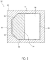
- excitation light can be guided from the light source to the detection target by using a single light guide unit, and the radiation light can be guided from the detection target to the photodetector, whereby the sensor can be miniaturized and the radiation light reception surface of the sensor can be enlarged at the same time.
- the light source 30 and the excitation light incident surface 51 are disposed so as to face each other via a visible light cut filter 71 which is a type of optical filter 70 and transmits ultraviolet light and cuts visible light.
- the photodetector 40 and the radiation light emission surface 52 are disposed so as to face each other via an ultraviolet light cut filter 72 and a color filter 73 which are one type of optical filter 70.
- the types of color filters 73 facing the photodetectors 40 can be changed to allow the photodetectors 40 to detect light of different wavelengths (colors).
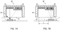
- the ultraviolet light contained in the excitation light emitted from the light source 30 passes through the visible light cut filter 71 and enters the light guide 50 from the excitation light incident surface 51.
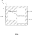
- the partition 21 prevents excitation light before entering the light guide 50 from reaching the photodetectors 40 directly or being reflected by the excitation light incident surface 51 or radiation light emission surface 52. In other words, the partition 21 functions as a light-blocking region.
- the excitation light that has reached the light incident/emission surface 53 is emitted from the light incident/emission surface 53.
- the light incident/emission surface 53 is disposed so as to face the detection target T.
- the detection target T is a security mark printed on a banknote or the like using an ink containing a material that emits radiation light such as fluorescence or phosphorescence when excited. Consequently, the detection target T is excited by the excitation light emitted from the light incident/emission surface 53, and emits radiation light such as fluorescence or phosphorescence.
- Radiation emitted from the detection target T enters the light guide 50 from the light incident/emission surface 53.
- the radiation light that has entered the light guide 50 is guided within the light guide 50 while being reflected by the side surface 55, and reaches the radiation light emission surface 52.
- the radiation light that has reached the radiation light emission surface 52 is emitted from the radiation light emission surface 52.
- radiation light of a predetermined color (wavelength) to be detected passes through the ultraviolet light cut filter 72 and the color filter 73 and is detected by the photodetectors 40.
- the excitation light is reflected on the surface of the detection target T, and the ultraviolet light contained in the reflected excitation light reaches the radiation light emission surface 52 and is emitted from the radiation light emission surface 52, but this ultraviolet light cannot pass through the ultraviolet light cut filter 72 and therefore does not reach the photodetectors 40.
- the optical sensor 10 uses the light guide 50 in the optical system. Therefore, unlike in the case of using a lens, it is not necessary to secure a gap corresponding to the focal distance of the lens in front of the photodetector 40.
- the single light guide 50 guides excitation light from the light source 30 to the detection target T and guides radiation light from the detection target T to the photodetector 40. Consequently, the optical sensor 10 has a compact configuration as a whole.
- the photodetector 40 having a large light receiving surface can be used. Therefore, the optical sensor 10 is suitable for installation in the apparatus and detection of radiation light from the moving detection target T.
- the light source 30 and the photodetector 40 are attached to the same board 60 and the board 60 serves as a lid of the holder 20, the cost of the components and the number of manufacturing steps can be reduced and the optical sensor 10 can therefore be manufactured at low cost.
- the photodetector 40 can be separated from the detection target T by at least the height of the light guide 50, the photodetector 40 can be prevented from being affected by the static electricity carried by the detection target T and/or the apparatus for conveying it. Moreover, since the light guide 50 occupies most of the space between the photodetector 40 and the detection target T, the radiation light emitted from the detection target T is also prevented from decaying before reaching the photodetector 40.
- each phosphorescence emitting material has a unique phosphorescence intensity decay time constant (a time required for the phosphorescence intensity to be 1/e).
- the phosphorescence intensity decay curve which is represented by a coordinate system having a horizontal axis representing the time elapsed after the turning-off of the light source 30 and a vertical axis representing the phosphorescence intensity, differs depending on each phosphorescence emitting material. Accordingly, after the turning-off of the light source 30, the phosphorescence emitting material contained in the detection target T can be determined by calculating the phosphorescence intensity many times and comparing each calculated phosphorescence intensity with the reference phosphorescence intensity.
- ⁇ is the decay time constant of the phosphorescence intensity.
- t 1 and t 2 are the times that have elapsed after the turning-off of the light source 30 until the first and second phosphorescence detections, respectively.
- P 1 and P 2 are the intensities of phosphorescence detected at the first and second times, respectively.
- the corrected phosphorescence intensity is compared with a reference value, so that the phosphorescence emitting material included in the detection target T can be determined more accurately.
- the authenticity of the detection target T or a sheet, a product, or the like provided with the detection target T can be determined.
- the phosphorescence emitting material contained in the detection target T can also be determined by calculating the decay time constant of the phosphorescence intensity based on the corrected phosphorescence intensity, and comparing the calculated decay time constant with a reference decay time constant.
- the conveyor apparatus control unit 91 controls the operation of the conveyor apparatus 80. Further, the conveyor apparatus control unit 91 calculates the travel distance of the belt, that is, the travel distance of the detection target T (information on the location of the detection target T) based on the number of pulses of the rotary encoder observed after the detection of the passage of the object X to be conveyed by the passage detection sensor.
- the operation of the light detection apparatus 100 is not limited to one that detects fluorescence or phosphorescence once as described above.
- fluorescence or phosphorescence may be detected more than once while the object X to be conveyed is passing.
- the authenticity of the object X to be conveyed can be determined by irradiating, with excitation light, a portion of the object X to be conveyed to which the detection target T should not be attached, and confirming that no radiation light is emitted.
- the reflective surface of the inner surface of the cylindrical holder 20 is, for example, a mirror surface.
- the mirror surface is formed by coating the inner surface of the holder 20 with a metal such as aluminum or silver or an alloy thereof, and finishing the surface of the metal by a known method.
- the reflective surface of the inner surface of the cylindrical holder 20 is not limited to the mirror surface formed by the above-described method, as long as most of the excitation light and the radiation light is reflected.
- the cylindrical holder 20 can work well even with, for example, a slit or a hole from which part of excitation light or reflective light leaks exists in a part of the cylindrical unit, as long as most of it is covered and the amount of leakage of excitation light or reflective light is small.
- the inner surface of the holder 20 also includes the side surface and the lower surface of the partition 21.
- P ⁇ is the intensity of phosphorescence emitted from a phosphorescent material ⁇
- a ⁇ is a constant determined by the concentration and the emission efficiency of the phosphorescent material ⁇
- t is the time elapsed from the time of the turning-off of excitation light to the time of detection
- ⁇ ⁇ is the decay time constant of the phosphorescence emitted from the phosphorescent material ⁇ .
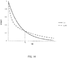
- the relationship between the phosphorescence intensity P ⁇ and the time t is a curve like L ⁇ shown in FIG. 14 .
- the curve L ⁇ is normalized with a maximum intensity of 1.
- A is a constant determined by the concentration and the emission efficiency of the phosphorescent material in the detection target T.
- the constant A can be calculated by substituting the phosphorescence intensity that was used to obtain the decay time constant ⁇ 1 and its detection time (for example, P 1 and t 1 ) into Expression 9.
- the detection unit 92 detects the intensity P 4 , intensity P 5 , intensity P 6 , and intensity P 7 of phosphorescence emitted from the detection target T when the time t 4 , time t 5 , time t 6 , and time t 7 have elapsed after the stop of emission of excitation light.
- the intensity of phosphorescence is detected four times to determine the phosphorescence in this example, the intensity of phosphorescence may be detected three times.
- the phosphorescence can be determined according to the method of this embodiment also by setting the first combination to a combination of intensities P 4 and P 5 and setting the second combination to a combination of intensities P 5 and P 6 or a combination of intensities P 4 and P 6 . It is optional to set the number of times of detection of phosphorescence intensity to five or more and select and use three or four of the detected phosphorescence intensities.
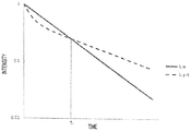
- the determination method of this example utilizes the fact that, when the graph of FIG. 14 is converted to the semi-logarithmic graph the vertical axis of which is the common logarithm shown in FIG. 15 , the curve L ⁇ is represented by a downward sloping line whereas the curve L ⁇ + ⁇ is represented by a downward sloping curve that intersects L ⁇ at the time t x .
- the detection unit 92 detects the intensity P 8 , intensity P 9 , and intensity P 10 of phosphorescence emitted from the detection target T when the time t 8 , time t 9 , and time t 10 have elapsed.
- the first combination which is a combination of two of these three intensities, is, for example, a combination of intensities P 8 and P 9 .
- the determination unit 94 calculates the first change rate (first change amount per unit time) R 1 of the logarithmic value of the phosphorescence intensity on the basis of the following Expression 12. [Expression 12]
- R 1 logP 9 ⁇ logP 8 / t 9 ⁇ t 8
- the determination unit 94 compares the first change rate R 1 with the second change rate R 2 . When the difference between them is less than or equal to a threshold, the determination unit 94 determines that the detected phosphorescence is emitted from a single phosphorescent material or a plurality of phosphorescent materials having the same decay time constant (this threshold may be 0).
- the second combination may be a combination of P 8 and P 10 .
- the phosphorescence intensity P 11 may be detected at time t 11
- the first combination may be a combination of P 8 and P 9
- the second combination may be a combination of P 10 and P 11 . It is also optional to make the number of detections of phosphorescence five or more and appropriately select and use three or four of the detected phosphorescence intensities.
- the authenticity of the detection target T (security feature) attached to an object X to be conveyed is determined, for example, in the following manner.
- the authenticity of the detection target T is determined in the following manner.
- the detection unit 92 detects red, green, and blue phosphorescence separately via three photodetectors 40.
- the determination unit 94 calculates the decay time constant of phosphorescence of each color.
- the determination unit 94 also determines whether or not the phosphorescence of each color has been emitted from multiple types of phosphorescent material having different decay time constants (whether it is "complex" or "single”).
- the determination unit 94 refers to information on Table 1 stored in the storage unit 95, and compares it with the decay time constant of phosphorescence determined for each color and the determination result.
- the detection target T is determined to be true. In contrast, when it does not match the attribute of the phosphorescence shown in Table 1, the detection target T is determined to be false.
- a feature of the detected fluorescence may be added to the feature of the detection target T.
- Table 1 whether or not fluorescence has been detected can be added as a feature for each of the red wavelength range, the green wavelength range, and the blue wavelength range.
- the second embodiment is summarized as follows.
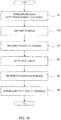
- the phosphorescence detection apparatus 100 calculates the decay time constant of phosphorescence for each photodetector 40 (for each color of radiation light) in Step S6 ( FIG. 10 ), and determines phosphorescence emitted from the phosphorescent material contained in the detection target T.
- the authenticity of the detection target T (security feature) attached to an object X to be conveyed is determined, for example, in the following manner.
- the authenticity of the detection target T is determined in the following manner.
- the detection unit 92 detects red, green, and blue phosphorescence separately via three photodetectors 40.
- the determination unit 94 calculates the decay time constant of phosphorescence of each color.
- the determination unit 94 refers to information on Table 2 stored in the storage unit 95, and compares it with the decay time constant of phosphorescence determined for each color. When the result shows that the attributes of the phosphorescence that have been emitted from a certain detection target T match the attributes shown in Table 2, the detection target T is determined to be true. In contrast, when it does not match the attributes of the phosphorescence shown in Table 2, the detection target T is determined to be false.
- the authenticity of the detection target T and consequently the authenticity of an object X to be conveyed, such as a sheet, can be determined using a feature that is the presence or absence of phosphorescence and the decay time constant.
- the phosphorescence to be recognized should be phosphorescence that decays in a certain short time.
- the phosphorescence decay is too fast, the phosphorescence decays in a very short time, making it difficult to accurately detect the phosphorescence intensity.
- phosphorescence to be recognized is preferably phosphorescence having a decay time constant of 0.2 msec or more and 10 msec or less.
- the decay time constants of phosphorescence to be recognized that is, the decay curves of phosphorescence
- three types of phosphorescent material that emit phosphorescence having decay time constants of 0.2 msec, 1 msec, and 10 msec, respectively may be used as phosphorescent materials for the detection target T.
- FIG. 18 shows the decay curves of the phosphorescence intensity ratio obtained with decay time constants of 0.2 msec, 0.4 msec, 0.9 msec, 2 msec, and 10 msec, respectively.
- the vertical axis represents the ratio of phosphorescence intensity to the maximum intensity (that is, the phosphorescence intensity detected in the first detection)
- the horizontal axis represents the time elapsed from the first detection of phosphorescence intensity.
- the detection target T for example, five types of phosphorescent material that emit phosphorescence having decay time constants of 0.2 msec, 0.4 msec, 0.9 msec, 2 msec, and 10 msec, respectively may be used as phosphorescent materials for the detection target T.
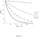
- the subsequent detection of a phosphorescence intensity is performed 0.20 msec or more after the first detection of a phosphorescence intensity, whether the time constant of the detected phosphorescence is 1 msec or 10 msec can be recognized with reliability.
- the subsequent detection is preferably performed within 1 msec after the first detection.
- Table 4 shows the values on the four decay curves shown in FIG. 17 .
- the difference between the phosphorescence intensity ratio with a decay time constant of 1 msec and the phosphorescence intensity ratio with a decay time constant of 10 msec is also greater than 0.2. Therefore, when the subsequent detection of a phosphorescence intensity is performed a certain time, which is in the range of 0.30 msec to 0.45 msec, after the first detection of a phosphorescence intensity, whether the time constant of the detected phosphorescence is either 0.2 msec, 0.4 msec, 1 msec, or 10 msec can be recognized with more reliability.
- the additional detection of a phosphorescence intensity is performed not only when the subsequent detection is performed at the time when the difference between intensity ratios becomes 0.2 or more, or when there are five types of phosphorescent material to be recognized. For example, when there are four types of phosphorescent material to be recognized and the subsequent detection is performed at the time when the difference between the intensity ratios becomes 0.15 or more, additional detection of a phosphorescence intensity may be performed.
- the additional detection is not only performed after the subsequent detection. In other words, the additional detection may be performed after the first detection and before the subsequent detection. In other words, either the second timing or the third timing may be earlier.
- the range of the intensity ratio at the second timing (and, when necessary, the third timing) is determined in advance and stored in the storage unit 95.
- the first detection of a phosphorescence intensity is performed for each photodetector 40, that is, for each phosphorescent color.
- the subsequent detection of the phosphorescence intensity is performed at the second timing for each photodetector 40, that is, for each phosphorescent color, and the intensity ratio at the second timing is calculated for each phosphorescent color. Subsequently, whether or not the intensity ratio at the second timing is within a predetermined range is determined for each phosphorescent color.
- the phosphorescence detection apparatus and the phosphorescence detection method of the present invention which detect a phosphorescent material attached as a security feature on the surface of a sheet, represented by value documents such as banknotes or securities, irradiate a phosphorescent material to be a detection target with excitation light to detect the phosphorescence emitted from the phosphorescent material. Since features, such as the spectrum and decay characteristics of phosphorescence, are determined by the composition of the phosphorescent material, the authenticity of the security feature can be determined by detecting phosphorescence and comparing their features.
Landscapes
- Health & Medical Sciences (AREA)
- General Physics & Mathematics (AREA)
- Physics & Mathematics (AREA)
- General Health & Medical Sciences (AREA)
- Nuclear Medicine, Radiotherapy & Molecular Imaging (AREA)
- Toxicology (AREA)
- Spectroscopy & Molecular Physics (AREA)
- Life Sciences & Earth Sciences (AREA)
- Chemical & Material Sciences (AREA)
- Analytical Chemistry (AREA)
- Biochemistry (AREA)
- Immunology (AREA)
- Pathology (AREA)
- Investigating, Analyzing Materials By Fluorescence Or Luminescence (AREA)
- Inspection Of Paper Currency And Valuable Securities (AREA)
Applications Claiming Priority (4)
| Application Number | Priority Date | Filing Date | Title |
|---|---|---|---|
| JP2017061074A JP6944258B2 (ja) | 2017-03-27 | 2017-03-27 | 燐光検出装置、紙葉類処理装置及び燐光検出方法 |
| JP2017061081A JP6944259B2 (ja) | 2017-03-27 | 2017-03-27 | 燐光検出装置、紙葉類処理装置及び燐光検出方法 |
| JP2017061065A JP7017862B2 (ja) | 2017-03-27 | 2017-03-27 | 光センサ、光検出装置、紙葉類処理装置及び光検出方法 |
| PCT/JP2018/012046 WO2018181134A1 (ja) | 2017-03-27 | 2018-03-26 | 光センサ、光検出装置、紙葉類処理装置、光検出方法及び燐光検出装置 |
Publications (3)
| Publication Number | Publication Date |
|---|---|
| EP3605067A1 true EP3605067A1 (de) | 2020-02-05 |
| EP3605067A4 EP3605067A4 (de) | 2021-03-31 |
| EP3605067B1 EP3605067B1 (de) | 2024-10-02 |
Family
ID=63676020
Family Applications (1)
| Application Number | Title | Priority Date | Filing Date |
|---|---|---|---|
| EP18775854.5A Active EP3605067B1 (de) | 2017-03-27 | 2018-03-26 | Optischer sensor, lichtdetektor, papierbogenverarbeitungsvorrichtung, lichtdetektionsverfahren und phosphoreszenzdetektor |
Country Status (5)
| Country | Link |
|---|---|
| US (1) | US11467087B2 (de) |
| EP (1) | EP3605067B1 (de) |
| CN (1) | CN110537092A (de) |
| AU (1) | AU2018242894B2 (de) |
| WO (1) | WO2018181134A1 (de) |
Cited By (3)
| Publication number | Priority date | Publication date | Assignee | Title |
|---|---|---|---|---|
| WO2021105895A1 (en) * | 2019-11-25 | 2021-06-03 | Spin & Turn - Consultadoria De Software, Lda | Device and method for detecting reactive luminescent nano- or micro- particles |
| WO2021228433A1 (de) * | 2020-05-14 | 2021-11-18 | Giesecke+Devrient Currency Technology Gmbh | Verfahren zum klassifizieren einer banknote, klassifizierungsvorrichtung, verfahren zum erzeugen eines klassifikators und verwendung zur klassifizierung einer banknote |
| US12578257B2 (en) | 2023-03-07 | 2026-03-17 | Spin & Turn—Consultadoria de Software, Lda | Device and method for detecting reactive luminescent particles in carbon-based nanomaterials |
Families Citing this family (5)
| Publication number | Priority date | Publication date | Assignee | Title |
|---|---|---|---|---|
| CN114868164A (zh) * | 2020-02-26 | 2022-08-05 | 深圳帧观德芯科技有限公司 | 纸币计数机 |
| EP4295333B1 (de) | 2021-02-16 | 2024-11-06 | Giesecke+Devrient Currency Technology GmbH | Sensor zur prüfung der lumineszenz von wertdokumenten |
| DE102021000807A1 (de) | 2021-02-16 | 2022-08-18 | Giesecke+Devrient Currency Technology Gmbh | Sensor zur Prüfung von Wertdokumenten |
| JP2024007792A (ja) * | 2022-07-06 | 2024-01-19 | グローリー株式会社 | 紙葉類識別装置及び紙葉類処理装置 |
| EP4598434A2 (de) * | 2022-10-06 | 2025-08-13 | Worcester Polytechnic Institute | Exponentielle signalmessvorrichtung |
Family Cites Families (41)
| Publication number | Priority date | Publication date | Assignee | Title |
|---|---|---|---|---|
| US4977325A (en) * | 1989-07-12 | 1990-12-11 | P B Diagnostic Systems, Inc. | Optical read system and immunoassay method |
| DE4022020A1 (de) * | 1990-07-11 | 1992-01-16 | Gao Ges Automation Org | Vorrichtung und verfahren zur pruefung von dokumenten |
| EP0622762B1 (de) | 1993-04-27 | 1998-07-01 | The Furukawa Electric Co., Ltd. | Vorrichtung zum Nachweis von Fluoreszenz |
| JP3228372B2 (ja) * | 1993-04-27 | 2001-11-12 | 古河電気工業株式会社 | 蛍光検出装置 |
| US5918960A (en) * | 1994-01-04 | 1999-07-06 | Mars Incorporated | Detection of counterfeit objects, for instance counterfeit banknotes |
| DE19651101A1 (de) | 1996-12-09 | 1998-06-10 | Giesecke & Devrient Gmbh | Vorrichtung und Verfahren zur Detektion von fluoreszentem und phosphoreszentem Licht |
| DE19837050A1 (de) * | 1998-08-17 | 2000-02-24 | Gardena Kress & Kastner Gmbh | Flüssigkeitsmeldeeinrichtung |
| JP4689825B2 (ja) * | 1998-08-26 | 2011-05-25 | センサーズ・フォー・メデセン・アンド・サイエンス・インコーポレーテッド | 光学式検知装置 |
| DE19958048A1 (de) | 1999-12-03 | 2001-06-07 | Giesecke & Devrient Gmbh | Vorrichtung und Verfahren zur Echtheitsprüfung von Banknoten |
| JP2001291458A (ja) * | 2000-02-01 | 2001-10-19 | Stanley Electric Co Ltd | 光学式タッチスイッチ装置 |
| DK1158459T3 (da) | 2000-05-16 | 2009-02-23 | Sicpa Holding Sa | Fremgangsmåde, indretning og sikkerhedssystem, alle til at berigtige en markering |
| US20020020808A1 (en) | 2000-06-29 | 2002-02-21 | Takumi Kado | Optical touch switcing device |
| JP2002197506A (ja) * | 2000-12-26 | 2002-07-12 | Glory Ltd | Uv・蛍光検出装置及びそのセンシング方法 |
| US6690452B2 (en) | 2001-04-18 | 2004-02-10 | Paul A. Wilks, Jr. | Monitor having a polymer internal reflective element |
| DE10127837A1 (de) | 2001-06-08 | 2003-01-23 | Giesecke & Devrient Gmbh | Vorrichtung und Verfahren zur Untersuchung von Dokumenten |
| JP4596690B2 (ja) * | 2001-06-25 | 2010-12-08 | 日本電産コパル株式会社 | 紙葉類蛍光検出センサ |
| AU2002360271A1 (en) | 2001-10-11 | 2003-04-22 | Sentelligence, Inc. | Low-cost on-line and in-line spectral sensors based on solid-state source and detector combinations |
| TWI293363B (en) | 2001-12-11 | 2008-02-11 | Sensors For Med & Science Inc | High performance fluorescent optical sensor |
| CA2453229A1 (en) * | 2003-12-12 | 2005-06-12 | Cashcode Company Inc. | Reflective optical sensor for bill validator |
| CN1898704B (zh) * | 2004-02-12 | 2010-04-21 | 日本电产科宝株式会社 | 检查装置 |
| US7911655B2 (en) * | 2004-10-06 | 2011-03-22 | Iuval Hatzav | System for extracting information from an identity card |
| US7317533B2 (en) | 2005-01-14 | 2008-01-08 | Jetalon Solutions, Inc. | Metal ion concentration analysis for liquids |
| US20060241351A1 (en) | 2005-04-08 | 2006-10-26 | Rosemount Analytical Inc. | Integrated optical device for luminescence sensing |
| US7262420B1 (en) | 2006-03-03 | 2007-08-28 | Ncr Corporation | Secure tag validation |
| JP2008197088A (ja) | 2007-01-19 | 2008-08-28 | Shimadzu Corp | 蛍光検出器 |
| CN102494776B (zh) * | 2007-04-03 | 2014-11-19 | 武藤工业株式会社 | 分光光度计和方法 |
| US8328102B2 (en) * | 2009-12-21 | 2012-12-11 | Honeywell International Inc. | Method and authentication apparatus for authenticating value documents |
| CN102176260A (zh) | 2010-12-30 | 2011-09-07 | 南京理工速必得科技股份有限公司 | 一种检测纸币荧光油墨的方法及其实现装置 |
| PH12013502493A1 (en) | 2011-06-06 | 2017-05-31 | Sicpa Holding Sa | In-line decay-time scanner |
| US20130015651A1 (en) | 2011-07-15 | 2013-01-17 | Honeywell International Inc. | Luminescent phosphor compounds, articles including such compounds, and methods for their production and use |
| US8759794B2 (en) | 2012-07-20 | 2014-06-24 | Honeywell International Inc. | Articles, methods of validating the same, and validation systems employing decay constant modulation |
| DE102012025263A1 (de) | 2012-12-21 | 2014-06-26 | Giesecke & Devrient Gmbh | Sensor und Verfahren zur Prüfung von Wertdokumenten |
| US10176659B2 (en) | 2013-09-30 | 2019-01-08 | Glory Ltd. | Paper sheet authentication apparatus |
| EP3133562B1 (de) | 2014-04-18 | 2023-02-15 | Glory Ltd. | Papierbogenauthentizitätsbestimmungsvorrichtung und papierbogenauthentizitätsbestimmungsverfahren |
| JP6288709B2 (ja) | 2014-05-22 | 2018-03-07 | グローリー株式会社 | 蛍光・燐光検知装置 |
| US9761077B2 (en) * | 2014-07-02 | 2017-09-12 | Toshiba International Corporation | Bank note processing system having a combined florescence and phosphorescence detection system |
| US10650630B2 (en) * | 2014-10-31 | 2020-05-12 | Honeywell International Inc. | Authentication systems, authentication devices, and methods for authenticating a value article |
| JP2017061074A (ja) | 2015-09-24 | 2017-03-30 | 株式会社Screenホールディングス | オフセット印刷装置及び、オフセット印刷方法 |
| JP5957131B1 (ja) | 2015-09-24 | 2016-07-27 | 株式会社浅野研究所 | 熱成形装置および熱成形方法 |
| JP6480295B2 (ja) | 2015-09-25 | 2019-03-06 | 藤森工業株式会社 | 剥離性に優れた離型フィルム |
| JP6867270B2 (ja) * | 2017-10-19 | 2021-04-28 | グローリー株式会社 | 光ラインセンサユニット |
-
2018
- 2018-03-26 EP EP18775854.5A patent/EP3605067B1/de active Active
- 2018-03-26 US US16/498,440 patent/US11467087B2/en active Active
- 2018-03-26 CN CN201880020836.4A patent/CN110537092A/zh active Pending
- 2018-03-26 WO PCT/JP2018/012046 patent/WO2018181134A1/ja not_active Ceased
- 2018-03-26 AU AU2018242894A patent/AU2018242894B2/en active Active
Cited By (5)
| Publication number | Priority date | Publication date | Assignee | Title |
|---|---|---|---|---|
| WO2021105895A1 (en) * | 2019-11-25 | 2021-06-03 | Spin & Turn - Consultadoria De Software, Lda | Device and method for detecting reactive luminescent nano- or micro- particles |
| US12050167B2 (en) | 2019-11-25 | 2024-07-30 | Spin & Turn—Consultadoria de Software, Lda | Device and method for detecting reactive luminescent nano- or micro- particles |
| WO2021228433A1 (de) * | 2020-05-14 | 2021-11-18 | Giesecke+Devrient Currency Technology Gmbh | Verfahren zum klassifizieren einer banknote, klassifizierungsvorrichtung, verfahren zum erzeugen eines klassifikators und verwendung zur klassifizierung einer banknote |
| US12322237B2 (en) | 2020-05-14 | 2025-06-03 | Giesecke+Devrient Currency Technology Gmbh | Method for classifying a banknote, classification device, method for producing a classifier and use for the classification of a banknote |
| US12578257B2 (en) | 2023-03-07 | 2026-03-17 | Spin & Turn—Consultadoria de Software, Lda | Device and method for detecting reactive luminescent particles in carbon-based nanomaterials |
Also Published As
| Publication number | Publication date |
|---|---|
| CN110537092A (zh) | 2019-12-03 |
| WO2018181134A1 (ja) | 2018-10-04 |
| AU2018242894A1 (en) | 2019-10-17 |
| EP3605067A4 (de) | 2021-03-31 |
| AU2018242894B2 (en) | 2020-11-05 |
| EP3605067B1 (de) | 2024-10-02 |
| US20210116370A1 (en) | 2021-04-22 |
| US11467087B2 (en) | 2022-10-11 |
Similar Documents
| Publication | Publication Date | Title |
|---|---|---|
| EP3605067B1 (de) | Optischer sensor, lichtdetektor, papierbogenverarbeitungsvorrichtung, lichtdetektionsverfahren und phosphoreszenzdetektor | |
| US10176659B2 (en) | Paper sheet authentication apparatus | |
| EP2290622B1 (de) | Lichterkennungsvorrichtung und Blattverarbeitungsvorrichtung damit | |
| EP2718910B1 (de) | Inline-zerfallszeitscanner | |
| US6529269B1 (en) | Paper sheet identification method and device | |
| EP1254435B1 (de) | Gerät und verfahren zum überprüfen eines dokumentes | |
| US9989411B2 (en) | Sensor and method for checking authenticity of valuable documents with a luminscent security feature | |
| JP2003006625A (ja) | 紙葉類蛍光検出センサ | |
| US11756362B2 (en) | Method and sensor for testing documents | |
| US20200273279A1 (en) | Completeness check of a value document | |
| JP7017862B2 (ja) | 光センサ、光検出装置、紙葉類処理装置及び光検出方法 | |
| EP3780570B1 (de) | Lichtdetektionssensor, lichtdetektionsvorrichtung und papierbogenverarbeitungsvorrichtung | |
| RU2530276C2 (ru) | Устройство аутентификации, способ аутентификации и датчик флуоресценции | |
| JP6944259B2 (ja) | 燐光検出装置、紙葉類処理装置及び燐光検出方法 | |
| US20040056084A1 (en) | Document handling apparatus | |
| JP2005078280A (ja) | 紙幣識別装置 | |
| JP6944258B2 (ja) | 燐光検出装置、紙葉類処理装置及び燐光検出方法 | |
| RU177966U1 (ru) | Устройство для обработки банкнот с возможностью проверки защитных антистоксовых меток | |
| RU158936U1 (ru) | Устройство для автоматической проверки наличия на банкнотах защитных антистоксовых меток (спецэлемент и) | |
| WO2010134092A2 (en) | Overlapped note detector | |
| HK1178301B (en) | Sensor for verifying value documents |
Legal Events
| Date | Code | Title | Description |
|---|---|---|---|
| STAA | Information on the status of an ep patent application or granted ep patent |
Free format text: STATUS: THE INTERNATIONAL PUBLICATION HAS BEEN MADE |
|
| PUAI | Public reference made under article 153(3) epc to a published international application that has entered the european phase |
Free format text: ORIGINAL CODE: 0009012 |
|
| STAA | Information on the status of an ep patent application or granted ep patent |
Free format text: STATUS: REQUEST FOR EXAMINATION WAS MADE |
|
| 17P | Request for examination filed |
Effective date: 20190927 |
|
| AK | Designated contracting states |
Kind code of ref document: A1 Designated state(s): AL AT BE BG CH CY CZ DE DK EE ES FI FR GB GR HR HU IE IS IT LI LT LU LV MC MK MT NL NO PL PT RO RS SE SI SK SM TR |
|
| RIC1 | Information provided on ipc code assigned before grant |
Ipc: G01J 1/02 20060101ALI20201118BHEP Ipc: G01N 21/64 20060101AFI20201118BHEP Ipc: G07D 7/121 20160101ALI20201118BHEP Ipc: G01J 1/42 20060101ALI20201118BHEP Ipc: H01L 31/12 20060101ALI20201118BHEP |
|
| A4 | Supplementary search report drawn up and despatched |
Effective date: 20210225 |
|
| RIC1 | Information provided on ipc code assigned before grant |
Ipc: H01L 31/12 20060101ALI20210219BHEP Ipc: G01J 1/02 20060101ALI20210219BHEP Ipc: G01N 21/64 20060101AFI20210219BHEP Ipc: G07D 7/121 20160101ALI20210219BHEP Ipc: G01J 1/42 20060101ALI20210219BHEP |
|
| STAA | Information on the status of an ep patent application or granted ep patent |
Free format text: STATUS: EXAMINATION IS IN PROGRESS |
|
| 17Q | First examination report despatched |
Effective date: 20220825 |
|
| P01 | Opt-out of the competence of the unified patent court (upc) registered |
Effective date: 20230531 |
|
| GRAP | Despatch of communication of intention to grant a patent |
Free format text: ORIGINAL CODE: EPIDOSNIGR1 |
|
| STAA | Information on the status of an ep patent application or granted ep patent |
Free format text: STATUS: GRANT OF PATENT IS INTENDED |
|
| RIC1 | Information provided on ipc code assigned before grant |
Ipc: H01L 31/12 20060101ALI20240126BHEP Ipc: G07D 7/121 20160101ALI20240126BHEP Ipc: G01J 1/42 20060101ALI20240126BHEP Ipc: G01J 1/02 20060101ALI20240126BHEP Ipc: G01N 21/86 20060101ALI20240126BHEP Ipc: G01N 21/64 20060101AFI20240126BHEP |
|
| INTG | Intention to grant announced |
Effective date: 20240214 |
|
| GRAJ | Information related to disapproval of communication of intention to grant by the applicant or resumption of examination proceedings by the epo deleted |
Free format text: ORIGINAL CODE: EPIDOSDIGR1 |
|
| STAA | Information on the status of an ep patent application or granted ep patent |
Free format text: STATUS: EXAMINATION IS IN PROGRESS |
|
| GRAP | Despatch of communication of intention to grant a patent |
Free format text: ORIGINAL CODE: EPIDOSNIGR1 |
|
| INTC | Intention to grant announced (deleted) | ||
| STAA | Information on the status of an ep patent application or granted ep patent |
Free format text: STATUS: GRANT OF PATENT IS INTENDED |
|
| INTG | Intention to grant announced |
Effective date: 20240502 |
|
| GRAS | Grant fee paid |
Free format text: ORIGINAL CODE: EPIDOSNIGR3 |
|
| GRAA | (expected) grant |
Free format text: ORIGINAL CODE: 0009210 |
|
| STAA | Information on the status of an ep patent application or granted ep patent |
Free format text: STATUS: THE PATENT HAS BEEN GRANTED |
|
| AK | Designated contracting states |
Kind code of ref document: B1 Designated state(s): AL AT BE BG CH CY CZ DE DK EE ES FI FR GB GR HR HU IE IS IT LI LT LU LV MC MK MT NL NO PL PT RO RS SE SI SK SM TR |
|
| REG | Reference to a national code |
Ref country code: GB Ref legal event code: FG4D |
|
| REG | Reference to a national code |
Ref country code: CH Ref legal event code: EP |
|
| REG | Reference to a national code |
Ref country code: IE Ref legal event code: FG4D |
|
| REG | Reference to a national code |
Ref country code: DE Ref legal event code: R096 Ref document number: 602018074968 Country of ref document: DE |
|
| REG | Reference to a national code |
Ref country code: NL Ref legal event code: FP |
|
| REG | Reference to a national code |
Ref country code: LT Ref legal event code: MG9D |
|
| REG | Reference to a national code |
Ref country code: AT Ref legal event code: MK05 Ref document number: 1728825 Country of ref document: AT Kind code of ref document: T Effective date: 20241002 |
|
| PG25 | Lapsed in a contracting state [announced via postgrant information from national office to epo] |
Ref country code: HR Free format text: LAPSE BECAUSE OF FAILURE TO SUBMIT A TRANSLATION OF THE DESCRIPTION OR TO PAY THE FEE WITHIN THE PRESCRIBED TIME-LIMIT Effective date: 20241002 Ref country code: PT Free format text: LAPSE BECAUSE OF FAILURE TO SUBMIT A TRANSLATION OF THE DESCRIPTION OR TO PAY THE FEE WITHIN THE PRESCRIBED TIME-LIMIT Effective date: 20250203 Ref country code: IS Free format text: LAPSE BECAUSE OF FAILURE TO SUBMIT A TRANSLATION OF THE DESCRIPTION OR TO PAY THE FEE WITHIN THE PRESCRIBED TIME-LIMIT Effective date: 20250202 |
|
| PG25 | Lapsed in a contracting state [announced via postgrant information from national office to epo] |
Ref country code: FI Free format text: LAPSE BECAUSE OF FAILURE TO SUBMIT A TRANSLATION OF THE DESCRIPTION OR TO PAY THE FEE WITHIN THE PRESCRIBED TIME-LIMIT Effective date: 20241002 |
|
| PG25 | Lapsed in a contracting state [announced via postgrant information from national office to epo] |
Ref country code: BG Free format text: LAPSE BECAUSE OF FAILURE TO SUBMIT A TRANSLATION OF THE DESCRIPTION OR TO PAY THE FEE WITHIN THE PRESCRIBED TIME-LIMIT Effective date: 20241002 |
|
| PG25 | Lapsed in a contracting state [announced via postgrant information from national office to epo] |
Ref country code: ES Free format text: LAPSE BECAUSE OF FAILURE TO SUBMIT A TRANSLATION OF THE DESCRIPTION OR TO PAY THE FEE WITHIN THE PRESCRIBED TIME-LIMIT Effective date: 20241002 |
|
| PG25 | Lapsed in a contracting state [announced via postgrant information from national office to epo] |
Ref country code: NO Free format text: LAPSE BECAUSE OF FAILURE TO SUBMIT A TRANSLATION OF THE DESCRIPTION OR TO PAY THE FEE WITHIN THE PRESCRIBED TIME-LIMIT Effective date: 20250102 |
|
| PG25 | Lapsed in a contracting state [announced via postgrant information from national office to epo] |
Ref country code: LV Free format text: LAPSE BECAUSE OF FAILURE TO SUBMIT A TRANSLATION OF THE DESCRIPTION OR TO PAY THE FEE WITHIN THE PRESCRIBED TIME-LIMIT Effective date: 20241002 Ref country code: AT Free format text: LAPSE BECAUSE OF FAILURE TO SUBMIT A TRANSLATION OF THE DESCRIPTION OR TO PAY THE FEE WITHIN THE PRESCRIBED TIME-LIMIT Effective date: 20241002 Ref country code: GR Free format text: LAPSE BECAUSE OF FAILURE TO SUBMIT A TRANSLATION OF THE DESCRIPTION OR TO PAY THE FEE WITHIN THE PRESCRIBED TIME-LIMIT Effective date: 20250103 |
|
| PG25 | Lapsed in a contracting state [announced via postgrant information from national office to epo] |
Ref country code: PL Free format text: LAPSE BECAUSE OF FAILURE TO SUBMIT A TRANSLATION OF THE DESCRIPTION OR TO PAY THE FEE WITHIN THE PRESCRIBED TIME-LIMIT Effective date: 20241002 Ref country code: CZ Free format text: LAPSE BECAUSE OF FAILURE TO SUBMIT A TRANSLATION OF THE DESCRIPTION OR TO PAY THE FEE WITHIN THE PRESCRIBED TIME-LIMIT Effective date: 20241002 |
|
| PG25 | Lapsed in a contracting state [announced via postgrant information from national office to epo] |
Ref country code: RS Free format text: LAPSE BECAUSE OF FAILURE TO SUBMIT A TRANSLATION OF THE DESCRIPTION OR TO PAY THE FEE WITHIN THE PRESCRIBED TIME-LIMIT Effective date: 20250102 |
|
| PG25 | Lapsed in a contracting state [announced via postgrant information from national office to epo] |
Ref country code: SM Free format text: LAPSE BECAUSE OF FAILURE TO SUBMIT A TRANSLATION OF THE DESCRIPTION OR TO PAY THE FEE WITHIN THE PRESCRIBED TIME-LIMIT Effective date: 20241002 |
|
| REG | Reference to a national code |
Ref country code: DE Ref legal event code: R097 Ref document number: 602018074968 Country of ref document: DE |
|
| PG25 | Lapsed in a contracting state [announced via postgrant information from national office to epo] |
Ref country code: DK Free format text: LAPSE BECAUSE OF FAILURE TO SUBMIT A TRANSLATION OF THE DESCRIPTION OR TO PAY THE FEE WITHIN THE PRESCRIBED TIME-LIMIT Effective date: 20241002 |
|
| PG25 | Lapsed in a contracting state [announced via postgrant information from national office to epo] |
Ref country code: EE Free format text: LAPSE BECAUSE OF FAILURE TO SUBMIT A TRANSLATION OF THE DESCRIPTION OR TO PAY THE FEE WITHIN THE PRESCRIBED TIME-LIMIT Effective date: 20241002 |
|
| PG25 | Lapsed in a contracting state [announced via postgrant information from national office to epo] |
Ref country code: RO Free format text: LAPSE BECAUSE OF FAILURE TO SUBMIT A TRANSLATION OF THE DESCRIPTION OR TO PAY THE FEE WITHIN THE PRESCRIBED TIME-LIMIT Effective date: 20241002 |
|
| PG25 | Lapsed in a contracting state [announced via postgrant information from national office to epo] |
Ref country code: SK Free format text: LAPSE BECAUSE OF FAILURE TO SUBMIT A TRANSLATION OF THE DESCRIPTION OR TO PAY THE FEE WITHIN THE PRESCRIBED TIME-LIMIT Effective date: 20241002 |
|
| PG25 | Lapsed in a contracting state [announced via postgrant information from national office to epo] |
Ref country code: IT Free format text: LAPSE BECAUSE OF FAILURE TO SUBMIT A TRANSLATION OF THE DESCRIPTION OR TO PAY THE FEE WITHIN THE PRESCRIBED TIME-LIMIT Effective date: 20241002 |
|
| PLBE | No opposition filed within time limit |
Free format text: ORIGINAL CODE: 0009261 |
|
| STAA | Information on the status of an ep patent application or granted ep patent |
Free format text: STATUS: NO OPPOSITION FILED WITHIN TIME LIMIT |
|
| PG25 | Lapsed in a contracting state [announced via postgrant information from national office to epo] |
Ref country code: SE Free format text: LAPSE BECAUSE OF FAILURE TO SUBMIT A TRANSLATION OF THE DESCRIPTION OR TO PAY THE FEE WITHIN THE PRESCRIBED TIME-LIMIT Effective date: 20241002 |
|
| 26N | No opposition filed |
Effective date: 20250703 |
|
| PG25 | Lapsed in a contracting state [announced via postgrant information from national office to epo] |
Ref country code: MC Free format text: LAPSE BECAUSE OF FAILURE TO SUBMIT A TRANSLATION OF THE DESCRIPTION OR TO PAY THE FEE WITHIN THE PRESCRIBED TIME-LIMIT Effective date: 20241002 |
|
| REG | Reference to a national code |
Ref country code: CH Ref legal event code: H13 Free format text: ST27 STATUS EVENT CODE: U-0-0-H10-H13 (AS PROVIDED BY THE NATIONAL OFFICE) Effective date: 20251024 |
|
| PG25 | Lapsed in a contracting state [announced via postgrant information from national office to epo] |
Ref country code: LU Free format text: LAPSE BECAUSE OF NON-PAYMENT OF DUE FEES Effective date: 20250326 |
|
| GBPC | Gb: european patent ceased through non-payment of renewal fee |
Effective date: 20250326 |
|
| REG | Reference to a national code |
Ref country code: BE Ref legal event code: MM Effective date: 20250331 |
|
| PG25 | Lapsed in a contracting state [announced via postgrant information from national office to epo] |
Ref country code: GB Free format text: LAPSE BECAUSE OF NON-PAYMENT OF DUE FEES Effective date: 20250326 |
|
| PG25 | Lapsed in a contracting state [announced via postgrant information from national office to epo] |
Ref country code: BE Free format text: LAPSE BECAUSE OF NON-PAYMENT OF DUE FEES Effective date: 20250331 |
|
| PG25 | Lapsed in a contracting state [announced via postgrant information from national office to epo] |
Ref country code: CH Free format text: LAPSE BECAUSE OF NON-PAYMENT OF DUE FEES Effective date: 20250331 |
|
| PG25 | Lapsed in a contracting state [announced via postgrant information from national office to epo] |
Ref country code: IE Free format text: LAPSE BECAUSE OF NON-PAYMENT OF DUE FEES Effective date: 20250326 |
|
| PGFP | Annual fee paid to national office [announced via postgrant information from national office to epo] |
Ref country code: DE Payment date: 20260319 Year of fee payment: 9 |
|
| PGFP | Annual fee paid to national office [announced via postgrant information from national office to epo] |
Ref country code: NL Payment date: 20260319 Year of fee payment: 9 |
|
| PGFP | Annual fee paid to national office [announced via postgrant information from national office to epo] |
Ref country code: FR Payment date: 20260320 Year of fee payment: 9 |