EP3604966B1 - Gehäuse und wandmontierte klimaanlage - Google Patents
Gehäuse und wandmontierte klimaanlage Download PDFInfo
- Publication number
- EP3604966B1 EP3604966B1 EP18903064.6A EP18903064A EP3604966B1 EP 3604966 B1 EP3604966 B1 EP 3604966B1 EP 18903064 A EP18903064 A EP 18903064A EP 3604966 B1 EP3604966 B1 EP 3604966B1
- Authority
- EP
- European Patent Office
- Prior art keywords
- housing
- panel
- decorative strip
- strips
- strip
- Prior art date
- Legal status (The legal status is an assumption and is not a legal conclusion. Google has not performed a legal analysis and makes no representation as to the accuracy of the status listed.)
- Active
Links
Images


Classifications
-
- F—MECHANICAL ENGINEERING; LIGHTING; HEATING; WEAPONS; BLASTING
- F24—HEATING; RANGES; VENTILATING
- F24F—AIR-CONDITIONING; AIR-HUMIDIFICATION; VENTILATION; USE OF AIR CURRENTS FOR SCREENING
- F24F13/00—Details common to, or for air-conditioning, air-humidification, ventilation or use of air currents for screening
- F24F13/20—Casings or covers
-
- F—MECHANICAL ENGINEERING; LIGHTING; HEATING; WEAPONS; BLASTING
- F24—HEATING; RANGES; VENTILATING
- F24F—AIR-CONDITIONING; AIR-HUMIDIFICATION; VENTILATION; USE OF AIR CURRENTS FOR SCREENING
- F24F1/00—Room units for air-conditioning, e.g. separate or self-contained units or units receiving primary air from a central station
- F24F1/0007—Indoor units, e.g. fan coil units
- F24F1/0043—Indoor units, e.g. fan coil units characterised by mounting arrangements
- F24F1/0057—Indoor units, e.g. fan coil units characterised by mounting arrangements mounted in or on a wall
Definitions
- the present disclosure generally relates to the technical field of air conditioner, and more particularly relates to a housing, and an indoor unit of a wall-mounted air conditioner.
- the demand for appearance of the indoor unit of the wall-mounted air conditioner is increasing with continuous improvement of human daily life. So the housings of most indoor units are now arranged with decorative strips for beautifying appearance. However, the decorative effect is poor as the decorative strip is only arranged on the panel. In consequence, user's demand for good appearance has not been satisfied.
- CN 103 868 218 A discloses an indoor unit of an air conditioner including a housing body, a front panel, and a decorative panel.
- the housing body includes a front housing and a rear housing.
- a front panel and a decorative panel for decorative purposes are respectively wrapped around the front and side portions of the front case.
- the decorative panel includes a decorative panel bottom located below the front casing and a side portion extending upward from both ends of the decorative panel bottom and enclosing the side of the front casing.
- the decorative panel with its portions and the housing body are fixedly connected by a snap connection structure. Further state of the art is known from CN 203 024 372 U .
- the present invention provides a a housing according to claim 1.
- a thickness of a connecting portion of each of the two side decorative strips is same as that of a connecting portion of the front decorative strip along a front-back direction.
- a thickness of other portion of each of the two side decorative strips is gradually decreased along a direction away from the connecting portion.
- the front decorative strip is fastened and fixed to the panel.
- the front decorative strip includes an upper surface and a positioning element protruded upwards from the upper surface.
- the panel includes a lower edge and an avoiding hole formed in the lower edge, and the positioning element is locked in the avoiding hole.
- the housing further includes two end covers mounted to left and right ends of the face frame respectively, and each of the two side decorative strips is disposed on an outer side of one corresponding end cover.
- each of the two end cover is provided with a mounting groove
- each of the two side decorative strips is fastened and fixed in one corresponding mounting groove
- each of the two side decorative strips is S shaped and arranged on the outer side of one corresponding end cover.
- the present invention further provides an indoor unit of a wall-mounted air conditioner, including a housing.
- the housing includes:
- the front decorative strip is mounted to the lower edge of the panel, and the two side decorative strips are mounted to the left and right ends of the face frame, respectively, and the front decorative strip are connected with the side decorative strips.
- the front decorative strip can significantly improve the decorative effect of the panel, especially the decorative effect of the front side of the housing; the two side decorative strips can further significantly improve the decorative effects on the left and right sides of the housing.
- the front decorative strip is connected to the side decorative strips, thereby achieving a continuous appearance.
- the indoor unit of the wall-mounted air conditioner presents a three-dimensional decorative effect
- the overall appearance of the indoor unit of the wall-mounted air conditioner is significantly improved, thereby effectively enhancing the market competitiveness.
- Table 1 Label Name Label Name 1 indoor unit of wall-mounted air conditioner 121 avoiding hole 10 housing 130 front decorative strip 100 face frame 131 positioning element 110 air outlet 140 side decorative strip 120 panel 150 end cover
- the descriptions, such as the "first”, the “second” in the exemplary embodiment of present disclosure, can only be used for describing the aim of description, and cannot be understood as indicating or suggesting relative importance or impliedly indicating the number of the indicated technical character. Therefore, the character indicated by the "first”, the “second” can express or impliedly include at least one character.
- the technical proposal of each exemplary embodiment can be combined with each other, however the technical proposal must base on that the ordinary skill in that art can realize the technical proposal, when the combination of the technical proposals occurs contradiction or cannot realize, it should consider that the combination of the technical proposals does not existed, and is not contained in the protection scope required by the present disclosure.
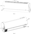
- the present invention proposes a housing, applied to an indoor unit of an air conditioner.
- the housing 10 includes:
- the indoor unit 1 includes the face frame 100 and the panel 120.
- the outer surface of the face frame 100 is provided with the panel 120.
- the air outlet 110 is formed in a lower portion of the front side of the face frame 100.
- the air outlet 110 is adjacent to the lower edge of the panel 120.
- the housing 10 further includes a front decorative strip 130 and two side decorative strips 140, and the front decorative strip 130 is mounted on the lower edge of the panel 120, two side decorative strips 140 are respectively mounted on the left and right ends of the face frame 100 respectively, and the front decorative strip 130 is connected to the side decorative strips 140.
- the front decorative strip 140 can significantly improve the decorative effect of the panel 120, especially the decorative effect of the front side of the housing 10; the two side decorative strips 130 can further significantly improve the decorative effects on the left and right sides of the housing 10.
- the front decorative strip 130 is connected to the side decorative strips 140, thereby achieving a continuous appearance.
- the indoor unit 1 presents a three-dimensional decorative effect, the overall appearance of the indoor unit 1 is significantly improved, thereby effectively enhancing the market competitiveness.
- front decorative strip 130 may be fixed on the panel 120 by welding, gluing or the like; or the front decorative strip 130 may be detachably connected to the panel 120 by a fastener connecting mode, a screw connecting mode, or the like.
- side decorative strips 140 can also be fixed to the left and right ends of the face frame 100 in various ways which do not need to be further described herein.
- the front decorative strip 130 is mounted to the lower edge of the panel 120, and the two side decorative strips 140 are mounted to the left and right ends of the face frame 100, respectively, and the front decorative strip 130 are connected with the side decorative strips 140.
- the front decorative strip 140 can significantly improve the decorative effect of the panel 120, especially the decorative effect of the front side of the housing 10; the two side decorative strips 130 can further significantly improve the decorative effects on the left and right sides of the housing 10.
- the front decorative strip 130 is connected to the side decorative strips 140, thereby achieving a continuous appearance.
- the indoor unit 1 presents a three-dimensional decorative effect, the overall appearance of the indoor unit 1 is significantly improved, thereby effectively enhancing the market competitiveness.
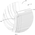
- the left and right end faces of the front decorative strip 130 are inclined rearwards, and the end faces of the side decorative strips 140 which are connected to the end faces of the front decorative strip 130 are inclined forwards.
- the front decorative strip 130 is pre-mounted on the panel 120, and the side decorative strips 140 are also pre-mounted on the face frame 100.
- end surfaces of the front decorative strip 130 and another end surfaces of the side decorative strips 140 connected with the end surfaces of the front decorative strip 130 are all defined as inclined surface, the inclined surfaces of the front decorative strip 130 are all inclined towards side decorative strips 140 along the back-front direction.
- the panel 120 is mounted to the face frame 100 along the front-back direction.
- the front decorative strip 130 can be easily connected to the side decorative strips 140, so that a interference between the front decorative strip 130 and the side decorative strip 140 can be avoided when the panel 120 is mounted to the face frame 100, thereby connecting the panel 120 with the face frame 100 easily.
- a mounting gap between the from decorative strip 130 and each side decorative strip 140 is much more small as a result of the inclined surfaces, thereby beautifying the appearance of the indoor unit 1.
- a thickness of each side decorative strip 140 is the same as that of the front decorative strip 130, thereby realizing a continuous appearance.
- a thickness of other portion of each side decorative strips 140 is gradually decreased in a direction away from the connecting portion of the side decorative strip 140.
- the front decorative strip 130 is detachably mounted on the panel 120, to facilitate the disassembly and assembly of the front decorative strip 130.
- the front decorative strip 130 is fastened and fixed to the panel 120.
- the upper surface of the front decorative strip 130 is convexly provided with a positioning element 131, and the lower edge of the panel 120 is provided with an avoiding hole 121 which is matched with the positioning element 131.
- the positioning element 131 is firstly inserted into the avoiding hole 121 for pre-locating the front decorative strip 130 into the avoiding hole 121.
- the front decorative strip 130 is fixed to the panel 120.
- the front decorative strip 130 can be mounted to the panel 120 conveniently.
- the positioning element 121 in order to mount the positioning element 131 into the avoiding hole 121 easily, is configured to extend along a length direction of the decorative strip 130, and the length of the positioning element 131 parallel to the length direction of the decorative strip 130 is gradually decreased along the protruding direction of the positioning element 131. It is provided that the positioning element 131 is tapered in its protruding direction. In this way, the positioning element 131 has a trapezoidal shape, and a protruding end of the positioning element 131 is small, so that the positioning element 131 can be easily fastened into the avoiding hole 121.
- the middle part of the decorative strip 130 is mounted to the panel 120 first.
- the end of the decorative strip 130 is provided with the positioning element 131.
- the positioning element 131 is mounted to the panel 120 first, which is much more in conformity with workers' assembly habit and conducive to the assembly of the decorative strip 130. Meanwhile, the positioning element 131 is defined at the end of the decorative strip 130, thereby achieving a good mistake proofing effect and reducing a misalignment probability.
- the housing 10 further includes two end covers 150 mounted to left and right ends of the face frame 100, and each side decorative strip 140 are disposed on an outer side of corresponding end cover 150.
- each side decorative strip 140 are disposed on an outer side of corresponding end cover 150.
- the injection model is generally used as the end cover 150.
- the side decorative strips 140 are integrally formed with the end covers 150 through an injection process; or the side decorative strips 140 are detachably mounted to the outer side of the end covers 150 respectively.
- each end cover 150 is provided with a mounting groove, the side decorative strips 140 are embedded into one corresponding mounting groove.
- the side decorative strips 140 are fastened and fixed in the mounting groove, the manufacturing difficulty of the end covers 150 is reduced, and the decorative strips 140 can be easily mounted to or detached from the end covers 150.
- each of the two side decorative strips 140 is S shaped and arranged on the outer side of one corresponding end cover 150, thereby improving the decorative effect of the side decorative strips 140.
- the indoor unit of the wall-mounted air conditioner 1 has a good appearance.
- the present invention also provides an indoor unit of a wall-mounted air conditioner 1, which includes a housing 10.
- the specific structure of the housing 10 can be referred to the above embodiments.
- the indoor unit 1 adopts all the technical solutions of the above exemplary embodiments, the indoor unit 1 at least has all of the beneficial effects of the technical solutions of the above exemplary embodiments, no need to repeat again.
Landscapes
- Engineering & Computer Science (AREA)
- Chemical & Material Sciences (AREA)
- Combustion & Propulsion (AREA)
- Mechanical Engineering (AREA)
- General Engineering & Computer Science (AREA)
- Air Filters, Heat-Exchange Apparatuses, And Housings Of Air-Conditioning Units (AREA)
- Toys (AREA)
Claims (10)
- Gehäuse (10), geeignet für eine Innenraumeinheit einer wandmontierten Klimaanlage (1), wobei das Gehäuse (10) Folgendes umfasst:einen Frontrahmen (100) aufweisend einen Luftauslass (110);eine Blende (120), die an einer Vorderseite des Frontrahmens (100) befestigt ist, wobei der Luftauslass (110) an einer unteren Kante der Blende (120) anliegt;dadurch gekennzeichnet, dass das Gehäuse (10) Folgendes umfasst:einen vorderen Zierstreifen (130), der an der unteren Kante der Blende (120) befestigt ist; undzwei seitliche Zierstreifen (140), die jeweils am linken bzw. rechten Ende des Frontrahmens (100) befestigt sind und beide mit dem vorderen Zierstreifen (130) verbunden und daran befestigt sind,wobei der vordere Zierstreifen (130) Folgendes umfasst:linke und rechte Endflächen, die beide nach hinten geneigt sind,wobei jeder der zwei seitlichen Zierstreifen (140) Folgendes umfasst:
mindestens eine Endfläche, die mit der linken Endfläche des vorderen Zierstreifens (130) oder der rechten Endfläche des vorderen Zierstreifens (130) verbunden und daran befestigt und nach vorne geneigt ist. - Gehäuse (10) gemäß Anspruch 1,
wobei eine Dicke eines Verbindungsbereichs von jedem der zwei seitlichen Zierstreifen (140) die gleiche wie die eines Verbindungsbereichs des vorderen Zierstreifens (130) entlang einer Vorne-Hinten-Richtung ist. - Gehäuse (10) gemäß einem der Ansprüche 1 bis 2,
wobei eine Dicke von jedem der zwei seitlichen Zierstreifen (140) entlang einer Richtung weg von dem Verbindungsbereich allmählich abnimmt. - Gehäuse (10) gemäß einem der Ansprüche 1 bis 3,
wobei der vordere Zierstreifen (130) an der Blende (120) befestigt und fixiert ist. - Gehäuse (10) gemäß einem der Ansprüche 1 bis 4,
wobei der vordere Zierstreifen (130) Folgendes umfasst:eine obere Fläche; undein Positionierungselement (131), das von der oberen Fläche nach oben vorsteht,wobeiein Ausweichloch (121) für das in das Ausweichloch (121) einzupassende Positionierungselement (131) in der Unterkante der Blende (120) angeordnet ist. - Gehäuse (10) gemäß einem der Ansprüche 1 bis 5, umfassend:zwei Endabdeckungen (150), die jeweils am linken und rechten Ende des Frontrahmens (100) befestigt sind,wobei jeder der zwei seitlichen Zierstreifen (140) an einer Außenseite jeder der entsprechenden Endabdeckungen (150) angeordnet ist.
- Gehäuse (10) gemäß einem der Ansprüche 1 bis 6,
wobei die Außenseite jeder der zwei Endabdeckungen (150) mit einer Befestigungsnut versehen ist, wobei jeder der zwei seitlichen Zierstreifen (140) in jede der entsprechenden Befestigungsnuten befestigt und fixiert ist. - Gehäuse (10) gemäß einem der Ansprüche 1 bis 7,
wobei jeder der zwei seitlichen Zierstreifen (140) S-förmig ist und an der Außenseite jeder der entsprechenden Endabdeckungen (150) angeordnet ist. - Gehäuse (10) gemäß Anspruch 4, umfassend:zwei Endabdeckungen (150), die jeweils am linken und rechten Ende des Frontrahmens (100) befestigt sind,wobei jeder der zwei seitlichen Zierstreifen (140) an einer Außenseite jeder der entsprechenden Endabdeckungen (150) angeordnet ist.
- Innenraumeinheit einer wandmontierten Klimaanlage (1), umfassend:
ein Gehäuse (10) wie in einem der Ansprüche 1-9 beschrieben.
Applications Claiming Priority (2)
| Application Number | Priority Date | Filing Date | Title |
|---|---|---|---|
| CN201820181649.1U CN207881163U (zh) | 2018-01-31 | 2018-01-31 | 壳体及空调挂机 |
| PCT/CN2018/109125 WO2019148880A1 (zh) | 2018-01-31 | 2018-09-30 | 壳体及空调挂机 |
Publications (3)
| Publication Number | Publication Date |
|---|---|
| EP3604966A1 EP3604966A1 (de) | 2020-02-05 |
| EP3604966A4 EP3604966A4 (de) | 2020-04-22 |
| EP3604966B1 true EP3604966B1 (de) | 2023-03-08 |
Family
ID=63510727
Family Applications (1)
| Application Number | Title | Priority Date | Filing Date |
|---|---|---|---|
| EP18903064.6A Active EP3604966B1 (de) | 2018-01-31 | 2018-09-30 | Gehäuse und wandmontierte klimaanlage |
Country Status (4)
| Country | Link |
|---|---|
| EP (1) | EP3604966B1 (de) |
| JP (1) | JP7043697B2 (de) |
| CN (1) | CN207881163U (de) |
| WO (1) | WO2019148880A1 (de) |
Families Citing this family (8)
| Publication number | Priority date | Publication date | Assignee | Title |
|---|---|---|---|---|
| CN207881163U (zh) * | 2018-01-31 | 2018-09-18 | 广东美的制冷设备有限公司 | 壳体及空调挂机 |
| CN109059240B (zh) * | 2018-10-30 | 2024-06-14 | 奥克斯空调股份有限公司 | 一种空调装饰条装配结构及空调器 |
| CN109140742B (zh) * | 2018-10-30 | 2024-06-14 | 奥克斯空调股份有限公司 | 一种空调装饰条装配结构及空调器 |
| WO2020155693A1 (zh) * | 2019-02-01 | 2020-08-06 | 广东美的制冷设备有限公司 | 壁挂式室内机及空调器 |
| CN109959144B (zh) * | 2019-04-22 | 2024-07-02 | 宁波奥克斯电气股份有限公司 | 一种空调装饰组件及空调器 |
| CN110595042A (zh) * | 2019-10-15 | 2019-12-20 | 宁波奥克斯电气股份有限公司 | 一种前面板及空调器 |
| CN116123713B (zh) * | 2021-11-15 | 2025-10-31 | 宁波奥克斯电气有限公司 | 一种面板和空调器 |
| CN114183823B (zh) * | 2021-12-10 | 2022-12-16 | 珠海格力电器股份有限公司 | 空调器 |
Family Cites Families (10)
| Publication number | Priority date | Publication date | Assignee | Title |
|---|---|---|---|---|
| JP5289076B2 (ja) * | 2009-01-26 | 2013-09-11 | 三菱電機株式会社 | 空気調和機の室内ユニット及びこれを備えた空気調和機 |
| JP2012077973A (ja) * | 2010-09-30 | 2012-04-19 | Mitsubishi Heavy Ind Ltd | 空気調和装置の室内機 |
| CN202303813U (zh) * | 2011-10-31 | 2012-07-04 | 广州松下空调器有限公司 | 空调器 |
| CN203024372U (zh) * | 2012-12-11 | 2013-06-26 | 珠海格力电器股份有限公司 | 空调器及其装饰板 |
| CN103868218B (zh) * | 2012-12-11 | 2017-07-28 | 珠海格力电器股份有限公司 | 空调器及其装饰板 |
| CN105115122B (zh) * | 2015-09-01 | 2018-11-13 | 珠海格力电器股份有限公司 | 一种出风口结构及空调器 |
| JP2017161179A (ja) * | 2016-03-10 | 2017-09-14 | 株式会社富士通ゼネラル | 空気調和機の室内機 |
| JP2017161178A (ja) * | 2016-03-10 | 2017-09-14 | 株式会社富士通ゼネラル | 空気調和機の室内機 |
| JP2018162921A (ja) * | 2017-03-27 | 2018-10-18 | 株式会社富士通ゼネラル | 空気調和機 |
| CN207881163U (zh) * | 2018-01-31 | 2018-09-18 | 广东美的制冷设备有限公司 | 壳体及空调挂机 |
-
2018
- 2018-01-31 CN CN201820181649.1U patent/CN207881163U/zh active Active
- 2018-09-30 WO PCT/CN2018/109125 patent/WO2019148880A1/zh not_active Ceased
- 2018-09-30 JP JP2019557494A patent/JP7043697B2/ja active Active
- 2018-09-30 EP EP18903064.6A patent/EP3604966B1/de active Active
Also Published As
| Publication number | Publication date |
|---|---|
| CN207881163U (zh) | 2018-09-18 |
| WO2019148880A1 (zh) | 2019-08-08 |
| JP7043697B2 (ja) | 2022-03-30 |
| JP2020517897A (ja) | 2020-06-18 |
| EP3604966A4 (de) | 2020-04-22 |
| EP3604966A1 (de) | 2020-02-05 |
Similar Documents
| Publication | Publication Date | Title |
|---|---|---|
| EP3604966B1 (de) | Gehäuse und wandmontierte klimaanlage | |
| USD413328S (en) | Remote controller combined with wireless telephone | |
| USD494866S1 (en) | Spraying head | |
| USD425036S (en) | Computer display | |
| USD446295S1 (en) | Ring-type cooling fan | |
| USD445447S1 (en) | Calculator | |
| USD506687S1 (en) | Thermostat housing | |
| USD473007S1 (en) | Lighting fixture housing edge | |
| USD480466S1 (en) | Shroud fan | |
| USD464728S1 (en) | Respiratory mask | |
| USD481112S1 (en) | Humidifier | |
| USD453014S1 (en) | Aircraft | |
| USD518600S1 (en) | Electric shaver with an attachment | |
| CN211499598U (zh) | 一种装配式装修结构组件 | |
| USD468341S1 (en) | Electronic calculator with printer | |
| USD484962S1 (en) | Humidifier | |
| USD462083S1 (en) | Electronic calculator | |
| USD461839S1 (en) | Electronic calculator | |
| USD507831S1 (en) | Nasal mask | |
| USD459384S1 (en) | Electronic calculator with printer | |
| USD483796S1 (en) | Calculator with frames | |
| USD468444S1 (en) | Windowgrid assembly | |
| USD488033S1 (en) | Icing spatula | |
| USD469364S1 (en) | Watch with rectangular face and beveled glass | |
| USD459286S1 (en) | Ducted fan aircraft |
Legal Events
| Date | Code | Title | Description |
|---|---|---|---|
| STAA | Information on the status of an ep patent application or granted ep patent |
Free format text: STATUS: THE INTERNATIONAL PUBLICATION HAS BEEN MADE |
|
| PUAI | Public reference made under article 153(3) epc to a published international application that has entered the european phase |
Free format text: ORIGINAL CODE: 0009012 |
|
| STAA | Information on the status of an ep patent application or granted ep patent |
Free format text: STATUS: REQUEST FOR EXAMINATION WAS MADE |
|
| 17P | Request for examination filed |
Effective date: 20191025 |
|
| AK | Designated contracting states |
Kind code of ref document: A1 Designated state(s): AL AT BE BG CH CY CZ DE DK EE ES FI FR GB GR HR HU IE IS IT LI LT LU LV MC MK MT NL NO PL PT RO RS SE SI SK SM TR |
|
| AX | Request for extension of the european patent |
Extension state: BA ME |
|
| A4 | Supplementary search report drawn up and despatched |
Effective date: 20200320 |
|
| RIC1 | Information provided on ipc code assigned before grant |
Ipc: F24F 1/0057 20190101ALI20200316BHEP Ipc: F24F 13/20 20060101AFI20200316BHEP |
|
| DAV | Request for validation of the european patent (deleted) | ||
| DAX | Request for extension of the european patent (deleted) | ||
| STAA | Information on the status of an ep patent application or granted ep patent |
Free format text: STATUS: EXAMINATION IS IN PROGRESS |
|
| 17Q | First examination report despatched |
Effective date: 20220413 |
|
| GRAP | Despatch of communication of intention to grant a patent |
Free format text: ORIGINAL CODE: EPIDOSNIGR1 |
|
| STAA | Information on the status of an ep patent application or granted ep patent |
Free format text: STATUS: GRANT OF PATENT IS INTENDED |
|
| INTG | Intention to grant announced |
Effective date: 20221207 |
|
| GRAS | Grant fee paid |
Free format text: ORIGINAL CODE: EPIDOSNIGR3 |
|
| GRAA | (expected) grant |
Free format text: ORIGINAL CODE: 0009210 |
|
| STAA | Information on the status of an ep patent application or granted ep patent |
Free format text: STATUS: THE PATENT HAS BEEN GRANTED |
|
| AK | Designated contracting states |
Kind code of ref document: B1 Designated state(s): AL AT BE BG CH CY CZ DE DK EE ES FI FR GB GR HR HU IE IS IT LI LT LU LV MC MK MT NL NO PL PT RO RS SE SI SK SM TR |
|
| REG | Reference to a national code |
Ref country code: CH Ref legal event code: EP Ref country code: AT Ref legal event code: REF Ref document number: 1552812 Country of ref document: AT Kind code of ref document: T Effective date: 20230315 |
|
| REG | Reference to a national code |
Ref country code: DE Ref legal event code: R096 Ref document number: 602018047131 Country of ref document: DE |
|
| REG | Reference to a national code |
Ref country code: IE Ref legal event code: FG4D |
|
| REG | Reference to a national code |
Ref country code: LT Ref legal event code: MG9D |
|
| REG | Reference to a national code |
Ref country code: NL Ref legal event code: MP Effective date: 20230308 |
|
| PG25 | Lapsed in a contracting state [announced via postgrant information from national office to epo] |
Ref country code: RS Free format text: LAPSE BECAUSE OF FAILURE TO SUBMIT A TRANSLATION OF THE DESCRIPTION OR TO PAY THE FEE WITHIN THE PRESCRIBED TIME-LIMIT Effective date: 20230308 Ref country code: NO Free format text: LAPSE BECAUSE OF FAILURE TO SUBMIT A TRANSLATION OF THE DESCRIPTION OR TO PAY THE FEE WITHIN THE PRESCRIBED TIME-LIMIT Effective date: 20230608 Ref country code: LV Free format text: LAPSE BECAUSE OF FAILURE TO SUBMIT A TRANSLATION OF THE DESCRIPTION OR TO PAY THE FEE WITHIN THE PRESCRIBED TIME-LIMIT Effective date: 20230308 Ref country code: LT Free format text: LAPSE BECAUSE OF FAILURE TO SUBMIT A TRANSLATION OF THE DESCRIPTION OR TO PAY THE FEE WITHIN THE PRESCRIBED TIME-LIMIT Effective date: 20230308 Ref country code: HR Free format text: LAPSE BECAUSE OF FAILURE TO SUBMIT A TRANSLATION OF THE DESCRIPTION OR TO PAY THE FEE WITHIN THE PRESCRIBED TIME-LIMIT Effective date: 20230308 Ref country code: ES Free format text: LAPSE BECAUSE OF FAILURE TO SUBMIT A TRANSLATION OF THE DESCRIPTION OR TO PAY THE FEE WITHIN THE PRESCRIBED TIME-LIMIT Effective date: 20230308 |
|
| REG | Reference to a national code |
Ref country code: AT Ref legal event code: MK05 Ref document number: 1552812 Country of ref document: AT Kind code of ref document: T Effective date: 20230308 |
|
| PG25 | Lapsed in a contracting state [announced via postgrant information from national office to epo] |
Ref country code: SE Free format text: LAPSE BECAUSE OF FAILURE TO SUBMIT A TRANSLATION OF THE DESCRIPTION OR TO PAY THE FEE WITHIN THE PRESCRIBED TIME-LIMIT Effective date: 20230308 Ref country code: NL Free format text: LAPSE BECAUSE OF FAILURE TO SUBMIT A TRANSLATION OF THE DESCRIPTION OR TO PAY THE FEE WITHIN THE PRESCRIBED TIME-LIMIT Effective date: 20230308 Ref country code: GR Free format text: LAPSE BECAUSE OF FAILURE TO SUBMIT A TRANSLATION OF THE DESCRIPTION OR TO PAY THE FEE WITHIN THE PRESCRIBED TIME-LIMIT Effective date: 20230609 Ref country code: FI Free format text: LAPSE BECAUSE OF FAILURE TO SUBMIT A TRANSLATION OF THE DESCRIPTION OR TO PAY THE FEE WITHIN THE PRESCRIBED TIME-LIMIT Effective date: 20230308 |
|
| PG25 | Lapsed in a contracting state [announced via postgrant information from national office to epo] |
Ref country code: SM Free format text: LAPSE BECAUSE OF FAILURE TO SUBMIT A TRANSLATION OF THE DESCRIPTION OR TO PAY THE FEE WITHIN THE PRESCRIBED TIME-LIMIT Effective date: 20230308 Ref country code: RO Free format text: LAPSE BECAUSE OF FAILURE TO SUBMIT A TRANSLATION OF THE DESCRIPTION OR TO PAY THE FEE WITHIN THE PRESCRIBED TIME-LIMIT Effective date: 20230308 Ref country code: PT Free format text: LAPSE BECAUSE OF FAILURE TO SUBMIT A TRANSLATION OF THE DESCRIPTION OR TO PAY THE FEE WITHIN THE PRESCRIBED TIME-LIMIT Effective date: 20230710 Ref country code: EE Free format text: LAPSE BECAUSE OF FAILURE TO SUBMIT A TRANSLATION OF THE DESCRIPTION OR TO PAY THE FEE WITHIN THE PRESCRIBED TIME-LIMIT Effective date: 20230308 Ref country code: CZ Free format text: LAPSE BECAUSE OF FAILURE TO SUBMIT A TRANSLATION OF THE DESCRIPTION OR TO PAY THE FEE WITHIN THE PRESCRIBED TIME-LIMIT Effective date: 20230308 Ref country code: AT Free format text: LAPSE BECAUSE OF FAILURE TO SUBMIT A TRANSLATION OF THE DESCRIPTION OR TO PAY THE FEE WITHIN THE PRESCRIBED TIME-LIMIT Effective date: 20230308 |
|
| PG25 | Lapsed in a contracting state [announced via postgrant information from national office to epo] |
Ref country code: SK Free format text: LAPSE BECAUSE OF FAILURE TO SUBMIT A TRANSLATION OF THE DESCRIPTION OR TO PAY THE FEE WITHIN THE PRESCRIBED TIME-LIMIT Effective date: 20230308 Ref country code: PL Free format text: LAPSE BECAUSE OF FAILURE TO SUBMIT A TRANSLATION OF THE DESCRIPTION OR TO PAY THE FEE WITHIN THE PRESCRIBED TIME-LIMIT Effective date: 20230308 Ref country code: IS Free format text: LAPSE BECAUSE OF FAILURE TO SUBMIT A TRANSLATION OF THE DESCRIPTION OR TO PAY THE FEE WITHIN THE PRESCRIBED TIME-LIMIT Effective date: 20230708 |
|
| REG | Reference to a national code |
Ref country code: DE Ref legal event code: R097 Ref document number: 602018047131 Country of ref document: DE |
|
| PLBE | No opposition filed within time limit |
Free format text: ORIGINAL CODE: 0009261 |
|
| STAA | Information on the status of an ep patent application or granted ep patent |
Free format text: STATUS: NO OPPOSITION FILED WITHIN TIME LIMIT |
|
| PG25 | Lapsed in a contracting state [announced via postgrant information from national office to epo] |
Ref country code: SI Free format text: LAPSE BECAUSE OF FAILURE TO SUBMIT A TRANSLATION OF THE DESCRIPTION OR TO PAY THE FEE WITHIN THE PRESCRIBED TIME-LIMIT Effective date: 20230308 Ref country code: DK Free format text: LAPSE BECAUSE OF FAILURE TO SUBMIT A TRANSLATION OF THE DESCRIPTION OR TO PAY THE FEE WITHIN THE PRESCRIBED TIME-LIMIT Effective date: 20230308 |
|
| 26N | No opposition filed |
Effective date: 20231211 |
|
| REG | Reference to a national code |
Ref country code: CH Ref legal event code: PL |
|
| PG25 | Lapsed in a contracting state [announced via postgrant information from national office to epo] |
Ref country code: LU Free format text: LAPSE BECAUSE OF NON-PAYMENT OF DUE FEES Effective date: 20230930 |
|
| REG | Reference to a national code |
Ref country code: BE Ref legal event code: MM Effective date: 20230930 |
|
| GBPC | Gb: european patent ceased through non-payment of renewal fee |
Effective date: 20230930 |
|
| PG25 | Lapsed in a contracting state [announced via postgrant information from national office to epo] |
Ref country code: LU Free format text: LAPSE BECAUSE OF NON-PAYMENT OF DUE FEES Effective date: 20230930 Ref country code: MC Free format text: LAPSE BECAUSE OF FAILURE TO SUBMIT A TRANSLATION OF THE DESCRIPTION OR TO PAY THE FEE WITHIN THE PRESCRIBED TIME-LIMIT Effective date: 20230308 |
|
| REG | Reference to a national code |
Ref country code: IE Ref legal event code: MM4A |
|
| PG25 | Lapsed in a contracting state [announced via postgrant information from national office to epo] |
Ref country code: IE Free format text: LAPSE BECAUSE OF NON-PAYMENT OF DUE FEES Effective date: 20230930 |
|
| PG25 | Lapsed in a contracting state [announced via postgrant information from national office to epo] |
Ref country code: GB Free format text: LAPSE BECAUSE OF NON-PAYMENT OF DUE FEES Effective date: 20230930 |
|
| PG25 | Lapsed in a contracting state [announced via postgrant information from national office to epo] |
Ref country code: CH Free format text: LAPSE BECAUSE OF NON-PAYMENT OF DUE FEES Effective date: 20230930 |
|
| PG25 | Lapsed in a contracting state [announced via postgrant information from national office to epo] |
Ref country code: IE Free format text: LAPSE BECAUSE OF NON-PAYMENT OF DUE FEES Effective date: 20230930 Ref country code: GB Free format text: LAPSE BECAUSE OF NON-PAYMENT OF DUE FEES Effective date: 20230930 Ref country code: FR Free format text: LAPSE BECAUSE OF NON-PAYMENT OF DUE FEES Effective date: 20230930 Ref country code: CH Free format text: LAPSE BECAUSE OF NON-PAYMENT OF DUE FEES Effective date: 20230930 |
|
| PG25 | Lapsed in a contracting state [announced via postgrant information from national office to epo] |
Ref country code: BE Free format text: LAPSE BECAUSE OF NON-PAYMENT OF DUE FEES Effective date: 20230930 |
|
| PG25 | Lapsed in a contracting state [announced via postgrant information from national office to epo] |
Ref country code: BG Free format text: LAPSE BECAUSE OF FAILURE TO SUBMIT A TRANSLATION OF THE DESCRIPTION OR TO PAY THE FEE WITHIN THE PRESCRIBED TIME-LIMIT Effective date: 20230308 |
|
| PG25 | Lapsed in a contracting state [announced via postgrant information from national office to epo] |
Ref country code: BG Free format text: LAPSE BECAUSE OF FAILURE TO SUBMIT A TRANSLATION OF THE DESCRIPTION OR TO PAY THE FEE WITHIN THE PRESCRIBED TIME-LIMIT Effective date: 20230308 |
|
| PG25 | Lapsed in a contracting state [announced via postgrant information from national office to epo] |
Ref country code: CY Free format text: LAPSE BECAUSE OF FAILURE TO SUBMIT A TRANSLATION OF THE DESCRIPTION OR TO PAY THE FEE WITHIN THE PRESCRIBED TIME-LIMIT; INVALID AB INITIO Effective date: 20180930 |
|
| PG25 | Lapsed in a contracting state [announced via postgrant information from national office to epo] |
Ref country code: HU Free format text: LAPSE BECAUSE OF FAILURE TO SUBMIT A TRANSLATION OF THE DESCRIPTION OR TO PAY THE FEE WITHIN THE PRESCRIBED TIME-LIMIT; INVALID AB INITIO Effective date: 20180930 |
|
| PGFP | Annual fee paid to national office [announced via postgrant information from national office to epo] |
Ref country code: DE Payment date: 20250923 Year of fee payment: 8 |
|
| PGFP | Annual fee paid to national office [announced via postgrant information from national office to epo] |
Ref country code: IT Payment date: 20250917 Year of fee payment: 8 |
|
| PG25 | Lapsed in a contracting state [announced via postgrant information from national office to epo] |
Ref country code: TR Free format text: LAPSE BECAUSE OF FAILURE TO SUBMIT A TRANSLATION OF THE DESCRIPTION OR TO PAY THE FEE WITHIN THE PRESCRIBED TIME-LIMIT Effective date: 20230308 |