EP3604483A1 - Gasreformierungsofen - Google Patents
Gasreformierungsofen Download PDFInfo
- Publication number
- EP3604483A1 EP3604483A1 EP18776669.6A EP18776669A EP3604483A1 EP 3604483 A1 EP3604483 A1 EP 3604483A1 EP 18776669 A EP18776669 A EP 18776669A EP 3604483 A1 EP3604483 A1 EP 3604483A1
- Authority
- EP
- European Patent Office
- Prior art keywords
- char
- gas
- filled layer
- tar
- steam
- Prior art date
- Legal status (The legal status is an assumption and is not a legal conclusion. Google has not performed a legal analysis and makes no representation as to the accuracy of the status listed.)
- Withdrawn
Links
- 239000007789 gas Substances 0.000 claims abstract description 213
- 238000000197 pyrolysis Methods 0.000 claims abstract description 69
- 238000002407 reforming Methods 0.000 claims abstract description 47
- 238000002309 gasification Methods 0.000 claims abstract description 42
- 238000011144 upstream manufacturing Methods 0.000 claims abstract description 20
- QVGXLLKOCUKJST-UHFFFAOYSA-N atomic oxygen Chemical compound [O] QVGXLLKOCUKJST-UHFFFAOYSA-N 0.000 claims abstract description 9
- 229910052760 oxygen Inorganic materials 0.000 claims abstract description 9
- 239000001301 oxygen Substances 0.000 claims abstract description 9
- 230000003647 oxidation Effects 0.000 description 30
- 238000007254 oxidation reaction Methods 0.000 description 30
- 230000003278 mimic effect Effects 0.000 description 25
- 239000002994 raw material Substances 0.000 description 13
- 238000002485 combustion reaction Methods 0.000 description 11
- MYMOFIZGZYHOMD-UHFFFAOYSA-N Dioxygen Chemical compound O=O MYMOFIZGZYHOMD-UHFFFAOYSA-N 0.000 description 8
- 229910001882 dioxygen Inorganic materials 0.000 description 8
- 239000003054 catalyst Substances 0.000 description 7
- 238000010438 heat treatment Methods 0.000 description 6
- UGFAIRIUMAVXCW-UHFFFAOYSA-N Carbon monoxide Chemical compound [O+]#[C-] UGFAIRIUMAVXCW-UHFFFAOYSA-N 0.000 description 5
- 229910002091 carbon monoxide Inorganic materials 0.000 description 5
- 238000012545 processing Methods 0.000 description 5
- 238000011084 recovery Methods 0.000 description 5
- 239000002028 Biomass Substances 0.000 description 4
- OKTJSMMVPCPJKN-UHFFFAOYSA-N Carbon Chemical compound [C] OKTJSMMVPCPJKN-UHFFFAOYSA-N 0.000 description 4
- 239000000446 fuel Substances 0.000 description 4
- 239000002699 waste material Substances 0.000 description 4
- XLYOFNOQVPJJNP-UHFFFAOYSA-N water Substances O XLYOFNOQVPJJNP-UHFFFAOYSA-N 0.000 description 4
- CURLTUGMZLYLDI-UHFFFAOYSA-N Carbon dioxide Chemical compound O=C=O CURLTUGMZLYLDI-UHFFFAOYSA-N 0.000 description 3
- 238000006243 chemical reaction Methods 0.000 description 3
- 239000000428 dust Substances 0.000 description 3
- 238000000605 extraction Methods 0.000 description 3
- 239000002737 fuel gas Substances 0.000 description 3
- 239000001257 hydrogen Substances 0.000 description 3
- 229910052739 hydrogen Inorganic materials 0.000 description 3
- 238000000746 purification Methods 0.000 description 3
- 230000000717 retained effect Effects 0.000 description 3
- 238000000629 steam reforming Methods 0.000 description 3
- 239000000126 substance Substances 0.000 description 3
- UFHFLCQGNIYNRP-UHFFFAOYSA-N Hydrogen Chemical compound [H][H] UFHFLCQGNIYNRP-UHFFFAOYSA-N 0.000 description 2
- YXFVVABEGXRONW-UHFFFAOYSA-N Toluene Natural products CC1=CC=CC=C1 YXFVVABEGXRONW-UHFFFAOYSA-N 0.000 description 2
- 239000011324 bead Substances 0.000 description 2
- 229910052799 carbon Inorganic materials 0.000 description 2
- 229910002092 carbon dioxide Inorganic materials 0.000 description 2
- 239000003610 charcoal Substances 0.000 description 2
- 239000000460 chlorine Substances 0.000 description 2
- 239000000567 combustion gas Substances 0.000 description 2
- 238000005336 cracking Methods 0.000 description 2
- 238000013461 design Methods 0.000 description 2
- 238000001514 detection method Methods 0.000 description 2
- 150000002431 hydrogen Chemical class 0.000 description 2
- 239000002440 industrial waste Substances 0.000 description 2
- 239000007788 liquid Substances 0.000 description 2
- 238000000034 method Methods 0.000 description 2
- 239000000843 powder Substances 0.000 description 2
- 238000010248 power generation Methods 0.000 description 2
- 239000010453 quartz Substances 0.000 description 2
- 238000006057 reforming reaction Methods 0.000 description 2
- VYPSYNLAJGMNEJ-UHFFFAOYSA-N silicon dioxide Inorganic materials O=[Si]=O VYPSYNLAJGMNEJ-UHFFFAOYSA-N 0.000 description 2
- ZAMOUSCENKQFHK-UHFFFAOYSA-N Chlorine atom Chemical compound [Cl] ZAMOUSCENKQFHK-UHFFFAOYSA-N 0.000 description 1
- NINIDFKCEFEMDL-UHFFFAOYSA-N Sulfur Chemical compound [S] NINIDFKCEFEMDL-UHFFFAOYSA-N 0.000 description 1
- 239000002253 acid Substances 0.000 description 1
- 230000002411 adverse Effects 0.000 description 1
- 238000007664 blowing Methods 0.000 description 1
- 239000001569 carbon dioxide Substances 0.000 description 1
- 239000000919 ceramic Substances 0.000 description 1
- 229910052801 chlorine Inorganic materials 0.000 description 1
- 239000003245 coal Substances 0.000 description 1
- 238000006298 dechlorination reaction Methods 0.000 description 1
- 230000007423 decrease Effects 0.000 description 1
- 238000006477 desulfuration reaction Methods 0.000 description 1
- 230000023556 desulfurization Effects 0.000 description 1
- 238000002474 experimental method Methods 0.000 description 1
- 239000012535 impurity Substances 0.000 description 1
- 230000007774 longterm Effects 0.000 description 1
- 229910052751 metal Inorganic materials 0.000 description 1
- 239000002184 metal Substances 0.000 description 1
- 239000003595 mist Substances 0.000 description 1
- 230000004048 modification Effects 0.000 description 1
- 238000012986 modification Methods 0.000 description 1
- 239000002574 poison Substances 0.000 description 1
- 231100000614 poison Toxicity 0.000 description 1
- 229910052573 porcelain Inorganic materials 0.000 description 1
- 239000011148 porous material Substances 0.000 description 1
- 239000011819 refractory material Substances 0.000 description 1
- 239000010802 sludge Substances 0.000 description 1
- 239000007787 solid Substances 0.000 description 1
- 229910052717 sulfur Inorganic materials 0.000 description 1
- 239000011593 sulfur Substances 0.000 description 1
- 238000004227 thermal cracking Methods 0.000 description 1
- 125000003944 tolyl group Chemical group 0.000 description 1
Images


Classifications
-
- C—CHEMISTRY; METALLURGY
- C10—PETROLEUM, GAS OR COKE INDUSTRIES; TECHNICAL GASES CONTAINING CARBON MONOXIDE; FUELS; LUBRICANTS; PEAT
- C10K—PURIFYING OR MODIFYING THE CHEMICAL COMPOSITION OF COMBUSTIBLE GASES CONTAINING CARBON MONOXIDE
- C10K3/00—Modifying the chemical composition of combustible gases containing carbon monoxide to produce an improved fuel, e.g. one of different calorific value, which may be free from carbon monoxide
- C10K3/001—Modifying the chemical composition of combustible gases containing carbon monoxide to produce an improved fuel, e.g. one of different calorific value, which may be free from carbon monoxide by thermal treatment
- C10K3/003—Reducing the tar content
-
- C—CHEMISTRY; METALLURGY
- C10—PETROLEUM, GAS OR COKE INDUSTRIES; TECHNICAL GASES CONTAINING CARBON MONOXIDE; FUELS; LUBRICANTS; PEAT
- C10K—PURIFYING OR MODIFYING THE CHEMICAL COMPOSITION OF COMBUSTIBLE GASES CONTAINING CARBON MONOXIDE
- C10K3/00—Modifying the chemical composition of combustible gases containing carbon monoxide to produce an improved fuel, e.g. one of different calorific value, which may be free from carbon monoxide
- C10K3/001—Modifying the chemical composition of combustible gases containing carbon monoxide to produce an improved fuel, e.g. one of different calorific value, which may be free from carbon monoxide by thermal treatment
- C10K3/003—Reducing the tar content
- C10K3/005—Reducing the tar content by partial oxidation
-
- C—CHEMISTRY; METALLURGY
- C10—PETROLEUM, GAS OR COKE INDUSTRIES; TECHNICAL GASES CONTAINING CARBON MONOXIDE; FUELS; LUBRICANTS; PEAT
- C10K—PURIFYING OR MODIFYING THE CHEMICAL COMPOSITION OF COMBUSTIBLE GASES CONTAINING CARBON MONOXIDE
- C10K3/00—Modifying the chemical composition of combustible gases containing carbon monoxide to produce an improved fuel, e.g. one of different calorific value, which may be free from carbon monoxide
- C10K3/001—Modifying the chemical composition of combustible gases containing carbon monoxide to produce an improved fuel, e.g. one of different calorific value, which may be free from carbon monoxide by thermal treatment
- C10K3/003—Reducing the tar content
- C10K3/006—Reducing the tar content by steam reforming
-
- C—CHEMISTRY; METALLURGY
- C10—PETROLEUM, GAS OR COKE INDUSTRIES; TECHNICAL GASES CONTAINING CARBON MONOXIDE; FUELS; LUBRICANTS; PEAT
- C10J—PRODUCTION OF PRODUCER GAS, WATER-GAS, SYNTHESIS GAS FROM SOLID CARBONACEOUS MATERIAL, OR MIXTURES CONTAINING THESE GASES; CARBURETTING AIR OR OTHER GASES
- C10J2300/00—Details of gasification processes
- C10J2300/09—Details of the feed, e.g. feeding of spent catalyst, inert gas or halogens
- C10J2300/0913—Carbonaceous raw material
- C10J2300/0916—Biomass
-
- C—CHEMISTRY; METALLURGY
- C10—PETROLEUM, GAS OR COKE INDUSTRIES; TECHNICAL GASES CONTAINING CARBON MONOXIDE; FUELS; LUBRICANTS; PEAT
- C10J—PRODUCTION OF PRODUCER GAS, WATER-GAS, SYNTHESIS GAS FROM SOLID CARBONACEOUS MATERIAL, OR MIXTURES CONTAINING THESE GASES; CARBURETTING AIR OR OTHER GASES
- C10J2300/00—Details of gasification processes
- C10J2300/09—Details of the feed, e.g. feeding of spent catalyst, inert gas or halogens
- C10J2300/0913—Carbonaceous raw material
- C10J2300/0946—Waste, e.g. MSW, tires, glass, tar sand, peat, paper, lignite, oil shale
-
- C—CHEMISTRY; METALLURGY
- C10—PETROLEUM, GAS OR COKE INDUSTRIES; TECHNICAL GASES CONTAINING CARBON MONOXIDE; FUELS; LUBRICANTS; PEAT
- C10J—PRODUCTION OF PRODUCER GAS, WATER-GAS, SYNTHESIS GAS FROM SOLID CARBONACEOUS MATERIAL, OR MIXTURES CONTAINING THESE GASES; CARBURETTING AIR OR OTHER GASES
- C10J2300/00—Details of gasification processes
- C10J2300/16—Integration of gasification processes with another plant or parts within the plant
- C10J2300/164—Integration of gasification processes with another plant or parts within the plant with conversion of synthesis gas
- C10J2300/1643—Conversion of synthesis gas to energy
- C10J2300/165—Conversion of synthesis gas to energy integrated with a gas turbine or gas motor
-
- C—CHEMISTRY; METALLURGY
- C10—PETROLEUM, GAS OR COKE INDUSTRIES; TECHNICAL GASES CONTAINING CARBON MONOXIDE; FUELS; LUBRICANTS; PEAT
- C10J—PRODUCTION OF PRODUCER GAS, WATER-GAS, SYNTHESIS GAS FROM SOLID CARBONACEOUS MATERIAL, OR MIXTURES CONTAINING THESE GASES; CARBURETTING AIR OR OTHER GASES
- C10J2300/00—Details of gasification processes
- C10J2300/16—Integration of gasification processes with another plant or parts within the plant
- C10J2300/1671—Integration of gasification processes with another plant or parts within the plant with the production of electricity
- C10J2300/1675—Integration of gasification processes with another plant or parts within the plant with the production of electricity making use of a steam turbine
-
- C—CHEMISTRY; METALLURGY
- C10—PETROLEUM, GAS OR COKE INDUSTRIES; TECHNICAL GASES CONTAINING CARBON MONOXIDE; FUELS; LUBRICANTS; PEAT
- C10J—PRODUCTION OF PRODUCER GAS, WATER-GAS, SYNTHESIS GAS FROM SOLID CARBONACEOUS MATERIAL, OR MIXTURES CONTAINING THESE GASES; CARBURETTING AIR OR OTHER GASES
- C10J2300/00—Details of gasification processes
- C10J2300/18—Details of the gasification process, e.g. loops, autothermal operation
- C10J2300/1861—Heat exchange between at least two process streams
- C10J2300/1884—Heat exchange between at least two process streams with one stream being synthesis gas
-
- C—CHEMISTRY; METALLURGY
- C10—PETROLEUM, GAS OR COKE INDUSTRIES; TECHNICAL GASES CONTAINING CARBON MONOXIDE; FUELS; LUBRICANTS; PEAT
- C10J—PRODUCTION OF PRODUCER GAS, WATER-GAS, SYNTHESIS GAS FROM SOLID CARBONACEOUS MATERIAL, OR MIXTURES CONTAINING THESE GASES; CARBURETTING AIR OR OTHER GASES
- C10J2300/00—Details of gasification processes
- C10J2300/18—Details of the gasification process, e.g. loops, autothermal operation
- C10J2300/1861—Heat exchange between at least two process streams
- C10J2300/1892—Heat exchange between at least two process streams with one stream being water/steam
Definitions
- the present invention relates to a gas reforming furnace.
- Gasification of carbon-containing raw materials such as biomass has conventionally been performed.
- the raw material is cracked by heat at a temperature of 500 to 800°C in a gasification furnace to generate a pyrolysis gas.
- the pyrolysis gas contains not only gas but also other substances such as tar vapor and powdered char.
- the pyrolysis gas is transmitted to a downstream gas reforming furnace. Inside the gas reforming furnace, a high temperature condition at 1000°C or above is kept by partial combustion caused by oxygen supply, heating with a high-temperature gas, or heating with a heater, and water steam is blown into the furnace.
- tar and char contained in the pyrolysis gas are reformed with steam and converted to a fuel gas such as hydrogen (H2) or carbon monoxide (CO).
- a fuel gas such as hydrogen (H2) or carbon monoxide (CO).
- the reformed pyrolysis gas is subjected to, for example, impurity removal in a gas purifier and then used for power generation in an internal combustion engine such as a gas engine.
- a gasification unit includes a first accumulator that temporarily accumulates char flowing downwardly from a thermal cracking unit and guides the char downwardly, a first oxidation gas supply part that introduces an oxidation gas such as air into a downflow passage that communicates with the first accumulator, a second accumulator that temporarily accumulates char flowing downwardly from the downflow passage, a gas extraction port formed at the top of the second accumulator, and a second oxidation gas supply part that introduces an oxidation gas such as air into the second accumulator.
- a pyrolysis gas with a tar content flows through the downflow passage toward the gas extraction port.
- the air supplied from the first oxidation gas supply part causes combustion reactions of the char and the pyrolysis gas, and this results in a rise in the temperature of the downflow passage. Accordingly, the tar contained in the pyrolysis gas is cracked by heat and gasified.
- the char flowing downwardly into the second accumulator causes combustion reactions with the air supplied from the second oxidation gas supply part, and this produces a combustion gas composed primarily of carbon dioxide and steam. The combustion gas reacts with the char when moving upward toward the gas extraction port and generates carbon monoxide and hydrogen.
- Japanese Patent Application Laid-Open No. 2007-231063 discloses a gasification apparatus for gasifying char and cracking tar by passing a pyrolysis gas through a char filled layer in a fixed-bed gasification furnace that accumulates the char filled layer at the bottom.
- the apparatus also includes an air nozzle for ejecting compressed air into the char filled layer, and prevents the occurrence of blow-by in the char filled layer by controlling the air nozzle on the basis of temperatures upstream and downstream of the char filled layer.
- the tar in the pyrolysis gas may not be cracked sufficiently inside the furnace. In this case, the remaining tar may adversely affect processing performed in the gas purifier and power generation in the gas engine. Thus, there is demand for techniques for significantly reducing the concentration of tar in the pyrolysis gas.
- the present invention is intended for a gas reforming furnace for reforming a pyrolysis gas supplied from a gasification furnace, and it is an object of the present invention to significantly reduce the concentration of tar in the pyrolysis gas.
- the gas reforming furnace includes a furnace body forming a flow path for the pyrolysis gas, a filled layer retainer provided in the flow path and retaining a char filled layer filled with char, a tar combustor that supplies an oxygen-containing gas to the pyrolysis gas in a space upstream of the char filled layer in the flow path to burn tar contained in the pyrolysis gas before the pyrolysis gas passes through the char filled layer, and a steam ejector that ejects steam from an ejection port provided inside the char filled layer or in proximity to the char filled layer.
- the concentration of tar in the pyrolysis gas can be reduced significantly.
- the filled layer retainer may include a retaining member that has a plurality of holes and retains the char filled layer from underside.
- the gas reforming furnace may further include a char supply part that supplies char to the filled layer retainer, a layer-thickness acquisition part that acquires a thickness of the char filled layer, and a controller that controls an amount of char supplied by the char supply part, on the basis of the thickness.
- a length of the tar combustor from a supply position of the oxygen-containing gas to a surface of the char filled layer in a direction of flow of the pyrolysis gas may be greater than the thickness of the char filled layer.
- a temperature in a space downstream of the char filled layer in the flow path may be lower than a temperature in the char filled layer.
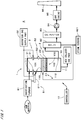
- Fig. 1 illustrates a configuration of a gasification system 8 according to an embodiment of the present invention.
- the gasification system 8 includes a gasification furnace 81, a gas reforming furnace 1, a boiler 82, a gas purifier 83, an induced draft fan 84, a gas engine 85, and a smokestack 86.
- the gasification system 8 forms an overall flow path that passes through the gasification furnace 81, the gas reforming furnace 1, the boiler 82, the gas purifier 83, the induced draft fan 84, the gas engine 85, and the smokestack 86 in the order mentioned.
- By driving the induced draft fan 84 a later-described pyrolysis gas generated in the gasification furnace 81 flows toward the smokestack 86 through the overall flow path.
- the gasification furnace 81 is, for example, a kiln-type gasification furnace, a fixed-bed gasification furnace, or a fluidized-bed gasification furnace, and wastes or biomass (hereinafter, simply referred to as "raw materials") are input in the gasification furnace 81.
- the raw materials include non-industrial wastes, industrial wastes, sludge, and woody biomass.
- the raw materials are cracked and gasified by being heated at a temperature of, for example, 400 to 800°C. This generates a pyrolysis gas.
- the pyrolysis gas contains not only gas but also other substances such as tar vapor and powdered char.
- the pyrolysis gas is supplied to the gas reforming furnace 1.
- a char recovery part (not shown) is provided and recovers char that is not included in the pyrolysis gas.
- the char that has been recovered (hereinafter, referred to as "recovered char") is supplied via a later-described screw feeder 511 into a furnace body 11 of the gas reforming furnace 1.
- the gas reforming furnace 1 performs, for example, reforming of carbon-containing non-gas components such as tar and char contained in the pyrolysis gas.
- the configuration of the gas reforming furnace 1 will be described later.
- the pyrolysis gas reformed by the gas reforming furnace 1 (hereinafter referred to as "reformed gas") flows into the boiler 82.
- the temperature of the reformed gas drops as a result of heat exchange with circulating water that circulates inside the boiler 82.
- the reformed gas flows from the boiler 82 into the gas purifier 83.
- the gas purifier 83 performs purification processing such as removal of dust and mist, dechlorination, and desulfurization on the reformed gas.
- the reformed gas that has undergone the purification processing has a temperature of approximately 50°C, for example, and is supplied to the gas engine 85 via the induced draft fan 84.
- the gas engine 85 generates electric power using the reformed gas as a fuel.
- An exhaust gas obtained by burning the reformed gas in the gas engine 85 is exhausted to the atmosphere through the smokestack 86.
- the circulating water in the boiler 82 turns into steam as a result of heat exchange with the reformed gas.
- Part of the steam is supplied to a later-described steam ejector 4 of the gas reforming furnace 1.
- the remaining steam is used to drive a steam turbine 821 and thereafter returned to the inside of the boiler 82 to serve as the circulating water.
- the aforementioned steam may be supplied to the gasification furnace 81 and used to heat the raw materials.
- the gas reforming furnace 1 includes the furnace body 11, a filled layer retainer 2, a char supply part 51, a layer-thickness acquisition part 52, a tar combustor 3, the steam ejector 4, and a controller 10.
- the controller 10 performs overall control of the gas reforming furnace 1.
- the controller 10 may perform overall control of the gasification system 8.
- the furnace body 11 has, for example, a generally cylindrical shape.
- One end portion of the furnace body 11 has an inlet 111 connected to the gasification furnace 81.
- the other end portion has an outlet 112 connected to the boiler 82.
- the pyrolysis gas from the gasification furnace 81 flows through the inlet 111 into the furnace body 11.
- the pyrolysis gas flows through the inside of the furnace body 11 toward the outlet 112 and flows out to the boiler 82 through the outlet 112. In this way, the furnace body 11 forms a flow path 100 for the pyrolysis gas.
- the shape of the furnace body 11 may be appropriately changed and may, for example, be a U-shape.
- the filled layer retainer 2 includes a plate-like retaining member 21 provided in the flow path 100.
- the retaining member 21 extends approximately perpendicular to the direction of flow of the pyrolysis gas from the inlet 111 to the outlet 112 (hereinafter, referred to as a "gas flow direction") and is connected to the entire periphery of the side wall of the furnace body 11. In the present embodiment, the gas flow direction is parallel to the vertical direction.
- the retaining member 21 has a plurality (large number) of uniformly dispersed holes, and the pyrolysis gas passes through these holes.
- the retaining member 21 is made of, for example, ceramics, porcelain, a refractory material, concrete, or a metal.
- char is accumulated.
- the char filled layer 22 filled with char is provided on the retaining member 21.
- the char filled layer 22 extends over the entire upper face of the retaining member 21.
- the char filled layer 22 is retained from the underside by the retaining member 21.
- the char supply part 51 includes the screw feeder 511.
- One end of the screw feeder 511 is connected to the char recovery part of the gasification furnace 81.
- the other end of the screw feeder 511 is connected to the furnace body 11 of the gas reforming furnace 1.
- the furnace body 11 has a char supply port 113 between the filled layer retainer 2 and the inlet 111.
- the controller 10 controls the screw feeder 511 so as to adjust the supply amount of the recovered char (feed speed of the recovered char).
- the char supply part 51 may include a powder feeder such as a table feeder other than the screw feeder 511 and supply the recovered char via a chute to the filled layer retainer 2.
- a powder feeder such as a table feeder other than the screw feeder 511
- the bottom of the gasification furnace 81 may be connected to the upper portion of the furnace body 11 so that the recovered char can simply drop from the bottom and be supplied to the filled layer retainer 2.
- a mechanism e.g., gate
- adjusting the amount of the recovered char that drops from the bottom of the gasification furnace 81 may be provided.
- the layer-thickness acquisition part 52 includes a level sensor 521.
- the level sensor 521 is of a laser type and detects a height of the surface (upper face in Fig. 1 ) of the char filled layer 22.
- a detection value obtained by the level sensor 521 is output to the controller 10.
- a distance between the retaining member 21 of the filled layer retainer 2 and the surface of the char filled layer 22, i.e., the thickness of the char filled layer 22 (hereinafter, referred to as a "layer thickness") is acquired by detecting the height of the surface of the char filled layer 22.
- the controller 10 controls the amount of recovered char supplied from the char supply part 51 to the filled layer retainer 2 on the basis of the acquired layer thickness. In actual practice, the supply amount of the recovered char is controlled so as to keep the layer thickness at a constant value.
- the char filled layer 22 has a contoured surface. This is, however, not a problem in the present processing example because a strictly exact layer thickness is not an absolute necessity.
- an accurate layer thickness may be obtained by providing a plurality of level sensors 521 and obtaining an average value of detection values obtained from these level sensors.
- the layer-thickness acquisition part 52 may acquire the layer thickness by obtaining a difference in pressure between a position upstream of the char filled layer 22 and a position downstream of the char filled layer 22.
- the recovered char may be discharged to the outside via a gate or the like, which is not shown. In this case, the recovered char discharged to the outside may be input again into the gasification furnace 81 in order to improve efficiency in the gasification of the raw materials.
- other supplementary substances such as charcoal, coal, or activated carbon may be supplied to the filled layer retainer 2.
- the ratio of char generated from the raw materials depends on the heating temperature in the gasification furnace 81.
- the heating temperature is 400°C
- the ratio of char generated from the raw materials is approximately 50%
- the heating temperature is 600°C
- the ratio of the char is approximately 30%. In this way, the ratio of char generated from the raw materials decreases as the heating temperature in the gasification furnace 81 increases.
- the tar combustor 3 includes a plurality of oxidation gas nozzles 31 and an oxidation gas supply part 32.
- the oxidation gas nozzles 31 are disposed in a space 101 upstream of the char filled layer 22 in the flow path 100 (i.e., space on the side close to the inlet 111 when viewed from the char filled layer 22; hereinafter simply referred to as an "upstream space 101").
- the oxidation gas supply part 32 supplies an oxygen-containing gas (hereinafter, referred to as an "oxidation gas”) to the oxidation gas nozzles 31.
- the oxidation gas is, for example, air.
- the oxidation gas may be oxygen itself.
- the oxidation gas supplied from the oxidation gas supply part 32 is ejected into the upstream space 101 by the oxidation gas nozzles 31.
- the oxidation gas nozzles 31 may be provided on the side wall of the furnace body 11 in multiple stages in the gas flow direction. As another alternative, the oxidation gas nozzles 31 may be provided in the upper face portion of the furnace body 11.
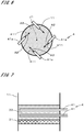
- Figs. 2 and 3 illustrate a configuration of the steam ejector 4.
- Fig. 2 illustrates a section of the furnace body 11 that is perpendicular to the gas flow direction at a position of a later-described steam pipe 41 (section viewed from the inlet 111), and
- Fig. 3 illustrates a section of the furnace body 11 that is parallel to the gas flow direction.
- the steam ejector 4 includes the steam pipe 41, and the steam supplied from the boiler 82 flows through the steam pipe 41.
- the steam pipe 41 has a plurality of folded portions folded into U-shapes in a plane perpendicular to the gas flow direction. The folded portions are disposed inside the furnace body 11, and more specifically, inside the char filled layer 22.
- a portion of the steam pipe 41 that is disposed inside the furnace body 11 has a plurality of ejection ports 411.
- the ejection ports 411 are open on the opposite side to the retaining member 21, i.e., open toward the upstream space 101.
- the steam ejector 4 ejects steam from the ejection ports 411.
- the temperature of the steam is, for example, approximately 300°C.
- the ejection direction of the steam from each ejection port 411 is indicated by an arrow with the reference sign A1.
- the length of the portion of the steam pipe 41 that is disposed inside the furnace body 11 is preferably greater than or equal to the diameter of the furnace body 11, and more preferably greater than or equal to two times the diameter of the furnace body 11. This makes it easy to dispersively eject steam over a wide range of a plane perpendicular to the gas flow direction.
- the length of this portion is, for example, less than or equal to 10 times the diameter of the furnace body 11.
- the ejection ports 411 may be open toward the retaining member 21.
- the steam supplied to the steam pipe 41 may be generated using heat of the exhaust gas from the gas engine 85 or an external heat source.
- the pyrolysis gas supplied from the inlet 111 to the inside of the furnace body 11 flows toward the char filled layer 22 in the upstream space 101.
- an oxidation gas is supplied to the pyrolysis gas by the oxidation gas nozzles 31, and not only the gas contained in the pyrolysis gas but also tar vapor are partially combusted.
- Continuous partial combustion of the pyrolysis gas allows the upstream space 101 to be kept at a high temperature, and the temperature in the upstream space 101 is, for example, in the range of 800 to 1200°C.
- the tar combustor 3 burns the tar contained in the pyrolysis gas and reduces the concentration of tar before the pyrolysis gas reaches the char filled layer 22.
- the tar combustor 3 may also cause other reactions in addition to the combustion reactions.
- the length of the tar combustor 3 from the supply position of the oxidation gas (here, the oxidation gas nozzle 31 that is located farthest from the char filled layer 22) to the surface of the char filled layer 22 in the gas flow direction is preferably greater than the thickness of the char filled layer 22.
- the position of the surface of the char filled layer 22 is, for example, an averaged position of this surface.
- the length of the tar combustor 3 is greater than or equal to 1.5 times the thickness of the char filled layer 22.
- the length of the tar combustor 3 is, for example, less than or equal to 10 times the thickness of the char filled layer 22.
- the length of the tar combustor 3 may be less than or equal to the thickness of the char filled layer 22.
- the pyrolysis gas that has reached the char filled layer 22 flows through the interstices between pieces of recovery char in the char filled layer 22 and the holes of the retaining member 21 to a space 102 downstream of the char filled layer 22 in the flow path 100 (space on the side close to the outlet 112 when viewed from the char filled layer 22; hereinafter simply referred to as a "downstream space 102").
- a space 102 downstream of the char filled layer 22 in the flow path 100 space on the side close to the outlet 112 when viewed from the char filled layer 22; hereinafter simply referred to as a "downstream space 102"
- tar remaining in the pyrolysis gas and powdered char are collected (trapped) in, for example, pores of the recovery char in the char filled layer 22.
- the temperatures of the char filled layer 22 and the pyrolysis gas flowing in the char filled layer 22 become high due to the combustion of the pyrolysis gas in the upstream space 101.
- steam is ejected vigorously (e.g., at a flow velocity higher than the flow velocity of the pyrolysis gas) from the ejection ports 411 (see Fig. 2 ) of the steam ejector 4 toward the recovered char in the char filled layer 22.
- the tar and the powdered char, which are collected in the recovered char, and the recovered char itself are converted (reformed) to a fuel gas such as hydrogen or carbon monoxide by steam reforming reaction.
- the recovered char accelerates the reforming reaction of the tar. That is, the recovered char can be regarded as playing a role as a catalyst.
- the reformed pyrolysis gas i.e., reformed gas
- no oxidation gas is supplied to the char filled layer 22 and the downstream space 102, and therefore no combustion reactions occur therein.
- the steam reforming reaction of the tar or the like is an endothermic reaction. Accordingly, the temperature in the downstream space 102 becomes, for example, less than 1200°C, which is lower than the temperatures in the upstream space 101 and the char filled layer 22.
- the char filled layer 22 is refilled with new recovered char by the char supply part 51.
- residuals that induce no reforming reactions in the char filled layer 22 residuals that are smaller in size than the holes of the retaining member 21 drop downwardly from these holes. At the bottom of the furnace body 11, such residuals are collected by an ash collecting part 19.
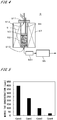
- FIG. 4 illustrates a configuration of an experimental apparatus 9.
- a tubular container 91 with a bottom is filled with quartz beads 92, and mimic char is accumulated on the quartz beads 92 to form a char filled layer 93.
- the mimic char is charcoal powder.
- Disposed in the periphery of the tubular container 91 is an electric heater 97, and the tubular container 91 is heated to 1100°C.
- the tubular container 91 has a lid member 911 attached to the top, and the lid member 911 has an inlet 912. Through the inlet 912, mimic gas, mimic tar, steam, an oxygen gas, and mimic char can be supplied into the tubular container 91.
- the mimic gas contains components that exist in an actual pyrolysis gas, and the mimic gas is a mixed gas of N 2 , CO 2 , H 2 , CO, and CH 4 .
- the mimic tar is toluene.
- the oxygen gas is used for partial combustion of mimic gas or the like.
- the lid member 911 includes a nozzle 94 (hereinafter, referred to as an "in-layer nozzle 94").
- An ejection port at the tip end of the in-layer nozzle 94 is located inside the char filled layer 93, and more specifically, in the center of the char filled layer 93 in the up-down direction. Steam can be supplied to the in-layer nozzle 94.
- the lower end of the tubular container 91 has an outlet 913 for mimic gas or the like. Gas exhausted from the outlet 913 is introduced into a detector 95 (gas chromatograph) via a char collector 951 so as to detect the concentration of mimic tar in the gas.
- the gas reforming furnace 1 includes the tar combustor 3, the filled layer retainer 2, and the steam ejector 4.
- the tar combustor 3 burns the tar contained in the pyrolysis gas before the pyrolysis gas passes through the char filled layer 22.
- the char filled layer 22 collects the tar remaining in the pyrolysis gas, and the steam ejector 4 ejects steam from the ejection ports 411 provided inside the char filled layer 22, so that the tar and the char are reformed with the steam in the char filled layer 22.
- This enables appropriately reforming the pyrolysis gas and appropriately gasifying the recovered char, as well as significantly reducing the concentration of tar in the pyrolysis gas.
- the load of the gas purification processing on the gas purifier 83 can be reduced, and the occurrence of troubles due to the remaining tar in the gas engine 85 can be reduced.
- the recovered char generated in the gasification furnace 81 is used to form the char filled layer 22, and the char filled layer 22 is used for tar reforming.
- the recovered char of the char filled layer 22 is also reformed (gasified).
- the energy of the raw materials can be used without waste.
- running costs of the gas reforming furnace 1 can also be reduced.
- the thickness of the char filled layer 22 can be kept constant with high precision by controlling the amount of recovered char supplied by the char supply part 51 on the basis of the layer thickness acquired by the layer-thickness acquisition part 52. As a result, it is possible to appropriately maintain the space (upstream space 101) necessary for tar combustion and the thickness of the char filled layer 22 required for tar collection and to stably reduce the concentration of tar in the pyrolysis gas. Also, the char filled layer 22 can be retained appropriately since the filled layer retainer 2 includes the retaining member 21 having a plurality of holes.
- Fig. 6 illustrates another example of the steam ejector 4.
- the steam ejector 4 in Fig. 6 includes a plurality of steam nozzles 41a.
- the steam nozzles 41a are arranged at equiangular intervals in the circumferential direction about a central axis J1 of the furnace body 11 in a plane perpendicular to the gas flow direction.
- Each steam nozzle 41a has an ejection port 411 at the tip end.
- the ejection direction of the steam from each steam nozzle 41a is indicated by an arrow with the reference sign A2.
- FIG. 6 illustrates another example of the steam ejector 4.
- the steam ejector 4 in Fig. 6 includes a plurality of steam nozzles 41a.
- the steam nozzles 41a are arranged at equiangular intervals in the circumferential direction about a central axis J1 of the furnace body 11 in a plane perpendicular to the gas flow direction.
- Each steam nozzle 41a has
- the ejection directions of the steam nozzles 41a are set such that the trajectories of the steam ejected from the steam nozzles 41a form parallel crosses.
- the steam ejector 4 has three or more ejection ports 411 that are disposed at the same position in the gas flow direction as illustrated in Figs. 2 and 6 .
- Fig. 7 illustrates another example of the steam ejector 4.
- the steam ejector 4 in Fig. 7 includes a plurality of (two in Fig. 7 ) steam pipes 41 provided with an interval therebetween in the gas flow direction. This enables supplying steam over a wide range in the gas flow direction within the char filled layer 22. As a result, the concentration of tar in the pyrolysis gas can be further reduced.
- a plurality of steam nozzles 41a may be disposed with an interval therebetween in the gas flow direction.
- the ejection ports 411 of the steam ejector 4 may be provided outside the char filled layer 22 as long as the ejection ports 411 are located in proximity to the char filled layer 22.
- the steam pipe 41 is provided at a position slightly spaced from the surface of the char filled layer 22.
- This steam pipe 41 has a plurality of ejection ports 411 that are open downwardly, i.e., toward the char filled layer 22, in Fig. 8 .
- Steam from the ejection ports 411 is ejected to the surface of the char filled layer 22 (see arrows A3 that indicate the ejection directions of the steam). In this case as well, tar and char can be reformed efficiently in the char filled layer 22.
- the distance between the ejection ports 411 disposed in proximity to the char filled layer 22 and the surface of the char filled layer 22 is preferably less than or equal to one-third of the distance between the ejection ports 411 and the oxidation gas nozzle 31, and more preferably less than or equal to one-fifth of that distance.
- steam can be regarded as being ejected directly from the ejection ports 411 to the char filled layer 22.
- the gasification system 8 and the gas reforming furnace 1 described above can be modified in various ways.
- steam may also be introduced at a position distant from the char filled layer 22 in the upstream space 101.
- the flow rate of the oxidation gas is preferably higher than the flow rate of the steam, and more preferably no steam is introduced, in order to appropriately burn the tar contained in the pyrolysis gas in the upstream space 101.
- an oxidation gas may be ejected inside or in proximity to the char filled layer 22, in addition to steam.
- the flow rate of the steam is preferably higher than the flow rate of the oxidation gas, and more preferably no oxidation gas is ejected, in order to appropriately reform the tar with the steam in the char filled layer 22.
- At least one of the ejection ports 411 of the steam ejector 4 is preferably located at a position spaced by a distance greater than or equal to one-third of the thickness of the char filled layer 22 from the retaining member 21 toward the upstream side, and more preferably located at a position spaced by a distance greater than or equal to a half of that thickness.
- the retaining member 21 of the filled layer retainer 2 may be provided in proximity to the outlet 112.
- the char filled layer 22 may be retained at the bottom of the furnace body 11. In this case, the bottom plays a role as the filled layer retainer 2. The pyrolysis gas that has passed through the char filled layer 22 is exhausted out of the furnace body 11 through the outlet 112 provided at the bottom.
- the reformed pyrolysis gas reformed by the gas reforming furnace 1 may be used in a gas turbine or a fuel cell (e.g., solid oxide fuel cell (SOFC)).
- the reformed gas may be used as a fuel gas in various applications, and may also be used as a liquid fuel after conversion to a liquid.
Landscapes
- Chemical & Material Sciences (AREA)
- Engineering & Computer Science (AREA)
- Combustion & Propulsion (AREA)
- Physics & Mathematics (AREA)
- Thermal Sciences (AREA)
- Chemical Kinetics & Catalysis (AREA)
- General Chemical & Material Sciences (AREA)
- Oil, Petroleum & Natural Gas (AREA)
- Organic Chemistry (AREA)
- Industrial Gases (AREA)
Applications Claiming Priority (2)
| Application Number | Priority Date | Filing Date | Title |
|---|---|---|---|
| JP2017070632A JP6696929B2 (ja) | 2017-03-31 | 2017-03-31 | ガス改質炉 |
| PCT/JP2018/011753 WO2018181012A1 (ja) | 2017-03-31 | 2018-03-23 | ガス改質炉 |
Publications (1)
| Publication Number | Publication Date |
|---|---|
| EP3604483A1 true EP3604483A1 (de) | 2020-02-05 |
Family
ID=63677517
Family Applications (1)
| Application Number | Title | Priority Date | Filing Date |
|---|---|---|---|
| EP18776669.6A Withdrawn EP3604483A1 (de) | 2017-03-31 | 2018-03-23 | Gasreformierungsofen |
Country Status (5)
| Country | Link |
|---|---|
| EP (1) | EP3604483A1 (de) |
| JP (1) | JP6696929B2 (de) |
| CN (1) | CN110475844A (de) |
| PH (1) | PH12019502228A1 (de) |
| WO (1) | WO2018181012A1 (de) |
Family Cites Families (8)
| Publication number | Priority date | Publication date | Assignee | Title |
|---|---|---|---|---|
| JP2004275901A (ja) * | 2003-03-17 | 2004-10-07 | Kurimoto Ltd | 植物性有機物の熱分解ガス化装置および熱分解ガス化装置を用いた発電設備 |
| JP4790412B2 (ja) | 2005-12-28 | 2011-10-12 | 中外炉工業株式会社 | バイオマスガス化装置 |
| JP4696970B2 (ja) | 2006-02-28 | 2011-06-08 | 日立造船株式会社 | ガス化装置におけるチャー充填層吹抜防止装置 |
| JP2009057497A (ja) * | 2007-08-31 | 2009-03-19 | Bio Coke Lab Co Ltd | ガス化方法、ガス生成装置及びガス化装置 |
| CN101230296A (zh) * | 2007-12-28 | 2008-07-30 | 中国科学院广州能源研究所 | 生物质粗燃气制备合成气的重整反应器和方法 |
| JP5688636B2 (ja) * | 2010-11-08 | 2015-03-25 | 松下 靖治 | ガス化炉及びガス化システム |
| JP6055586B2 (ja) * | 2010-11-08 | 2016-12-27 | 松下 靖治 | 改質装置 |
| CN105754662B (zh) * | 2016-03-17 | 2019-01-04 | 华东理工大学 | 一种生物质裂解气与生物质炭气固同步气化制取富氢气体的方法 |
-
2017
- 2017-03-31 JP JP2017070632A patent/JP6696929B2/ja active Active
-
2018
- 2018-03-23 CN CN201880021115.5A patent/CN110475844A/zh active Pending
- 2018-03-23 WO PCT/JP2018/011753 patent/WO2018181012A1/ja not_active Ceased
- 2018-03-23 EP EP18776669.6A patent/EP3604483A1/de not_active Withdrawn
-
2019
- 2019-09-26 PH PH12019502228A patent/PH12019502228A1/en unknown
Also Published As
| Publication number | Publication date |
|---|---|
| WO2018181012A1 (ja) | 2018-10-04 |
| JP2018172481A (ja) | 2018-11-08 |
| CN110475844A (zh) | 2019-11-19 |
| PH12019502228A1 (en) | 2020-06-29 |
| JP6696929B2 (ja) | 2020-05-20 |
Similar Documents
| Publication | Publication Date | Title |
|---|---|---|
| CA2710732C (en) | Method and apparatus to produce synthetic gas | |
| US20110104575A1 (en) | Generating clean syngas from biomass | |
| SE0801266A0 (sv) | Tvåstegsförgasare som använder förupphettad ånga av hög temperatur | |
| JP2010521544A (ja) | ガス化装置 | |
| CN105026725A (zh) | 原料气化方法及设备 | |
| US20250256255A1 (en) | System for the neutral/negative co2 production of syngas from solid fuels with high hydrogen content for uses at high temperature | |
| US10851319B2 (en) | Gasification system and method | |
| KR101858776B1 (ko) | 간접가열 가스화 동안 코크스를 생산하기 위한 방법 및 장치 | |
| EP3604483A1 (de) | Gasreformierungsofen | |
| JP6996991B2 (ja) | ガス化システム | |
| US20160200991A1 (en) | Process and plant for at least partial gasification of solid organic feed material | |
| CN108368440B (zh) | 气化装置、气化装置的控制装置及方法、气化复合发电设备 | |
| JP7118341B2 (ja) | 水素製造装置 | |
| JP5762109B2 (ja) | タール分解方法およびタール分解設備 | |
| EP3583193B1 (de) | Getrennte kammern pyrolysis-ofen | |
| EP3305875B1 (de) | Reaktordurchflusssteuerung | |
| JP7509952B2 (ja) | ガス化システム | |
| US20250153129A1 (en) | Plant, device and process | |
| KR102465670B1 (ko) | 다수의 드래프트 튜브를 갖는 순환 유동층 가스화 장치 및 방법 | |
| CN110446774B (zh) | 气化装置 | |
| JP2018193507A (ja) | ガス改質炉および熱分解ガス改質方法 | |
| CZ304134B6 (cs) | Zarízení pro zplynování ruzných druhu vstupní suroviny |
Legal Events
| Date | Code | Title | Description |
|---|---|---|---|
| PUAI | Public reference made under article 153(3) epc to a published international application that has entered the european phase |
Free format text: ORIGINAL CODE: 0009012 |
|
| 17P | Request for examination filed |
Effective date: 20191025 |
|
| AK | Designated contracting states |
Kind code of ref document: A1 Designated state(s): AL AT BE BG CH CY CZ DE DK EE ES FI FR GB GR HR HU IE IS IT LI LT LU LV MC MK MT NL NO PL PT RO RS SE SI SK SM TR |
|
| AX | Request for extension of the european patent |
Extension state: BA ME |
|
| DAV | Request for validation of the european patent (deleted) | ||
| DAX | Request for extension of the european patent (deleted) | ||
| STAA | Information on the status of an ep patent application or granted ep patent |
Free format text: STATUS: THE APPLICATION HAS BEEN WITHDRAWN |
|
| 18W | Application withdrawn |
Effective date: 20201009 |