EP3604072B1 - Hebbare tragvorrichtung - Google Patents
Hebbare tragvorrichtung Download PDFInfo
- Publication number
- EP3604072B1 EP3604072B1 EP18187294.6A EP18187294A EP3604072B1 EP 3604072 B1 EP3604072 B1 EP 3604072B1 EP 18187294 A EP18187294 A EP 18187294A EP 3604072 B1 EP3604072 B1 EP 3604072B1
- Authority
- EP
- European Patent Office
- Prior art keywords
- support means
- support
- pocket wagon
- wagon
- Prior art date
- Legal status (The legal status is an assumption and is not a legal conclusion. Google has not performed a legal analysis and makes no representation as to the accuracy of the status listed.)
- Active
Links
Images


Classifications
-
- B—PERFORMING OPERATIONS; TRANSPORTING
- B60—VEHICLES IN GENERAL
- B60P—VEHICLES ADAPTED FOR LOAD TRANSPORTATION OR TO TRANSPORT, TO CARRY, OR TO COMPRISE SPECIAL LOADS OR OBJECTS
- B60P1/00—Vehicles predominantly for transporting loads and modified to facilitate loading, consolidating the load, or unloading
- B60P1/44—Vehicles predominantly for transporting loads and modified to facilitate loading, consolidating the load, or unloading having a loading platform thereon raising the load to the level of the load-transporting element
-
- B—PERFORMING OPERATIONS; TRANSPORTING
- B61—RAILWAYS
- B61D—BODY DETAILS OR KINDS OF RAILWAY VEHICLES
- B61D3/00—Wagons or vans
- B61D3/16—Wagons or vans adapted for carrying special loads
- B61D3/18—Wagons or vans adapted for carrying special loads for vehicles
-
- B—PERFORMING OPERATIONS; TRANSPORTING
- B60—VEHICLES IN GENERAL
- B60P—VEHICLES ADAPTED FOR LOAD TRANSPORTATION OR TO TRANSPORT, TO CARRY, OR TO COMPRISE SPECIAL LOADS OR OBJECTS
- B60P1/00—Vehicles predominantly for transporting loads and modified to facilitate loading, consolidating the load, or unloading
- B60P1/44—Vehicles predominantly for transporting loads and modified to facilitate loading, consolidating the load, or unloading having a loading platform thereon raising the load to the level of the load-transporting element
- B60P1/4485—Attaching the complete loading platform unit to the vehicle
-
- B—PERFORMING OPERATIONS; TRANSPORTING
- B60—VEHICLES IN GENERAL
- B60P—VEHICLES ADAPTED FOR LOAD TRANSPORTATION OR TO TRANSPORT, TO CARRY, OR TO COMPRISE SPECIAL LOADS OR OBJECTS
- B60P3/00—Vehicles adapted to transport, to carry or to comprise special loads or objects
- B60P3/06—Vehicles adapted to transport, to carry or to comprise special loads or objects for carrying vehicles
- B60P3/08—Multilevel-deck construction carrying vehicles
-
- B—PERFORMING OPERATIONS; TRANSPORTING
- B61—RAILWAYS
- B61D—BODY DETAILS OR KINDS OF RAILWAY VEHICLES
- B61D3/00—Wagons or vans
- B61D3/04—Wagons or vans with movable floors, e.g. rotatable or floors which can be raised or lowered
-
- B—PERFORMING OPERATIONS; TRANSPORTING
- B65—CONVEYING; PACKING; STORING; HANDLING THIN OR FILAMENTARY MATERIAL
- B65G—TRANSPORT OR STORAGE DEVICES, e.g. CONVEYORS FOR LOADING OR TIPPING, SHOP CONVEYOR SYSTEMS OR PNEUMATIC TUBE CONVEYORS
- B65G63/00—Transferring or trans-shipping at storage areas, railway yards or harbours or in opening mining cuts; Marshalling yard installations
- B65G63/002—Transferring or trans-shipping at storage areas, railway yards or harbours or in opening mining cuts; Marshalling yard installations for articles
- B65G63/004—Transferring or trans-shipping at storage areas, railway yards or harbours or in opening mining cuts; Marshalling yard installations for articles for containers
-
- B—PERFORMING OPERATIONS; TRANSPORTING
- B65—CONVEYING; PACKING; STORING; HANDLING THIN OR FILAMENTARY MATERIAL
- B65D—CONTAINERS FOR STORAGE OR TRANSPORT OF ARTICLES OR MATERIALS, e.g. BAGS, BARRELS, BOTTLES, BOXES, CANS, CARTONS, CRATES, DRUMS, JARS, TANKS, HOPPERS, FORWARDING CONTAINERS; ACCESSORIES, CLOSURES, OR FITTINGS THEREFOR; PACKAGING ELEMENTS; PACKAGES
- B65D2585/00—Containers, packaging elements or packages specially adapted for particular articles or materials
- B65D2585/68—Containers, packaging elements or packages specially adapted for particular articles or materials for machines, engines, or vehicles in assembled or dismantled form
- B65D2585/6802—Containers, packaging elements or packages specially adapted for particular articles or materials for machines, engines, or vehicles in assembled or dismantled form specific machines, engines or vehicles
- B65D2585/686—Containers, packaging elements or packages specially adapted for particular articles or materials for machines, engines, or vehicles in assembled or dismantled form specific machines, engines or vehicles vehicles
- B65D2585/6867—Containers, packaging elements or packages specially adapted for particular articles or materials for machines, engines, or vehicles in assembled or dismantled form specific machines, engines or vehicles vehicles automobiles
-
- B—PERFORMING OPERATIONS; TRANSPORTING
- B65—CONVEYING; PACKING; STORING; HANDLING THIN OR FILAMENTARY MATERIAL
- B65D—CONTAINERS FOR STORAGE OR TRANSPORT OF ARTICLES OR MATERIALS, e.g. BAGS, BARRELS, BOTTLES, BOXES, CANS, CARTONS, CRATES, DRUMS, JARS, TANKS, HOPPERS, FORWARDING CONTAINERS; ACCESSORIES, CLOSURES, OR FITTINGS THEREFOR; PACKAGING ELEMENTS; PACKAGES
- B65D85/00—Containers, packaging elements or packages, specially adapted for particular articles or materials
- B65D85/68—Containers, packaging elements or packages, specially adapted for particular articles or materials for machines, engines or vehicles in assembled or dismantled form
-
- B—PERFORMING OPERATIONS; TRANSPORTING
- B65—CONVEYING; PACKING; STORING; HANDLING THIN OR FILAMENTARY MATERIAL
- B65D—CONTAINERS FOR STORAGE OR TRANSPORT OF ARTICLES OR MATERIALS, e.g. BAGS, BARRELS, BOTTLES, BOXES, CANS, CARTONS, CRATES, DRUMS, JARS, TANKS, HOPPERS, FORWARDING CONTAINERS; ACCESSORIES, CLOSURES, OR FITTINGS THEREFOR; PACKAGING ELEMENTS; PACKAGES
- B65D88/00—Large containers
- B65D88/02—Large containers rigid
- B65D88/12—Large containers rigid specially adapted for transport
-
- B—PERFORMING OPERATIONS; TRANSPORTING
- B65—CONVEYING; PACKING; STORING; HANDLING THIN OR FILAMENTARY MATERIAL
- B65D—CONTAINERS FOR STORAGE OR TRANSPORT OF ARTICLES OR MATERIALS, e.g. BAGS, BARRELS, BOTTLES, BOXES, CANS, CARTONS, CRATES, DRUMS, JARS, TANKS, HOPPERS, FORWARDING CONTAINERS; ACCESSORIES, CLOSURES, OR FITTINGS THEREFOR; PACKAGING ELEMENTS; PACKAGES
- B65D90/00—Component parts, details or accessories for large containers
- B65D90/0006—Coupling devices between containers, e.g. ISO-containers
Definitions
- the invention relates to a pocket wagon with a liftable carrying device with the features of the preamble of claim and a method for loading or unloading a pocket wagon with the features of the preamble of claim 12 or 13.
- the cargo can be, for example, vehicles (e.g. semi-trailers, tractor units, tractors, buses) or cargo that cannot be driven (e.g. containers).
- vehicles e.g. semi-trailers, tractor units, tractors, buses
- cargo that cannot be driven e.g. containers
- WO 2014/017917 A2 shows a non-generic liftable carrying device, which is not suitable for use in combination with a pocket wagon, since a pocket wagon loaded with such a carrying device would have an impermissibly large height when loaded.
- the loading and unloading process is only possible with difficulty because vehicles that have already been loaded impede loading and unloading.
- a generic liftable carrying device, a pocket wagon with such a carrying device and a generic method go out EP 297 081 A2 out.
- This document discloses a modular carrying device in the sense that a large number of supports are provided which can be loaded and unloaded independently of one another and lifted onto or from a pocket wagon and can be stacked on top of one another in the region of a pocket of the pocket wagon. A higher support is provided outside the pocket of the pocket wagon. A loading and unloading process takes a long time because each support has to be lifted onto or off the pocket wagon.
- Next is the technical environment on the CN 2 406 886 Y and the U.S.A. 4,986,705 referred.
- the object of the invention is to provide a pocket wagon with a carrying device and a method in which faster loading and unloading is possible, with the loading and unloading process not being made more difficult by vehicles that are already loaded.
- first and the at least one second support can be detachably connected to one another or are connected to one another for joint lifting by the lifting device and form a carrying device
- the carrying device formed from the first and at least one second support can be lifted onto and from a pocket wagon as a unit, with the first and at least one second support can be loaded and unloaded separately, which speeds up and facilitates the loading and unloading process. If more than one second support is provided, they form a unit with the first support.
- the invention has the advantage that a loading space made available by a pocket wagon can be optimally utilized because the space above, below and between vehicles can be used for loading other vehicles. In other words, a compacted (nested) loading of the pocket wagon is possible.
- the length L 2 refers to the longitudinal extent of the entire arrangement of second supports.
- the receiving position is understood as meaning that position of a support in which loading or unloading takes place.
- the support In the pick-up position, the support can be oriented essentially horizontally or at an angle, and in this case, after loading with a vehicle, the vehicle is also oriented essentially horizontally.
- the loading position is understood to mean the position of a support in which the vehicle is located together with the support on the pocket wagon after the loading process has been completed. In the loading position, the vehicle can be aligned horizontally or inclined, depending on the design of the support.
- the respective length L 1 , L 2 of the corresponding support relates to the state in the receiving position.
- the first support can be designed like the support device WO 2016/141399 A1 .
- the first support is arranged between two longitudinal members or in a supporting frame and/or the second support is arranged between two longitudinal members or in a supporting frame.
- the first and/or the at least one second support can be designed in the form of a plate, in the form of struts, in the form of longitudinal beams or a combination of at least two of the aforementioned.
- first and at least one second support are designed so that they can be driven over.
- the vehicles to be loaded can drive onto the first and the at least one second support or drive off them if they are set up independently of one another on a terminal floor.
- the first and the at least one second support each have contact surfaces for direct erection on a terminal corridor and the first and the at least one second support can each be driven on independently of one another in the erected state on the terminal corridor.
- the at least one second support is supported by the first support when it is connected to the first support, coupling points preferably being provided via which the at least one second support can be or is connected to the first support in a detachable manner is. If several second supports, e.g. B. two or three second supports are provided, these are preferably each independently connected or connected to the first support. Provision is particularly preferably made for the coupling points to be connectable or connected by a twist lock, as is known from the locking of swap bodies or ISO containers.
- the coupling points of the second supports can also be used to connect second supports that are stacked on top of one another.
- At least a partial area of the first and/or the at least one second support is positioned between a pick-up position for a vehicle, in which the vehicle is aligned essentially horizontally or at an angle, and a loading position for the vehicle, in which the Vehicle is inclined, is movable.
- the at least one tiltable partial area can have a locking device for locking the tilted position.
- the at least one inclinable sub-area is mounted so that it can pivot freely on a frame or longitudinal beams of the first or at least one second support, possibly except for the action of a damping device.
- the pivoting can be effected by a lifting device acting from the outside or by lifting means (such as, for example, hydraulic lifting means) arranged on the carrying device. Adjacent to the at least one partial area or - if at least two inclinable partial areas are provided for a support - between the two inclinable partial areas of the first and/or at least one second support, another partial area that can be driven over can be arranged with a fixed (preferably at least essentially horizontal) orientation .
- At least a partial area of the first and/or the at least one second support is designed with a horizontal or inclined orientation, it being preferably provided that an inclination of the at least one partial area can be predetermined before loading.
- Specifying the inclination can, for. B. done so that the at least one portion is pivotally mounted with respect to an axis and is supported by a support with a predetermined height. If the support has a greater height, the inclination of the at least one partial area is less; if it has a lesser height, the inclination is greater.
- the inclination can be specified in such a way that the at least one partial area is pivotably mounted in relation to an axis and the height of the axis can be selected. If the axis has a greater height, the inclination of the at least one partial area is higher; if it has a lower height, the inclination is less.
- driving on and/or off a vehicle can be facilitated by an access ramp.
- the provision of at least one partial area, which is movable between a pick-up position for a vehicle, in which the vehicle is aligned essentially horizontally or at an angle, and a loading position for the vehicle, in which the vehicle is inclined, preferably takes place in relation to the first support .
- the first support rests directly on the pocket wagon and so - in the event that the pivoting takes place freely - the movement from the pick-up position to the loading position can take place by lowering the carrying device onto the pocket wagon as soon as the first support comes into contact with parts of the pocket wagon comes.
- At least one partial area which is designed with a horizontal or inclined alignment, it being preferably provided that an inclination of the at least one partial area can be predetermined before loading, preferably takes place in relation to the second support.
- a support device In a support device according to the invention, it is preferably provided that along the longitudinal extent of the first and at least one second support, transversely to the longitudinal extent, there is a continuous clear width of at least approximately 2600 mm.
- a support device with at least two inclinable partial areas, it is preferably provided that one inclinable partial area is arranged on the first support via pivoted arms, which are preferably arranged on pivot bearings outside the passable width of the roadway.
- a length of the arms can be selected in such a way that the other inclinable partial area is lengthened by the inclinable partial area in a first pivoting position of the arms so that it can be driven on.
- the inclinable portion is inclined relative to a support frame or longitudinal beams of the support.
- At least one inclinable partial area is designed to be variable in length.
- the Changes in length can be realized by two nested, telescopically extendable extension parts.
- a position of the carrying device is secured, in particular against longitudinal displacements, via a section protruding beyond the pocket—preferably with an ISO pin of the pocket wagon arranged outside the pocket.
- the length over which the at least one second support extends is greater than the length over which the first support extends.
- the length of the at least one second support is preferably chosen so that the at least one second support protrudes beyond the pocket of the pocket wagon when it is lifted onto a pocket wagon and the first support is located within the pocket of the pocket wagon in its longitudinal extent.
- the first and the at least one second support have a fixed (preferably at least substantially horizontal) orientation.
- the position of the first support can, in particular, be secured against longitudinal displacements via a section which is connected to the first support and protrudes beyond the pocket—preferably with an ISO pin of the pocket wagon arranged outside the pocket.
- the length over which the first support extends is greater than the length over which the at least one second support extends.
- the first support has two inclinable sections, which can be positioned between a pick-up position for one vehicle in each case, in which the vehicle is aligned essentially horizontally or at an angle, and a loading position for the vehicle, in which the vehicle is inclined.
- the inclinable partial areas are preferably mounted freely pivotable on a frame or longitudinal beams of the first supporting device - possibly except for the action of a damping device - so that the pivoting takes place automatically by contacting areas of the pocket wagon when lowering onto the pocket wagon.
- the pivoting can be effected by a lifting device acting from the outside or by lifting means (such as, for example, hydraulic lifting means) arranged on the carrying device.
- a further drivable partial area with a fixed (preferably at least essentially horizontal) alignment can be arranged between the two inclinable partial areas.
- the at least one second support extends longitudinally over only part of the first support and is therefore of a shorter length than the first support.
- the second support can be designed in the form of a plateau with a fixed (e.g. at least essentially horizontal) orientation and can be supported on the first support via coupling points (which are arranged on the first and second support).
- At least one of the inclinable partial areas of the first support can extend under the second support in the inclined state. Provision can be made for the inclinable partial areas of the first support to extend beyond the pocket of the pocket wagon when it is lifted onto a pocket wagon. Provision can be made for the second support to be located within the pocket of the pocket wagon in its longitudinal extension.
- the pivot axes of the inclination of the tiltable sections can (at least in a plan view) z. B. inside the pocket of the pocket wagon.
- the first support has two inclinable sections, each of which can be positioned between a receiving position for one vehicle in each case, in which the vehicle is aligned essentially horizontally or at an angle, and a loading position for the vehicle, in which the vehicle is inclined , are movable.
- the inclinable partial areas are preferably mounted freely pivotable on a frame or longitudinal beams of the first supporting device - possibly except for the action of a damping device - so that the pivoting takes place automatically by contacting areas of the pocket wagon when lowering onto the pocket wagon.
- the pivoting can be effected by a lifting device acting from the outside or by lifting means (such as, for example, hydraulic lifting means) arranged on the carrying device.
- the second support has a partial area with a predetermined inclination before loading.
- a further drivable partial area with a fixed (preferably at least essentially horizontal) orientation can be arranged between the two inclinable partial areas of the first support.
- the inclinable partial areas of the first support can extend beyond the pocket of the pocket wagon when it is lifted onto a pocket wagon.
- the inclined partial areas of the second support can be located in their longitudinal extension within the pocket of the pocket wagon.
- the pivot axes of the inclination of the tiltable sections are z. B. (at least in a plan view) within the pocket of the pocket wagon.
- the first support is designed continuously with a fixed inclination (preferably at least essentially horizontally) and the second support has three partial areas, the inclination of which can be predetermined before loading.
- the partial areas of the first support can be located in their longitudinal extent within the pocket of the pocket wagon.
- the inclined sections of the second support can extend beyond the pocket of the pocket wagon when it is lifted onto a pocket wagon.
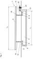
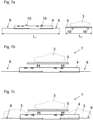
- a first exemplary embodiment of a support device 1 according to the invention is shown in a schematic side view, in which the length L 2 over which the second support 5 extends is greater than the length L 1 over which the first support 4 extends.
- the length L 2 is selected in such a way that the second support 5 projects beyond the pocket 13 of the pocket wagon 2 .
- the first and second support 4, 5 are designed passable.
- the second support 5 is supported on the first support 4 via coupling points 15 , 16 .
- the length of the first support 4 is within the pocket 13 of the pocket wagon 2.
- the first and the second support 4, 5 have a fixed orientation (here at least essentially horizontal).
- the position of the first support 4 is secured in particular against longitudinal displacements via a section 23 which projects beyond the pocket 13 with an ISO pin 24 of the pocket wagon 2 which is arranged outside the pocket 13 (this measure is only shown for this exemplary embodiment, but can be provided for all exemplary embodiments being).
- the second support 5 can be loaded with more vehicles 3 (or a longer vehicle) than the first support 4.
- the first support 4 can be loaded with two vehicles 3 and the second support 5 with three vehicles 3.
- the first support 4 has two tiltable sections 8, 9, which can be moved between a receiving position for one vehicle 3 each, in which the vehicle 3 is aligned substantially horizontally, and a loading position for the vehicle 3, in which the vehicle 3 is tilted are (see for example Fig. 5f ).
- the inclinable partial areas 8, 9 are freely pivotably mounted on a frame or longitudinal beams 7 of the first support 4 - possibly except for the action of a damping device (cf. Figure 5a ).
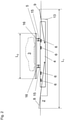
- the first support 4 can in principle be loaded with more vehicles 3 than the second support 5.
- the first support 4 can be loaded with two vehicles 3 and the second support 5 with one vehicle 3.
- the second support 5 extends longitudinally only over part of the first support 4 and is designed in the form of a plateau with a fixed (here at least essentially horizontal) orientation, which is supported on the first support 4 via coupling points 15, 16. At least one of the inclinable sections 8, 9 of the first support 4 can extend under the second support 5 in the inclined state.
- the inclinable sections 8, 9 of the first support 4 extend in the illustrated state, lifted onto a pocket wagon 2, beyond the pocket 13 of the pocket wagon 2.
- the longitudinal extension of the second support 5 is inside the pocket 13 of the pocket wagon 2.
- the pivot axes of the inclination of the inclinable partial areas 8, 9 are here inside the pocket 13 of the pocket wagon 2, but could also alternatively be outside and above the pocket 13 (cf. the tiltable section 9 in Fig. 5f and 5g ).
- the first support 4 has two inclinable sections 8, 9, each of which moves between a pick-up position for one vehicle 3, in which the vehicle 3 is aligned essentially horizontally, and a loading position for the vehicle 3, in which the Vehicle 3 is inclined, are movable.
- the inclinable partial areas 8, 9 are freely pivotably mounted on a frame or longitudinal beams 7 of the first support 4--possibly up to the action of a damping device.
- the second support 5 has a section 10 with a predetermined inclination before loading, so that more height is available below section 10 (cf. Figure 6b ).
- the inclinable sections 8, 9 of the first support 4 extend in the illustrated state, lifted onto a pocket wagon 2, beyond the pocket 13 of the pocket wagon 2.
- the pivot axes of the inclination of the inclinable sections 8, 9 are located within the pocket 13 of the pocket wagon 2, but could also alternatively be located outside and above the pocket 13 (cf. the inclinable section 9 in Fig. 5f and 5g ).
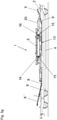
- the length L 2 over which the second support 5 extends is greater than the length L 1 over which the first support 4 extends and the first support 4 has a region with a fixed (here at least substantially horizontal orientation) and the second support 5 has three sections 10, 11, 12 with an inclination that can be predetermined before loading.
- the first support 4 is located in its longitudinal extent within the pocket 13 of the pocket wagon 2.
- the second support 5 can in principle be loaded with more vehicles 3 than the first support 4. For example, the first support 4 with two vehicles 3 and the second support 5 with three vehicles 3 loaded.
- the two outer inclined partial areas 10, 12 of the second support 5 extend in the illustrated state, raised onto a pocket wagon 2, beyond the pocket 13 of the pocket wagon 2, the middle inclined partial area 11 is located above the pocket 13 of the pocket wagon 2.
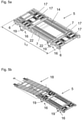
- Fig. 5a-d show second supports 5 of a further exemplary embodiment of a carrying device 1 according to the invention.
- the second support 5 has two longitudinal beams 7, between which a roadway 14 for vehicles 3 is arranged in the form of a combination (in the longitudinal extension) of beams and struts.
- the longitudinal beams 7 are connected to one another via cross braces 17 .
- Two coupling points 16 are arranged on both sides of the second support 5, via which the second support 5 can be releasably connected to a first support 4 (via coupling points 15).
- Receiving pockets 6 are provided for a lifting device, so that the second support 5 can be lifted by a lifting device.
- a ramp 18 can be placed on the second support 5, which has contact surfaces on its underside (in this exemplary embodiment formed by the support feet 19 of the coupling point 16) for standing up on a terminal corridor, in order to prevent a vehicle 3 from driving up or down facilitate. This of course applies to all exemplary embodiments.
- second supports 5 can be stacked on top of one another via the coupling points 16 for empty transport (cf. Figures 5c and 5d ) and stored in this state on a first support 4 or directly on a pocket wagon 2.
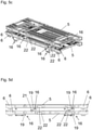
- Figure 5e shows a first support 4 of an embodiment of a support device 1 according to the invention
- the first support 4 has two longitudinal beams 7, between which a roadway 14 for vehicles 3 is arranged in the form of a combination (in the longitudinal extension) of beams and struts.
- the longitudinal beams 7 are connected to one another via cross braces 17 .
- On both sides of the first support 4 two coupling points 15 are arranged, via which the first Support 4 is releasably connected to a second support 5.
- Receiving pockets 6 are provided for a lifting device, so that the first support 4 can be lifted.
- the roadway 14 is partially formed on two inclinable partial areas 8, 9, which between a receiving position for a vehicle 3, in which the vehicle 3 is aligned substantially horizontally, and a loading position for the vehicle 3, in which the vehicle 3 is inclined, are movable (the recording position is shown in each case).
- the inclinable partial areas 8, 9 are mounted so that they can pivot freely, possibly except for the action of a damping device. Between the two inclinable sub-areas 8, 9 another passable sub-area with a fixed (here essentially horizontal) orientation is arranged.
- One inclinable section 9 is arranged on the first support 4 via pivoted arms 20 .
- the arms 20 are arranged on pivot bearings outside the passable width of the roadway 14 .
- the pivot bearings are located partly within a profiled section of the longitudinal members 7 and partly on the outside of the longitudinal members 7.
- a length of the arms 20 is selected such that the further sub-area arranged between the inclinable sub-areas 9, 10 is lengthened by the inclinable sub-area 9 in a drivable manner in the illustrated first pivoted position of the arms 20.
- the inclinable section 9 can be lengthened by an extension 9' in the direction of the further section.
- the inclinable partial area 8 it is designed to be variable in length, as shown.
- the ability to change the length is realized by two nested, telescopically extendable extension parts 8', 8''.
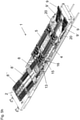
- Fig. 5f shows a carrying device 1 of the embodiment of FIG 2 with vehicles 3 loaded on a pocket wagon 2 below Use of the first and second supports 4, 5 after Figure 5a and 5e .
- the second support 5 only extends over part of the first support 4 in the longitudinal direction and is designed in the form of a plateau with a fixed (here at least essentially horizontal) orientation, which extends over the coupling points 15, 16 on the first Support 4 supports.
- the inclinable sections 8, 9 of the first support 4 extend in the illustrated state, lifted onto a pocket wagon 2, beyond the pocket 13 of the pocket wagon 2.
- the second support 5 is located inside the pocket 13 of the pocket wagon 2 in plan view.
- the pivot axes of the inclination of the inclinable sections 8, 9 are located inside the pocket 13 of the pocket wagon 2.
- the vehicles 3 arranged on the first support 4 protrude below the one on the second support 5 arranged vehicle 3 inside.
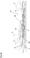
- Fig. 5g shows the carrying device 1 Fig. 5f without vehicles 3 on a pocket wagon 2.
- Figure 5h shows a perspective view of Fig. 5g .
- Fig. 5i-k show an embodiment of a coupling point 16 of the second support 5, in which the coupling point 16 has a support foot 19 which is arranged on a leg 25.
- the support foot 19 has a receiving opening 26 which can serve to receive a projection of a coupling point 15 of the first support 4 .
- the receiving opening 26 can also be used for coupling to a further second support 5 .
- the coupling point 16 has a strut 27, which is used in the strutted state (cf. Fig. 5j ) Introduce dynamic forces into the second support 5 when the pocket wagon 2 is in motion. For example, torsional forces acting on the leg 25 can be reduced.
- the leg 25, and hence the support foot 19, can be placed in various orientations on the second support 5 (e.g. by being inserted into a socket in the desired orientation).
- the orientation shown is suitable for the coupling point 16 for connecting the second support 5 to a coupling point 15 of the first support 4.
- the coupling point 16 is suitable for connecting the second support 5 to a further second support 5, for example via a connection as shown in FIG Fig. 5j illustrated twist-lock connection 21 (see also Figure 5d ).
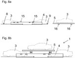
- Figure 6a shows a second support 5 of an embodiment of a support device according to the invention 1.
- the second support 5 has two sections 10, 11 with an inclination that can be selected before loading and is fixed in the loaded state.
- the inclination of the partial area 10 is predetermined, for example, by selecting the height of the supports 28, which are arranged on the second support 5 (in Figure 6a one support 28 is covered by the visible support 28).
- the second support 5 can be designed as shown in FIGS Figures 5a - 5d shown. in the in Figure 6a
- the state shown can serve the sub-area 11 in conjunction with the sub-area 9 of the first support 4 as a ramp for a vehicle 3 to reach the sub-area 10. Thereafter, the portion 11 can be removed.
- the partial area 11 can be used again for discharging.
- Figure 6b shows a carrying device 1 with vehicles 3 in the loaded state on a pocket wagon 2 using the first and second supports 4, 5 Figure 5e and 6a , wherein the portion 11 of the second support 5 has been removed.
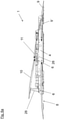
- FIG. 7a-c is a first embodiment of a method for loading a pocket wagon 2 using first and second supports 4, 5, from which a support device 1 according to the invention is formed, shown.
- the length L 1 over which the first support 4 extends (the inclinable supports 8, 9 of the first support 4 are in the receiving position) is greater than the length L 2 over which the second support 5 extends.
- the exemplary embodiment shown uses an exemplary embodiment of a carrying device 1 as an example 2 .
- FIG 7c the state is shown which results when two vehicles 3 are (have) driven onto the first support 4 .
- the loaded carrying device 1 can now be lifted onto a pocket wagon 2 (not shown) by means of the receiving points of the first support 4 by a lifting device (not shown).
Landscapes
- Engineering & Computer Science (AREA)
- Mechanical Engineering (AREA)
- Transportation (AREA)
- Health & Medical Sciences (AREA)
- Public Health (AREA)
- Handcart (AREA)
Priority Applications (4)
| Application Number | Priority Date | Filing Date | Title |
|---|---|---|---|
| PL18187294T PL3604072T3 (pl) | 2018-08-03 | 2018-08-03 | Podnoszone urządzenie nośne |
| EP18187294.6A EP3604072B1 (de) | 2018-08-03 | 2018-08-03 | Hebbare tragvorrichtung |
| US16/530,105 US11008023B2 (en) | 2018-08-03 | 2019-08-02 | Liftable carrying apparatus |
| CN201910709354.6A CN110789427B (zh) | 2018-08-03 | 2019-08-02 | 小型货车和用于对小型货车进行装载或卸载的方法 |
Applications Claiming Priority (1)
| Application Number | Priority Date | Filing Date | Title |
|---|---|---|---|
| EP18187294.6A EP3604072B1 (de) | 2018-08-03 | 2018-08-03 | Hebbare tragvorrichtung |
Publications (2)
| Publication Number | Publication Date |
|---|---|
| EP3604072A1 EP3604072A1 (de) | 2020-02-05 |
| EP3604072B1 true EP3604072B1 (de) | 2022-02-09 |
Family
ID=63207533
Family Applications (1)
| Application Number | Title | Priority Date | Filing Date |
|---|---|---|---|
| EP18187294.6A Active EP3604072B1 (de) | 2018-08-03 | 2018-08-03 | Hebbare tragvorrichtung |
Country Status (4)
| Country | Link |
|---|---|
| US (1) | US11008023B2 (pl) |
| EP (1) | EP3604072B1 (pl) |
| CN (1) | CN110789427B (pl) |
| PL (1) | PL3604072T3 (pl) |
Families Citing this family (2)
| Publication number | Priority date | Publication date | Assignee | Title |
|---|---|---|---|---|
| DE102018204089A1 (de) * | 2018-03-16 | 2019-09-19 | Franz Blum | Güterwagen zum Transport von Ladegut und Wanne für einen solchen Güterwagen |
| CN115743194B (zh) * | 2022-09-30 | 2025-06-17 | 中车齐齐哈尔车辆有限公司 | 一种凹底平车结构 |
Family Cites Families (23)
| Publication number | Priority date | Publication date | Assignee | Title |
|---|---|---|---|---|
| US3646609A (en) * | 1969-06-06 | 1972-02-29 | Sea Land Service | Container for handling freight |
| NL7210267A (pl) * | 1971-07-30 | 1973-02-01 | ||
| US4124119A (en) * | 1977-08-02 | 1978-11-07 | Transequip Inc. | Automobile carrier for use on air cargo pallets |
| WO1981001997A1 (fr) * | 1980-01-13 | 1981-07-23 | Y Yonahara | Appareil de logement de voitures pour transport par mer |
| WO1987006895A1 (fr) * | 1986-05-07 | 1987-11-19 | Mitsubishi Jidosha Kogyo Kabushiki Kaisha | Dispositif du type a deux etages pour charger des automobiles sur un conteneur, et methode de fonctionnement |
| AT388720B (de) | 1987-06-23 | 1989-08-25 | Austria Metall | Stapelbares lagergestell |
| US4986705A (en) * | 1987-11-25 | 1991-01-22 | Eis Corporation | Stackable freight container for holding stacked chassis |
| FR2650547B1 (fr) * | 1989-08-01 | 1991-10-11 | Lohr Ind | Pont superieur mobile pour wagon polyvalent porte-vehicules |
| US5213458A (en) | 1990-07-27 | 1993-05-25 | Sea-Land Corporation, Inc. | Method and apparatus for containerized shipment of automobiles |
| JPH06503535A (ja) * | 1990-12-10 | 1994-04-21 | ランプ インターナショナル イースト コースト ユー.エス.エイ.,インコーポレイテッド | 貨物と自動車を収納する可動プラットホーム |
| US5255806A (en) * | 1991-05-03 | 1993-10-26 | Stoughton Composites, Inc. | Reinforced plastic composite intermodal vehicle hauler |
| US5344266A (en) * | 1993-04-16 | 1994-09-06 | Kolb Peter W | Fully adjustable storage device for loading and transporting vehicles in containers |
| US5890855A (en) * | 1994-04-15 | 1999-04-06 | Claps; William R. | Method and apparatus for transporting cars |
| US5863173A (en) * | 1998-01-27 | 1999-01-26 | Arman Industries Ltd. | Vehicular deck attachment and assembly |
| US6655300B1 (en) * | 1999-05-12 | 2003-12-02 | Martin Clive-Smith | Adjustable post for container |
| CN2406886Y (zh) * | 2000-02-22 | 2000-11-22 | 江苏双良停车设备有限公司 | 运输小型车辆的双层运输架装置 |
| FI20000618A0 (fi) * | 2000-03-16 | 2000-03-16 | Peramar Oy | Menetelmä ja laitteisto autojen kuljettamiseksi |
| US20070189872A1 (en) * | 2003-10-10 | 2007-08-16 | Mamoru Omuta | Freight rack |
| EP2441701B1 (de) * | 2010-10-15 | 2014-07-02 | Deutsche Post AG | Transportvorrichtung und Transportmittel damit |
| WO2014017917A2 (en) | 2012-07-27 | 2014-01-30 | Van Uden Finance B.V. | Passenger car transport device and method for packaging cars for transport |
| TR201902634T3 (tr) | 2015-03-11 | 2019-06-21 | Blum Franz | Yükseltilebilir Taşıma Aleti. |
| FR3046577B1 (fr) * | 2016-01-07 | 2019-07-05 | Lohr Industrie | Palette repliable a deux niveaux de chargement |
| EP3604075B1 (de) * | 2018-08-03 | 2021-02-24 | Kässbohrer Transport Technik GmbH | Hebbare tragvorrichtung |
-
2018
- 2018-08-03 EP EP18187294.6A patent/EP3604072B1/de active Active
- 2018-08-03 PL PL18187294T patent/PL3604072T3/pl unknown
-
2019
- 2019-08-02 CN CN201910709354.6A patent/CN110789427B/zh active Active
- 2019-08-02 US US16/530,105 patent/US11008023B2/en active Active
Also Published As
| Publication number | Publication date |
|---|---|
| US20200039735A1 (en) | 2020-02-06 |
| CN110789427B (zh) | 2022-10-11 |
| US11008023B2 (en) | 2021-05-18 |
| EP3604072A1 (de) | 2020-02-05 |
| CN110789427A (zh) | 2020-02-14 |
| PL3604072T3 (pl) | 2022-05-23 |
Similar Documents
| Publication | Publication Date | Title |
|---|---|---|
| EP2079607B1 (de) | Flurgebundenes transportfahrzeug, insbesondere für den transport von containern | |
| DE69517176T2 (de) | Verfahren und vorrichtung zum übertragen von ladeeinheiten zwischen zwei trägern | |
| EP3268257B1 (de) | Hebbare tragvorrichtung | |
| DE2731386C2 (pl) | ||
| EP3604075B1 (de) | Hebbare tragvorrichtung | |
| DE202018106492U1 (de) | Fahrzeug zum Transportieren eines langen Transportguts | |
| EP3699058A1 (de) | Anordnung aus schienenfahrzeug und tragvorrichtung | |
| EP3620327B1 (de) | Hakenliftfahrzeug sowie container für ein hakenliftfahrzeug | |
| EP1329357A2 (de) | Kipperfahrzeug | |
| EP3604072B1 (de) | Hebbare tragvorrichtung | |
| EP0285698A1 (de) | Nutzfahrzeug mit Wechselaufbau | |
| EP1907310B1 (de) | Anhänger für ein kraftfahrzeug | |
| DE19512246C2 (de) | Selbstfahrendes und auf ein Transportfahrzeug selbstauf- und selbstabladbares Verladesystem für Container oder Wechselbrücken | |
| DE102017111609B3 (de) | Nutzfahrzeug mit beweglicher Ladeplattform | |
| EP3385119A1 (de) | Mehrfunktions-transportfahrzeug mit klappbarem transportgestell | |
| DE2632492C3 (de) | Transportfahrzeug zum Transport von Großbehältern | |
| DE2641262A1 (de) | Seitenlader fuer container | |
| EP3785988A1 (de) | Fahrzeugtransporter | |
| WO1986002326A1 (fr) | Remorque a essieu unique | |
| WO1994018047A1 (de) | Liftrahmen | |
| DE9420484U1 (de) | Nutzfahrzeug zum Transport unterschiedlicher Aufbauten | |
| DE19950553C2 (de) | LKW-Hubvorrichtung für unterfahrbare Wechselbehälter | |
| WO2006045609A1 (de) | Mobilkran | |
| EP1688300B1 (de) | Vorrichtung zum Be- und Entladen einer Ladefläche | |
| DE102019120134B3 (de) | Fahrzeugkran und Fahrzeugkransystem sowie Verfahren zum Aufrüsten und Abrüsten eines Fahrzeugkrans mit einer Abspannvorrichtung |
Legal Events
| Date | Code | Title | Description |
|---|---|---|---|
| PUAI | Public reference made under article 153(3) epc to a published international application that has entered the european phase |
Free format text: ORIGINAL CODE: 0009012 |
|
| STAA | Information on the status of an ep patent application or granted ep patent |
Free format text: STATUS: THE APPLICATION HAS BEEN PUBLISHED |
|
| AK | Designated contracting states |
Kind code of ref document: A1 Designated state(s): AL AT BE BG CH CY CZ DE DK EE ES FI FR GB GR HR HU IE IS IT LI LT LU LV MC MK MT NL NO PL PT RO RS SE SI SK SM TR |
|
| AX | Request for extension of the european patent |
Extension state: BA ME |
|
| STAA | Information on the status of an ep patent application or granted ep patent |
Free format text: STATUS: REQUEST FOR EXAMINATION WAS MADE |
|
| 17P | Request for examination filed |
Effective date: 20200805 |
|
| RBV | Designated contracting states (corrected) |
Designated state(s): AL AT BE BG CH CY CZ DE DK EE ES FI FR GB GR HR HU IE IS IT LI LT LU LV MC MK MT NL NO PL PT RO RS SE SI SK SM TR |
|
| RIC1 | Information provided on ipc code assigned before grant |
Ipc: B61D 3/18 20060101AFI20210520BHEP |
|
| GRAP | Despatch of communication of intention to grant a patent |
Free format text: ORIGINAL CODE: EPIDOSNIGR1 |
|
| STAA | Information on the status of an ep patent application or granted ep patent |
Free format text: STATUS: GRANT OF PATENT IS INTENDED |
|
| INTG | Intention to grant announced |
Effective date: 20210625 |
|
| GRAJ | Information related to disapproval of communication of intention to grant by the applicant or resumption of examination proceedings by the epo deleted |
Free format text: ORIGINAL CODE: EPIDOSDIGR1 |
|
| STAA | Information on the status of an ep patent application or granted ep patent |
Free format text: STATUS: REQUEST FOR EXAMINATION WAS MADE |
|
| GRAS | Grant fee paid |
Free format text: ORIGINAL CODE: EPIDOSNIGR3 |
|
| STAA | Information on the status of an ep patent application or granted ep patent |
Free format text: STATUS: GRANT OF PATENT IS INTENDED |
|
| GRAP | Despatch of communication of intention to grant a patent |
Free format text: ORIGINAL CODE: EPIDOSNIGR1 |
|
| INTC | Intention to grant announced (deleted) | ||
| INTG | Intention to grant announced |
Effective date: 20211112 |
|
| GRAA | (expected) grant |
Free format text: ORIGINAL CODE: 0009210 |
|
| STAA | Information on the status of an ep patent application or granted ep patent |
Free format text: STATUS: THE PATENT HAS BEEN GRANTED |
|
| AK | Designated contracting states |
Kind code of ref document: B1 Designated state(s): AL AT BE BG CH CY CZ DE DK EE ES FI FR GB GR HR HU IE IS IT LI LT LU LV MC MK MT NL NO PL PT RO RS SE SI SK SM TR |
|
| REG | Reference to a national code |
Ref country code: GB Ref legal event code: FG4D Free format text: NOT ENGLISH |
|
| REG | Reference to a national code |
Ref country code: CH Ref legal event code: EP Ref country code: AT Ref legal event code: REF Ref document number: 1467326 Country of ref document: AT Kind code of ref document: T Effective date: 20220215 |
|
| REG | Reference to a national code |
Ref country code: IE Ref legal event code: FG4D Free format text: LANGUAGE OF EP DOCUMENT: GERMAN |
|
| REG | Reference to a national code |
Ref country code: DE Ref legal event code: R096 Ref document number: 502018008719 Country of ref document: DE |
|
| REG | Reference to a national code |
Ref country code: LT Ref legal event code: MG9D |
|
| REG | Reference to a national code |
Ref country code: NL Ref legal event code: MP Effective date: 20220209 |
|
| PG25 | Lapsed in a contracting state [announced via postgrant information from national office to epo] |
Ref country code: SE Free format text: LAPSE BECAUSE OF FAILURE TO SUBMIT A TRANSLATION OF THE DESCRIPTION OR TO PAY THE FEE WITHIN THE PRESCRIBED TIME-LIMIT Effective date: 20220209 Ref country code: RS Free format text: LAPSE BECAUSE OF FAILURE TO SUBMIT A TRANSLATION OF THE DESCRIPTION OR TO PAY THE FEE WITHIN THE PRESCRIBED TIME-LIMIT Effective date: 20220209 Ref country code: PT Free format text: LAPSE BECAUSE OF FAILURE TO SUBMIT A TRANSLATION OF THE DESCRIPTION OR TO PAY THE FEE WITHIN THE PRESCRIBED TIME-LIMIT Effective date: 20220609 Ref country code: NO Free format text: LAPSE BECAUSE OF FAILURE TO SUBMIT A TRANSLATION OF THE DESCRIPTION OR TO PAY THE FEE WITHIN THE PRESCRIBED TIME-LIMIT Effective date: 20220509 Ref country code: NL Free format text: LAPSE BECAUSE OF FAILURE TO SUBMIT A TRANSLATION OF THE DESCRIPTION OR TO PAY THE FEE WITHIN THE PRESCRIBED TIME-LIMIT Effective date: 20220209 Ref country code: LT Free format text: LAPSE BECAUSE OF FAILURE TO SUBMIT A TRANSLATION OF THE DESCRIPTION OR TO PAY THE FEE WITHIN THE PRESCRIBED TIME-LIMIT Effective date: 20220209 Ref country code: HR Free format text: LAPSE BECAUSE OF FAILURE TO SUBMIT A TRANSLATION OF THE DESCRIPTION OR TO PAY THE FEE WITHIN THE PRESCRIBED TIME-LIMIT Effective date: 20220209 Ref country code: ES Free format text: LAPSE BECAUSE OF FAILURE TO SUBMIT A TRANSLATION OF THE DESCRIPTION OR TO PAY THE FEE WITHIN THE PRESCRIBED TIME-LIMIT Effective date: 20220209 Ref country code: BG Free format text: LAPSE BECAUSE OF FAILURE TO SUBMIT A TRANSLATION OF THE DESCRIPTION OR TO PAY THE FEE WITHIN THE PRESCRIBED TIME-LIMIT Effective date: 20220509 |
|
| PG25 | Lapsed in a contracting state [announced via postgrant information from national office to epo] |
Ref country code: LV Free format text: LAPSE BECAUSE OF FAILURE TO SUBMIT A TRANSLATION OF THE DESCRIPTION OR TO PAY THE FEE WITHIN THE PRESCRIBED TIME-LIMIT Effective date: 20220209 Ref country code: GR Free format text: LAPSE BECAUSE OF FAILURE TO SUBMIT A TRANSLATION OF THE DESCRIPTION OR TO PAY THE FEE WITHIN THE PRESCRIBED TIME-LIMIT Effective date: 20220510 Ref country code: FI Free format text: LAPSE BECAUSE OF FAILURE TO SUBMIT A TRANSLATION OF THE DESCRIPTION OR TO PAY THE FEE WITHIN THE PRESCRIBED TIME-LIMIT Effective date: 20220209 |
|
| PG25 | Lapsed in a contracting state [announced via postgrant information from national office to epo] |
Ref country code: IS Free format text: LAPSE BECAUSE OF FAILURE TO SUBMIT A TRANSLATION OF THE DESCRIPTION OR TO PAY THE FEE WITHIN THE PRESCRIBED TIME-LIMIT Effective date: 20220609 |
|
| PG25 | Lapsed in a contracting state [announced via postgrant information from national office to epo] |
Ref country code: SM Free format text: LAPSE BECAUSE OF FAILURE TO SUBMIT A TRANSLATION OF THE DESCRIPTION OR TO PAY THE FEE WITHIN THE PRESCRIBED TIME-LIMIT Effective date: 20220209 Ref country code: SK Free format text: LAPSE BECAUSE OF FAILURE TO SUBMIT A TRANSLATION OF THE DESCRIPTION OR TO PAY THE FEE WITHIN THE PRESCRIBED TIME-LIMIT Effective date: 20220209 Ref country code: RO Free format text: LAPSE BECAUSE OF FAILURE TO SUBMIT A TRANSLATION OF THE DESCRIPTION OR TO PAY THE FEE WITHIN THE PRESCRIBED TIME-LIMIT Effective date: 20220209 Ref country code: EE Free format text: LAPSE BECAUSE OF FAILURE TO SUBMIT A TRANSLATION OF THE DESCRIPTION OR TO PAY THE FEE WITHIN THE PRESCRIBED TIME-LIMIT Effective date: 20220209 Ref country code: DK Free format text: LAPSE BECAUSE OF FAILURE TO SUBMIT A TRANSLATION OF THE DESCRIPTION OR TO PAY THE FEE WITHIN THE PRESCRIBED TIME-LIMIT Effective date: 20220209 Ref country code: CZ Free format text: LAPSE BECAUSE OF FAILURE TO SUBMIT A TRANSLATION OF THE DESCRIPTION OR TO PAY THE FEE WITHIN THE PRESCRIBED TIME-LIMIT Effective date: 20220209 |
|
| REG | Reference to a national code |
Ref country code: DE Ref legal event code: R097 Ref document number: 502018008719 Country of ref document: DE |
|
| PG25 | Lapsed in a contracting state [announced via postgrant information from national office to epo] |
Ref country code: AL Free format text: LAPSE BECAUSE OF FAILURE TO SUBMIT A TRANSLATION OF THE DESCRIPTION OR TO PAY THE FEE WITHIN THE PRESCRIBED TIME-LIMIT Effective date: 20220209 |
|
| PLBE | No opposition filed within time limit |
Free format text: ORIGINAL CODE: 0009261 |
|
| STAA | Information on the status of an ep patent application or granted ep patent |
Free format text: STATUS: NO OPPOSITION FILED WITHIN TIME LIMIT |
|
| 26N | No opposition filed |
Effective date: 20221110 |
|
| PG25 | Lapsed in a contracting state [announced via postgrant information from national office to epo] |
Ref country code: SI Free format text: LAPSE BECAUSE OF FAILURE TO SUBMIT A TRANSLATION OF THE DESCRIPTION OR TO PAY THE FEE WITHIN THE PRESCRIBED TIME-LIMIT Effective date: 20220209 |
|
| PG25 | Lapsed in a contracting state [announced via postgrant information from national office to epo] |
Ref country code: MC Free format text: LAPSE BECAUSE OF FAILURE TO SUBMIT A TRANSLATION OF THE DESCRIPTION OR TO PAY THE FEE WITHIN THE PRESCRIBED TIME-LIMIT Effective date: 20220209 |
|
| REG | Reference to a national code |
Ref country code: CH Ref legal event code: PL |
|
| GBPC | Gb: european patent ceased through non-payment of renewal fee |
Effective date: 20220803 |
|
| PG25 | Lapsed in a contracting state [announced via postgrant information from national office to epo] |
Ref country code: LU Free format text: LAPSE BECAUSE OF NON-PAYMENT OF DUE FEES Effective date: 20220803 Ref country code: LI Free format text: LAPSE BECAUSE OF NON-PAYMENT OF DUE FEES Effective date: 20220831 Ref country code: CH Free format text: LAPSE BECAUSE OF NON-PAYMENT OF DUE FEES Effective date: 20220831 |
|
| REG | Reference to a national code |
Ref country code: BE Ref legal event code: MM Effective date: 20220831 |
|
| PG25 | Lapsed in a contracting state [announced via postgrant information from national office to epo] |
Ref country code: IE Free format text: LAPSE BECAUSE OF NON-PAYMENT OF DUE FEES Effective date: 20220803 |
|
| PG25 | Lapsed in a contracting state [announced via postgrant information from national office to epo] |
Ref country code: BE Free format text: LAPSE BECAUSE OF NON-PAYMENT OF DUE FEES Effective date: 20220831 |
|
| PG25 | Lapsed in a contracting state [announced via postgrant information from national office to epo] |
Ref country code: GB Free format text: LAPSE BECAUSE OF NON-PAYMENT OF DUE FEES Effective date: 20220803 |
|
| PG25 | Lapsed in a contracting state [announced via postgrant information from national office to epo] |
Ref country code: HU Free format text: LAPSE BECAUSE OF FAILURE TO SUBMIT A TRANSLATION OF THE DESCRIPTION OR TO PAY THE FEE WITHIN THE PRESCRIBED TIME-LIMIT; INVALID AB INITIO Effective date: 20180803 |
|
| PG25 | Lapsed in a contracting state [announced via postgrant information from national office to epo] |
Ref country code: MK Free format text: LAPSE BECAUSE OF FAILURE TO SUBMIT A TRANSLATION OF THE DESCRIPTION OR TO PAY THE FEE WITHIN THE PRESCRIBED TIME-LIMIT Effective date: 20220209 Ref country code: CY Free format text: LAPSE BECAUSE OF FAILURE TO SUBMIT A TRANSLATION OF THE DESCRIPTION OR TO PAY THE FEE WITHIN THE PRESCRIBED TIME-LIMIT Effective date: 20220209 |
|
| PG25 | Lapsed in a contracting state [announced via postgrant information from national office to epo] |
Ref country code: MT Free format text: LAPSE BECAUSE OF FAILURE TO SUBMIT A TRANSLATION OF THE DESCRIPTION OR TO PAY THE FEE WITHIN THE PRESCRIBED TIME-LIMIT Effective date: 20220209 |
|
| PGFP | Annual fee paid to national office [announced via postgrant information from national office to epo] |
Ref country code: DE Payment date: 20250829 Year of fee payment: 8 |
|
| PGFP | Annual fee paid to national office [announced via postgrant information from national office to epo] |
Ref country code: PL Payment date: 20250708 Year of fee payment: 8 Ref country code: IT Payment date: 20250806 Year of fee payment: 8 |
|
| PGFP | Annual fee paid to national office [announced via postgrant information from national office to epo] |
Ref country code: FR Payment date: 20250724 Year of fee payment: 8 Ref country code: AT Payment date: 20250827 Year of fee payment: 8 |